

Page 1

Quadrus Verifier
User's Manual
P/N 83-006702 Rev C
Page 2

Copyright and Disclaimer
Copyright © 2007
by Microscan Systems, Inc.,
1201 S.W. 7th Street, Renton, Washington, U.S.A. 98057
(425) 226-5700 FAX: (425) 226-8682
ISO 9001:2000 Certification No. 06-1080
Issued by TüV USA
All rights reserved. The information contain ed herein is proprietary and is provided solely for the purpose
of allowing customers to operate and/or service Microscan manufactured equipment and is not to be
released, reproduced, or used for any other purpose without written permission of Microscan.
Throughout this manual, trademarked names might be used. Rather than put a tra demark (™) s y mbol in
every occurrence of a trademarked name, we state herein that we are using the names only in an ed itorial
fashion, and to the benefit of the trademark owner, with no intention of infringement.
Disclaimer
The information and specifications described in this manual are subject to change without notice.
Latest Manual Version
For the latest version of this manual, see the Download page on our web site at www.microscan.com.
For technical support email helpdesk@microscan.com.
Microscan Systems, Inc.
1201 S.W. 7th Street
Renton, WA 98057
U.S.A.
Tel: 425 226 5700
Fax: 425 226 8250
helpdesk@microscan.com
Microscan Europe
Tel: 31 172 423360
Fax: 31 172 423366
Microscan Asia Pacific R.O.
Tel: 65 6846 1214
Fax: 65 6846 4641
ii Quadrus Verifier User’s Manual
Page 3

Introduction
Microscan Limited Warranty Statement and Exclusions
What Is Covered?
Microscan Systems Inc. warrants to the original purchaser that products manufactured by it will be free
from defects in material and workmanship under normal use a nd se rvice for a perio d of one year f rom th e
date of shipment. This warranty is specifically limited to, at Mic roscan’s sole option, repair or replacement
with a functionally equivalent unit and return without charg e for service or return freight.
What Is Excluded?
This limited warranty specifically excludes the following: (1) Any products or parts that have been subject
to misuse, neglect, accident, unauthorized rep air, improper installation, or abnormal condit ions or operations; (2) Any products or parts that have been transferred by the original purchaser; (3) Customer misadjustment of settings contrary to the procedure d escribed i n the Microscan Syst ems Inc. owners manual;
(4) Upgrading software versions at customer request unl ess required to meet specifications in eff ect at the
time of purchase; (5) Units returned and found to have no failure will be excluded; (6) Claims for damage
in transit are to be directed to the freight c arrier upon receipt . Any use of t he product is at purchaser’s own
risk. This limited warranty is the only warranty provided by Microscan Systems Inc. regarding the product .
Except for the limited warranty above, the pro duct is pro vided “as is.” To the maximum extent permi tted by
law, this express warranty excludes all other warranties, express or implied, including but not limited to,
implied warranties of merchantability and. Technical support questions may be directed to: helpdesk@microscan.com Register your product with Microscan: www.microscan.com/register fitness for a
particular purpose. Microscan Systems Inc. does not warrant that the functions contained in the product
will meet any requirements or needs purchaser may have, or that the product will operate error free, or in
an uninterrupted fashion, or that any defects or errors in the product will be corrected, or that the product
is compatible with any particular machinery.
Limitation of Liability
In no event shall Microscan Systems Inc. be liable to you or any third party for any special, incidental, or
consequential damages (including, without limit ation, i ndirect, special, punitive, or exemplary da mages for
loss of business, loss of profits, business in terruption, or loss of business informat ion), whether in contract,
tort, or otherwise, even if Microscan Systems Inc. has been advised of the possibility of such damages.
Microscan Systems Inc.’s aggregate liabil ity with respect to it s obligations under t his warranty or otherwise
with respect to the product and documentation or otherwise shall not exceed the amount paid by you for
the product and documentation. Some jurisdictions do not allow the exclusion or limitation of incidental or
consequential damages or limitations on an impli ed warranty, so the above limitation or exclusion may not
apply to you. This warranty gives you specific legal rights, and you may also have other rights which may
vary from state to state.
Tel: 425.226.5700 | Fax: 425.226.8250 | helpdesk@microscan.com
Quadrus Verifier User’s Manual iii
Page 4

Table of Contents
Table of Contents
Chapter 1 Quick Start
Step 1 Check Required Hardware........................................................... 1-2
Step 2 Connect the System..................................................................... 1-3
Step 3 Install ESP ...................................................................................1-4
Step 4 Select Model................................................................................1-5
Step 5 Select Communications Protocol................................................. 1-6
Step 6 Position Verifier and Symbol........................................................1-7
Step 7 Locate Symbol............................................................................ 1-8
Step 8 Calibrate Reflectance................................................................... 1-9
Step 9 Set Verification Parameters ..................................................... 1-10
Step 10 Verify Symbol ........................................................... ... ........... 1-11
Step 11 Generate and Save Verification Report ................................. 1-14
Chapter 2 Using ESP
Verification...............................................................................................2-2
Application Mode..................................................................................... 2-3
Menu Toolbar ..........................................................................................2-4
View......................................................... ............................................. 2-11
Navigating in ESP .................................................................................2-12
Send/Receive Options...........................................................................2-13
Chapter 3 Verification
Verification Serial Commands................................................................. 3-2
Verification Operational Commands........................................................ 3-2
Overview of Verification...........................................................................3-3
ISO/IEC 15415 Evaluation Parameters...................................................3-5
AS9132 Evaluation Parameters ..............................................................3-7
AIM DPM Evaluation Parameters...................................................... ... .3-10
General Verification Serial Output.........................................................3-12
General Verification Output by ESP.............................. ... ..................... 3-17
ISO/IEC 15415 Verification Setup.........................................................3-19
ISO/IEC 15415 Verification Setup by ESP............................................3-21
ISO/IEC 15415 Serial Output ................................................................ 3-23
ISO/IEC 15415 Output by ESP .............................................................3-33
AIM DPM Verification Setup..................................................................3-40
AIM DPM Verification Setup by ESP .....................................................3-42
ISO/IEC 15415 Verification by Serial Command................................... 3-44
AS9132/JES 131 Marking Method........................................................ 3-49
AS9132/JES 131 Marking Method by ESP...........................................3-51
AS9132 Serial Output.......................................................... ... ............... 3-53
AS9132 Output by ESP.........................................................................3-62
AS9132 Verification by Serial Command ..............................................3-67
AIM DPM Verification by Serial Command............................................ 3-68
Verification by ESP................................................................................3-70
iv Quadrus Verifier User’s Manual
Page 5

Chapter 4 Unique Item Identifiers
Overview of IUID and UII.........................................................................4-2
Non-UII Characters..................................................................................4-3
UII Mode Features...................................................................................4-4
Error Messaging ............................................................... .......................4-6
Valid Data Qualifier Formats ...................................................................4-8
UII Parsing...............................................................................................4-9
Chapter 5 Communications
Communications by ESP.........................................................................5-2
Communications Serial Commands........................................................5-3
RS-232/422 Host Port .............................................................................5-4
RS-232 Auxiliary Port ................................................................ ... ...........5-9
Network .................................................................................................5-18
Preamble...............................................................................................5-21
Postamble..............................................................................................5-22
Response Timeout ................................................................................5-23
LRC Status............................................................................................5-24
Aux Port System Data Status................................................................5-25
Chapter 6 Read Cycle
Read Cycle by ESP.................................................................................6-2
Read Cycle Serial Commands ................................................................6-3
Read Cycle Setup....................................................................................6-4
Multisymbol..............................................................................................6-5
Trigger .....................................................................................................6-7
Serial Trigger.........................................................................................6-13
End of Read Cycle.................................................................................6-15
Active Camera....................................................... ... .............................6-17
Capture Mode............................... ........................................................ .6-18
Capture Timing......................................................................................6-23
Dual Camera Switching.........................................................................6-25
Store No Read Image............................................................................6-30
Setting Up the Verifier for EZ Trax ........................................................6-31
Chapter 7 Symbologies
Symbologies by ESP...............................................................................7-2
Symbologies Serial Commands ..............................................................7-3
Data Matrix..............................................................................................7-4
QR Code............................................. .. ...................................................7-6
Code 39...................................................................................................7-7
Code 128...............................................................................................7 -10
BC412....................................................................................................7-11
Interleaved 2 of 5...................................................................................7-13
UPC/EAN...............................................................................................7-16
Pharmacode..........................................................................................7-19
RSS Expanded .....................................................................................7-21
Introduction
Quadrus Verifier User’s Manual v
Page 6

Table of Contents
RSS Limited ............................................ ... ...........................................7-22
RSS-14.................................................................................................. 7-23
PDF417.................................................................................................7-24
MicroPDF417 ........................................................................................7-26
Composite.............................................................................................7-27
Narrow Margins.....................................................................................7-28
Symbology ID........................................................... ... ..........................7-29
Background Color..................................................................................7-30
Chapter 8 I/O Parameters
I/O Parameters by ESP........................................................................... 8-2
I/O Parameters Serial Commands .......................................................... 8-3
Symbol Data Output................................................................................ 8-4
When to Output Symbol Data.................................................................. 8-6
No Read Message...................................................................................8-7
Bad/No Symbol Qualification...................................................................8-9
Read Duration Output ...........................................................................8-16
Output Indicators................................................................. ... ............... 8-17
Serial Verification .................................... ... ...........................................8-20
Video Output ......................................................................................... 8-22
Image Output.........................................................................................8-24
Image Captioning..................................................................................8-26
Synchronous Trigger............................................................................. 8-28
EZ Button .............................................................................................. 8-30
EZ Button Modes...................................................................................8-32
Input 1 ................................................................................................... 8 -34
Output 1 Parameters................................................................... ... ....... 8-35
Output 2 Parameters................................................................... ... ....... 8-48
Output 3 Parameters................................................................... ... ....... 8-52
Configuring EZ Trax Output ..................................................................8-56
Chapter 9 Matchcode
Matchcode by ESP..................................................................................9-2
Matchcode Serial Commands .................................................................9-3
Overview of Matchcode...........................................................................9-4
Matchcode Type......................................................................................9-5
Sequential Matching................................................................................9-6
Match Start Position...................................................... ... ....................... 9-7
Match Length...........................................................................................9-8
Wild Card Character................................................................................9-9
Sequence On No Read......................................................................... 9-10
Sequence On Mismatch........................................................................ 9-11
Sequence Step......................................................................................9-12
Match Replace ......................................................................................9-13
Mismatch Replace......................................... .. ... ...................................9-14
New Master Pin..................................................................................... 9-15
vi Quadrus Verifier User’s Manual
Page 7

Chapter 10 Diagnostics
Diagnostics by ESP...............................................................................10-2
Diagnostics Serial Commands ..............................................................10-2
Counts (Read Only)...............................................................................10-3
External Camera Message....................................................................10-4
Over Temperature Message..................................................................10-6
Service Message...................................................................................10-7
Chapter 11 Camera Setup
Camera Setup by ESP .......................................... ... .............................11-2
Camera Setup Serial Commands..........................................................11-3
Video .....................................................................................................11-4
Evaluation..............................................................................................11-6
Region of Interest (ROI) ......................................................................11-10
IP Database.........................................................................................11-13
Dynamic Setup....................................................................................11-14
Camera................................................................................................11-16
Illumination Source..............................................................................11-17
Thresholding........................................................................................11-18
Image Processing Settings..................................................................11-19
Hollow Mode........................................................................................11-21
Mirrored Image....................................................................................11-22
Chapter 12 IP Database
IP Database by ESP ..............................................................................12-2
IP Database Serial Commands.............................................................12-3
Overview of IP Database.......................................................................12-4
IP Database Window in ESP.................................................................12-6
Number of Active Database Settings.....................................................12-7
Image Processing Database .................................................................12-8
Image Processing Database by ESP. .................................................12-10
Save Current Settings to Database.....................................................12-11
Load Current Settings from Database.................................................12-12
Request Selected Database Settings..................................................12-13
Request All Database Settings............................................................12-13
Chapter 13 Terminal
Terminal Window...................................................................................13-2
Find .......................................................................................................13-3
Send......................................................................................................13-4
Macros...................................................................................................13-5
Terminal Window Menus.......................................................................13-6
Chapter 14 Utilities
Serial Utility Commands......................................................... ...............14-2
Read Rate .............................................................................................14-3
Counters................................................................................................14-4
Introduction
Quadrus Verifier User’s Manual vii
Page 8

Table of Contents
Device Control............................................... ........................................14-6
Differences from Default........................................................................ 14-7
Master Database.................................................................... ... ............ 14-8
Firmware ............................................................................................. 14-13
Bar Code Configuration.......................................................................14-16
Defaulting/Saving/Resetting................................................................14-17
Status Requests..................................................................................14-19
Other Operational Serial Commands ..................................................14-21
Chapter 15 Output Format
Output Format Serial Commands.......................................................... 15-2
Output Format Status............................................................................ 15-3
Format Assign.......................................................................................15-4
Format Extract.......................................................................................15-5
Format Insert.........................................................................................15-7
Output Filter Configuration ................................................................ ... .15-9
Ordered Output Filter ..........................................................................15-13
Chapter 16 Ethernet
Step 1 Setup..........................................................................................16-2
Step 2 Preliminary Steps.......................................................................16-3
Step 3 Communicating in Ethernet........................................................ 16-7
Step 4 Ethernet Application ...................................................................16-8
Appendices
Appendix A General Specifications.........................................................A-2
Appendix B Electrical Specifications.......................................................A-4
Appendix C Connectivity Accessories.....................................................A-8
Appendix D Serial Configuration Commands........................................A-11
Appendix E ASCII Table........................................................................A-17
Appendix F Data Matrix Symbology....................................... ... ............A-19
Appendix G Object Detector..................................................................A-20
Appendix H Operational Tips ................................................................A-21
Appendix I Embedded Menus ...............................................................A-22
Appendix J Interface Standards ............................................................A-23
Appendix K Glossary of Terms..............................................................A-24
Index
viii Quadrus Verifier User’s Manual
Page 9

Introduction
About the Quadrus Verifier
The key features of the Quadrus Verifier are:
• ISO/IEC 15415, AS9132, and AIM DPM verification options
• Self-contained, factory-calibrated optics and lighting for fast, easy integration into a
variety of manufacturing processes
• ISO/IEC 15426 certification for Data Matrix verification
• ESP Software for configuration and testing
About This Manual
This manual provides complete information on setting up, installing, and configuring the
Quadrus Ver ifier. The sections are presented in the order in which the V erifie r might be set
up and made ready for industrial operation.
Note:
The terms
“AS9132” is the name of a specification, and the suffix “A” denotes the current published
version of the specification.
AS9132
and
AS9132
are used interchangeably throughout this document ation.
Highlighting
Serial commands and default settings are highlighted in rust bold. Cross-references
and web links are highlighted in blue bold. References to menu items are highlighted in
Bold Initial Caps.
Host Communications
There are four ways to configure and test the Quadrus Verifier:
1. Several configuration commands can be executed from the
to a host.
2. Microscan’s Windows-based ESP, the preferred method, which offers point-and-click
ease of use and visual responses to user adjustments.
3. Serial commands, such as <K100,1>, can be sent from a terminal program. They
can also be sent from a PLC or from ESP’s Terminal.
4. Embedded onboard menus are accessed from a terminal window with a <D> command.
Quadrus Verifier User’s Manual ix
EZ Button
without connection
Page 10

Statement of Agency Compliance
Statement of Agency Compliance
The Quadrus Verifier has been tested for compliance with CE ( Conformité Européenne)
standards and guidelines and has been found to conform to applicable CE standards,
specifically the following requirements:
• ITE Disturbances: IEC 55022:1998 (radiated and conducted) Cla ss A
• General Immunity: IEC 55024:1998 (residential)
• Heavy Industrial Immunity: IEC 61000-6-2:1999
• LED Radiation: IEC 60825-1
x Quadrus Verifier User’s Manual
Page 11
Introduction
Warning and Caution Summary
WARNING
LED LIGHT
DO NOT VIEW DIRECTLY WITH OPTICAL INSTRUMENTS
CLASS 1M LED PRODUCT
Light Output: 648 cd Wavelength: 464 nm; 518 nm; 635 nm
IEC 60825-1:1993+A1:1997+A2:2001
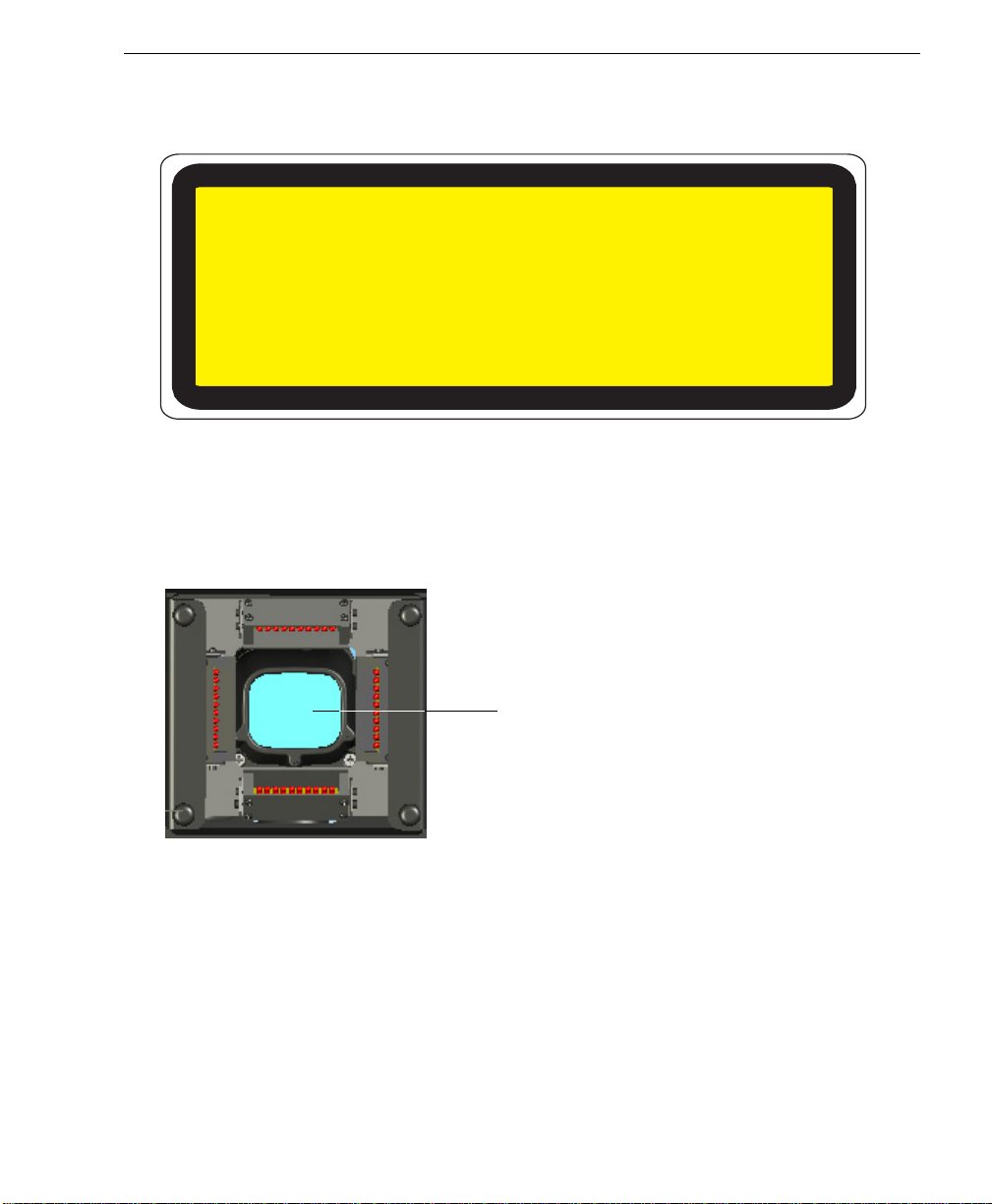
• Viewing the Quadrus Verifier’s LED output with optical instruments such as magnifiers,
eye loupes, or microscopes within a distance of 100 mm could cause serious eye injury.
• Maximum LED light output: 648 cd
• Wavelength: 464 nm; 518 nm; 635 nm
• Location of the Quadrus Verifier’s LED aperture window:
LED Aperture Window
CAUTION: Use of controls or adjustments or performance of procedures other than
•
those specified herein may result in hazardous radiation exposure.
Quadrus Verifier User’s Manual xi
Page 12
Warning and Caution Summary
Warning and Caution Summary (cont.)
WARNING
LED RADIATION
DO NOT STARE INTO BEAM
CLASS 2 LED PRODUCT
Max Power: 67mW Wavelength: 660 nm
IEC 60825-1:1994+A1:2002+A2:2001
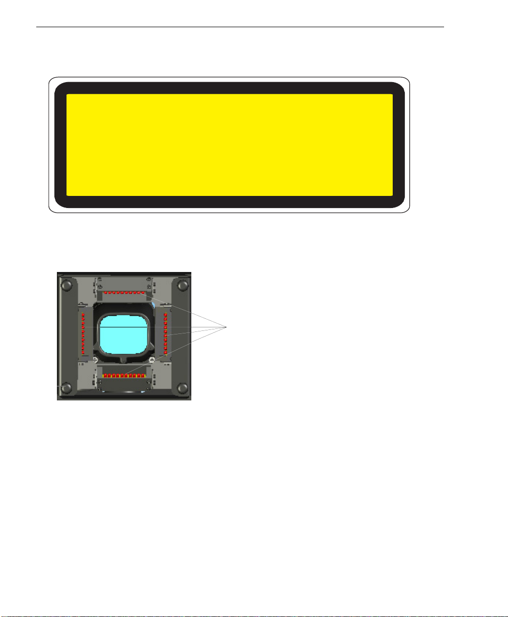
• Max Power: 67 mW
• Wavelength: 660 nm
• Location of the Quadrus Verifier’s LED array:
LED Array
CAUTION: Use of controls or adjustments or performance of procedures other than
•
those specified herein may result in hazardous radiation exposure .
xii Quadrus Verifier User’s Manual
Page 13

1 Quick Start
Contents
Step 1 Check Required Hardware............................................................. ... ... ............................. 1-2
Step 2 Connect the System.......................................................................................................... 1-3
Step 3 Install ESP.........................................................................................................................1-4
Step 4 Select Model..................................................................................................................... 1-5
Step 5 Select Communications Protocol......................................................................................1-6
Step 6 Position Verifier and Symbol.............................................................................................1-7
Step 7 Locate Symbol .................................................................... ... .. .........................................1-8
Step 8 Calibrate Reflectance....................................................................................................... 1-9
Step 9 Set Verification Parameters........................................................................................... 1-10
Step 10 Verifiy Symbol.................................... ... ................................................................ ....... 1-11
Step 11 Generate and Save Verification Report ........................................................................1-14
This section is designed to get your Verifier up and running quickly so yo u can get a sense
of its capabilities and test sample symbols.
Detailed setup information for installing the Verifier in your application can be obtained in
the subsequent sections.
Quadrus Verifier User’s Manual 1-1
Page 14

Check Required Hardware
Step 1 — Check Required Hardware
Hardware Required
Caution: Be sure that all cables are connected BEFORE applying power
to the system. Always power down BEFORE disconnecting any cables.
Item Description Part Number
1 Quadrus Verifier FIS-6700-100XG
2 IB-150 Kit Included with Verifier
3 Power Supply Included with Verifier
4 Illumination Power Supply Included with Verifier
5 Light Control Cable Included with Verifier
6 Quadrus EZ Stand (not shown) Included with Verifier
7 Monitor Kit 98-000096-01
8 Object Detector 99-000017-01
1-2 Quadrus Verifier User’s Manual
Page 15
Step 2 — Connect the System
1
Hardware Configuration
Quick Start
Caution: Be sure that all cables are connected BEFORE applying power
to the system. Always power down BEFORE disconnecting any cables.
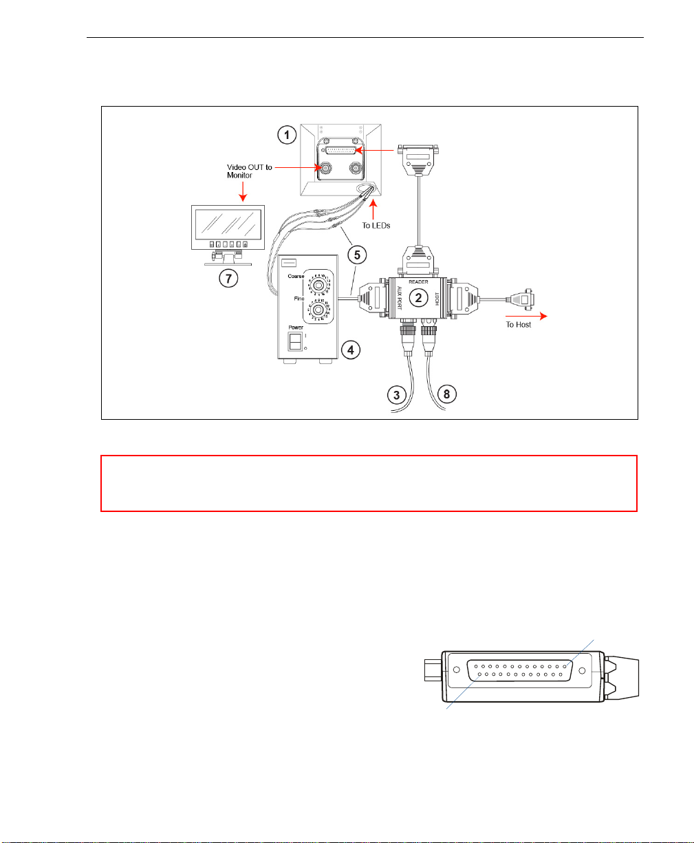
Connecting to a Host by RS-232
1. Connect the Verifier to the IB-150 Kit.
2. Connect the IB-150 Kit host cable to the host.
3. Connect the Lighting Power Supply to the lighting chamber.
4. Connect the main power supply and cycle power to the Verifier.
Note: When wiring the IB-150 Kit to a host
with a 25-pin host connector, cross p ins 2
and 3. When wiring the interface box to a
host with a 9-pin host connector, do NOT
cross pins 2 and 3.
Connecting to a Host by TCP/IP
See Chapter 16, Ethernet.
Quadrus Verifier User’s Manual 1-3
25
Side View of IB-150 showing Host
25-pin Socket Connection
Page 16

Install ESP
Step 3 — Install ESP
Easy Setup Program (ESP) is Microscan’s proprietary setup and testin g application . The
purpose of ESP is to provide a quick and easy way to set up and configure Microscan
products.
When the Quadrus V erifier is co nnected to a host com puter (Windows V ist a, XP, or 2000),
ESP can be used to set up communication with a host, configure various firmware settings,
and control verification processes.
If installing from a Microscan Tools CD:
1. Insert the Microscan Tools CD in your computer’s CD drive.
2. Choose ESP Software from the main menu.
3. Select the Current Version of ESP and follow the file download prompts.
If downloading from the web:
1. Go to http://www.microscan.com/downloadcenter
2. Create a new “myMicroscan” member account or, if you are already a member, enter
your user name and password.
3. Click the Download Software link and extract the latest version of ESP to a directory
of your choice. Note where your ESP.exe file is stored on your hard drive.
4. At the end of the installation process, the following icon will appear on your desktop:
5. Click the ESP icon to start the program.
System Requirements for ESP
• 166 MHz Pentium processor (recommended)
• Windows Vista, XP, or 2000 operating system
• Internet Explorer 5.0 or higher
• 64 MB minimum RAM
• 40 MB minimum disk space
1-4 Quadrus Verifier User’s Manual
Page 17
Step 4 — Select Model
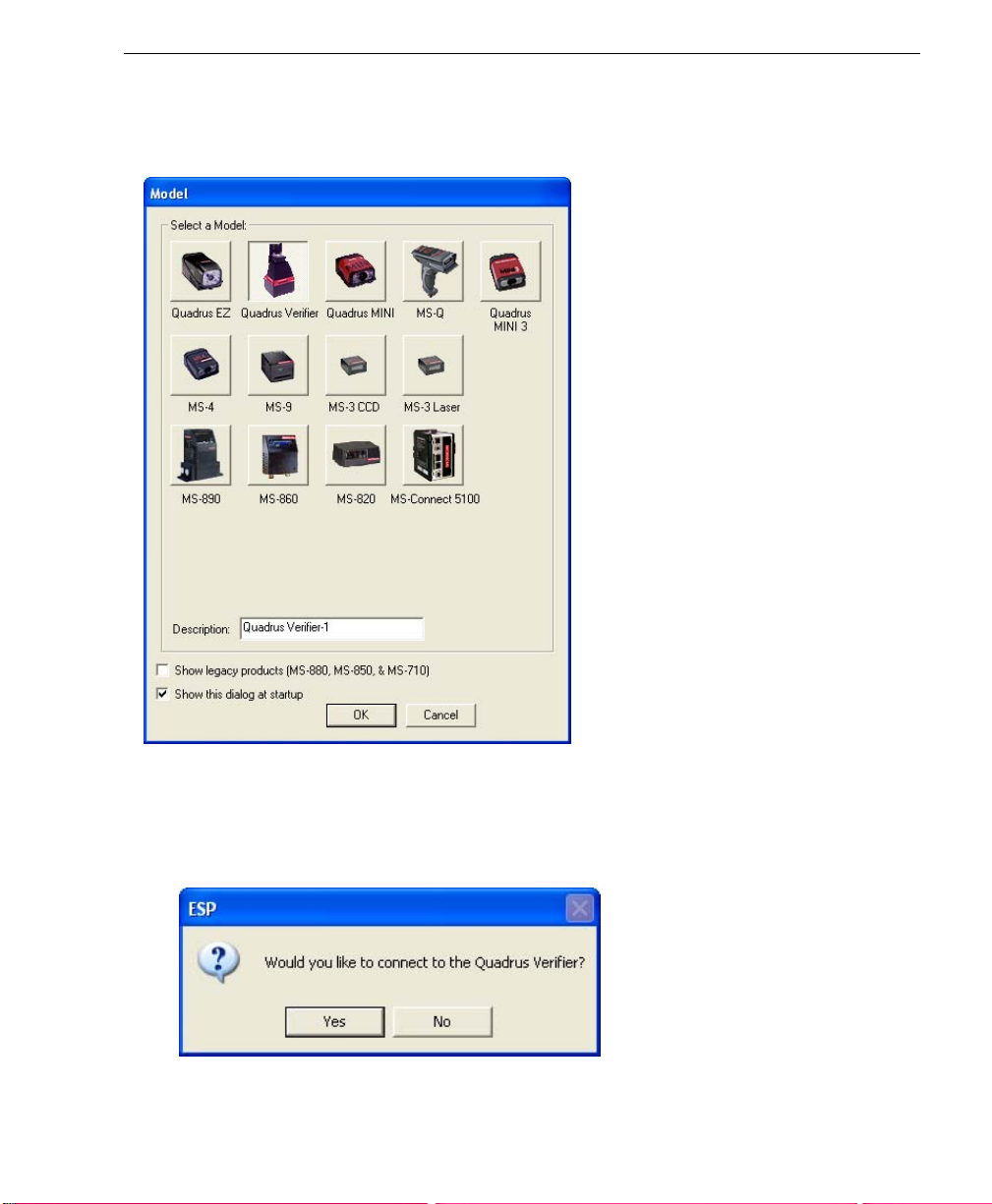
When you start ESP, the following menu will appear:
Quick Start
1. Click the button showing the Quadrus Verifier.
2. Click OK.
3. Note: You can also simply double-click the Quadrus Verifier button to make your
selection.
4. Click Yes when the following dialog box appears:
Note: If you need to select another model later, you can find it in Application Mode
under Model on the menu toolbar.
Quadrus Verifier User’s Manual 1-5
Page 18
Select Communications Protocol
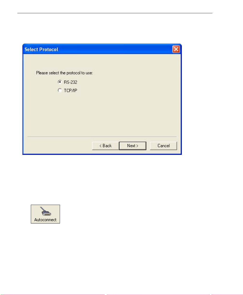
Step 5 — Select Communications Protocol
When the following dialog appears, make your selection and click Next.
RS-232
1. In the RS-232 dialog, if your communications port is not the default COM1, use the
dropdown menu to change your communications port.
2. Click Connect.
3. If the connection fails, click the Autoconnect button, select a different communications
port, and try again.
Note: If your host settings cannot be changed to match the Verifier’s settings, check the
Force Connect box.
TCP/IP
See Chapter 16, Ethernet.
1-6 Quadrus Verifier User’s Manual
Page 19
Quick Start
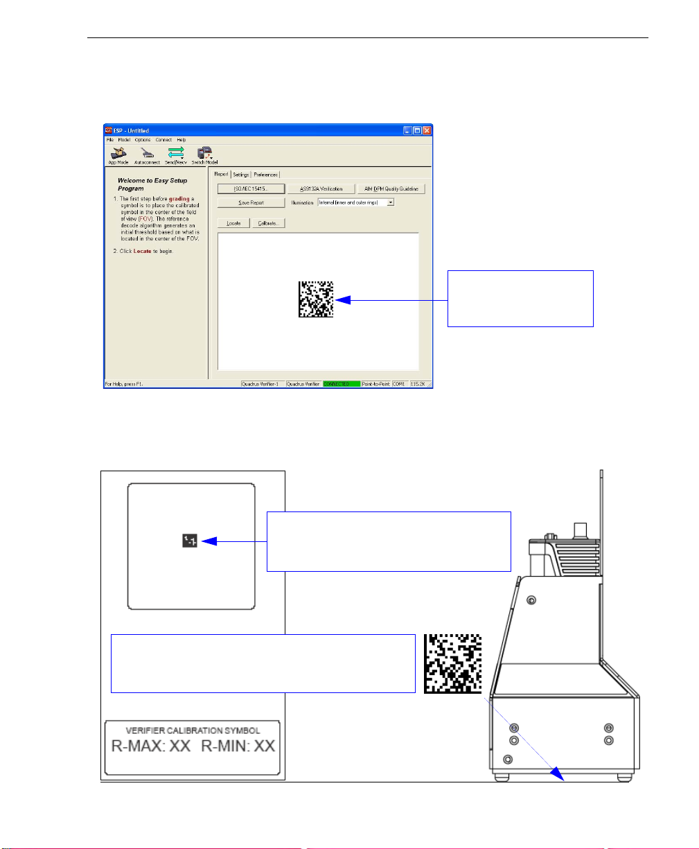
Step 6 — Position Verifier and Symbol
When you connect to
The Quadrus Verifier comes with a reference card that features a Verifier Calibration
Symbol and two numbers--the minimum and maximum reflectance values for ISO/IEC
15415 and AIM DPM Reflectance Calibration. Keep this card in a safe place! It is the
Verifier’s most critical setup tool.
ESP
, the first thing you will see is the
Report
tab of the
This view allows the
user to center the symbol
before calibrating.
Verification
view.
Use the symbol provided at the top of the
Verifier Calibration Symbol card to perform
Reflectance Calibration.
Place the symbol at the center of the field of view. Be
sure the plane of the symbol is as close to perpendicular
as possible relative to the Verifier’s orientation.
Quadrus Verifier User’s Manual 1-7
Page 20
Locate Symbol
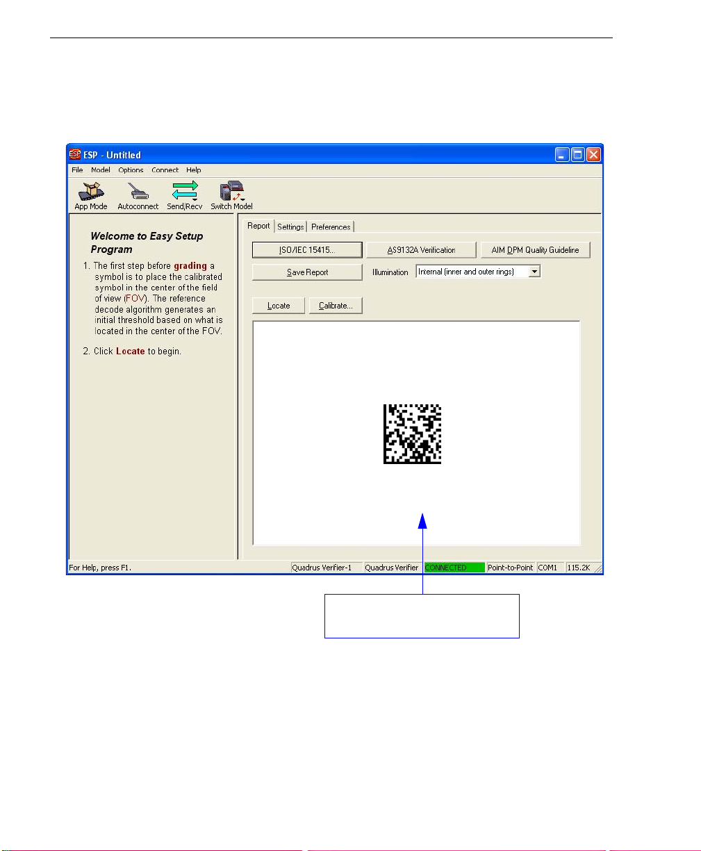
Step 7 — Locate Symbol
After you place the Verifier Calibration Symbol beneath the Verifier’s lighting chamber,
click the Locate button. You will see a video representation of the Verifier’s field of view.
This view allows the user to center
the symbol before calibrating.
1-8 Quadrus Verifier User’s Manual
Page 21
Quick Start
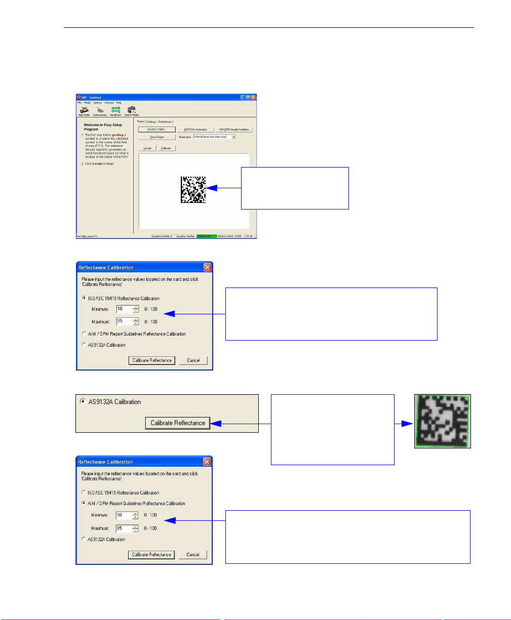
Step 8 — Calibrate Reflectance
Move the symbol to the approximate center of the field of view before beginning calibration.
This view allows the
user to center the symbol
before calibrating.
ISO/IEC 15415 Verification
For ISO/IEC 15415 Reflectance Calibration, use
the spin boxes in the Reflectance Calibration dialog
to set a min. and max. value that match those on the
reference card and then click Calibrate Reflectance.
AS9132 Verification
For AS9132 calibration,
select the corresponding
radio button and click
Reflectance
AIM DPM Verification
For AIM DPM Reflect ance Calib ration, use the spin boxes in
the Reflectance Calibration dialog (as you would for ISO/IEC
15415) to set a min. and max. value that match those on the
reference card and then click Calibrate Reflectance.
Quadrus Verifier User’s Manual 1-9
will appear around the symbol
after calibration.
Calibrate
. A green border
Page 22
Set Verification Parameters
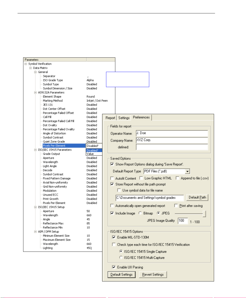
Step 9 — Set Verification Parameters
Once the Verifier is calibrated, you will need to set the parameters for your chosen verification
process. To set these parameters, click the Settings tab in the Verification view.
Configure each setting as appropriate for your application before you begin verification.
Data Matrix symbol
verification settings.
Choose report output characteristics using
the Preferences dialog (shown below).
1-10 Quadrus Verifier User’s Manual
Page 23
Quick Start
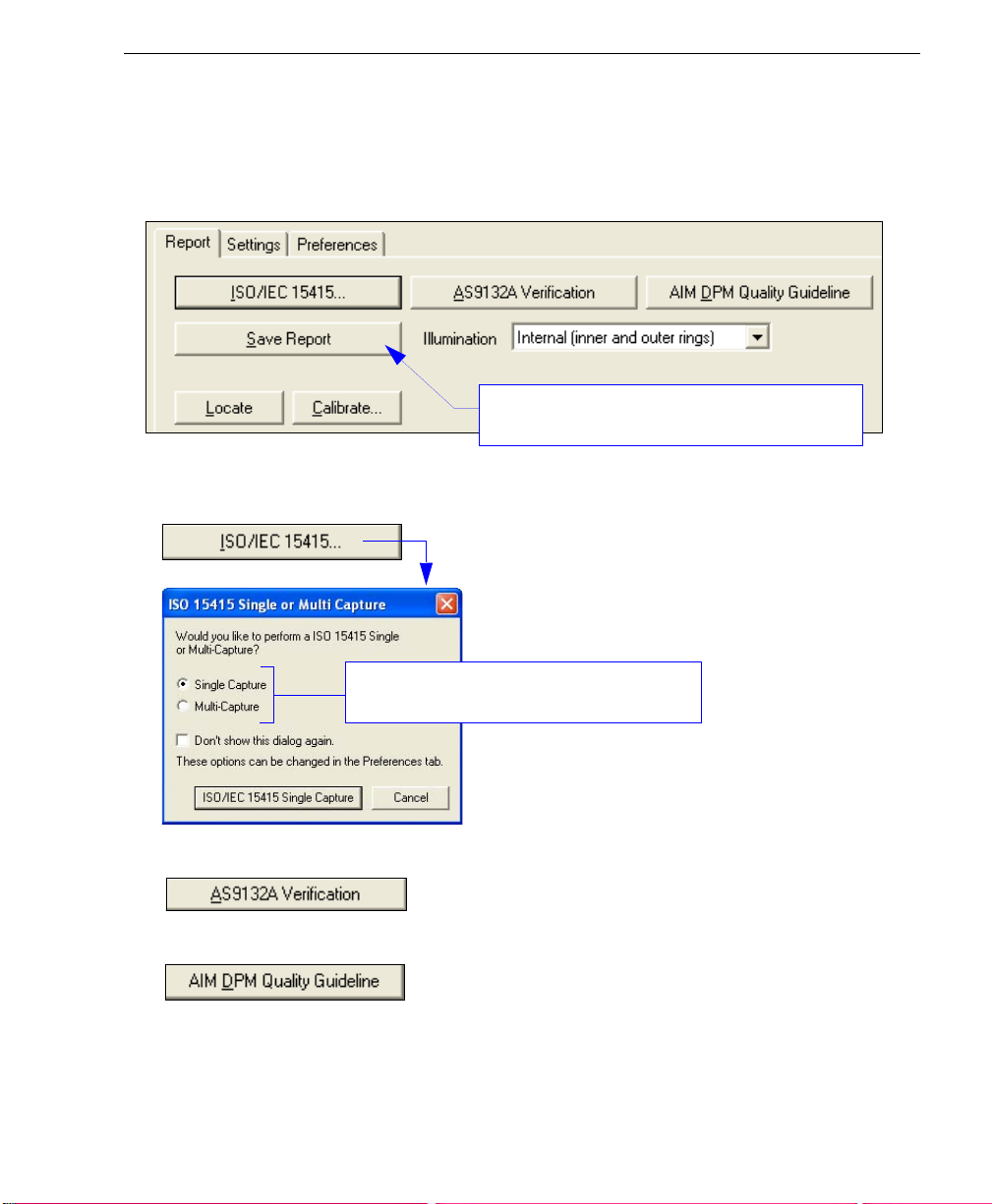
Step 10 — Verify Symbol
When you have finished setting and saving verification parameters and output preferences,
move to the Report tab and click th e button that corresponds to the type of verification
routine you need to perform.
Save Report is explained in greater detail in Step
11, Generate and Save Verification Report.
• For ISO/IEC 15415 Verification, click ISO/IEC 15415... and then select Single Capture
or Multi-Capture when the ISO 15415 Single or Multi-Capture dialog appears.
Select the desired capture process for ISO/IEC
15415 verification.
• For AS9132 Verification, click AS9132A Verification.
• For AIM DPM Verification, click AIM DPM Quality Guideline.
Verification result s are displayed in the viewing area at the lower right of the Verification
view.
Quadrus Verifier User’s Manual 1-11
Page 24
Verify Symbol
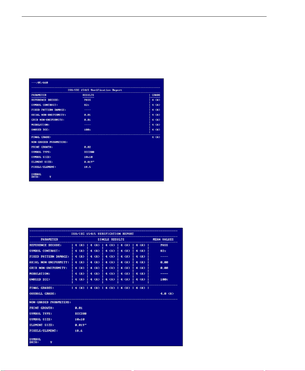
ISO/IEC 15415 Single Capture Verification Results
The ISO/IEC 15415 Single Capture results show data concerning the reference decode
algorithm, symbol contrast, fixed pattern damage, axial and grid non-uniformity, modulation,
unused error correction capacity, print growth, symbology type, symbol size, element size,
and pixels per element. All but the last four parameters are given a numeric and alphabetical
grade.
ISO/IEC 15415 Multi-Capture Verification Results
The
ISO/IEC Multi -Cap ture
but
Multi-Capture
throughout a full 360° rotation. The overall symbol grade is based on an arithmetic mean of
the results from the five reads.
results are determined only after the symbol is read at five 72° intervals
parameters are the same as those for
ISO/IEC Single Capture
,
1-12 Quadrus Verifier User’s Manual
Page 25
Quick Start
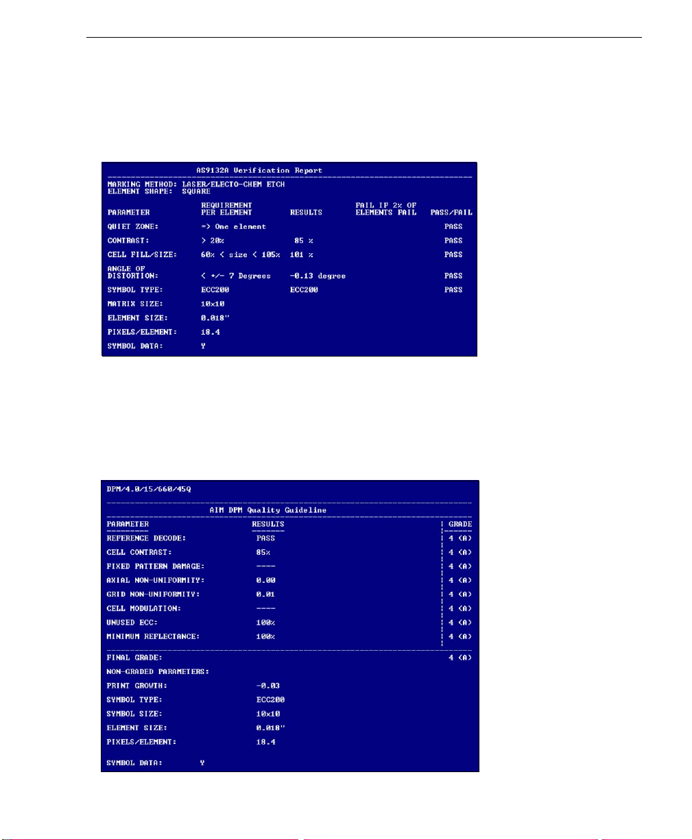
AS9132 Verification Results
The AS9132 results show data concerning marking method, element shape, quiet zone,
contrast, cell fill, cell size, dot ovality, dot shape, dot center offset, dot spacing, angle of
distortion, symbology type, matrix size, and pixels per element. Symbol assessment is on
a pass/fail basis.
AIM DPM Verification Results
The AIM DPM results show data concerning reference decode algorithm, cell contrast,
fixed pattern damage, axial and grid non-uniformity, cell modulation, unused error correction
capacity, minimum reflectance, print growth, symbol type, symbol size, element size, and
pixels per element. All but the last five parameters are given a numeric and al phabetical
grade.
Quadrus Verifier User’s Manual 1-13
Page 26
Generate and Save Verification Report
Step 11 — Generate and Save Verification Report
To generate a report containing your verification results, click the Save Report... button.
The
Grade Report Options
dialog.
After report options are chosen, determine where the report will be stored on the host hard
drive in the
Save As
dialog. Once you have specified a file name and clicked
begin transferring report data to the chosen directory location.
When the data transfer is complete, the verification report will appear in the chosen location
on your hard drive. Open the folder and click on the report file. Y ou can choose PDF, HTML,
RTF, or CSV format for report output.
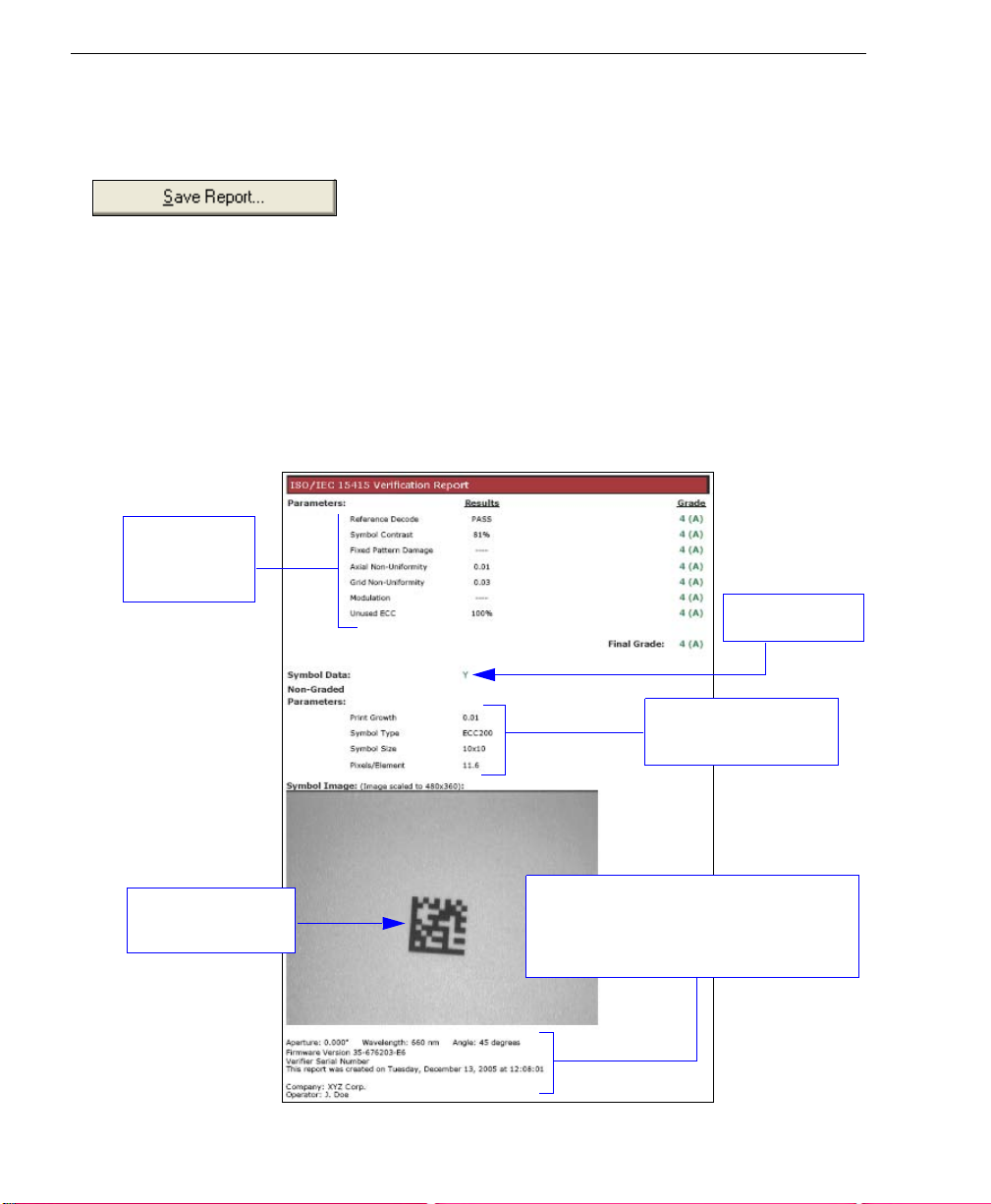
ISO/IEC 15415 Single Capture Verification Report
Verification
results and
grades.
dialog will appear, unless you have disabled it in the
Save, ESP
Preferences
will
Symbol data.
Data for non-graded
parameters.
Captured symbol
image.
Note: PDF version shown here.
Reference data: Verifier firmware version,
Verifier serial number, report creation
date, ESP version, company name, and
operator name.
1-14 Quadrus Verifier User’s Manual
Page 27
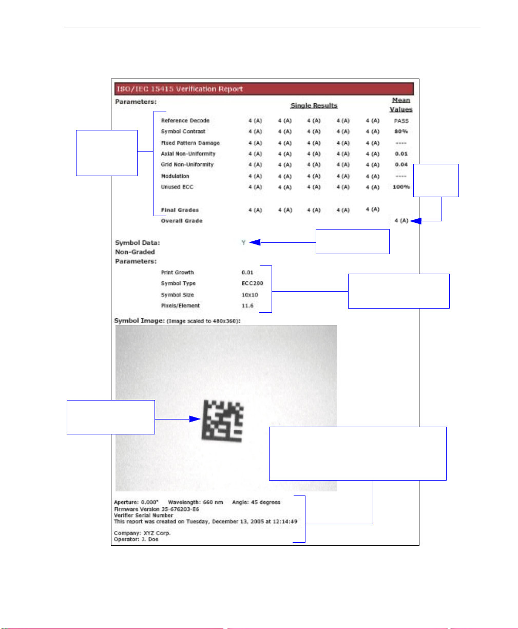
ISO/IEC 15415 Multi-Capture Verification Report
Grades for
individual
captures.
Symbol data.
Data for non-graded
parameters.
Quick Start
Overall
grade.
Captured symbol
image.
Reference data: Verifier firmware version,
Verifier serial number, report creation
date, ESP version, company name, and
operator name.
Note: PDF version shown here.
Quadrus Verifier User’s Manual 1-15
Page 28
Generate and Save Verification Report
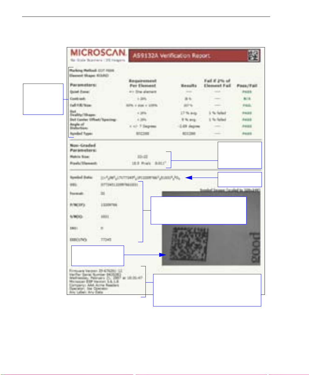
AS9132 Verification Report
Verification
results and
pass / fail
grades.
Data for
non-graded
parameters.
Symbol data.
Parsed UII data. UII Parsing must be
enabled in Preferences for parsed UII
data to appear in verification reports.
Captured symbol
image.
Reference data: Verifier firmware version,
Verifier serial number, report creation
date, ESP version, company name, and
operator name.
Note: PDF version shown here.
1-16 Quadrus Verifier User’s Manual
Page 29
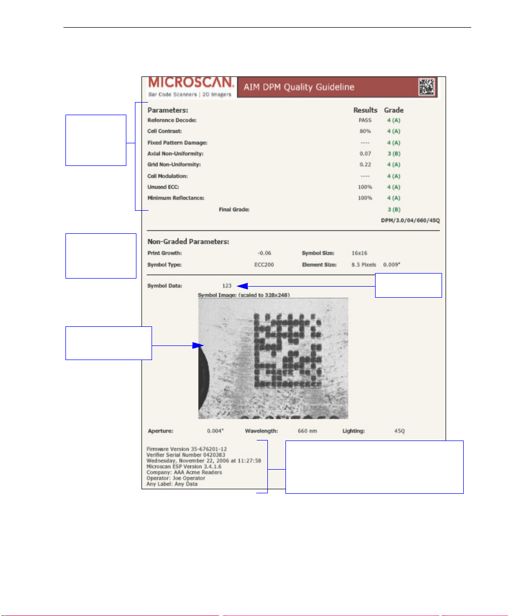
AIM DPM Verification Report
Verification
results and
pass / fail
grades.
Data for
non-graded
parameters.
Quick Start
Symbol data.
Captured symbol
image.
Reference data: Verifier firmware version,
Verifier serial number, report creation
date, ESP version, company name, and
operator name.
Note: PDF version shown here.
Quadrus Verifier User’s Manual 1-17
Page 30

Generate and Save Verification Report
1-18 Quadrus Verifier User’s Manual
Page 31

2 Using ESP
Contents
Verification....................................................................................................................................2-2
Application Mode..................................... ......................................................................................2-3
Menu Toolbar.................................................. ... ... ........................................................................2-4
View ............................................................................................................................................2-11
Navigating in ESP................................ ........................................................ ...............................2-12
Send/Receive Options ................................................................................................................2-13
This section is designed to help you understa nd the structure, element s, and application of
ESP.
When you open
from the
there, you can enter
(V erification, Communications, Read Cycle, Symbologies, I/O Parameters, Symbol
Quality , Matchcode, and Diagnostics), a Camera setup interface, a Terminal interface, a
Utilities interface, and an Output Format interface.
ESP can be used to configure the Quadrus Verifier in three different ways:
•
• Graphic User Interfaces: Settings can be configured using such point-and-click tools
• Terminal: ESP’s Terminal interface allows you to send serial configuration and utility
Options
Tree Controls:
specific element of Verifier operation. For example, the
Host Port Connections
Bits
, and
as radio buttons, zoom in/zoom out sliders, spin boxes, check boxe s, and drag-and-drop
functions.
commands directly to the Verifier by typing them in the provided text field.
ESP
, unless otherwise specified in the
heading on the menu toolbar, you will enter
Application Mode (App Mode
Each configuration menu contains a list of all option settings that pertain to that
option, and then a list of the sub-options
Data Bits
. Each of these sub-options is configurable by using dropdown menus.
ESP Preferences
EZ Mode
) and access several
Communications
for initial setup. From
Baud Rate, Parity, Stop
dialog accessible
configuration menus
menu shows a
For ESP system requirements, see System Requirements for ESP in Quick Start.
Quadrus Verifier User’s Manual 2-1
Page 32

Verification
Verification
In the Verification view you are pr es en te d with the Locate and Calibrate options. After
connecting to the Verifier, Verification is the first view you will see. You will be provided
with on-screen instructions that will help you with symbol positioning, location, and calibration.
Enter App Mode to
access configuration
trees and other setup
features.
Click Calibrate to begin the initial
calibration routine. Calibration and
grading are explained at the left of
the Verification screen.
Click Locate to activate
video.
Center the symbol in the
field of view .
Locate
When you click Locate, the video view be activated. This allows you to center the candidate
symbol in the Verifier’s field of view before beginning the calibration routine.
Calibrate
Reflectance Calibration is required for ISO/IEC 15415 verification.
Illumination
The
Illumination
view. See Illumination Source for further detail about LED illumination options.
2-2 Quadrus Verifier User’s Manual
dropdown menu allows you to configure LED behavior from the
Verificat ion
Page 33

Using ESP
Application Mode
The Quadrus Verifier can be used as a reader as well as a verifier. ESP’s App Mode
offers complete control of configuration parameters.
From Verification, you can click on the App Mode button to access specific configuration
menus, Utilities tools, Camera setup, Output Format options, and a Terminal window
where serial commands can be entered.
Note: The App Mode and EZ Mode buttons appear in the same position to allow easy
switching between these primary modes.
Camera Setup, Evaluation,
Region of Interest, IP Database,
Dynamic Setup.
Click here for
Click this icon to
return to Verification.
Click here to open
the Terminal view.
Menu toolbar.
Ordered Output
and Output Format
features.
Click on icons in this row
to access configuration
trees like the one at left.
Click the Configuration icon to return to full
App Mode view from Verification, Camera,
Terminal, Utilities, or Output Format.
Decoded symbol data
is shown in this table.
Click Capture and Decode to
read the symbol in the field of
view, and t o see a high resol ution
image capture of the symbol.
Quadrus Verifier User’s Manual 2-3
Page 34

Menu Toolbar
Menu Toolbar
File > New
Whenever New is selected, the default configuration of ESP is
loaded.
Open/Save
When
Save
or
Save As
to the host computer’s hard drive and available whenever the same
file is selected under
Important: When you save menu changes to your hard drive,
these changes are not saved to your Verifier. The illustration
below shows how settings can be saved and received between
ESP and the Verifier, and ESP and the host hard drive.
(Receive Verifier
Settings)
is selected, the
Open
.
(Save to Verifier)
ESP
configuration is saved
Import/Export
Import converts the ASCII settings from a text file to ESP configuration settings.
Export converts the active ESP configuration settings to an ASCII text file.
2-4 Quadrus Verifier User’s Manual
Page 35

Model
In
Model
you can select any of the models shown in
menu. When you choose another model, your current connection to your
present model will be terminated.
To connect to another model, select New Model, choose a new
model from the menu, and click OK.
ESP
’s
model
Using ESP
Note: All the models you have enabled by selecting will continue to appear in the Model
menu and that the same menu is repeated when clicking the Switch Model icon.
When you save your ESP file, you will be saving the settings of all the models defined in a
single ESP file.
Quadrus Verifier User’s Manual 2-5
Page 36

Menu Toolbar
Options
The Options menu allows you to save memos and set up ESP
Preferences.
Note: Preferences will be saved and loaded into ESP when
ESP is opened next, whether or not you save the ESP file.
Preferences
General Tab
Reload Last File
At startup, reloads the last file saved to the host computer’s hard drive.
Show Model Prompt
At startup, remembers the last connected model and displays it in the Connecting... dialog
whenever you attempt to connect.
Show Connect Prompt
At startup, displays the Would you like to connect...? prompt.
Receive After Connect
At startup, loads the Verifier’s settings into ESP. (This is not recommended if you want to
preserve your ESP settings for future use.)
Enable ‘Send and Save as Customer Defaults’
At startup, enables the Send and Save as Customer Defaults option in the Send/Recv
command.
2-6 Quadrus Verifier User’s Manual
Page 37

Terminal Tab
Using ESP
When Show Non-Printable Characters is checked, characters such as “CRLF” will be
displayed in the Terminal window. When Enhanced Format is checked, the characters
are displayed with more detailed formatting.
Change Keyboard Macros
In this dialog you can first select the function key and then enter your macro keystrokes in the
associated key map. For example, to make
character, select
whenever the
Change Font
Allows you to modify the font used for decode data received from the V erifier on the
screen.
Change Echo Font
Allows you to modify the font used for command characters typed into the Terminal view.
Quadrus Verifier User’s Manual 2-7
F5
, and then in the
Ctrl-F5
keystroke is pressed, the trigger character will start the read cycle.
Ctrl
Ctrl-F5
row, enter
the keystroke to enable, send a trigger
<trigger character>
and click OK. Then
Terminal
Page 38

Menu Toolbar
Bar Code Options Tab
The Bar Code Options dialog allows you to set the size (in mils) of user- created symbo ls.
Sizing Information
Sets the bar width (in thousands of an inch ) of user-created symbols. A bar width of 14 is
0.014 inches.
2-8 Quadrus Verifier User’s Manual
Page 39

Advanced Tab
Using ESP
The Auto Sync dialog at the top of the Advanced tab allows you to determine whether
Auto Sync will be automatically enabled in sections of ESP where it is used, or if it will ask
you before it enables Auto Sync functions.
Always Ask Before Auto Sync Occurs
If you check this option box, you are then able to determine what specific Auto Sync
functions will be enabled. Receive Settings from the Reader will automatically send
the Verifier’s settings to ESP when Auto Sync is enabled. Send ESP Settings to the
Reader will automatically send all Verifier configuration settings chosen in ESP to the
Verifier. Do Not Send or Receive Settings creates a condition in which Auto Sync will
not send Verifier settings to ESP, or send ESP settings to the Verifier.
Send XON with Autoconnect
Sends an
routine.
Quadrus Verifier User’s Manual 2-9
XON (Begin Transmission
) command to the Verifier before starting the
Autoconnect
Page 40

Menu Toolbar
Document Memo
The information you type in the Document Memo field will appear in a context-sensitive text
box whenever your cursor hovers over the Document Memo item on the Options menu.
Model Memo
Similar to Document Memo, the information you type in the Model Memo field will appear
in a context-sensitive text box whenever your cursor hovers over the Model Memo item on
the Options menu. Memos created in Model Memo are specific to the mod el en able d
when the message was created.
Note:
Memos must be saved in a
If you do not save your current session, any memos that you have entered during the session
will be discarded, and will be unavailable in your next session.
2-10 Quadrus Verifier User’s Manual
.esp
file if you want them to available in your next session.
Page 41

Using ESP
View
The View menu allows you to mo ve quickly b etwee n interface s without using th e icon
buttons on the App Mode toolbar. It also allows you to access the Bar Code Dialog.
Bar Code Dialog
In the Bar Code Dialog you can create symbols by typing the text you wish to encode.
This is a useful tool for creating configuration symbols, allowing you to configure your
Verifier by reading the symbols you create.
Drag specific configuration
values from the control tree
directly into this field to
encode new symbols.
Choose a spatial
orientation for the
new symbol.
Set a humanreadable caption
for the symbol
that matches the
encoded data, or
write your own
caption.
The symbol you create
will be displayed in the
field at the bottom of the
Bar Code Dialog.
Quadrus Verifier User’s Manual 2-11
Page 42

Navigating in ESP
Navigating in ESP
To change Verifier settings, or to access the Configuration, Camera , Terminal, Utilities, or
Output Format views, click the App Mode button.
To return to Verification, click the Verification button.
To make changes to configuration settings in the control trees:
Open or close the full contents of a control tree by holding down the Alt key and single-clicking here.
The x denotes the
default option setting.
• Left click on
the + to expand
menu items.
• Double-click the desired parameter and single-
click in the selection box to view options.
• Place your cursor in the selection box, scroll
down to the setting you want to change, and
single-click the setting.
• Left click again on the open screen to complete
the selection.
• Right click on the open screen and select Save to
Reader to implement the command in the Verifier. You
can send the command without saving it, or you can send
and save the command simultaneously.
2-12 Quadrus Verifier User’s Manual
Page 43

Using ESP
Send/Receive Options
To access Receive, Save and Default options, click the Send/Recv button. You can also
access these options by right-clicking in any of the configuration views.
Receiving
From the Send/Recv menu, select Receive Reader Settings.
Caution: Do not select this option if you do not want to upload the Verifier’s settings. For
example, if your ESP file has a number of custom settings that you want to maintain and
download into the Verifier, these settings would be lost by choosing Yes.
This is useful if you want to receive (upload) the Verifier’s settings and save them as a file
for future use. For example, if your Verifier has settings that you do not want to change,
choosing Yes would allow you to load those settings to ESP and save them in a ESP file
for later retrieval.
Receiving the Verifier’s settings will also assure that you will not be subsequently saving
any unwanted changes that you or someone else has made previously in ESP.
Saving
• Send, No Save (<A>)
Saves ESP settings
to current memory.
• Send and Save (<Z>)
Activates all changes
in current memory
and saves settings
for power-on.
• Send and Save as Customer Defaults (<Zc>)
Saves your own default settings for quick retrieval with a <Zrc> command.
This option will be visible only if you have checked
Defaults’
Quadrus Verifier User’s Manual 2-13
in the
ESP Preferences
dialog.
Enable ‘Send and Save as Customer
Page 44

Send/Receive Options
Defaulting
When you select Default Current Menu Settings or Default all Settings, you are only
defaulting the ESP settings.
Advanced Options
Send Current View
This is the same as
Reader
that only the commands in the
current configuration tree are sent.
>
Send No Save
Send Current Command
This is the same as
View
, except that it saves only
the command that is currently
selected.
Add / Remove Exception
After you perform a Receive Reader Settings command1 and you click on the Add
Exception option, you may see a list of serial commands. These are commands that may
be in your Verifier’s firmware, but not included in, or different from, your current version of
ESP.
You can edit these commands by double-clicking on them and changing them as needed.
It is important to note that these commands will be saved to your Verifier whenever you
send a Save to Reader command, or an <A> or a <Z> command.
Also, if there is a corresponding ESP menu item, the ESP Value column for that item will
be blank following a Receive Reader Settings command.
Save to
except
Send Current
1. From the Send/Recv button or by right-clicking from within the configuration trees.
2-14 Quadrus Verifier User’s Manual
Page 45

3 Verification
Verification Serial Commands......................................................................................................3-2
Verification Operational Commands............................................................................................. 3-2
Overview of Verification................................................................................................................ 3-3
ISO/IEC 15415 Evaluation Parameters........................................................................................ 3-5
AS9132 Evaluation Parameters ................................................................................................... 3-7
AIM DPM Evaluation Parameters...............................................................................................3-10
General Verification Serial Output..............................................................................................3-12
General Verification Output by ESP........................................................................................... 3-17
ISO/IEC 15415 Verification Setup..............................................................................................3-19
ISO/IEC 15415 Verification Setup by ESP.................................................................................3-21
ISO/IEC 15415 Serial Output .....................................................................................................3-23
ISO/IEC 15415 Output by ESP...................................................................................................3-33
AIM DPM Verification Setup....................................................................................................... 3-40
AIM DPM Verification Setup by ESP..........................................................................................3-42
ISO/IEC 15415 Verification by Serial Command........................................................................ 3-44
AS9132/JES 131 Marking Method .............................................................................................3-49
AS9132/JES 131 Marking Method by ESP ................................................................................3-51
AS9132 Serial Output................................................................................................................. 3-53
AS9
132 Output by ESP.............................................................................................................. 3-62
AS9132 Verification by Serial Command ...................................................................................3-67
AIM DPM Verification by Serial Command................................................................................. 3-68
Verification by ESP..................................................................................................................... 3-70
Contents
This section describes the verification process, including specification requirements,
software configuration, step-by-step procedures, and report output.
Quadrus Verifier User’s Manual 3-1
Page 46

Verification Serial Commands
Verification Serial Commands
ISO/IEC 15415 Verification Setup <K531,aperture,wavelength,angle,reflectance
maximum,reflectance minimum>
AIM DPM Verification Setup <K532,minimum element size,maximum element
size,wavelength,lighting>
General Verification Serial Output <K708,separator character,unused (0),ISO grade
type,symbol type,symbol dimension/size>
AS9132/JES 131 Marking Method
AS9132 Serial Output
ISO/IEC 15415 Serial Output <K756,grade,aperture value,wavelength value,light
<K711,element shape,marking method,JES 131>
<
K712,
dot center offset,percentage failed offset,
cell fill,percentage failed cell fill,dot ovality,percentage
failed ovality ,angle of distortion,symbol contrast
zone grade,pixels per element value>
angle value,decode grade,symbol contrast,fixed
pattern damage grade,axial non-uniformity,grid
non-uniformity,modulation grade,unused error
correction,
value>
print growth value,pixels per element
Verification Operational Commands
ISO/IEC 15415 Reflectance Calibration <@VER>
ISO/IEC 15415 Single Capture Verification <V1>
ISO/IEC 15415 Multi-Capture Verification <V2>
AS9132 Verification <V3>
AIM DPM Reflectance Calibration <@AIMDPM,R-max,R-min>
AIM DPM Verification <V4>
,quiet
3-2 Quadrus Verifier User’s Manual
Page 47

Verification
Overview of Verification
The use of Data Matrix symbols in ID automation applications requires high-quality marks.
The purpose of verification is to ensure reliability and consistency of symbols, based on
the strict criteria outlined in the AS9132 and ISO/IEC 15415 standards and the AIM DPM
quality guideline. The Quadrus Verifier is designed to evaluate marks based on the specific
parameters in AS9132, ISO/IEC 15415, and AIM DPM.
AS9132
The AS9132 standard specifies uniform quality and technical requirements for direct part
marking with Data Matrix symbols. Direct part marking can be achieved by a variety of
means, including ink jet, dot peen, laser etch, and chemical etch.
Note: AS9132 and AS9132A are used interchangeably throughout this documentation.
“AS9132” is the name of the specification, and the suf fix “A” de notes the current pu blished
version of the specification.
ISO/IEC 15415
The ISO/IEC 15415 standard specifies the methodologies for measuring, evaluating, and
grading 2D symbol characteristics in orde r to provide an overall symbol grade.
AIM DPM
The AIM DPM quality guideline assesses direct part mark quality for a number of parameters,
including cell contrast, fixed pattern damage, axial and grid non-uniformity, cell modulation,
unused error correction capacity, and minimum reflectance. Direct part marking can be
achieved by a variety of means, including ink jet, dot peen, laser etch, and chemical etch.
AIM DPM is called out in MIL-STD-130N as the preferred guide for ensuring symbol quality
and reliability.
MIL-STD-130N
MIL-STD-130N is a standard for implementing ID automation processes to track United
States Department of Defense property.
The DoD’s primary means of parts traceability is the IUID initiative. IUID, which stands for
“Item Unique Identification”, is a system of establishing unique item identifiers (UIIs) by
assigning a machine-readable character string or number to an item (a single hardware
component or grouping of subassemblies), thereby distinguishing it from other items.
Tracing items in this way requires the use of reliable symbols, whether in the form of
printed labels or marks applied directly to parts. MIL-STD-130N calls out AIM DPM as
the preferred standard for ensuring symbol quality and reliability.
Quadrus Verifier User’s Manual 3-3
Page 48

Overview of Verification
ISO/IEC 15426-2 Verifier Certification
ISO/IEC 15426-2 is a verifier conformance standard that is referenced in the introduction
to the ISO/IEC 15415 specification. Conformance to ISO/IEC 15426-2 is required for
certification as a true Data Matrix verifier.
Why is Verifier re-calibration important?
Like any measurement device, the Quadrus Verifier requires regular maintenance and
calibration to ensu re relia b le an d ac cu ra te ope ra tio n ov er time .
How often does the Verifier need to be re-calibrated / re-certified?
Microscan recommends that the Quadrus Verifier be re-calibrated and re-certified once
every year.
Important: Even if the Verifier has not been used during the first year of ownership, it
should still be sent to Microscan for re-calibration one year from the date of original factory
calibration
What is the process for Verifier re-calibration / re-certification?
Schedule a return under the SRO (Service Return Order) process. Cont act the Microscan
Service Department at 425.226.5700 to initiate the SRO process.
.
3-4 Quadrus Verifier User’s Manual
Page 49

ISO/IEC 15415 Evaluation Parameters
Symbol Contrast is the value difference between light and dark symbol
elements, and between the quiet zone and perimeter elements.
This example shows a low-contrast symbol. The light and dark elements
are too close in value, which undermines readability.
Fixed Pattern Damage refers to finder pattern and clock pattern
damage.
Notice the missing elements in the clock pattern and the damaged
L-pattern in the example symbol.
Axial Non-Uniformity is the amount of deviation along the symbol’s major axes.
In this example, the symbol’s Y -axis dimension is clearly greater than its X-axis
dimension.
Y
X
The reference
decode algorithm
plots the symbol’s
grid intersections
and compares
them to an ideal grid.
The largest vector deviation on the grid
determines the Grid Non-Uniformity grade.
Grid Non-Uniformity refers to a symbol’s cell deviation from the ideal grid
of a theoretical “perfect symbol”.
The Data Matrix reference decode algorithm is applied to a binarized image
of the symbol, comparing its grid intersections to ideal grid intersections. The
greatest distance from an actual to a theoretical grid intersection determines
the Grid Non-Uniformity grade.
Y
X
Actual grid
intersection
Ideal grid
intersection
Vector
deviation
Symbol Detail
Symbol Contrast
Fixed Pattern Damage
Axial Non-Uniformity
Verification
Grid Non-Uniformity
Quadrus Verifier User’s Manual 3-5
Page 50

ISO/IEC 15415 Evaluation Parameters
Modulation refers to the reflectance uniformity of a symbol’s light and dark
elements.
In this example, notice that the light/dark values of some elements are
inconsistent.
Unused Error Correction indicates the amount of available error correction in
a symbol. Error Correction is a method of reconstructing or replacing data that
is lost through symbol damage. 100% Unused Error Correction is ideal.
The example at left is an ECC 200 Data Matrix symbol in good condition. “ECC
200” indicates the error correction level of the symbology. A higher number
indicates more robust error correction capacity.
Overprint
Underprint
Print Growth refers to the deviation (larger or smaller) of actual element size from intended
element size due to printing problems. When a symbol is printed, the ink may “bleed” when it
comes in contact with the substrate, causing an Overprint. If there is not enough ink, or if there
is some other problem with printing equipment, the result may be an Underprint.
This magnified symbol detail contains 4 elements, each with a width of 10 pixels.
Pixels Per Element refers to the number
of pixels in each individual symbol element.
10 pixels
Modulation
Unused Error Correction
Print Growth
Pixels Per Element
3-6 Quadrus Verifier User’s Manual
Page 51

AS9132 Evaluation Parameters
x
A symbol’s Dot Center Offset value indicates the deviation of actual
dot centers from theoretical or “ideal” dot centers.
x
Ideal dot
center
Actual dot
center
The difference between the ideal and actual
dot centers is the Dot Center Offset value.
x
Cell Fill is the percentage of the ideal cell size that the module or
element fills.
The example at left shows dot peen elements that overfill the ideal
cell size. The elements of the dots exceed the cell boundaries.
Dot Ovality is the extent to which round elements deviate from a perfect
circle.
The example at left shows a symbol that woul d rece i ve an un fa vorable
Dot Ovality evaluation.
Ideal dot shape
d
D
Module
If D - d > 20% of nominal module size, then dot ovality
is out of spec with AS9132 requirements.
Dot Center Offset
Cell Fill
Verification
Dot Ovality
Quadrus Verifier User’s Manual 3-7
Page 52

AS9132 Evaluation Parameters
The Angle of Distortion is the symbol’s
deviation from a 90° relation between row
and column.
90
°
90
°
75
°
105
°
X
Y
15
°
Ideal: 90° Row/Column 15° Deviation from Ideal Row/Column
Symbol Contrast is the value difference between light and dark
symbol elements, and between the quiet zone and perimeter
elements.
This example shows a low-contrast symbol. The dark elements
(etched) and the light elements (the substrate’s surface) are too
close in value, which undermines readability.
The Quiet Zone is an unmarked space of at least one element in
width surrounding the symbol, required for symbol readability.
The red box in the example represents the outer perimeter of the
minimum Quiet Zone requirement. The Quiet Zone can be any
amount greater than one element in width, but any Quiet Zone
width less than one element will make the symbol difficult or
impossible to read.
Angle of Distortion
Symbol Contrast
Quiet Zone
3-8 Quadrus Verifier User’s Manual
Page 53

Pixels Per Element
11 pixels
Pixels Per Element refers to the number of pixels in each individual symbol element.
This magnified symbol detail contains 4 elements, each with a width of 11 pixels.
Verification
Quadrus Verifier User’s Manual 3-9
Page 54

AIM DPM Evaluation Parameters
Cell Contrast is the value difference between light and dark symbol elements,
and between the quiet zone and perimeter elements.
This example shows a low-contras t direct p art mark symbol. The light and dark
elements are too close in value, which undermines readability.
Fixed Pattern Damage refers to finder pattern and clock pattern
damage.
Notice the missing elements in the clock pattern and the damaged
L-pattern in the example symbol.
Axial Non-Uniformity is the amount of deviation along the symbol’s major
axes.
In this example, the symbol’s Y-axis dimension is clearly greater than its X-axis
dimension.
Y
X
The reference
decode algorithm
plots the symbol’s
grid intersections
and compares
them to an ideal grid.
The largest vector deviation on the grid
determines the Grid Non-Uniformity grade.
Grid Non-Uniformity refers to a symbol’s cell deviation from the ideal grid
of a theoretical “perfect symbol”.
The Data Matrix reference decode algorithm is applied to a binarized image
of the symbol, comparing its grid intersections to ideal grid intersections. The
greatest distance from an actual to a theoretical grid intersection determines
the Grid Non-Uniformity grade.
Y
X
Actual grid
intersection
Ideal grid
intersection
Vector
deviation
Symbol Detail
AIM DPM Evaluation Parameters
Cell Contrast
Fixed Pattern Damage
Axial Non-Uniformity
Grid Non-Uniformity
3-10 Quadrus Verifier User’s Manual
Page 55

Cell Modulation
Modulation refers to the reflectance uniformity of a symbol’s light and dark
elements.
In this example of a dot peen mark, notice that the light/dark values of some
of the elements are inconsistent.
Unused Error Correction indicates the amount of available error correction
in a symbol. 100% Unused Error Correction is ideal.
Overprint
Underprint
Print Growth refers to the deviation (larger or smaller) of actual element size from intended
element size due to printing problems. When a symbol is printed or chemical etched, the ink or
etching agent may “bleed” when it comes in contact with the substrate, causing an Overprint. If
there is not enough ink, or if there is some other problem with printing or etching equipment, the
result may be an Underprint.
11 pixels
Pixels Per Element refers to the number of pixels in each individual symbol element.
This magnified symbol detail
contains 4 elements, each with
a width of 11 pixels.
Unused Error Correction
Print Growth
Verification
Pixels Per Element
Quadrus Verifier User’s Manual 3-11
Page 56

General Verification Serial Output
General Verification Serial Output
This command allows the user to determine the specific output settings for Separator
Character, ISO Grade Type, Symbol Type, and Symbol Dimension/Size as they
appear in ISO/IEC 15415 and AS9132 verification output.
Separator Character
Definition: Inserts a separator between each field of verification report output.
Serial Cmd:
Default: , (comma)
Options: Any ASCII character except NULL, < , or >.
<
K708,separator character
symbol dimension/size>
,unused (0),ISO grade type,symbol type,
ISO/IEC 15415
Output Example:
symbol_data,2,005,660,45,4,4,075,3,1,0.11,3,0.43,3,2,057,-0.82,
08.7,ECC200,032x032
AS9132 Output
Example:
symbol_data,P,F,045,057,P,002,001,F,-08.20,P,034,P,12.4,ECC200,
018x018
Default Separator Character (comma) highlighted below.
Default Separator Character (comma) highlighted below.
ISO Grade Type
Definition: Determines whether ISO/IEC 15415 grades are in alphabetical or numeric
form.
Note: This setting does not affect AS9 132 output, beca use AS9132 symbol
evaluations are on a pass/fail basis.
Serial Cmd:
Default: Alpha
Options: 0 = Alpha
<
K708,
separator character,
dimension/size
1 = Numeric
unused (0),
>
ISO grade type
,symbol type,symbol
3-12 Quadrus Verifier User’s Manual
Page 57

Verification
Alpha (ISO Grade Type)
If alphabetical grading is chosen, ISO/IEC 15415 grades will be represented by the letters
A (best), B, C, D, or F (fail).
Output
Example:
All Alpha grades highlighted below.
symbol_data,C,005,660,45,A,A,075,B,D,0.11,B,0.43,B,C,057,-0.82,
08.7,ECC200,032x032
Output Command Field
2 / CGrade
005 Aperture Value
660 Wavelength Value
45 Light Angle Value
4 / A Decode Grade
4 / A Symbol Contrast Grade
075 Symbol Contrast Value
3 / B Fixed Pattern Damage Grade
1 / D Axial Non-Uniformity Grade
0.1 1 Axial Non-Uniformity Value
3 / B Grid Non-Uniformity Grade
0.43 Grid Non-Uniformity Value
3 / B Modulation Grade
2 / C Unused Error Correction Capacity Grade
057 Unused Error Correction Capacity Value
-0.82 Print Growth Value
08.7 Pixels Per Element Value
ECC200 Symbol Type
032x032 Symbol Dimensions
Quadrus Verifier User’s Manual 3-13
Page 58

General Verification Serial Output
Numeric (ISO Grade Type)
If numeric grading is chosen, ISO/IEC 15415 grades will be represented by 0 (fail), 1, 2, 3, or
4 (best) for Single-Capture verification, or by the decimal values 0.0 to 4.0 for Multi-Capture
verification.
Output
Example:
All Numeric grades highlighted below.
symbol_data,2,005,660,45,4,4,075,3,1,0.11,3,0.43,3,2,057,-0.82,
08.7,ECC200,032x032
Output Command Field
2 / C Grade
005 Aperture Value
660 Wavelength Value
45 Light Angle Value
4 / A Decode Grade
4 / A Symbol Contrast Grade
075 Symbol Contrast Value
3 / B Fixed Pattern Damage Grade
1 / D Axial Non-Uniformity Grade
0.1 1 Axial Non-Uniformity Value
3 / B Grid Non-Uniformity Grade
0.43 Grid Non-Uniformity Value
3 / B Modulation Grade
2 / C Unused Error Correction Capacity Grade
057 Unused Error Correction Capacity Value
-0.82 Print Growth Value
08.7 Pixels Per Element Value
ECC200 Symbol Type
032x032 Symbol Dimensions
3-14 Quadrus Verifier User’s Manual
Page 59

Verification
Symbol Type
Definition: When enabled, identifies the symbology of the mark being evaluated in
the verification report output.
Serial Cmd:
Default: Disabled
Options: 0 = Disabled 1 = Enabled
<
K708,
separator character ,unused (0),ISO grade type,
dimension/size>
symbol type
,symbol
ISO/IEC 15415
Output Example:
Symbol Type highlighted below.
symbol_data,2,005,660,45,4,4,075,3,1,0.11,3,0.43,3,2,057,-0.82,
08.7,ECC200,032x032
AS9132 Output
Example:
Symbol Type highlighted below.
symbol_data,P,004,003,F,045,057,P,002,001,F,-08.20,P,034,P,12.4,
ECC200,018x018
ISO/IEC
15415 Output
2 / C Grade P Dot Center Offset Grade
005 Aperture Value 004
660 Wavelength Value 003 Dot Center Offset Average Value
45 Light Angle Value F Cell Fill Grade
4 / A Decode Grade 045 Cell Fill Worst Case Value
4 / A Symbol Contrast Grade 057 Cell Fill Average Value
075 Symbol Contrast Value P Dot Ovality Grade
3 / B Fixed Pattern Damage Grade 002 Dot Ovality Worst Case Value
1 / D Axial Non-Uniformity Grade 001 Dot Ovality Average Value
0.11 Axial Non-Uniformity Value F An gle of Distortion Grade
3 / B Grid Non-Uniformity Grade -08.20 Angle of Distortion Value
0.43 Grid Non-Uniformity Value P Symbol Contrast Grade
3 / B Modulation Grade 034 Symbol Contrast Value
2 / C Unused ECC Grade P Q uiet Zone Grade
057 Unused ECC Value 12.4 Pixels Per Element Value
-0.82 Print Growth Value ECC200 Symbol Type
08.7 Pixels Per Element Value 018x018 Symbol Dimensions
ECC200 Symbol Type
032x032 Symbol Dimensions
Command Field
AS9132
Output
Command Field
Dot Center Offset W orst Case Value
Quadrus Verifier User’s Manual 3-15
Page 60

General Verification Serial Output
Symbol Dimension/Size
Definition: When enabled, states the dimensions (row value x column value) of
the mark being evaluated in the verification report output.
Serial Cmd: <K708,separator character,unused (0),ISO grade type,symbol type,
symbol
Default: Disabled
Options: 0 = Disabled
1 = Enabled
dimension/size
>
ISO/IEC 15415
Output Example:
Symbol Dimensions highlighted below.
symbol_data,2,005,660,45,4,4,075,3,1,0.11,3,0.43,3,2,057,-0.82,
08.7,ECC200,032x032
AS9132 Output
Example:
Symbol Dimensions highlighted below.
symbol_data,P,004,003,F,045,057,P,002,001,F,-08.20,P,034,P,12.4,
ECC200,018x018
ISO/IEC
15415 Output
2 / C Grade P Dot Center Offset Grade
005 Aperture Value 004
660 Wavelength Value 003 Dot Center Offset Average Value
45 Light Angle Value F Cell Fill Grade
4 / A Decode Grade 045 Cell Fill Worst Case Value
4 / A Symbol Contrast Grade 057 Cell Fill Average Value
075 Symbol Contrast Value P Dot Ovality Grade
3 / B Fixed Pattern Damage Grade 002 Dot Ovality Worst Case Value
1 / D Axial Non-Uniformity Grade 001 Dot Ovality Average Value
0.11 Axial Non-Uniformity Value F Angle of Distortion Grade
3 / B Grid Non-Uniformity Grade -08.20 Angle of Distortion Value
0.43 Grid Non-Uniformity Value P Symbol Contrast Grade
3 / B Modulation Grade 034 Symbol Contrast Value
2 / C Unused ECC Grade P Q uiet Zone Grade
057 Unused ECC Value 12.4 Pixels Per Element Value
-0.82 Print Growth Value ECC200 Symbol Type
08.7 Pixels Per Element Value 018x018 Symbol Dimensions
ECC200 Symbol Type
032x032 Symbol Dimensions
Command Field
AS9132
Output
Command Field
Dot Center Offset W orst Case Value
3-16 Quadrus Verifier User’s Manual
Page 61

Verification
Note: The Alpha or Numeric
parameter only affects ISO/IEC
15415 output.
Double-click on the character displayed in the
control tree to bring up the separator character
calculator. You can either type your choice of
character in the text field, or , if you need to use
a non-printable character, click the abbreviation
that corresponds with that character.
If you choose Alpha, ISO grades will be in alphabetical format (A, B, C, D, F).
If you choose Numeric, ISO grades will be in numeric format.
General Verification Output by ESP
General verification output parameters allow the user choose specific output settings for
Separator Character, ISO Grade Type, Symbol Type, and Symbol
they appear in ISO/IEC 15415 and AS9132 verification output.
Separator Character
The separator you choose will appear between each field of data output.
Dimension/Size
as
ISO Grade Type
This parameter only affects ISO/IEC 15415 verification output.
Quadrus Verifier User’s Manual 3-17
Page 62

General Verification Output by ESP
Symbol Type
When enabled, Symbol Type identifies the symbology of the mark being evaluated in the
verification report output.
Symbol Dimension / Size
When enabled, Symbol Dimensions states the dimensions (row value x column value) of
the mark being evaluated in the verification report output.
3-18 Quadrus Verifier User’s Manual
Page 63

Verification
ISO/IEC 15415 Verification Setup
This command allows the user to fine-tune lighting and camera settings to comply with
ISO/IEC 15415’s optical requirements for 2D verification.
Aperture
Definition: The physical size of the synthetic aperture that will be applied to the captured
symbol image by the Verifier’s software.
This parameter is in units of 1/10000 of one inch, or 10x the mil size.
Serial Cmd: <K531,aperture,wavelength,angle,reflectance maximum ,reflectance
minimum>
Default: 50
Options: 10 to 160
Wavelength
Definition: Expresses the wavelength of LED illumination that will be directed at the
candidate symbol during verification.
Wavelength values are in nanometers (nm).
Serial Cmd: <K531,aperture,wavelength,angle,reflectance m aximum,reflectance
minimum>
Default: 660
Options: 400 to 700
Angle
Definition: The degree angle at which the candidate symbol will be illuminated in the
lighting chamber during verification.
Serial Cmd: <K531,aperture,wavelength,angle,reflectance maximum,reflectance
minimum>
Default: 45
Options: 30 to 90
Quadrus Verifier User’s Manual 3-19
Page 64

ISO/IEC 15415 Verification Setup
Reflectance Maximum
Definition: This setting represents the maximum reflectance value (percent) of the
symbol used to calibrate the V erifier. The calibration symbol is described in
Step 6 of the Quick Start procedure.
Serial Cmd: <K531,aperture,wavelength,angle,reflectance maximum,reflectance
minimum>
Default: 85
Options: 0 to 100
Reflectance Minimum
Definition: This setting represents the minimum reflectance value (percent) of the
symbol used to calibrate the Verifier . The calibration symbol is described in
Step 6 of the Quick Start procedure.
Serial Cmd: <K531,aperture,wavelength,angle,reflectance maximum,reflectance
minimum>
Default: 10
Options: 0 to 100
3-20 Quadrus Verifier User’s Manual
Page 65

Verification
ISO/IEC 15415 Verification Setup by ESP
ISO/IEC 15415 Verification Setup allows the user to fine-tune lighting and camera settings
to comply with ISO/IEC 15415’s optical requirements for 2D verification.
Aperture
Aperture expresses the radius of the synthetic aperture that will be applied to the captured
symbol image by the Verifier’s software.
Radius values are in units of 1/10th of one pixel.
Wavelength
Wavelength is the LED illumination wavelength that will be directed at the candidate
symbol during verification.
Wavelength values are in nanometers (nm).
Angle
Angle is the degree angle at which the candidate symbol will be illuminated in the lighting
chamber during verification.
Quadrus Verifier User’s Manual 3-21
Page 66

ISO/IEC 15415 Verification Setup by ESP
Reflectance Max
Reflectance Max rep resents the maximum re flectance value (p ercent) of the symbol used
to calibrate the Verifier.
Reflectance Min
This setting represents the minimum reflectance value (percent) of the symbol used to
calibrate the Verifier.
3-22 Quadrus Verifier User’s Manual
Page 67

Verification
ISO/IEC 15415 Serial Output
This command allows the user to determine which ISO/IEC 15415 grades and/or values
will be represented in the verification output string.
Grade
Definition:
Serial Cmd: <K756,grade,aperture value,wavelength value,light angle value,decode
Default: Disabled
Options: 0 = Disabled
Output
Example:
symbol_data,2,005,660,45,4,4,075,3,1,0.11,3,0.43,3,2,057,-0.82,
08.7,ECC200,032x032
Note: The grade type (Alpha or Numeric) is determi ned by the “ ISO Grade
Type” field in the General Verification Serial Output command <K708>.
grade,symbol contrast,fixed pattern damage grade,axial non-uniformity,grid
non-uniformity,modulation grade,unused error correction,print growth
value,pixels per element value>
1 = Grade
Overall Grade highlighted below (shown in numeric form).
Aperture Value
Definition: Expresses the Synthetic Aperture Value in the verification output string.
Serial Cmd: <K756,grade,aperture value,wavelength value,light angle value,decode
grade,symbol contrast,fixed pattern damage grade,axial non-uniformity,grid
non-uniformity,modulation grade,unused error correction,print growth
value,pixels per element value>
Default: Disabled
Options: 0 = Disabled
1 = Value
Output
Example:
symbol_data,2,005,660,45,4,4,075,3,1,0.11,3,0.43,3,2,057,-0.82,
08.7,ECC200,032x032
Synthetic Aperture Value highlighted below.
Quadrus Verifier User’s Manual 3-23
Page 68

ISO/IEC 15415 Serial Output
Wavelength Value
Definition: When enabled, appends the LED illumination Wavelength Value to the
verification output string.
Wavelength Value expresses the peak wavelength of LED light output,
measured in nanometers (nm).
Serial Cmd: <K756,grade,aperture value,wavelength value,light angle value,decode
grade,symbol contrast,fixed pattern damage grade,axial non-uniformity,grid
non-uniformity,modulation grade,unused error correction,print growth
value,pixels per element value>
Default: Disabled
Options: 0 = Disabled
1 = Value
Output
Example:
symbol_data,2,005,660,45,4,4,075,3,1,0.11,3,0.43,3,2,057,-0.82,
08.7,ECC200,032x032
Wavelength Value highlighted below.
Light Angle Value
Definition: Defines the angle of incidence of LED illumination.
When enabled, appends the LED Light Angle Value (in degrees) to the
verification output string.
Serial Cmd: <K756,grade,aperture value,wavelength value,light angle value,decode
grade,symbol contrast,fixed pattern damage grade,axial non-uniformity,grid
non-uniformity,modulation grade,unused error correction,print growth
value,pixels per element value>
Default: Disabled
Options: 0 = Disabled
1 = Value
Output
Example:
symbol_data,2,005,660,45,4,4,075,3,1,0.11,3,0.43,3,2,057,-0.82,
08.7,ECC200,032x032
Light Angle Value highlighted below.
3-24 Quadrus Verifier User’s Manual
Page 69

Verification
Decode Grade
Definition: To receive a passing Decode Grade, a symbol must be successfully
decoded using the Verifier’s reference decode algorithm .
When enabled, appends the symbol’s Decode Grade to the verification
output string.
A symbol will receive a 0 (F) if it cannot be decoded using the specified
reference decode algorithm. It will receive a 4 (A) if it can be decoded
using the specified reference decode algorithm.
Serial Cmd: <K756,grade,aperture value,wavelength value,light angle value,decode
grade,symbol contrast,fixed pattern damage grade,axial non-uniformity,grid
non-uniformity,modulation grade,unused error correction,print growth
value,pixels per element value>
Default: Disabled
Options: 0 = Disabled
1 = Grade
Output
Example:
symbol_data,2,005,660,45,4,4,075,3,1,0.11,3,0.43,3,2,057,-0.82,
08.7,ECC200,032x032
Decode Grade highlighted below (shown in numeric form).
Symbol Contrast
Definition: Measures the difference between light and dark symbol elements. This
measurement also includes the symbol’s Quiet Zone.
When enabled, appends the Symbol Contrast grade and/or value to the
verification output string.
Grading Scale:
4 (A) if >
3 (B) if >
2 (C) if >
1 (D) if >
0 (F) if < 20%
Serial Cmd: <K756,grade,aperture value,wavelength value,light angle value,decode
grade,symbol contrast,fixed pattern damage grade,axial non-uniformity ,grid
non-uniformity,modulation grade,unused error correction,print growth
value,pixels per element value>
Default: Disabled
Options: 0 = Disabled
1 = Grade
2 = Value
3 = Grade and Value
Quadrus Verifier User’s Manual 3-25
70%
55%
40%
20%
Page 70

ISO/IEC 15415 Serial Output
Grade (Symbol Contrast)
Output
Example:
symbol_data,2,005,660,45,4,4,3,1,0.11,3,0.43,3,2,057,-0.82,
08.7,ECC200,032x032
Symbol Contrast Grade highlighted below (shown in numeric form).
Value (Symbol Contrast)
Output
Example:
symbol_data,2,005,660,45,4,075,3,1,0.11,3,0.43,3,2,057,-0.82,
08.7,ECC200,032x032
Symbol Contrast Value is a percen tage, and is shown in the output string
as a three-digit value from 000 to 100. For example, “075” = 75%.
Grade and Value (Symbol Contrast)
Output
Example:
symbol_data,2,005,660,45,4,4,075,3,1,0.11,3,0.43,3,2,057,-0.82,
08.7,ECC200,032x032
Symbol Contrast Grade and Value highlighted below (grade shown in
numeric form).
3-26 Quadrus Verifier User’s Manual
Page 71

Verification
Fixed Pattern Damage Grade
Definition: Assesses damage to the symbol’s finder pattern and clock pattern.
When enabled, appends the symbol’s Fixed Pat tern Damage Grade to the
verification output string.
Serial Cmd: <K756,grade,aperture value,wavelength value,light angle value,decode
grade,symbol contrast,fixed pattern damage grade,axial non-uniformity,
grid non-uniformity,modulation grade,unused error correction,print growth
value,pixels per element value>
Default: Disabled
Options: 0 = Disabled
1 = Grade
Output
Example:
symbol_data,2,005,660,45,4,4,075,3,1,0.11,3,0.43,3,2,057,-0.82,
08.7,ECC200,032x032
Fixed Pattern Damage Grade highlighted below (shown in numeric form).
Axial Non-Uniformity
Definition: Measures deviation along the symbol’s major axes.
When enabled, appends the symbol’s Axial Non-Uniformity grade and/or
value to the verification output string.
Grading Scale:
4 (A) if <
3 (B) if <
2 (C) if <
1 (D) if <
0 (F) if > 0.12
Serial Cmd: <K756,grade,aperture value,wavelength value,light angle value,decode
grade,symbol contrast,fixed pattern damage grade,axial non-uniformity,
grid non-uniformity,modulation grade,unused error correction,print growth
value,pixels per element value>
Default: Disabled
Options: 0 = Disabled
1 = Grade
2 = Value
3 = Grade and Value
0.06
0.08
0.10
0.12
Quadrus Verifier User’s Manual 3-27
Page 72

ISO/IEC 15415 Serial Output
Grade (Axial Non-Uniformity)
Output
Example:
symbol_data,2,005,660,45,4,4,075,3,1,3,0.43,3,2,057,-0.82,
08.7,ECC200,032x032
Axial Non-Uniformity Grade highlighted below (shown in numeric form).
Value (Axial Non-Uniformity)
Output
Example:
symbol_data,2,005,660,45,4,4,075,1,0.11,3,0.43,3,2,057,-0.82,
08.7,ECC200,032x032
Axial Non-Uniformity Value highlighted below.
Grade and Value (Axial Non-Uniformity)
Output
Example:
symbol_data,2,005,660,45,4,4,075,3,1,0.11,3,0.43,3,2,057,-0.82,
08.7,ECC200,032x032
Axial Non-Uniformity Grade and Value highlighted below (grade shown in
numeric form).
3-28 Quadrus Verifier User’s Manual
Page 73

Verification
Grid Non-Uniformity
Definition: Measures cell deviation from the theoretical or “ideal” grid intersections as
determined by the reference decode algorithm.
When enabled, appends the symbol’s Grid Non-Uniformity grade and/or
value to the verification output string.
Grading Scale:
4 (A) if <
3 (B) if <
2 (C) if <
1 (D) if <
0 (F) if > 0.75
Serial Cmd: <K756,grade,aperture value,wavelength value,light angle value,decode
grade,symbol contrast,fixed pattern damage grade,axial non-uniformity,grid
non-uniformity ,modulation grad e,unused error cor rection,print gr owth
value,pixels per element value>
Default: Disabled
Options: 0 = Disabled
1 = Grade
2 = Value
3 = Grade and Value
0.38
0.50
0.63
0.75
Grade (Grid Non-Uniformity)
Output
Example:
symbol_data,2,005,660,45,4,4,075,3,1,0.11,3,3,2,057,-0.82,
08.7,ECC200,032x032
Grid Non-Uniformity Grade highlighted below (shown in numeric form).
Value (Grid Non-Uniformity)
Output
Example:
symbol_data,2,005,660,45,4,4,075,3,1,0.11,0.43,3,2,057,-0.82,
08.7,ECC200,032x032
Grid Non-Uniformity Value highlighted below.
Grade and Value (Grid Non-Uniformity)
Output
Example:
symbol_data,2,005,660,45,4,4,075,3,1,0.11,3,0.43,3,2,057,-0.82,
08.7,ECC200,032x032
Quadrus Verifier User’s Manual 3-29
Grid Non-Uniformity Grade and Value highlighted below (grade shown in
numeric form).
Page 74

ISO/IEC 15415 Serial Output
Modulation Grade
Definition: Assesses the reflectance uniformity of the symbol’s light and dark elements.
When enabled, appends the symbol’s Modulation Grade to the verification
output string.
Grading Scale:
4 (A) if >
3 (B) if >
2 (C) if >
1 (D) if >
0 (F) if < 0.20
Serial Cmd: <K756,grade,aperture value,wavelength value,light angle value,decode
grade,symbol contrast,fixed pattern damage grade,axial non-uniformity,grid
non-uniformity,modulation grade,unused error correction,print growth
value,pixels per element value>
Default: Disabled
Options: 0 = Disabled
1 = Grade
Output
Example:
symbol_data,2,005,660,45,4,4,075,3,1,0.11,3,0.43,3,2,057,-0.82,
08.7,ECC200,032x032
Modulation Grade highlighted below (shown in numeric form).
0.50
0.40
0.30
0.20
3-30 Quadrus Verifier User’s Manual
Page 75

Verification
Unused Error Correction
Definition: Determines the amount of error correction capacity that was used to
decode the symbol, and indicates the remaining amount of available error
correction.
When enabled, appends the symbol’s Unused Error Correction grade
and/or value to the verification output string.
Grading Scale:
4 (A) if >
3 (B) if >
2 (C) if >
1 (D) if >
0 (F) if < 0.25
Serial Cmd: <K756,grade,aperture value,wavelength value,light angle value,decode
grade,symbol contrast,fixed pattern damage grade,axial non-uniformity,grid
non-uniformity,modulation grade,unused error correction,print growth
value,pixels per element value>
Default: Disabled
Options: 0 = Disabled
1 = Grade
2 = Value
3 = Grade and Value
0.62
0.50
0.37
0.25
Grade
Output
Example:
symbol_data,2,005,660,45,4,4,075,3,1,0.11,3,0.43,3,2,-0.82,
08.7,ECC200,032x032
Unused Error Correction Grade highlighted below (shown in numeric
form).
Value
Output
Example:
symbol_data,2,005,660,45,4,4,075,3,1,0.11,3,0.43,3,057,-0.82,
08.7,ECC200,032x032
Unused Error Correction Value highlighted below.
Grade and Value
Output
Example:
symbol_data,2,005,660,45,4,4,075,3,1,0.11,3,0.43,3,2,057,-0.82,
08.7,ECC200,032x032
Quadrus Verifier User’s Manual 3-31
Unused Error Correction Grade and Value highlighted below (grade
shown in numeric form).
Page 76

ISO/IEC 15415 Serial Output
Print Growth Value
Definition: Determines the degree to which a symbol is overprinted or underprinted.
When enabled, appends the symbol’s Print Growth Value to the verification
output string.
Serial Cmd: <K756,grade,aperture value,wavelength value,light angle value,decode
grade,symbol contrast,fixed pattern damage grade,axial non-uniformity,grid
non-uniformity,modulation grade,unused error correction,print growth
value,pixels per element value>
Default: Disabled
Options: 0 = Disabled
1 = Value
Output
Example:
symbol_data,2,005,660,45,4,4,075,3,1,0.11,3,0.43,3,2,057,-0.82,
08.7,ECC200,032x032
Print Growth Value highlighted below.
Pixels Per Element Value
Definition: Counts the number of pixels in each symbol element. The higher the Pixels
Per Element count, the more readable the symbol.
When enabled, appends the symbol’s Pixels Per Element Value to the
verification output string.
Serial Cmd: <K756,grade,aperture value,wavelength value,light angle value,decode
grade,symbol contrast,fixed pattern damage grade,axial non-uniformity,grid
non-uniformity,modulation grade,unused error correction,print growth
value,pixels per element value>
Default: Disabled
Options: 0 = Disabled
1 = Value
Output
Example:
symbol_data,2,005,660,45,4,4,075,3,1,0.11,3,0.43,3,2,057,-0.82,
08.7,ECC200,032x032
Pixels Per Element Value highlighted below.
3-32 Quadrus Verifier User’s Manual
Page 77

Verification
ISO/IEC 15415 Output by ESP
Grade Output
Note: Grade type (Alpha or Numeric) is determined by the “ISO Grade Type” parameter.
Aperture
Expresses the Synthetic Aperture Value in the verification report.
Quadrus Verifier User’s Manual 3-33
Page 78

ISO/IEC 15415 Output by ESP
Wavelength
Wavelength Value expresses the peak wavelength of LED light output, measured in
nanometers (nm).
Light Angle
Defines the angle of incidence of LED illumination.
3-34 Quadrus Verifier User’s Manual
Page 79

Verification
Decode
To receive a passing Decode Grade, a symbol must be successfully decoded using the
Verifier’s reference decode algorithm.
When enabled, includes the symbol’s Decode Grade in the verification report.
A symbol will receive a 0 (F) if it cannot be decoded using the specified reference decode
algorithm. It will receive a 4 (A) if it can be decoded using the specified reference decode
algorithm.
Symbol Contrast
Measures the difference between light and da rk symbol elements. This measurement also
includes the symbol’s Quiet Zone.
When enabled, includes the Symbol Contrast grade and/or value in the verification report.
Quadrus Verifier User’s Manual 3-35
Page 80

ISO/IEC 15415 Output by ESP
Fixed Pattern Damage
Assesses damage to the symbol’s finder pattern and clock pattern.
When enabled, includes the symbol’s Fixed Pattern Damage Grade in the verification
report.
Axial Non-Uniformity
Measures deviation along the symbol’s major axes.
When enabled, includes the symbol’s Axial Non-Uniformity grade and/or value in the
verification report.
3-36 Quadrus Verifier User’s Manual
Page 81

Verification
Grid Non-Uniformity
Measures cell deviation from the theoretical or “ideal” grid intersections as determined by
the reference decode algorithm.
When enabled, includes the symbol’s Grid Non-Uniformity grade and/or value in the
verification report.
Modulation
Assesses the reflectance uniformity of the symbol’s light and dark elements.
When enabled, includes the symbol’s Modulation Grade in the verification report.
Quadrus Verifier User’s Manual 3-37
Page 82

ISO/IEC 15415 Output by ESP
Unused ECC
Determines the amount of error correction capacity that was used to decode the symbol,
and indicates the remaining amount of available error correction.
When enabled, includes the symbol’s Unused Error Correction grade and/o r value in the
verification report.
Print Growth
Determines the degree to which a symbol is overprin ted or und e rp rinte d.
When enabled, includes the symbol’s Print Growth Value in the verification report.
3-38 Quadrus Verifier User’s Manual
Page 83

Verification
Pixels Per Element
Counts the number of pixels in each symbol element. The higher the Pixels Per Element
count, the more readable the symbol.
When enabled, includes the symbol’s Pixels Per Element Value in the verification report.
Quadrus Verifier User’s Manual 3-39
Page 84

AIM DPM Verification Setup
AIM DPM Verification Setup
This command allows the user to fine-tune lighting and camera settings to comply with
AIM DPM’s optical requirements for 2D veri fication.
Minimum Element Size
Definition: The minimum expected element size of the candidate symbol in 1/1000 of
an inch, or the symbol’s mil size. The minimum and maximum ele ment size
values define the range for calibration.
Note: A larger minimum-to-maximum range of element size may slow
down the calibration phase of the symbol gradin g proce s s .
Once the candidate symbol is identified, the AIM DPM procedure will use
and report the actual aperture size used for verification.
Serial Cmd: <K532,minimum element size,maximum element size,wavelength,lighting>
Default: 10
Options: 7 to 50
Maximum Element Size
Definition: The maximum expected element size of the candidate symbol in 1/1000 of
an inch, or the symbol’s mil size. The minimum and maximum ele ment size
values define the range for calibration.
Note: A larger minimum-to-maximum range of element size may slow
down the calibration phase of the symbol gradin g proce s s .
Once the candidate symbol is identified, the AIM DPM procedure will use
and report the actual aperture size used for verification.
Serial Cmd: <K532,minimum element size,maximum element size,wavelength,lighting>
Default: 15
Options: 7 to 50
Wavelength
Definition:
Serial Cmd: <K532,minimum element size,maximum element size,wavelength,lighting>
Default: 660
Options: 400 to 700
3-40 Quadrus Verifier User’s Manual
The wavelength of illumination in the lighting environment used for verification.
Important: The operator must ensure that this setting matches that of the
illumination source being used.
Page 85

Verification
Lighting
Definition: A string of ASCII characters that represents the angle and configuration of
illumination used in the verification environment.
Important: For reliable Direct Part Mark verification results, Microscan
recommends setting the Lighting parameter to 90. This is because diffuse
perpendicular (or “on axis/bright field”) illumination—in which the symbol
plane is parallel to the plane of the Verifier’s sensor and the symbol is uniformly
illuminated at a 90° angle of incidence—is most effective for reading Direct
Part Marks.
Note: Details about other lighting configurations and their corresponding
ASCII representations can be found in AIM Global’s “Direct Part Mark
(DPM) Quality Guideline”, available at www.aimglobal.org.
Serial Cmd: <K532,minimum element size,maximum element size,wavelength,lighting>
Default: 45Q
Options: Any ASCII string up to 15 characters
Quadrus Verifier User’s Manual 3-41
Page 86

AIM DPM Verification Setup by ESP
AIM DPM Verification Setup by ESP
AIM DPM Verification Setup allows the user to fine-tune lighting and camera settings to
comply with AIM DPM’s optical requirements for 2D verification.
Minimum Element Size
Minimum Element Size is the minimum expected element size of the candidate symbol in
1/1000 of an inch, or the symbol’s mil size. The minimum and maximum element size
values define the range for calibration.
Note: A larger minimum-to-maximum ra nge of element size may slow down th e calibration
phase of the symbol grading process.
Once the candidate symbol is identified, the AIM DPM procedure will use and report the
actual aperture size used for verification.
Maximum Element Size
Maximum Element Size is the maximum expected element size of the candidate symbol
in 1/1000 of an inch, or the symbol’s mil size. The minimum and maximum element size
values define the range for calibration.
Note: A larger minimum-to-maximum ra nge of element size may slow down th e calibration
phase of the symbol grading process.
Once the candidate symbol is identified, the AIM DPM procedure will use and report the
actual aperture size used for verification.
3-42 Quadrus Verifier User’s Manual
Page 87

Verification
Wavelength
Wavelength represents the wavelength of illumination in the lighting environment used for
verification.
Important: The operator must ensure that this setting matches that of the illumination
source being used.
Lighting
Lighting is represented by a combination of ASCII characters (up to 15) signifying the
angle and configuration of illumination used in the verification environment.
Important: For reliable Direct Part Mark verification results, Microscan recommends setting
the Lighting parameter to 90. This is because diffuse perpendicular (or “on axis/bright
field”) illumination—in which the symbol plane is parallel to the plane of the Verifier’s sensor
and the symbol is uniformly illuminated at a 90° angle of incidence—is most effective for
reading Direct Part Marks.
Note:
Details about other lighting configurations and their corresponding ASCII representations
can be found in AIM Global’s “Direct Part Mark (DPM) Quality Guideline”, available at
www.aimglobal.org.
Quadrus Verifier User’s Manual 3-43
Page 88

ISO/IEC 15415 Verification by Serial Command
IMPORTANT: Keep this card in a safe place! It must be saved and
kept in good condition, as it is the Verifier’s most critical setup tool.
You can use the Terminal in
ESP to send serial commands.
Commands can either be
entered in the Send text field,
or directly in the terminal.
Place the Calibration Symbol as
close to the center of the Verifier’s field
of view as possible before initiating the
Reflectance Calibration process.
ISO/IEC 15415 Verification by Serial Command
Reflectance Calibration
Definition: The Reflectance Calibration command initiates a calibration process with
the minimum and maximum reflectance values that ar e already configured in
the Verifier (d efault minimum: <K531,,,,10> de fault maximum: <K531,,,85>).
Note:
If the minimum and maximum reflectance values configured in the V erifier
correspond with a different calibration symbol, the results after c alibration may
be incorrect.
Serial Cmd: <@VER>
• Place the calibration symbol provided in the approximate center of the Verifier’s field of
view before entering the Reflectance Calibration command.
Important: After the Verifier is calibrated, you must allow 15 minutes of warmup time in
Live Video Mode, <K760,2>, before starting a verification process. The LEDs must
reach a steady output state for verification results to be valid.
3-44 Quadrus Verifier User’s Manual
Page 89

Verification
ISO/IEC 15415 Single Capture Verification
Serial Cmd: <V1>
Single Capture Verification Process
• Once the reflectance calibration process is complete, place the candidate symbol as
close to the center of the Verifier’s field of view as possible.
• When the candidate symbol is in position, initiate the Single Capture Verification
command <V1>.
•The Single Capture Verification Report will then appear, detailing the symbol’s
adherence to ISO/IEC 15415 requirements.
Single Capture Verification Report
The ISO/IEC 15415 Single Capture results show data concerning the reference decode
algorithm, symbol contrast, fixed pattern damage, axial and grid non-uniformity, modulation,
unused error correction, print growth, symbol type, symbol size, element size, and pixels per
element. All but the last five parameters are given a numeric and alphabetical grade.
Quadrus Verifier User’s Manual 3-45
Page 90

ISO/IEC 15415 Verification by Serial Command
Default
Position: 0°
45°
Default
Position: 0°
117°
ISO/IEC 15415 Multi-Capture Verification
Serial Cmd: <V2>
Multi-Capture Verification Process
• Once the reflectance calibration process is complete, place the cand idate symbol as
close to the center of the Verifier’s field of view as possible.
Important: Multi-Capture Verification requires five captures at 72° intervals throughout
a 360° rotation. When the symbol is placed in the Verifier’s field of view, its position
should be considered its default po sition -- 0°. ISO/IEC 15415 re quires that the symbol’s
orientation for the first capture be
• When the candidate symbol is in position, initiate the
<V2>
.
• The first rotation prompt, shown below, will appear.
Step 1: 45° Rotation
45°
. This means
45°
from the default symbol position, 0°.
Multi-Capture Verification
command
Step 2: 117° Rotation
3-46 Quadrus Verifier User’s Manual
Page 91

Step 3: 189° Rotation
189°
Default
Position: 0°
261°
Default
Position: 0°
333°
Default
Position: 0°
Step 4: 261° Rotation
Verification
Step 5: 333° Rotation
Quadrus Verifier User’s Manual 3-47
Page 92

ISO/IEC 15415 Verification by Serial Command
Multi-Capture Verification Report
After the final rotation and trigger , the V erifier will output the ISO/IE C 15415 Multi-Capture
Verification Report, shown below.
The ISO/IEC 15415 Multi-Capture parameters are the same as those for ISO/IEC 15415
Single Capture, but multi-capture results are deter mined only after the symbol is read at
five 72° intervals throughout a full 360° rotation. The overall symbol grade is based on an
arithmetic mean of the results from the five reads.
3-48 Quadrus Verifier User’s Manual
Page 93

AS9132 /JES 131 Marking Method
Element Shape
Definition: The shape of the symbol’s printed, dot peen, or Etch markings.
Each symbol element represents one bit (‘0’ or ‘1’) of binary data. Symbol
elements can be either round or square, provided that they ar e consistent
in size and spacing throughout the symbol.
Choice of Element Shape setting should be based on the actual element
shape used in the symbol being verified.
Serial Cmd: <K711,element shape,marking method,JES 131>
Default: Round
Options: 0 = Round
1 = Square
Marking Method
Definition: The marking method used to create the symbol.
Choice of Marking Method setting should be based on the method used
to create the symbol being verified.
Serial Cmd: <K711,element shape,marking method,JES 131>
Default: Dot Peen
Options: 0 = Dot Peen
1 = Laser or Chemical Etch
Verification
Dot Peen
Dot peen is a percussive marking method that uses changes in depth to create the contrast
between light and dark elements. Dot peen marks are imprinted directly on parts. This
method is recommended for applications in which marks must last the entire life cycle of the
part.
Laser or Chemical Etch
Laser etch marks are applied directly to parts using a YAG, CO2, or YVO4 laser. Laser
etch marks are ideal for high-volume automated en vironment s, and they can be u sed on a
wide variety of substrates.
Chemical etch
electrical current passes through a stencil and onto a part’s surface. This process only works
with conductive metal substrates. Chemical etch marks are best suited to low-volume product
runs because of the complexity and time-intensive nature of the marking process.
Quadrus Verifier User’s Manual 3-49
marks are created using an electro-chemical process by which a low voltage
Page 94

AS9132 /JES 131 Marking Method
JES 131
Definition: When enabled, sets verification parameters to the JES 131 specification
rather than the AS9132 specification.
JES 131 specifies a Cell Fill upper threshold of 110% instead of AS9132’s
105%.
JES 131 verification reports will display the heading “JES 131 Verification
Report”, as shown in the example below.
Serial Cmd: <K711,element shape,marking method,JES 131>
Default: Disable
Options: 0 = Disabled
1 = Enabled
3-50 Quadrus Verifier User’s Manual
Page 95

Verification
AS9132 /JES 131 Marking Method by ESP
Element Shape
The shape of the symbol’s printed, dot peen, or etch markings.
Each symbol element represents one bit (‘0’ or ‘1’) of binary dat a. Symbol element s can be
either round or square, provided that they are consistent in size and spacing throughout
the symbol.
Choice of Element Shape setting should be based on the actual element shape used in
the symbol being verified.
Marking Method
The marking method used to create the symbol (inkjet, dot peen, laser or electro-chemical
etch, etc.).
Choice of Marking Method setting should be based on the method used to create the
symbol being verified.
Quadrus Verifier User’s Manual 3-51
Page 96

AS9132 /JES 131 Marking Method by ESP
JES 131
When enabled, sets verification parameters to the JES 131 specification rather than the
AS9132 specification.
JES 131 specifies a Cell Fill upper threshold of 110% instead of AS9132’s 105%.
JES 131 verification reports will display the heading “JES 131 Verification Report”.
3-52 Quadrus Verifier User’s Manual
Page 97

Verification
AS9132 Serial Output
Dot Center Offset
Definition: Measures the deviation of actual dot centers from theoretical or “ideal” dot
centers.
Worst Case Value
percentage of that particular dot center’s deviation from the ideal.
Value
output shows the average quality of all dots, expressed as a percentage
of average dot center deviation from the ideal.
Important: Dot Center Offset is available only if Element Shape is set to
Round <K711,0>. It cannot evaluate square elements.
Serial Cmd:
Default: Disabled
Options: 0 = Disabled 1 = Worst Case Value
<
K712,dot center offset
fill,dot ovality ,percentage failed ovality,angle of distortion,symbol contrast,quiet
zone grade,pixels per element value>
2 = Average Value 3 = Worst Case and Average Values
4 = Grade 5 = Grade and Worst Case Value
6 = Grade and Average Value 7 = Grade, Worst Case and Av erage Values
Worst Case Value (Dot Center Offset)
output shows the quality of the worst dot, expressed as a
Average
,percentage failed offset,cell fill,percentage failed cell
Definition: Worst Case Value is a percentage, and is shown in the outp ut strin g as a
three-digit value from 000 to 100. For example, “004” = 4%.
Output
Example:
symbol_data,004,F,045,057,P,002,001,F,-08.20,P,034,P,12.4,ECC200,
018x018
Quadrus Verifier User’s Manual 3-53
Dot Center Offset Worst Case Value highlighted below.
Page 98

AS9132 Serial Output
Average Value (Dot Center Offset)
Definition: Average Value is a percentage, and is shown in the output string as a
three-digit value from 000 to 100. For example, “003” = 3%.
Output
Example:
symbol_data,003,F,045,057,P,002,001,F,-08.20,P,034,P,12.4,ECC200,
018x018
Dot Center Offset Average Value highlighted below.
Worst Case and Average Values (Dot Center Offset)
Output
Example:
symbol_data,004,003,F,045,057,P,002,001,F,-08.20,P,034,P,12.4,
ECC200,018x018
Dot Center Offset Worst Case Value and Average Value highlighted
below.
Grade (Dot Center Offset)
Definition: Grades take into account both the worst case and average values.A passing
grade is represented by ‘P’, and a failing grade is represented by ‘F’.
Output
Example:
symbol_data,P,F,045,057,P,002,001,F,-08.20,P,034,P,12.4,ECC200,
018x018
Dot Center Offset Grade highlighted below.
Grade and Worst Case Value (Dot Center Offset)
Output
Example:
symbol_data,P,004,F,045,057,P,002,001,F,-08.20,P,034,P,12.4,
ECC200,018x018
Dot Center Offset Grade and Worst Case Value highlighted below.
Grade and Average Value (Dot Center Offset)
Output
Example:
symbol_data,P,003,F,045,057,P,002,001,F,-08.20,P,034,P,12.4,
ECC200,018x018
Dot Center Offset Grade and Average Value highlighted below.
Grade, Worst Case, and Average Values (Dot Center Offset)
Output
Example:
symbol_data,P,004,003,F,045,057,P,002,001,F,-08.20,P,034,P,12.4,
ECC200,018x018
3-54 Quadrus Verifier User’s Manual
Dot Center Offset Grade, Worst Case Value
below.
, and
Average Value
highlighted
Page 99

Percentage Failed Offset
Verification
Definition: When enabled, reports the percentage of dots that failed Dot Center Offset
Serial Cmd:
Default: Disabled
Options: 0 = Disabled 1 = Enabled
evaluation.
<
K712,
dot center offset,
fill,dot ovality ,percent age failed ovality,angle of distortion,symbol contrast, quiet
zone grade,pixels per element value>
percentage failed offset
,cell fill,percentage failed cell
Cell Fill
Definition:
Serial Cmd:
Default: Disabled
Options: 0 = Disabled 1 = Worst Case Value
Measures the percentage of the ideal cell size that the module or element fills.
Worst Case Value output shows the quality of the worst element, expressed
as a percentage of the ideal cell size filled by that particular element. Average
Value output shows the average quality of all elements, expressed as a
percentage of the ideal cell size filled by the average element.
<
K712,
dot center offset,percentage failed offset,
fill,dot ovality ,percent age failed ovality,angle of distortion,symbol contrast, quiet
zone grade,pixels per element value>
2 = Average Value 3 = Worst Case and Average Values
4 = Grade 5 = Grade and Worst Case Value
6 = Grade and Average Value 7 = Grade, Worst Case and Average Values
cell fill
,percentage failed cell
Worst Case Value (Cell Fill)
Definition: Worst Case Value is a percentage, and is shown in the outp ut strin g as a
three-digit value from 000 to 100. For example, “045” = 45%.
Output
Example:
symbol_data,P,004,003,045,P,002,001,F,-08.20,P,034,P,12.4,ECC200,
018x018
Cell Fill Worst Case Value highlighted below.
Average Value (Cell Fill)
Definition: Average Value is a percentage, and is shown in the output string as a
Output
Example:
symbol_data,P,004,003,057,P,002,001,F,-08.20,P,034,P,12.4,ECC200,
018x018
Quadrus Verifier User’s Manual 3-55
three-digit value from 000 to 100. For example, “057” = 57%.
Cell Fill Average Value highlighted below.
Page 100

AS9132 Serial Output
Worst Case and Average Values (Cell Fill)
Output
Example:
symbol_data,P,004,003,045,057,P,002,001,F,-08.20,P,034,P,12.4,
ECC200,018x018
Cell Fill Worst Case Value and Average Value highlighted below.
Grade (Cell Fill)
Definition: Grades take into account both the worst case and average values. A passing
grade is represented by ‘P’, and a failing grade is represented by ‘F’.
Output
Example:
symbol_data,P,004,003,F,P,002,001,F,-08.20,P,034,P,12.4,ECC200,
018x018
Cell Fill Grade highlighted below.
Grade and Worst Case Value (Cell Fill)
Output
Example:
symbol_data,P,004,003,F,045,P,002,001,F,-08.20,P,034,P,12.4,
ECC200,018x018
Cell Fill Grade and Worst Case Value highlighted below.
Grade and Average Value (Cell Fill)
Output
Example:
symbol_data,P,004,003,F,057,P,002,001,F,-08.20,P,034,P,12.4,
ECC200,018x018
Cell Fill Grade and Average Value highlighted below.
Grade, Worst Case, and Average Values (Cell Fill)
Output
Example:
symbol_data,P,004,003,F,045,057,P,002,001,F,-08.20,P,034,P,12.4,
ECC200,018x018
3-56 Quadrus Verifier User’s Manual
Cell Fill Grade, Worst Case Value, and Average Value highlighted below .
 Loading...