

Page 1
Quadrus MINI Imager
User’s Manual
P/N 83-006300 Rev H
Page 2

Copyright and Disclaimer
Copyright ©2011
Microscan Systems, Inc.
ISO 9001 Certified
Issued by TüV USA
All rights reserved. The information contained herein is proprietary and is provided solely for the purpose
of allowing customers to operate and/or service Microscan manufactured equipment and is not to be
released, reproduced, or used for any other purpose without written permission of Microscan.
Throughout this manual, trademarked names might be used. Rather than place a trademark (™) symbol
at every occurrence of a trademarked name, we state herein that we are using the names only in an editorial
fashion, and to the benefit of the trademark owner, with no intention of infringement.
Disclaimer
The information and specifications described in this manual are subject to change without notice.
Latest Manual Version
For the latest version of this manual, see the Download Center on our web site at:
www.microscan.com.
Technical Support
For technical support, e-mail: helpdesk@microscan.com.
Warranty and Terms of Sale
For Standard Warranty information, see: www.microscan.com/warranty.
Microscan Systems, Inc.
Renton Headquarters
Tel: 425.226.5700 / 800.251.7711
Fax: 425.226.8250
Nashua Office
Tel: 603.598.8400
Fax: 603.577.5818
Microscan Europe
Tel: 011 31 172 423360
Fax: 011 31 172 423366
Microscan Asia Pacific
Tel: 65 6846 1214
Fax: 65 6846 4641
ii Quadrus MINI Imager User’s Manual
Page 3

Table of Contents
Chapter 1 Quick Start
Step 1 Check Required Hardware...........................................................1-2
Step 2 Connect the System..................................................................... 1-3
Step 3 Position Imager and Symbol ........................................................ 1-4
Step 4 Install ESP....................................................................................1-5
Step 5 Select Model ................................................................................ 1-6
Step 6 Select Protocol and Connect........................................................1-7
Step 7 Locate the Symbol in the Field of View ........................................1-9
Step 8 Calibrate.....................................................................................1-11
Step 9 Test Read Rate ..........................................................................1-12
Step 10 Configure the Imager in ESP ................................................... 1-13
Step 11 Save Configuration in ESP....................................................... 1-14
Chapter 2 Using ESP
EZ Mode .................................................................................................. 2-2
Application Mode .....................................................................................2-3
Menu Toolbar .......................................................................................... 2-4
Autoconnect.......................................................................................... 2-12
View...................................................................................................... 2-14
Navigating in ESP................................................................................. 2-15
Send/Receive Options.......................................................................... 2-16
Using EZ Trax........................................................................................ 2-18
Introduction
Chapter 3 Communications
Communications by ESP.........................................................................3-2
Communications Serial Commands ........................................................ 3-3
Host Port Connections.............................................................................3-4
Host Port Protocol ...................................................................................3-5
ACK/NAK Options ................................................................................... 3-7
Polling Mode Options ..............................................................................3-8
RS-422 Status .........................................................................................3-9
Auxiliary Port Connections .................................................................... 3-10
Auxiliary Port System Data Status.........................................................3-18
Daisy Chain Autoconfigure .................................................................... 3-19
Response Timeout ................................................................................3-20
LRC Status ............................................................................................3-21
Protocol Configuration Examples .......................................................... 3-22
USB HID Interface .................................................................................3-23
ASCII Character Entry Modifier .............................................................3-32
Preamble ...............................................................................................3-33
Postamble..............................................................................................3-34
Chapter 4 Calibration
Calibration Serial Commands..................................................................4-2
Quadrus MINI Imager User’s Manual iii
Page 4

Table of Contents
Calibration Overview ............................................................................... 4-2
Calibration Options.................................................................................. 4-3
Calibration by ESP ................................................................................ 4-11
Initiating Calibration............................................................................... 4-13
Additional Notes about Calibration ........................................................ 4-19
Chapter 5 Read Cycle
Read Cycle by ESP................................................................................. 5-2
Read Cycle Serial Commands ................................................................ 5-3
Read Cycle Setup ................................................................................... 5-4
Multisymbol ............................................................................................. 5-5
Trigger Mode and Filter Duration ............................................................ 5-6
External Trigger Polarity ........................................................................ 5-11
Serial Trigger......................................................................................... 5-12
Start Trigger Character (Non-Delimited)................................................ 5-13
Stop Trigger Character (Non-Delimited)................................................ 5-14
End of Read Cycle ................................................................................ 5-15
Capture Mode........................................................................................ 5-17
Capture Timing...................................................................................... 5-22
Image Processing Timeout.................................................................... 5-24
Image Storage....................................................................................... 5-25
Minimum Good Reads........................................................................... 5-27
Compare Mode...................................................................................... 5-28
Setting Up the Imager for EZ Trax ........................................................ 5-29
Chapter 6 Symbologies
Symbologies by ESP............................................................................... 6-2
Symbologies Serial Commands .............................................................. 6-3
Data Matrix .............................................................................................. 6-4
Aztec Code.............................................................................................. 6-6
QR Code ................................................................................................. 6-7
Micro QR Code........................................................................................ 6-8
Code 39................................................................................................... 6-9
Code 128/EAN 128 ............................................................................... 6-12
BC412 ................................................................................................... 6-15
Interleaved 2 of 5................................................................................... 6-16
Code 93................................................................................................. 6-19
Codabar................................................................................................. 6-20
UPC/EAN .............................................................................................. 6-23
Pharmacode .......................................................................................... 6-27
Postal Symbologies............................................................................... 6-29
GS1 DataBar (RSS) .............................................................................. 6-34
PDF417 ................................................................................................. 6-36
MicroPDF417 ........................................................................................ 6-38
Composite ............................................................................................. 6-39
Narrow Margins/Symbology ID.............................................................. 6-40
iv Quadrus MINI Imager User’s Manual
Page 5

Background Color..................................................................................6-42
Chapter 7 I/O Parameters
I/O Parameters by ESP ...........................................................................7-2
I/O Parameters Serial Commands...........................................................7-3
Symbol Data Output ................................................................................7-4
No Read Message...................................................................................7-7
Bad Symbol Message............................................................................7-10
No Symbol Message .............................................................................7-10
1D/Stacked Symbology Qualification ....................................................7-11
2D Symbology Qualification ..................................................................7-12
Read Duration Output............................................................................ 7-18
Output Indicators ...................................................................................7-19
Beeper ...................................................................................................7-23
LED Configuration .................................................................................7-24
Serial Verification................................................................................... 7-25
EZ Button............................................................................................... 7-27
EZ Button Modes...................................................................................7-29
Configurable Output 1 ........................................................................... 7-31
Trend Analysis Output 1 ........................................................................7-34
ISO/IEC 16022 Symbol Quality Output 1 .............................................. 7-37
Diagnostic Output 1 ............................................................................... 7-40
Configurable Output 2 ........................................................................... 7-41
Trend Analysis Output 2 ........................................................................7-41
ISO/IEC 16022 Symbol Quality Output 2 .............................................. 7-41
Diagnostic Output 2 ............................................................................... 7-41
Configurable Output 3 ........................................................................... 7-42
Trend Analysis Output 3 ........................................................................7-42
ISO/IEC 16022 Symbol Quality Output 3 .............................................. 7-42
Diagnostic Output 3 ............................................................................... 7-42
Power-On/Reset Counts........................................................................7-43
Time Since Reset ..................................................................................7-44
Service Message ...................................................................................7-45
Frame Information .................................................................................7-46
Image Output......................................................................................... 7-47
Database Identifier Output..................................................................... 7-50
Quality Output........................................................................................ 7-51
Configuring EZ Trax Output...................................................................7-52
Introduction
Chapter 8 Symbol Quality
Symbol Quality Serial Commands...........................................................8-2
Overview of Symbol Quality ....................................................................8-3
Symbol Quality by ESP ...........................................................................8-4
Symbol Quality Separator/Data Matrix Output Mode ..............................8-8
ISO/IEC 16022 Symbol Quality Output ................................................. 8-10
ISO/IEC 16022 Symbol Quality Output by ESP .................................... 8-12
Quadrus MINI Imager User’s Manual v
Page 6

Table of Contents
Microscan Symbol Quality Output ......................................................... 8-13
Microscan Symbol Quality Output by ESP ............................................ 8-16
Chapter 9 Matchcode
Matchcode by ESP.................................................................................. 9-2
Matchcode Serial Commands ................................................................. 9-3
Overview of Matchcode........................................................................... 9-4
Matchcode Type...................................................................................... 9-5
Match Replace ...................................................................................... 9-10
Mismatch Replace................................................................................. 9-11
New Master Pin ..................................................................................... 9-12
Chapter 10 Camera and IP Setup
Camera and IP Setup by ESP............................................................... 10-2
Camera and IP Setup Serial Commands .............................................. 10-3
Video ..................................................................................................... 10-4
Evaluation.............................................................................................. 10-5
Calibration ............................................................................................. 10-9
Window of Interest............................................................................... 10-10
Configuration Database....................................................................... 10-13
Dynamic Setup .................................................................................... 10-14
Pixel Sub-Sampling ............................................................................. 10-15
Camera Settings.................................................................................. 10-16
Focal Distance..................................................................................... 10-17
Focal Distance Table (Read-Only) ...................................................... 10-18
Increment Focus Position.................................................................... 10-19
Decrement Focus Position .................................................................. 10-19
IP Threshold ........................................................................................ 10-20
Number of Symbols in Field of View ................................................... 10-22
Damaged Symbol................................................................................ 10-23
IP Mode ............................................................................................... 10-24
Hollow Mode........................................................................................ 10-26
Mirrored Image .................................................................................... 10-27
Illumination Brightness ........................................................................ 10-28
Skew Correction .................................................................................. 10-29
Chapter 11 Configuration Database
Configuration Database Serial Commands ........................................... 11-2
Number of Active Indexes ..................................................................... 11-3
Configuration Database Status ............................................................. 11-4
Database Mode ................................................................................... 11-11
Save Current Settings to Configuration Database .............................. 11-16
Load Current Settings from Configuration Database .......................... 11-17
Request Selected Index Settings ........................................................ 11-18
Request All Configuration Database Settings ..................................... 11-19
Chapter 12 Terminal
Terminal Window................................................................................... 12-2
vi Quadrus MINI Imager User’s Manual
Page 7

Find........................................................................................................12-3
Send ......................................................................................................12-4
Macros...................................................................................................12-5
Terminal Window Menus .......................................................................12-6
Chapter 13 Utilities
Serial Utility Commands ........................................................................13-2
Read Rate .............................................................................................13-4
Counters ................................................................................................ 13-5
Device Control .......................................................................................13-7
Differences from Default........................................................................13-8
Master Database ...................................................................................13-9
Firmware.............................................................................................. 13-15
Default/Reset/Save..............................................................................13-18
Imager Status Requests ......................................................................13-20
Other Operational Serial Commands ..................................................13-22
Chapter 14 Output Format
Output Format Serial Commands..........................................................14-2
Output Format Status ............................................................................14-3
Format Assign .......................................................................................14-4
Format Extract.......................................................................................14-5
Format Insert .........................................................................................14-7
Output Filter Configuration ....................................................................14-9
Ordered Output Filter...........................................................................14-13
Introduction
Appendices
Appendix A General Specifications .........................................................A-2
Appendix B Electrical Specifications .......................................................A-5
Appendix C Quadrus MINI ESD Safe......................................................A-6
Appendix D Serial Configuration Commands ..........................................A-8
Appendix E Communications Protocol ..................................................A-15
Appendix F ASCII Table ........................................................................A-24
Appendix G Interface Standards ...........................................................A-25
Appendix H Object Detector ..................................................................A-26
Appendix I Operational Tips ..................................................................A-27
Appendix J USB-to-Serial Virtual COM Port Driver ...............................A-28
Appendix K Glossary of Terms..............................................................A-31
Index
Quadrus MINI Imager User’s Manual vii
Page 8

About the Quadrus MINI Imager
About the Quadrus MINI Imager
The key features of the Quadrus MINI are:
• Q-Mode ultra-high-speed image processing
• Megapixel optics (SXGA)
• Ultra-High Density, High Density, and Standard Density options
• Software-adjustable focus
• USB, RS-232, and RS-422/485 connectivity
• Support for both linear and 2D symbologies
• High-output LED illumination
• A multi-function EZ Button for location, calibration, and symbol reading
• A blue target pattern that identifies the center point of the field of view
• A green flash (visible from all angles) to signal a successful read
• Easy customization for a variety of specific applications
• ESD Safe option
About This Manual
This manual provides complete information on setting up, installing, and configuring the
imager. The chapters are presented in the order in which an imager might be set up and
made ready for operation.
Highlighting
Serial commands, highlighted command fields, and default command settings are highlighted
in rust bold. Cross-references and web links are highlighted in blue bold. References to
ESP, its toolbar headings (Communications, Read Cycle, Symbologies, etc.), menu
topics, and other points of emphasis, are highlighted in Bold Initial Caps.
Host Communications
There are four ways to configure and test the Quadrus MINI:
• EZ Button.
Microscan’s Windows-based
•
of use and visual responses to user adjustments.
• Serial commands, such as <K100,1>, that can be sent from ESP’s Terminal window or
another terminal program.
• The tree controls and graphic interfaces in ESP’s App Mode.
ESP
(Easy Setup Program), which offers point-and-click
ease
viii Quadrus MINI Imager User’s Manual
Page 9
Introduction
WARNING
LED LIGHT
DO NOT VIEW DIRECTLY WITH OPTICAL INSTRUMENTS
CLASS 1 LED PRODUCT
LED Output: .564 mW. Wavelength: 470 nm; 525 nm; 617 nm.
IEC 60825-1:1993+A1:1997+A2:2001
LED Aperture Window
Warning and Caution Summary
• Viewing the Quadrus MINI’s LED output with optical instruments such as magnifiers,
eye loupes, or microscopes within a distance of 100 mm could cause serious eye injury.
• Maximum LED output: .564 mW.
• Wavelength: 470 nm; 525 nm; 617 nm.
• Location of the Quadrus MINI’s LED aperture window:
CAUTION: Use of controls or adjustments or performance of procedures other than those
specified herein may result in hazardous radiation exposure.
IMPORTANT: The Quadrus MINI is intended for connection to a UL-listed direct plug-in
power unit marked Class II and rated 5 VDC at 3.5 Watts, or greater if using electrical
accessories.
European models must use a similarly rated Class I or Class II power supply that is certified
to comply with standard for safety EN 60950.
Quadrus MINI Imager User’s Manual ix
Page 10

Statement of Agency Compliance
Statement of Agency Compliance
The Quadrus MINI Imager has been tested for compliance with FCC (Federal Communications
Commission) regulations and has been found to conform to all applicable FCC Rules
and Regulations.
To comply with FCC RF exposure compliance requirements, this device must not be co-located
or operate in conjunction with any other antenna or transmitter.
Changes or modifications not expressly approved by the party responsible for compliance
could void the user’s authority to operate the equipment.
The Quadrus MINI Imager
standards and guidelines, and has been found to conform to applicable CE standards,
specifically the EMC requirements EN 55024:1998+A1:2001+A2:2003, ESD EN 61000-4-2,
Radiated RF Immunity EN 61000-4-3, ENV 50204, EFT EN 61000-4-4, Conducted RF
Immunity EN 61000-4-6, EN 55022:1998+A1:2000+A2:2003 for Class A products, Class B
Radiated Emissions, and Class B Conducted Emissions.
The Quadrus MINI Imager has been tested by an independent electromagnetic compatibility
laboratory in accordance with the applicable specifications and instructions.
has been tested for compliance with CE (Conformité Européenne)
x Quadrus MINI Imager User’s Manual
Page 11

Introduction
Statement of RoHS Compliance
All Microscan readers with a ‘G’ suffix in the FIS number are RoHS-Compliant. All compliant
readers were converted prior to March 1, 2007. All standard accessories in the Microscan
Product Pricing Catalog are RoHS-Compliant except 20-500013-01 and 98-000039-02.
These products meet all the requirements of the European Parliament and the Council of
the European Union for RoHS compliance. In accordance with the latest requirements, our
RoHS-compliant products and packaging do not contain intentionally added Deca-BDE,
Perfluorooctanes (PFOS) or Perfluorooctanoic Acid (PFOA) compounds above the maximum
trace levels. To view the documents stating these requirements, please visit:
http://eur-lex.europa.eu/LexUriServ/LexUriServ.do?uri=CELEX:32002L0095:EN:HTML
and
http://eur-lex.europa.eu/LexUriServ/LexUriServ.do?uri=OJ:L:2006:372:0032:0034:EN:PDF
Please contact your sales manager for a complete list of Microscan’s RoHS-Compliant products.
This declaration is based upon information obtained from sources which Microscan believes to be reliable, and
from random sample testing; however, the information is provided without any representation of warranty,
expressed or implied, regarding accuracy or correctness. Microscan does not specifically run any analysis on our
raw materials or end product to measure for these substances.
The information provided in this certification notice is correct to the best of Microscan’s knowledge at the date of
publication. This notice is not to be considered a warranty or quality specification. Users are responsible for
determining the applicability of any RoHS legislation or regulations based on their individual use of the product.
Quadrus MINI Imager User’s Manual xi
Page 12

Statement of RoHS Compliance
xii Quadrus MINI Imager User’s Manual
Page 13

Contents
Step 1 Check Required Hardware................................................................................................1-2
Step 2 Connect the System..........................................................................................................1-3
Step 3 Position Imager and Symbol..............................................................................................1-4
Step 4 Install ESP.........................................................................................................................1-5
Step 5 Select Model....................................................... ... ............................................................1-6
Step 6 Select Protocol and Connect.............................................................................................1-7
Step 7 Locate the Symbol in the Field of View .............................................................................1-9
Step 8 Calibrate......................................................................................................................... 1-11
Step 9 Test Read Rate .............................................................................................................. 1-12
Step 10 Configure the Imager in ESP........................................................................................ 1-13
Step 11 Save Configuration in ESP................................................ ............................ ............... 1-14
1 Quick Start
This chapter is designed to get your Quadrus MINI Imager up and running quickly, using
the EZ button or ESP (Easy Setup Program). Following these steps will allow you to get a
sense of the imager’s capabilities and to test sample symbols.
Detailed setup information for installing the imager into your actual application can be
found in the subsequent chapters.
Quadrus MINI Imager User’s Manual 1-1
Page 14
Check Required Hardware
Hardware Required
Caution: Be sure that a ll cables are connected BEFORE applying power to the
system. Always power down BEFORE disconnecting any cables.
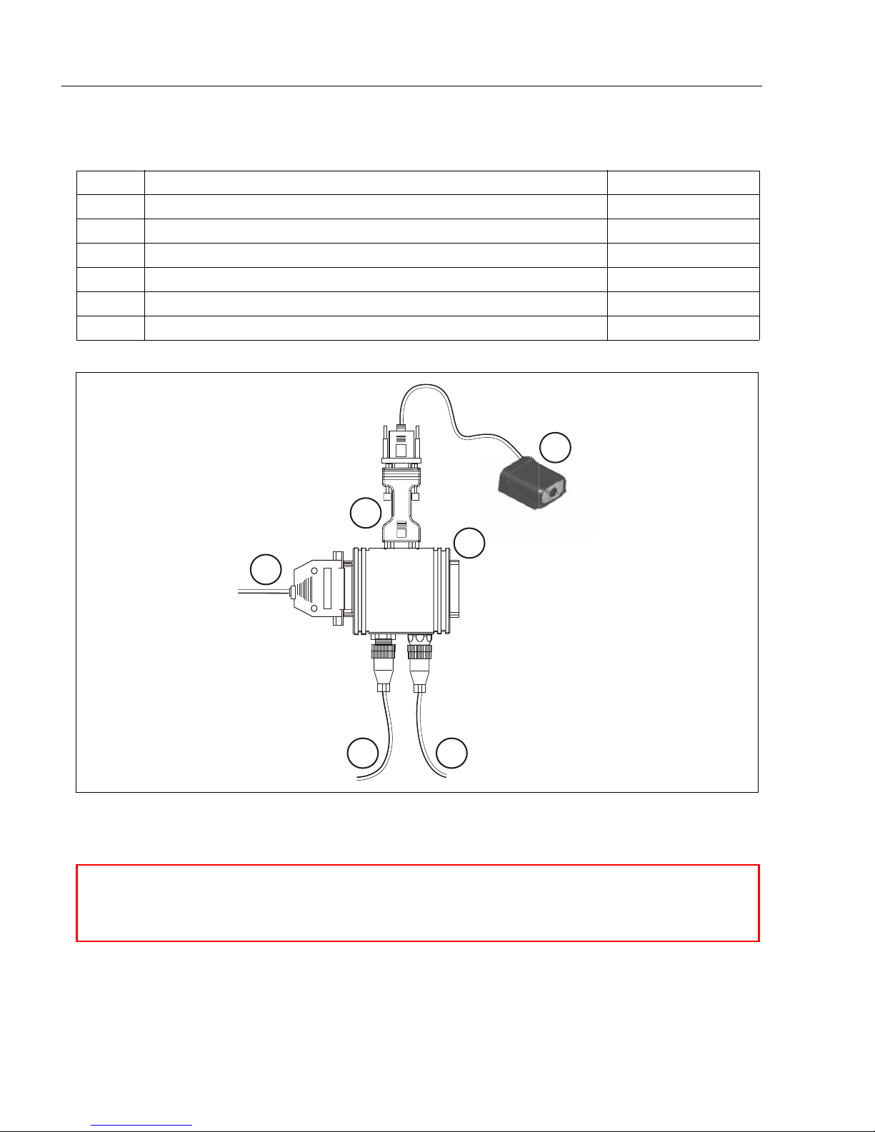
Step 1 — Check Required Hardware
Item Description Part Number
1 Quadrus MINI Imager FIS-6300-XXXXG
2 IC-332 Adapter FIS-0001-0035G
3 IB-131 Interface Box 99-000018-01
4 Power Supply (90-264 VAC, 24VDC, USA/Euro plug) 97-100004-15
5 Object Detector 99-000017-01
6 Communication Cable 61-300026-03
1
2
Scanner
6
Host
3
Network
45
1-2 Quadrus MINI Imager User’s Manual
Page 15
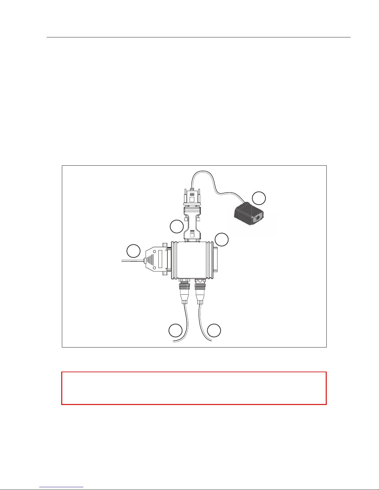
Step 2 — Connect the System
Hardware Configuration
Caution: Be sure that all cables are connected BEFORE applying power
to the system. Always power down BEFORE disconnecting any cables.
Connecting by RS-232/RS-422/RS-485
• Connect the imager (1) to the IB-131/IC-332 interface (2) and (3).
• Connect the host cable (6) to the host and to the host port on the IB-131 (3).
• Connect the object detector (5) to the IB-131 (3).
• Connect the power supply (4) to the IB-131 (3).
• Apply power to the imager.
Quick Start
Important:
before
powering-on. Otherwise the unit will not be recognized as a USB device.
If you are using a
6
USB
model, you must connect the device to the host computer
1
2
Scanner
Host
3
Network
Quadrus MINI Imager User’s Manual 1-3
45
Page 16
Position Imager and Symbol
Imager and Symbol Orientation
Pitch
axis
Bar code
label
Tilt
axis
axis
Scanline
Scanner
Pitch
Tilt
Skew
Symbol
Reader
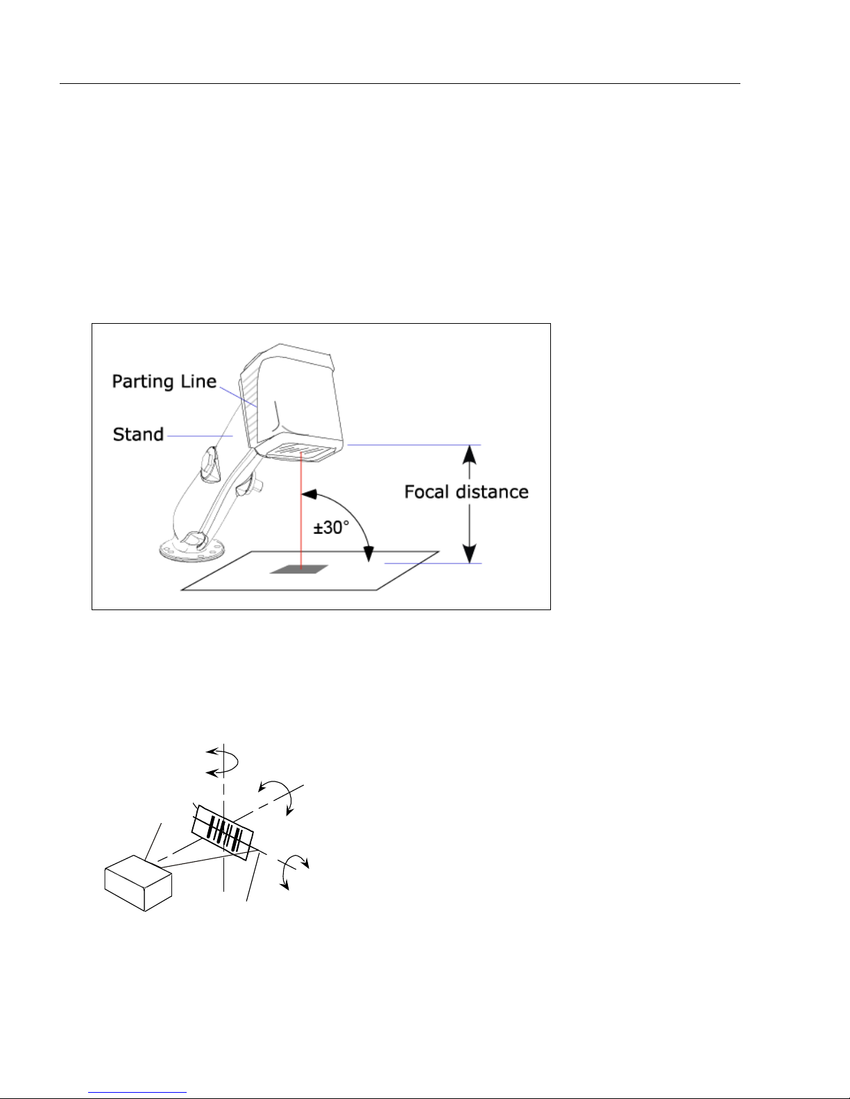
Step 3 — Position Imager and Symbol
• Position the imager at a focal distance between 2 and 6 inches from the symbol.
• Tip the imager relative to the symbol to avoid the glar e of direct (spe cular) reflection. The
case parting line should be perpendicular to the plane of the symbol by either pitching the
symbol or the imager as shown.
• Position the imager in a place with as little ambient light as possible.
• Symbols can be rotated (tilted) at any angle; however, for best results symbols should
be aligned with the FOV (field of view).
• In the case of linear symbols, aligning the bars in the direction of their movement (“ladder”
orientation) will minimize the chances of blurring, and will produce better reads.
Important: Avoid excessive skew or pitch. Maximum skew is ±30°; maximum pit ch is
±30°. The illustration below shows skew axis, pitch axis, and tilt axis.
Note: For accuracy of testing a nd performance, Microscan recommends using a mounting
arm adapter kit. Contact your Mi croscan sales manager for details about mounting arm
adapter kits and other accessories.
1-4 Quadrus MINI Imager User’s Manual
Page 17

Quick Start
Step 4 — Install ESP
Easy Setup Program (ESP) is Microscan’s propriet ar y setup and te sting ap plication. The
purpose of
When the Quadrus MINI is connected to a host computer (Windows Vista, XP, or 2000),
ESP can be used to configure reader settings and to set up communications between the
reader and host.
If installing from the Microscan Tools CD:
1. Insert the Microscan Tools CD in your computer’s CD drive.
2. Select ESP Software from the navigation bar at the left of the screen.
3. Click on ESP Software under the Current Version heading.
4. Click the Run button and follow the prompts in the ESP Setup Wizard.
Note: During installation, you may see an Internet Explorer Security Warning that
states: “The publisher could not be verified.” If you see this warning, click Run to
continue installation.
If downloading from the web:
1. Go to the Download Center at www.microscan.com.
2. Create a new member account or, if you are already a member, enter your user nam e
and password.
3. Navigate to the “Microscan Software” section of the Download Center (near the top of
the page).
4. Click on the link showing the latest version of ESP. Extract the ESP installation files to
a location of your choice on the host computer. Note where your ESP.exe file is stored
on your hard drive.
5. At the end of the installation process, the following icon will appear on your desktop:
ESP
is to provide a quick and easy way to set up and configure Microscan readers.
6. Click the ESP icon to start the program.
System Requirements for ESP
• 166 MHz Pentium processor (recommended)
• Windows Vista, XP, or 2000 operating system
• Internet Explorer 5.0 or higher
• 64 MB minimum RAM
• 40 MB minimum disk space
• 800 x 600 pixel minimum 256 color display
Quadrus MINI Imager User’s Manual 1-5
Page 18
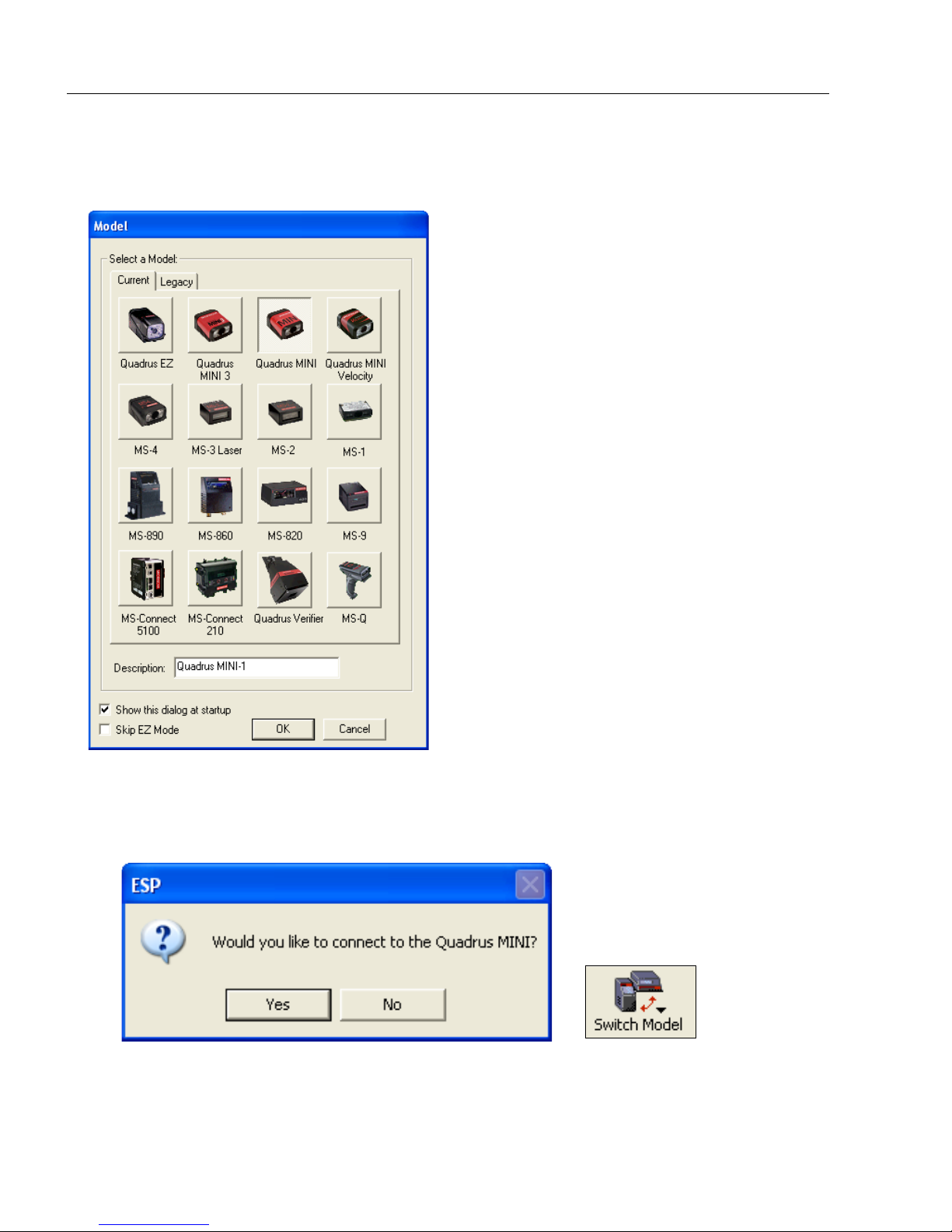
Select Model
Step 5 — Select Model
When you start ESP, the following menu will appear:
1. Click the button showing the Quadrus MINI.
2. Click OK.
Note: You can also double-click the Quadrus MINI button to make your selection.
3. Click Yes when this dialog appears:
Note: If you need to select another model later, click the Switch Model button near
the top of the screen or use Model > New Model in the menu toolbar.
1-6 Quadrus MINI Imager User’s Manual
Page 19
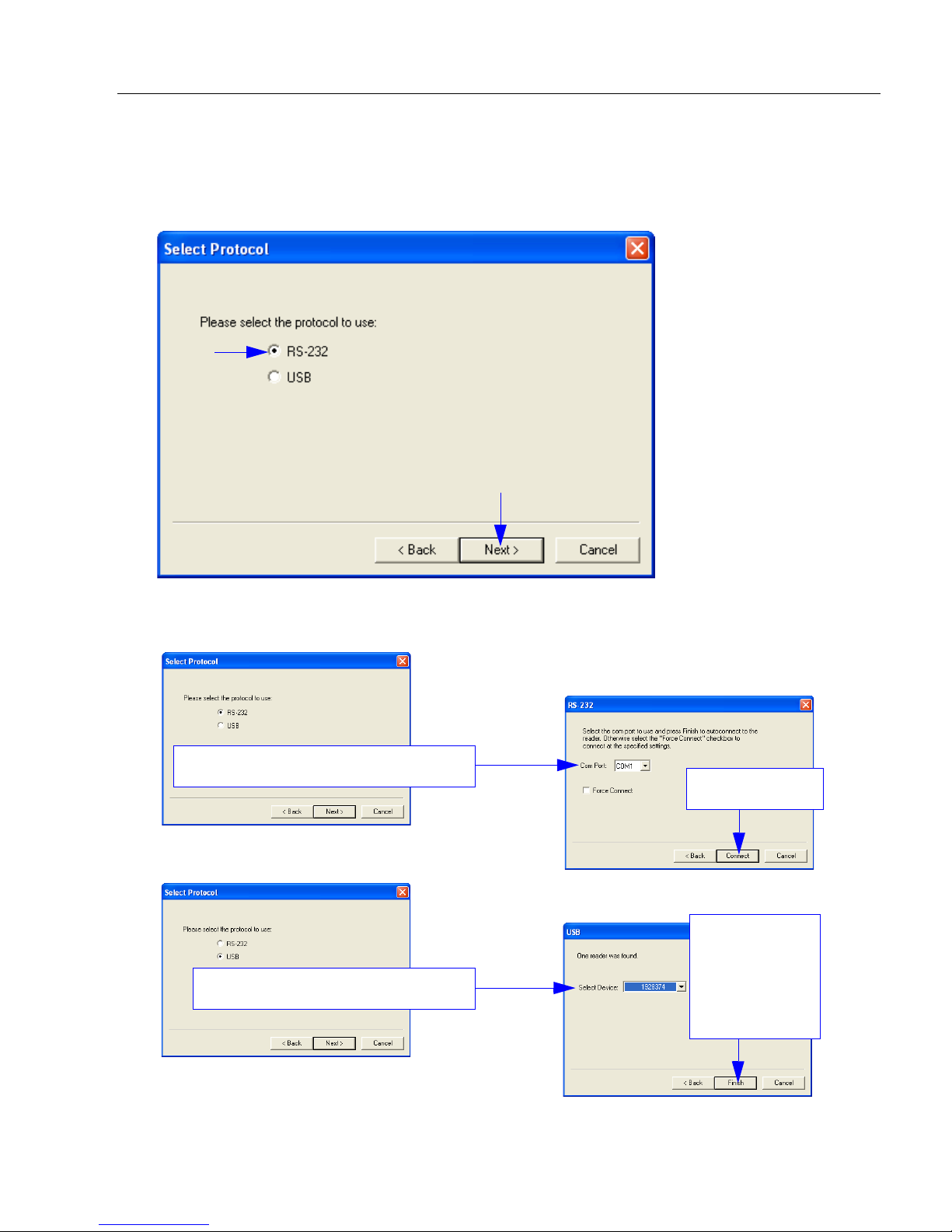
Quick Start
If you choose RS-232 protocol:
Select the
Quadrus MINI
from the
Select Device
menu and click
Finish.
Click Connect.
If you choose USB protocol:
• Once you select your communications mode, follow the prompt s to establish your
connection.
Step 6 — Select Protocol and Connect
• Choose the connection protocol you ar e using and click Next when the Select Protocol
dialog appears.
Quadrus MINI Imager User’s Manual 1-7
Page 20
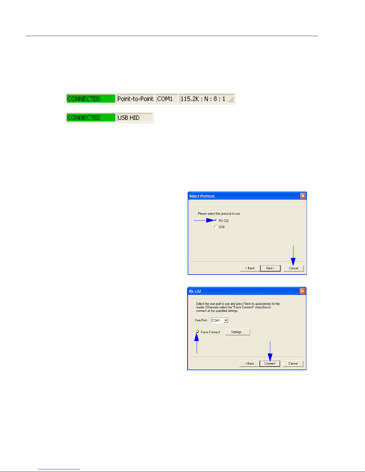
Select Protocol and Connect (cont.)
USB:
RS-232:
Note: If your RS-232 host settings cannot
be changed to match the imager’s settings:
• Click Connect on ESP’ s menu toolbar,
and then select Connection Wizard.
• When the Select Protocol dialog
appears, select RS-232 and click Next.
• When the RS-232 dialog appears,
check the Force Connect box and
click the Connect button.
Step 6 — Select Protocol and Connect (cont.)
When you are connected, you will see the green connection indicator in the status bar at
the bottom right of your screen.
• If your RS-232 connection attempt fails, click the Autoconnect button, select a different
communications port, and try again.
1-8 Quadrus MINI Imager User’s Manual
Page 21
Quick Start
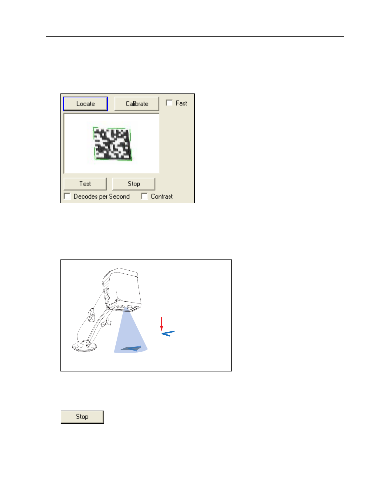
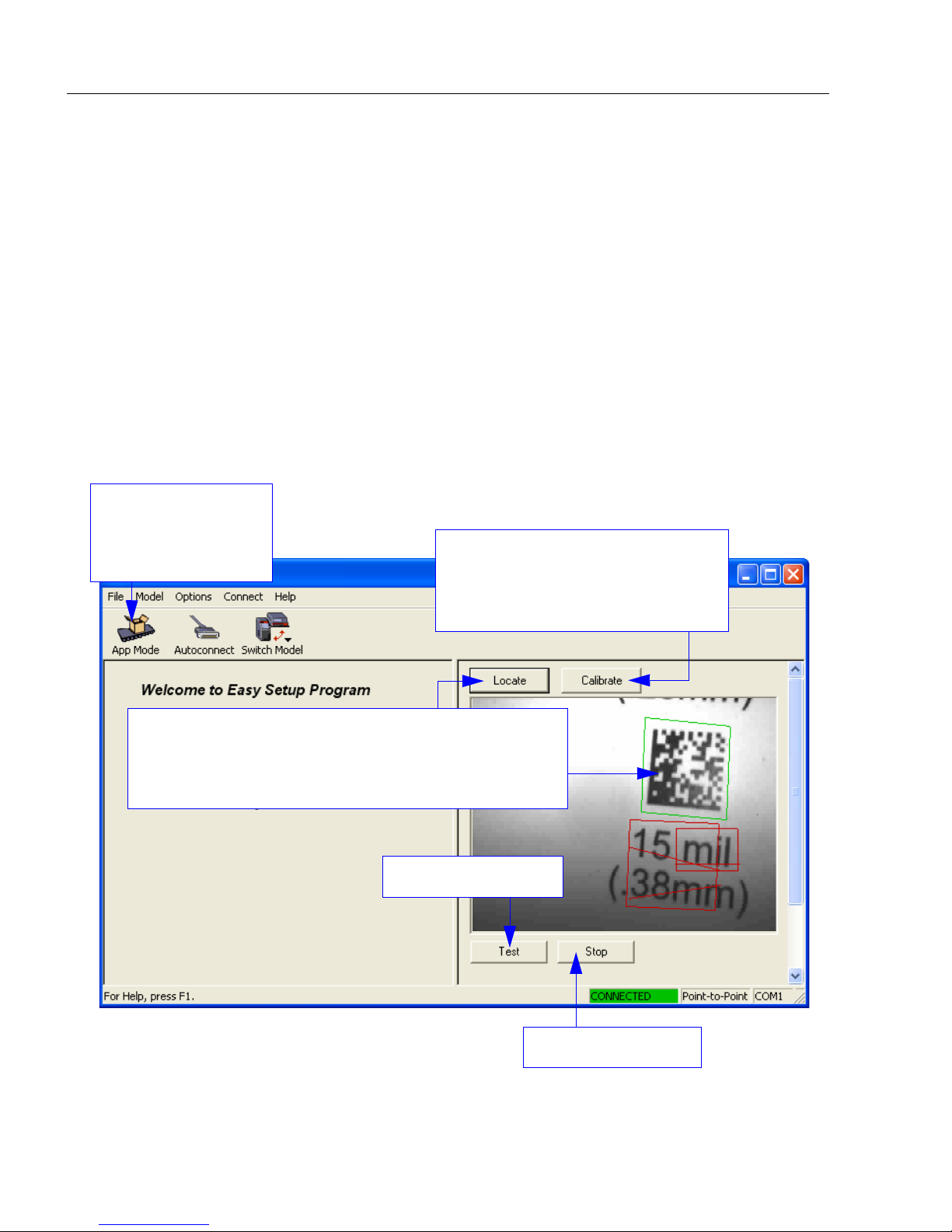
Step 7 —
Locate the Symbol in the Field of View
Locate by ESP
•In ESP’s EZ Mode, click the Locate button to enable the blue target pattern.
The symbol in the field of view will appear in the video vie w beneath th e Locate and
Calibrate buttons, and you will see the blue target pattern projected from the front of the
imager.
• Center the target pattern on the symbol.
At 2 to 3 inches, the pattern resembles an X. At 3 to 6 inches, the pattern resembles a V.
Center on object
in field of view.
Target pattern shown as it would appear between 3 and 6 inches.
Important: The entire symbol should fall within the field of view (FOV) of the imager. The
field of view is what appears in ESP’s Locate/Calibrate window in EZ Mode.
• Click the Stop button to end the Locate function.
Quadrus MINI Imager User’s Manual 1-9
Page 22

Locate the Symbol in the Field of View
EZ Button
Locate by EZ Button
If you are not connected to a host computer, the EZ Button allows you to locate a symbol
in the imager’s field of view.
• Hold down the EZ Button for about one second and release when you hear one short
beep. The amber
from the front of the imager.
• Center the target pattern on the symbol.
Note: To end all EZ Button functions, press the EZ Button once and quickly release.
20%
LED will illuminate, and you will see the blue target pattern projected
1-10 Quadrus MINI Imager User’s Manual
Page 23
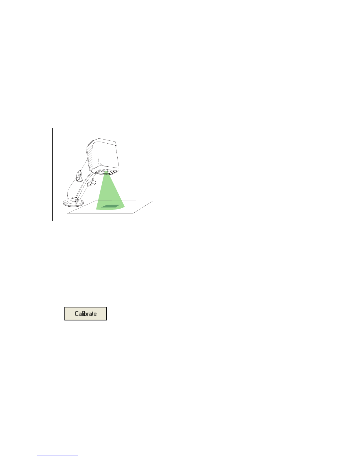
Step 8 — Calibrate
Quick Start
Quadrus MINI settings can be adjusted automatically for optimum symbol decoding performance
by either the EZ Button or by ESP.
During the calibration routine, the reader will flash its amber Read Rate percent LEDs and
red illumination LEDs while searching camera settings and determining the best configuration
for decoding symbol data. Upon succe ssful completion of this routine, a green LED p attern
will flash brightly
and stop searching.
and illuminate the symbol. If unsuccessful, the imager will emit 5 short beeps
Calibrate by EZ Button
1. Hold down the EZ Button for about two seconds and release when you hear two
short beeps. The 20% and 40% LEDs will illuminate.
2. The imager will search camera settings to determine the best configuration for decoding
symbol data.
Note: To end all EZ Button functions, press the EZ Button once and quickly release.
Calibrate by ESP
1. Click the Calibrate button.
2. The imager will search camera settings to determine the best configuration for decoding
symbol data.
A successful calibration will display a green frame around the symbol, and the following
message will appear: “Uploading all reader parameters.” After a moment the symbol
data will be presented in the field below the image display window.
Calibrate by Serial Command
Send <@CAL> from a terminal program to begin calibration.
Quadrus MINI Imager User’s Manual 1-11
Page 24
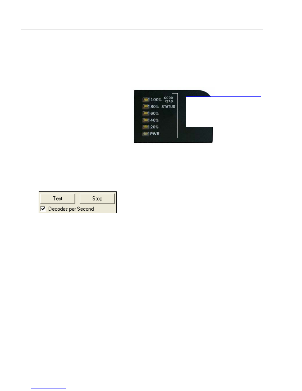
Test Read Rate
20%, 40%, 60%, 80%, 100%.
These LEDs represent the
percentage of Good Reads
per images captured.
Step 9 — Test Read Rate
Read Rate indicates the number of successful decodes per second achieved by the
imager.
Test Read Rate by EZ Button
1. To start the Read Rate test, hold
down the EZ Button about three
seconds until you hear three
short beeps. The 20%, 40%, and
60% LEDs will illuminate.
While the symbol is being
inspected, the Read Rate LEDs
will indicate the corresponding
read rate percentage on the back
of the unit.
2. To end the Read Rate test, press the EZ Button and quickly release.
Test Read Rate by ESP
1. Click the Test button to start the Read Rate test and Stop to end it.
If a symbol has been successfully decoded, the symbol’s data and related features will
be presented in the field below the image display window. Also, while the symbol is
being inspected, the Read Rate LEDs will indicate the corresponding Read Rate
percentage on the back of the unit.
2. To end the test, click the Stop button.
Note: Read Rate can also be tested using the Read Rate interface in Utilities.
Test Read Rate by Serial Command
You can also start a test with the <C> or <Cp> command and end it with the <J> command.
1-12 Quadrus MINI Imager User’s Manual
Page 25
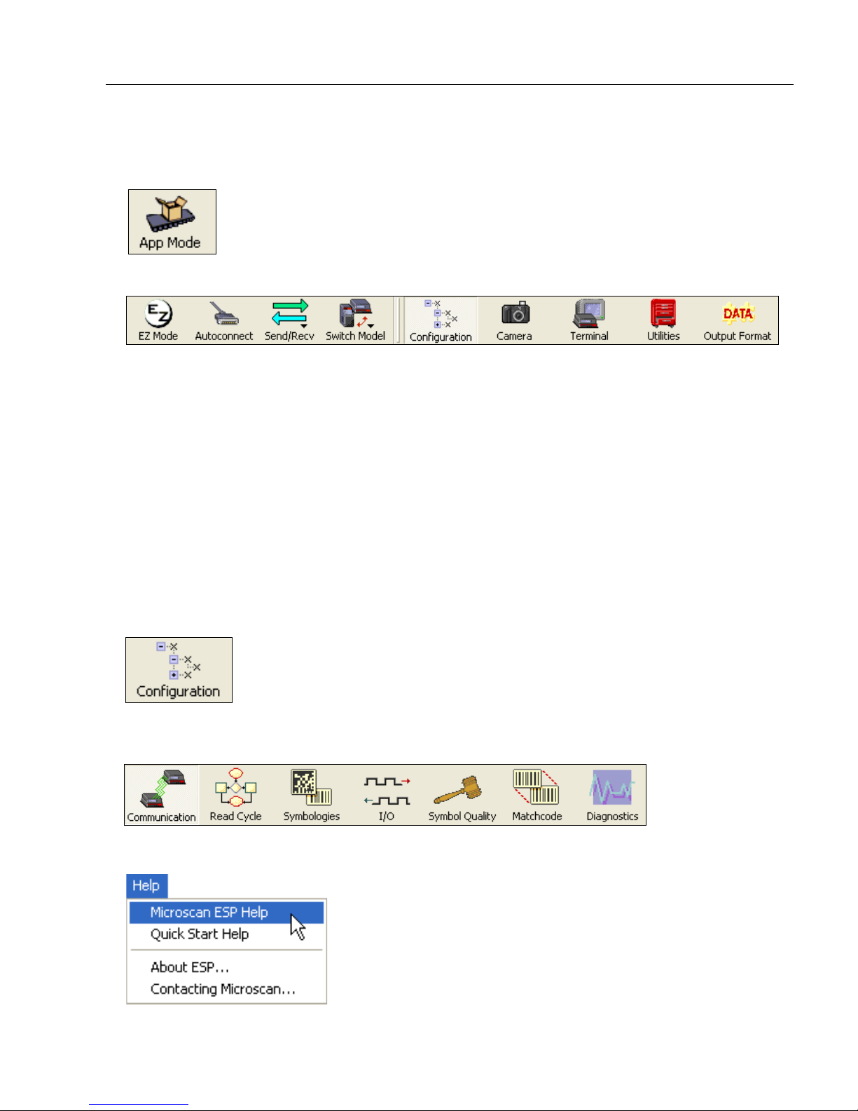
Step 10 — Configur e the Imager in ESP
To make setup changes to Quadrus MINI, click the App Mode button.
Quick Start
The following modes are accessible by clicking the buttons in the first row of
• Click the Autoconnect button to establish communications between ESP and the imager.
• Click the Send/Recv button to send or receive commands.
• Click the Camera button to access a live Video view, Evaluate image captures, Calibrate
the imager, set the Window of Interest, fine-tune capture settings and processing settings
in the Configuration Database, and control multiple read cycle functions in Dynamic Setup.
• Click the Terminal button to display decoded symbol data, and to send serial commands
to the imager using text or macros.
• Click the Utilities button to test Read Rate, request o r clear Counter s, enable or disable
the imager or send output pulses in Device Control, determine the Differences from
Default in the current settings, add or remove master symbol data in Master Database,
and verify or update the imager’s Firmware.
• Click the Output Format button to determine the order and content of data output.
Click the Configuration button to display the second row of ESP icons.
App Mode
icons:
From here you can make changes in the tree controls that can be accessed by clicking the
buttons on the second row of icons in the
For further details, see Microscan ESP Help in the dropdown Help menu.
Quadrus MINI Imager User’s Manual 1-13
ESP
window.
Page 26

Save Configuration in ESP
1. Left-click on the +
to expand the
desired tree.
2. Double-click on the
desired parameter
and click once in the
selection box to view
options.
5. Right-click on the open
screen and select Save to
Reader to implement the
command in the imager.
4. Left-click again on the open
screen to complete your
selection.
3. Place your cursor in the
selection box, scroll down to
the setting you want to
change, and click once on
the setting.
Step 11 — Sav e Configuration in ESP
To make changes to a configuration setting:
Saving Options
• Send, No Save. Changes will be lost when power is re-applied to the imager.
• Send and Save. This activates all changes in current memory and saves to the imager
for power-on.
1-14 Quadrus MINI Imager User’s Manual
Page 27

2 Using ESP
EZ Mode........................ ... ............................ ............................ ............................ .........................2-2
Application Mode...........................................................................................................................2-3
Menu Toolbar................................................................................................................................2-4
Autoconnect................................................................................................................................2-12
View ............................................................................................................................................2-14
Navigating in ESP......................................................... ............................ ......................... .........2-15
Send/Receive Options ................................................................................................................2-16
Using EZ Trax.............................................................................................................................2-18
Contents
This section is designed to help you understand the basic structure and eleme nts of ESP
(Easy Setup Program).
When you open ESP, unless otherwise specified in the ESP Preferences dialog accessible
from the Options heading on the menu toolbar, you will enter EZ Mode for initial setup.
From there, you can enter Application Mode (App Mode) and access several configuration
menus (Communications, Read Cycle, Symbologies, I/O Parameters, Symbol Quality,
Matchcode, and Diagnostics), a Camera setup interface, a Terminal interface, a Utilities
interface, and an Output Format interface.
ESP can be used to configure the Quadrus MINI in three different ways:
•
Tree Controls:
specific element of imager operation. For example, the
Host Port Connections
Bits
, and
• Graphic User Interfaces: Imager settings can be configured using such point-and-click
tools as radio buttons, zoom in/zoom out sliders, spin boxes, check boxes, and drag-and-drop
functions.
• Terminal: ESP’s Terminal allows you to send serial configuration and utility commands
directly to the imager by typing them in the provided text field.
Information about using ESP in specific applications is provided in subsequent sections.
For ESP system requirements, see ESP System Requirement s in Chapter 1, Quick Start.
Each configuration menu contains a list of all option settings that pertain to that
Data Bits
Communications
option, and then a list of the sub-options
. Each of these sub-options is configurable by using dropdown menus.
Baud Rate, Parity, Stop
menu shows a
Quadrus MINI Imager User’s Manual 2-1
Page 28
EZ Mode
Starts Read Rate test.
Click Calibrate to begin the initial
calibration routine. Calbration is
explained at the left of the EZ Mode
screen, and also in Quick Start.
Click Locate to activate the Quadrus MINI’s blue t a rg et
pattern LEDs. Center the target pattern on the symbol.
The display shows you where the symbol is located in
the imager’s field of view.
Ends Read Rate test.
Enter App Mode to
access configuration
trees and other setup
features.
EZ Mode
In
EZ Mode
to your imager ,
instructions that will help you with positioning, testing, and calibration.
Test
Click the Test button to start the Read Rate test for a quick indication of the imager’s read
capabilities and the limits of your application. When Decodes per Second is unchecked,
the test will count the percentage of decodes relative to the number of actual scans. Click
Stop to end the test.
Calibrate
The calibration routine that will optimize the imager by comparing Read Rates at various
camera and image processing set ting s.
you are presented with the
EZ Mode
is the screen you will see. You will be provided with on-screen
Locate, Calibrate
, and
Test
options. After connecting
2-2 Quadrus MINI Imager User’s Manual
Page 29
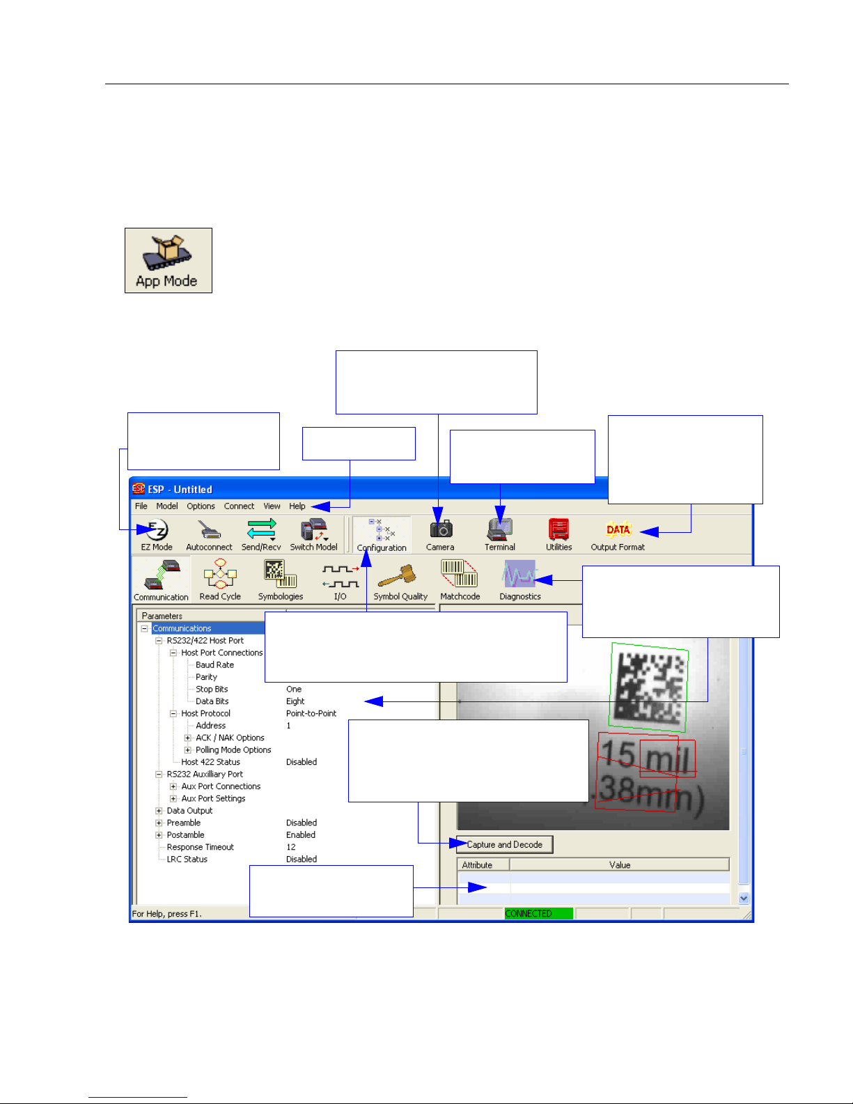
Using ESP
Click here to open
the Terminal view.
Click this icon to
return to EZ Mode.
Menu toolbar.
Camera Setup, advanced
Calibration, Configuration
Database.
Click the Configuration icon to return to full
App Mode view from Camera, Terminal,
Utilities, or Output Format.
Click here for
Ordered Output
and Output Format
features.
Click on icons in this row to
access configuration trees
like the one shown here.
Click Capture and Decode to
read the symbol in the field of
view, and to see a high resolution
image capture of the symbol.
Decoded symbol data
is shown in this table.
Application Mode
From EZ Mode, you can click on the App Mode button to access specific configuration
menus, Utilities tools, Camera setup, Output Format options, and a Terminal window
where serial commands can be entered.
Note: The App Mode and EZ Mode buttons appear in the same position to allow easy
switching between these primary modes.
Note: For specific information on any of the icons shown above in the operations bar or
configuration bar, see the corresponding chapters in this manual.
Quadrus MINI Imager User’s Manual 2-3
Page 30
Menu Toolbar
(Save to Imager)
(Receive Imager
Settings)
Menu Toolbar
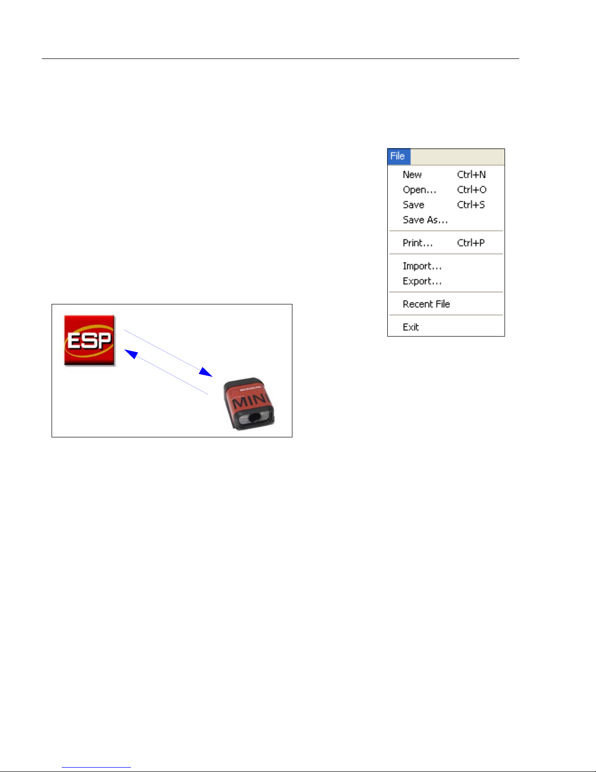
File > New
Whenever New is selected, the default configuration of ESP is
loaded.
Open/Save
When Save or Save As is selected, the ESP configuration is
saved to the host computer’s hard drive and available whenever
the same file is selected under Open.
Important: When you save menu changes to your hard drive,
these changes are not saved to your imager.
below shows how settings can be saved and received between
ESP and the imager, and ESP and the host hard drive.
The illustration
Import/Export
Import converts the ASCII settings from a text file to ESP configuration settings.
Export converts the active ESP configuration settings to an ASCII text file.
2-4 Quadrus MINI Imager User’s Manual
Page 31

Using ESP
Model
In the Model menu you can select any of the models suppo rted by ESP. When you choose
a different model, the connection to your present model will be terminated.
To connect to another model, select New Model, choose a new model from the pop-up
menu that appears, and click OK.
Note: When you save an ESP file, you are saving the settings of all the models defined in
that file.
Quadrus MINI Imager User’s Manual 2-5
Page 32

Menu Toolbar
The Toolbar Style
options allow you to
determine how ESP
will display the mode
options in the two rows
at the top of the screen.
Options
The Options menu allows you to save memos and set up ESP
Preferences.
Note: Preferences will be saved and loaded into ESP whenever ESP
is opened next, whether or not you save the ESP file.
Preferences > General Tab
Reload Last File
At startup, reloads the last file saved to the host computer’s hard drive.
Show Model Prompt
At startup, shows the model menu displaying all supported re aders.
Show Connect Prompt
At startup, displays the Would you like to connect to the Quadrus MINI? prompt.
Receive After Connect
At startup, loads the imager’s settings into ESP. (This is not recommended if you want to
preserve your ESP settings for future use.)
Skip EZ Mode
At startup, skips EZ Mode and opens directly in App Mode.
Enable ‘Send and Save as Customer Defaults’
At startup, enables the Send and Save as Customer Defaults option in the Send/Recv
command.
2-6 Quadrus MINI Imager User’s Manual
Page 33

Using ESP
Preferences > Terminal Tab
Show Non-Printable Characters
When Show Non-Printable Characters is enabled, characters such as “CRLF” will be
displayed in the Terminal window. When Enhanced Format is checked, the characters
are displayed with more detailed formatting.
Change Keyboard Macros
Clicking the Change Keyboard Macros button brings
up the Function Keys dialog. In this dialog you can
select the desired function key and then enter your
macro keystrokes in the associated key map. For
example, to make Ctrl-F2 the keystroke to send a trigger
character, select F2, then in the Ctrl row , enter <trigger
character> and click OK. Then whenever the Ctrl-F2
keystroke is pressed, the trigger character will start the
read cycle.
Note: The F1 key is reserved for opening ESP Help and the F3 key is reserved for the
Find Next function.
Change Font
Allows you to modify the font used for decode data received from the imager on the
screen.
Terminal
Change Echo Font
Allows you to modify the font used for command characters typed into the Terminal view.
Enable Echo
Allows you to enter command characters in Terminal.
Display Incoming Data Even When Not in Focus
When Display Incoming Data Even When Not in Focus is enabled, data from the
imager will continue to appear in the terminal even when ESP is not the top window.
Quadrus MINI Imager User’s Manual 2-7
Page 34

Menu Toolbar
Preferences > Bar Code Options Tab
The Bar Code Options dialog allows you to set the size of user-created symbols.
Sizing Information
Sets the bar width or module width (in
Example: A bar width of 18 is 0.018 inches.
mils
, or thousandths of an inch) of user-created symbols.
2-8 Quadrus MINI Imager User’s Manual
Page 35

Using ESP
Preferences > Advanced Tab
The Auto Sync options at the top of the Advanced tab allow you to determine whether
Auto Sync will be enabled automatically in sections of ESP where it is used, or if it will ask
you before it enables Auto Sync functions.
Always Ask Before Auto Sync Occurs
If you check this option box, you are then able to determine what specific Auto Sync
functi o ns will be enabled. Receive Settings from the Reader will automatically send the
imager’s settings to ESP when Auto Sync is enabled. Send ESP Settings to the Reader
will automatically send all imager configuration settings chosen in ESP to the imager. Do
Not Send or Receive Settings creates a condition in which Auto Sync will not automatically
send imager settings to ESP, or send ESP settings to the imager.
Show Target Pattern During Locate
Allows you to determine whether the blue LED target pattern will be on or off during the
Locate routine.
Show Target Pattern During Calibrate
Allows you to determine whether the blue LED target pattern will be on or off during the
Calibrate routine.
Use Higher Quality Images
Sets ESP to output images at a higher resolution than standard JPEG format.
Open Image after Save
When Open Image after Save is enabled, ESP automatically opens saved image captures.
Images can be saved from the Evaluation tab in the Camera view, or by right clicking an
image in any other image capture view and then saving.
Send XON with Autoconnect
Sends an
routine.
Quadrus MINI Imager User’s Manual 2-9
XON (Begin T rans mission
) command to the imager before starting the
Autoconnect
Page 36

Menu Toolbar
Preferences > Advanced Tab (cont.)
Ask to Save ESP File when Quitting
When enabled, prompts the user to save a .esp file when ending a session.
The .esp file will be saved in the location of your choice.
Connect to Readers via TCP/IP
When enabled, shows a TCP/IP option on the Select Protocol dialog.
Note:
This option should only be selected if you intend to connect using an Ethernet adapter.
Use Default Storage Location
When enabled, automatically stores data in ESP’s Application Data folder.
2-10 Quadrus MINI Imager User’s Manual
Page 37

Using ESP
Document Memo
The information you type in the Document Memo field will appear in a context-sensitive text
box whenever your cursor hovers over the Document Memo item on the Options menu.
Model Memo
Similar to Document Memo, the information you type in the Model Memo field will appear
in a context-sensitive text box whenever your cursor hovers over the Model Memo item on
the Options menu. Memos created in Model Memo are specific to the model enabled
when the message was created.
Note:
Memos must be saved in a
If you do not save your current session, any memos that you have entered during the session
will be discarded, and will be unavailable in your next session.
Quadrus MINI Imager User’s Manual 2-11
.esp
file if you want them to available in your next session.
Page 38

Autoconnect
• Once you have
chosen the correct
port, click Start to
connect.
Autoconnect
•
If your RS-232 connection attempt fails, you can use
between the imager and the host.
• If your communications port is not the default COM1, use the dropdown menu to change
your port.
Autoconnect
to establish a connection
When you are connected, you will see the green connection indicator in the status bar at
the bottom right of your screen:
Important: If you are using a USB model, you must connect the device to the host
computer before powering-on. Otherwise the unit will not be recognized as a USB
device.
2-12 Quadrus MINI Imager User’s Manual
Page 39

Autoconnect (cont.)
• Click Connect on ESP’ s menu toolbar,
and then select Connection Wizard.
• When the Select Protocol dialog
appears, select RS-232 and click Next.
• When the RS-232 dialog appears,
check the Force Connect box and
click the Connect button.
If your RS-232 host settings cannot be changed to match the imager’s settings:
Using ESP
Quadrus MINI Imager User’s Manual 2-13
Page 40

View
Drag specific configuration
values from the control tree
directly into this field to
encode new symbols.
Choose a spatial
orientation for the
new symbol.
The symbol you create
will be displayed in the
field at the bottom of the
Bar Code Dialog.
Create a caption
for the symbol
that matches the
encoded data, or
write your own
caption.
View
The View menu allows you to move quickly between interfaces
without using the icon buttons on the App Mode toolbar. It also
allows you to access the Bar Code Dialog.
Bar Code Dialog
In the
Bar Code Dialog
you can create symbols by typing the text you
wish to encode. This is a useful tool for crea ting confi gurat ion symbo ls,
allowing you to configure your reader by reading the symbols you create.
2-14 Quadrus MINI Imager User’s Manual
Page 41

Using ESP
1. Left click on the + to
expand menu items.
2. Double-click the
desired parameter and
single-click in the
selection box to view
options.
3. Place your cursor in the
selection box, scroll
down to the setting you
want to change, and
single-click the setting.
4. Left click again on the open screen to complete the
selection.
5. Right click on the open screen and select Save to
Reader to implement the command in the imager.
You can send the command without saving it, or you
can send and save the command simultaneously.
The X denotes the
default option setting.
Navigating in ESP
To change imager settings, or to access the Utilities, Camera, Terminal, or Output Format
views, click the App Mode button.
To return to EZ Mode, click the EZ Mode button.
To make changes to configuration settings in the control trees:
Quadrus MINI Imager User’s Manual 2-15
Page 42

Send/Receive Options
Send/Receive Options
To access Receive, Save, and Default options, click the Send/Recv button. You can also
access these options by right-clicking in any of the configuration views.
Receiving
From the Send/Recv menu, select Receive Reader Settings.
Caution: Do not select this option if you do not want to upload the imager’s settings. For
example, if your ESP file has a number of custom settings that you want to maintain and
download into the imager, these settings would be lost by choosing Yes.
This is useful if you want to receive (upload) the imager’s settings and save them as a file
for future use. For example, if your imager has settings that you do not want to change,
choosing Yes would allow you to load those settings to ESP and save them in an ESP file
for later retrieval.
Receiving the imager’s settings will also assure that you will not be subsequently saving
any unwanted changes that you or someone else has made previously in ESP.
Saving
Send, No Save (<A>)
Saves
memory.
Send and Save (<Z>)
Activates all changes in
current memory and saves
to the imager for power-on.
Send and Save as Customer Defaults (<Zc>)
Saves your default settings for quick retrieval.
This option will be visible only if you have checked Enable ‘Send and Save as Customer
Defaults’ in ESP Preferences.
ESP
settings to current
2-16 Quadrus MINI Imager User’s Manual
Page 43

Using ESP
Defaulting
When you select Default Current Menu Settings or Default all ESP Settings, you are
only defaulting the ESP settings.
Advanced Options
Send Current View
This is the same as
>
Send No Save
commands in the current configuration
tree are sent.
Save to Reader
except that only the
Send Current Command
This is the same as
View
, except that it saves only the
command that is currently selected.
Send Current
Add/Remove Exception
After you perform a
option, you may see a list of serial commands. These are commands that may be in your
imager’s firmware, but not included in, or different from, your current version of
You can edit these commands by double-clicking on them and changing them as needed.
It is important to note that these commands will be saved to your imager whenever you
send a Save to Reader command, or an <A> or a <Z> command.
Also, if there is a corresponding ESP menu item, the ESP Value column for that item will
be blank following a Receive Reader Settings command.
Receive Reader Settings
command1 and you click on the
Add Exception
ESP
.
1. From the Send/Recv button or by right-clicking in any b l a nk sect ion o f a tree co ntrol view.
Quadrus MINI Imager User’s Manual 2-17
Page 44

Using EZ Trax
Using EZ Trax
For detailed information about using EZ Trax, refer to the Help menu in EZ Trax software,
or the EZ Trax Quick Start Guide, available on the Microscan Tools CD.
For information about how to configure the Quadrus MINI for use with EZ Trax, see Setting
Up the Imager for EZ Trax in Chapter 5, Read Cycle.
2-18 Quadrus MINI Imager User’s Manual
Page 45

Contents
Communications by ESP..............................................................................................................3-2
Communications Serial Commands..............................................................................................3-3
Host Port Connections...................................................... ... .. .......................................................3-4
Host Port Protocol.................................................... .....................................................................3-5
ACK/NAK Options.........................................................................................................................3-7
Polling Mode Options....................................................................................................................3-8
RS-422 Status...............................................................................................................................3-9
Auxiliary Port Connections........................................................ ... ...............................................3-10
Auxiliary Port System Data Status..............................................................................................3-18
Daisy Chain Autoconfigure .........................................................................................................3-19
Response Timeout......................................................................................................................3-20
LRC Status..................................................................................................................................3-21
Protocol Configuration Examples................................................................................................3-22
USB HID Interface ...................................................... ............................ ....................................3-23
ASCII Character Entry Modifier...................................................................................................3-32
Preamble.....................................................................................................................................3-33
Postamble...................................................................................................................................3-34
3 Communications
This section explains how to set up communications parameters with the host and an
auxiliary termina l.
With Microscan’s ESP (Easy Setup Program), configuration changes can be made in the
ESP
menus and then sent and saved to the imager. The user can also send serial commands
to the imager via ESP’s Terminal window.
Quadrus MINI Imager User’s Manual 3-1
Page 46

Communications by ESP
Click this button
to bring up the
App Mode view.
Click this button
to bring up the
Communication
tree control.
To open nested options,
single-click the +.
T o change a setting, double-click the
setting and use your cursor to scroll
through the options.
Communications by ESP
3-2 Quadrus MINI Imager User’s Manual
Page 47

Communications
Communications Serial Commands
Host Port Connections <K100,baud rate,parity,stop bits,data bits>
Auxiliary Port Connections <K101,aux port mode,baud rate,parity,stop bits,data
bits,daisy chain ID status,daisy chain ID>
RS-422 Status <K102,status>
Host Port Protocol <K140,protocol,address>
Preamble <K141,status,preamble characters>
Postamble <K142,status,postamble characters>
Response Timeout <K143,response timeout>
LRC <K145,status>
Auxiliary Port System Data Status <K146,aux port system data status>
ACK/NAK Options <K147,RES,REQ,STX,ETX,ACK,NAK>
Polling Mode Options <K148,RES,REQ,STX,ETX,ACK,NAK>
Autoconfiguration Daisy Chain <K150DAISY>
Quadrus MINI Imager User’s Manual 3-3
Page 48

Host Port Connections
Host Port Connections
The host port can be configured with RS-232, RS-422, and RS-485 connections.
The following settings define the basic transmission speeds and digital standards that
ensure common formatting.
Baud Rate, Host Port
Usage: Can be used to transfer data faster or to match host port settings.
Definition: The rate at which the reader and host transfer data back and forth.
Serial Cmd: <K100,baud rate,parity,stop bits,data bits>
Default: 115.2K
Options: 0 = 600 1 = 1200 2 = 2400
3 = 4800 4 = 9600 5 = 19.2K
6 = 38.4K 7 = 57.6K 8 = 115.2K
9 = 230K
Parity, Host Port
Usage: Only changed if necessary to match host setting.
Definition: An error detection routine in which one dat a bit per character is se t to 1 or 0
so that the total number of bits in the data field is either even or odd.
Serial Cmd: <K100,baud rate,parity,stop bits,data bits>
Default: None
Options: 0 = None 1 = Even 2 = Odd
Stop Bits, Host Port
Usage: Only changed if necessary to match host setting.
Definition: One or two bits added to the end of each character to indicate th e end of
the character.
Serial Cmd: <K100,baud rate,parity,stop bits,data bits>
Default: One
Options: 0 = One 1 = Two
Data Bits, Host Port
Usage: Only changed if necessary to match host setting.
Definition: One or two bits added to the end of each character to indicate th e end of
the character.
Serial Cmd: <K100,baud rate,parity,stop bits,data bits>
Default: Eight
Options: 0 = Seven 1 = Eight
Note: See USB HID Interface on page 3-23 for protocol information relating to USB.
3-4 Quadrus MINI Imager User’s Manual
Page 49

Communications
Host Port Protocol
Usage: In general, the point-to-point protocols will work well in most applications.
They require no address and must us e RS-232 or RS- 422 communications
standards.
Definition: Protocols define the sequence and format in which information is transferred
between the reader and the host, or in the case of Multidrop, between the
readers and a concentrator.
Serial Cmd: <K140,protocol,address>
Default: Point-to-Point
Options: 0 = Point-to-Point
1 = Point-to-Point with RTS/CTS
2 = Point-to-Point with XON/XOFF
3 = Point-to-Point with RTS/CTS and XON/XOFF
4 = ACK/NAK
5 = Polling Mode
Note: In all protocol modes, the preamble <K141> and postamble <K142> character
strings can be used to frame the decode data, and both are included in calculating the
LRC (Longitudinal Redundancy Check).
Point-to-Point (Standard)
Usage: Used only with RS-232 or RS-422.
Definition: St andard Point-to-Point requires no address and sends the data to the
host whenever it is available, without a request or handshake from the host.
Serial Cmd: <K140,0>
Point-to-Point with RTS/CTS
Usage: A reader initiates a data transfer with an RTS (request-to-send) transmission.
The host, when ready, responds with a CTS (clear-to-send) and the data is
transmitted. RTS and CTS signals are transmitted over two dedicated wires
as defined in the RS-232 standar d. Used only with RS-232.
Definition: Point-to-Point with RTS/CTS (request-to-send/clear-to-send) is a simple
hardware handshake protocol that allows a reader to initiate data transfers
to the host.
Serial Cmd: <K140,1>
Point-to-Point with XON/XOFF
Usage: If an XOFF has been received from the host, data will not be sent to the host
until the host sends an XON. During the XOFF phase, the host is free to carry
on other chores and accept data from other devices. Used only with RS-232.
Definition: This option enables the host to send the XON and XOFF command as a
single byte transmission command of start (^Q) or stop (^S).
Serial Cmd: <K140,2>
Quadrus MINI Imager User’s Manual 3-5
Page 50

Host Port Protocol
Point-to-Point with RTS/CTS and XON/XOFF
Usage: Used only with RS-232.
Definition: This option is a combination of Point-to-Point with RTS/CTS and Point-
to-Point with XON/XOFF.
Serial Cmd: <K140,3>
ACK/NAK
Definition: See the ACK/NAK Options command <K147> on page 3-7.
Serial Cmd: <K140,4>
Polling Mode
Definition: See the Polling Mode Options command <K148> on page 3-8.
Serial Cmd: <K140,5>
Poll Address
Serial Cmd: <K140,protocol,address>
Default: 1
Options: 1 to 50
1 = Poll address 0x1C, Select address 0x1D
2 = Poll address 0x1E, Select address 0x1F
...
50 = Poll address 0x7E, Select address 0x7F
Note: See USB HID Interface on page 3-23 for protocol information relating to USB.
3-6 Quadrus MINI Imager User’s Manual
Page 51

ACK/NAK Options
Communications
Definition:
Serial Cmd: <K147,RES,REQ,STX,ETX,ACK,NAK>
These parameters take effect for
RS-422 ports (not on the Auxiliary Port), and are completely independent of
the
Polling Mode Options <K148>
The imager always follows the protocol in both directions (to and from the
host). There is no option to disable it from either direction.
ACK/NAK <K140,4>
.
on the main RS-232 or
RES-NAK Defaults
RES: (Reset) 00 (disabled)
REQ: (Request) 00 (disabled)
STX: (Start of Text) 00 (disabled)
ETX: (End of Text) 00 (disabled)
ACK: (Acknowledge) 06
NAK: (Negative Acknowledge) 15
The following are general outlines of the ACK/NAK protocol. Items that are framed by
brackets ( [ ] ) can either be disabled or enabled. LRC does not include STX, but it does
include preamble, postamble, and ETX.
Symbol Data Output
TX to host: [STX] [preamble] SYMBOL DATA [postamble] [ETX] [LRC]
Response from host: ACK/NAK. Sent when LRC, ETX, postamble, or timeout (waiting
for more data) are detected (if REQ is disabled) depending on what is enabled.
Commands from Host to Imager
TX to Imager: [STX] <command> [ETX] [LRC]
Response from Imager: ACK/NAK. Sent when LRC, ETX, or command-ending angle
bracket ‘>’ are received, depending on what is enabled.
Command Response from Imager to Host
TX to host: [STX] [preamble] COMMAND RESPONSE DATA [postamble] [ETX] [LRC]
Response from host: ACK/NAK. Sent when LRC, ETX, postamble, command-ending
angle bracket ‘>’, or timeout (waiting for more data) are detected, depending on what is
enabled.
As with Polling Mode <K140,5>, the imager can optionally perform the REQ and RES
event sequences in ACK/NAK mode. If the sender does not receive an ACK or NAK, it will
send REQ to request such a response (if enabled). When the sender receives an ACK, too
many NAKs, or times out (if already enabled), it will send a RES (if enabled) to terminate the
transaction.
Note:
See
ACK/NAK Data Flow Examples
scenarios.
Note: See USB HID Interface on page 3-23 for protocol information relating to USB.
in Appendix E for sample ACK/NAK communication
Quadrus MINI Imager User’s Manual 3-7
Page 52

Polling Mode Options
Polling Mode Options
Definition: These parameters only take ef fect for Polling Mode <K140,5> on the main
RS-232 or RS-422 ports (not on the Auxiliary Port), and are completely
independent of the ACK/NAK Options <K147>.
The values of protocol character s can be changed, but the protocol events
cannot be disabled. The polling mode address is configured in the <K140>
command (see Poll Address on page 3-6).
To enable true multidrop protocol, the RS422/485 port must be enabled,
<K102,1>, in order to turn the transmitter on and off. If RS-232 is enabled
instead of RS422/485, <K102,0>, then Polling Mode will operate as a
Point-to-Point polling protocol. This is because the RS-232 transmitter is
always left on when enabled.
Serial Cmd: <K148,RES,REQ,STX,ETX,ACK,NAK>
RES-NAK Defaults
RES: (Reset) 04
REQ: (Request) 05
STX: (Start of Text) 02
ETX: (End of Text) 03
ACK: (Acknowledge) 06
NAK: (Negative Acknowledge) 15
Note: See Polling Mode Data Flow Examples in Appendix E for sample Polling Mode
communication scenarios.
Note: See USB HID Interface on page 3-23 for protocol information relating to USB.
3-8 Quadrus MINI Imager User’s Manual
Page 53

Communications
RS-422 Status
Usage: RS-232 is an industry standard. RS- 422 is used when greater cable le ngths
are required and/or where noise interference is an issue.
Definition: RS-422, if enabled, allows communication through RS-422 I/O lines.
When RS-422 is enabled, RS-232 is disabled.
When RS-422 is disabled, RS-232 is enabled.
Serial Cmd: <K102,status>
Default: Disabled
Options: 0 = Disabled 1 = Enabled
Note: The default setting can only be changed in readers with multiplexed RS-232/RS-422
ports. It is forced to 1 (enabled) in readers with “d edicated” RS-422 por ts.
Quadrus MINI Imager User’s Manual 3-9
Page 54

Auxiliary Port Connections
Auxiliary Port Connections
The auxiliary port offers an alternative port that can be configured to commun icate by
RS-232 in several modes, including daisy chain.
As with the host port parameters, the auxiliary port settings (baud rate, parity, stop bits,
and data bits) must be identical with those of the auxiliary device.
Usage: An auxiliary port connects the imager to a remote display or to other readers
that can display or transfer data.
Definition: These commands set the communication parameters with the auxiliary
port, which can be used to configure menus, send data to the host, display
data transmissions originating from the host, and relay data from other
imagers set in tandem (daisy chained).
Auxiliary Port Mode
Usage: Can be used to transfer data faster or to match an auxiliary device.
Definition: Determines the flow of data between the auxiliary port device(s), the
imager, and the host..
Serial Cmd: <K101,aux port mode,baud rate,parity,stop bits,data bits,daisy chain i.d.
status, daisy chain i.d.>
Default: Disabled
Options: 0 = Disabled 1 = Transparent 2 = Half duplex
3 = Full duplex 4 = Daisy chain
5 = Command Processing
Baud Rate, Auxiliary Port
Usage: Can be used to transfer data faster or to match an auxiliary device.
Definition: The rate at which the imager and host transfer data back and forth.
Serial Cmd: <K101,aux port mode,baud rate,parity,stop bits,data bits,daisy chain i.d.
status,daisy chain i.d.>
Default: 115.2K
Options: 0 = 600 1 = 1200 2 = 2400
3 = 4800 4 = 9600 5 = 19.2K
6 = 38.4K 7 = 57.6K 8 = 115.2K
9 = 230K
3-10 Quadrus MINI Imager User’s Manual
Page 55

Communications
Parity, Auxiliary Port
Usage: Only changed if necessary to match host setting.
Definition: An error detection routine in which one data bit in each cha racter is set to 1
or 0 so that the total number of 1 bits in the data field is even or odd.
Serial Cmd: <K101,aux port mode,baud rate,parity,stop bits,data bits,daisy chain i.d.
status,daisy chain i.d.>
Default: None
Options: 0 = None 1 = Even 2 = Odd
Stop Bits, Auxiliary Port
Usage: Only changed if necessary to match host setting.
Definition: Allows the user to select the last one or two bits in each character to indicate
the end of the character.
Serial Cmd: <K101,aux port mode,baud rate,parity,stop bits,data bits,daisy chain i.d.
status,daisy chain i.d.>
Default: One
Options: 0 = One 1 = Two
Data Bits, Auxiliary Port
Usage: Only changed if necessary to match host setting.
Definition: Number of bits in each character.
Serial Cmd: <K101,aux port mode,baud rate,parity,stop bits,data bits,daisy chain i.d.
status,daisy chain i.d.>
Default: Eight
Options: 0 = Seven 1 = Eight
Quadrus MINI Imager User’s Manual 3-11
Page 56

Auxiliary Port Connections
Host
Aux.
Port
Imager
Host
Aux.
Port
Imager
Host
Aux.
Port
Imager
Transparent Mode
Usage: A common application, in conjunction with handheld imagers, is one that
employs an auxiliary readout to detect misapplied symbols.
Definition: In Transparent Mode, data is passed between the auxiliary port and the
host. The imager buffers data from the auxiliary port and echoes the keyed
data on the auxiliary port.
• Auxiliary port data is passed through to the
host whenever a return key is pressed at the
auxiliary port or whenever symbol data is
sent. If sent with symbol data, it is processed
on a first-in/first-out basis.
• Auxiliary port data to the host is always sent
with a preamble and postamble.
• If the imager is in a polling mode with the
host, auxiliary port data will still pass
through.
Data Originating from the Imager
• Transmission to the auxiliary port occurs
immediately upon a good read.
• Data sent to the auxiliary port does not include
a preamble or a postamble.
• Communications with the auxiliary port is
always in Point-to-Point protocol, even if the
host is in a polled protocol mode.
Data Originating from the Host
• All host data is echoed to the auxiliary port in
unpolled mode.
Serial Cmd: <K101,aux port mode,baud rate,parity,stop bits,data bits,daisy chain i.d.
Options: 1 = Transparent
3-12 Quadrus MINI Imager User’s Manual
status,daisy chain i.d.>
Page 57

Communications
Host
Aux.
Port
Imager
Host
Aux.
Port
Imager
Host
Aux.
Port
Imager
Half Duplex Mode
Usage: Useful when the user wants symbol data displayed on an auxiliary menu
close to the imager.
Definition: In Half Duplex Mode all auxiliary port dat a and symbol data is sent directly
to the host. Symbol data is displayed on the auxiliary port menu at the
same time the data is sent to the host.
Data Originating from the Auxiliary Port
• Auxiliary port data to the host is ignored if the
imager is in a polled mode.
• Auxiliary port data or read data is sent to the
host whenever it is received.
• Auxiliary port data is not echoed.
• Auxiliary port data to the host is always sent
without a preamble or postamble.
Data Originating from the Imager
• Data is transmitted to the auxiliary port at the
same time it is transmitted to the host.
• Data transmission conforms with all p arameters
specified in the configuration menu (e.g. Preamble
Postamble, End of Read Cycle).
,
Data Originating from the Host
• All host data is echoed to the auxiliary port in
unpolled mode.
Serial Cmd. <K101,aux port mode,baud rate,parity,stop bits,data bits,daisy chain i.d.
status,daisy chain i.d.>
Options: 2 = Half Duplex
Quadrus MINI Imager User’s Manual 3-13
Page 58

Auxiliary Port Connections
Host
Aux.
Port
Imager
Host
Aux.
Port
Imager
Host
Aux.
Port
Imager
Full Duplex Mode
Usage: When communication to and from the auxiliary port is required.
Definition: In Full Duplex Mode all auxiliary port data and symbol dat a is sent directly
to the host. Symbol data is not displayed on the auxiliary port menu.
Data Originating from the Auxiliary Port
• Auxiliary port data to the host is ignored if the
imager is in a polled mode.
• Auxiliary port data or read data is sent to the
host whenever it is received.
• Auxiliary port data is not echoed.
•
Auxiliary port data to the host is always sent
without
Data Originating from the Imager
• Data is not sent to the auxiliary port.
a preamble or postamble.
Data Originating from the Host
• All host data is echoed to the auxiliary port in
unpolled mode.
Serial Cmd: <K101,aux port mode,baud rate,parity,stop bits,data bits,daisy chain i.d.
status,daisy chain i.d.>
Options: 3 = Full Duplex
3-14 Quadrus MINI Imager User’s Manual
Page 59

Communications
Daisy Chain Mode
Usage: Useful in applications where:
• More than one symbol type is present.
• A symbol may be present on multiple sides of a package.
• Symbols are presented at different depths.
Definition: In a daisy chain application, readers are connected in tandem or a “daisy
chain” and decoded data is relayed from one reader to another until the
data reaches the host.
A primary reader has its host port linked to the host computer and its auxiliary
port linked to the host port of the first secondary reader in the chain.
Thereafter, each secondary reader’s auxiliary port is linked to the host port
of the secondary reader that is farther from the host in the daisy chain.
Each reader in the chain can be assigned an ID that accomp anies any data
that it sends.
Serial Cmd: <K101,aux port mode,baud rate,parity,stop bits,data bits,daisy chain i.d.
status,daisy chain i.d.>
Options: 4 = Daisy Chain
Function: Before the primary reader times out, it checks its auxiliary port for data. It
should be set to wait at least 30 ms for each secondary reader in the daisy
chain. If no data is received within the read cycle timeout, the primary
reader sends a No Read message to th e host. Otherwise the complete dat a
is sent.
If, for example, the primary reader is set to timeout in 120 ms, the first
secondary reader reader downstream might be set to 90 ms, the next to 30
ms, and so forth, thus assuring that at least 30 ms el apses between transmissions.
Daisy-chained readers can send a series of symbols by enabling
and a common multisymbol separator. If the primary reader does not
receive the expected number of symb o ls, No Re ad me ssage s ar e
appended to the dat a string to make up the dif f erence between the n umber
of symbols enabled in Multisymbol and the number of symbols read.
For example, a primary and two secondary readers have Number of
Symbols set to 3 and Multisymbol Separator defined as %. If the primary
and the first secondary reader do not find symbols, but the next secondary
reader registers a good read, the transmitted results would be:
symbol data % No Read % No Read
Multisymbol
a
a. The above example assumes a best-case scenario. Other factors, such as baud rate, dynamic focus
timing, number of characters in a given symbol, and the number of secondary readers in the daisy chain
can affect timing and may need to be included in your calculations for complete accuracy.
Quadrus MINI Imager User’s Manual 3-15
Page 60

Auxiliary Port Connections
Command Processing Mode
Usage: Allows a user to send configuration settings from the host port to the auxiliary
port.
Definition: When enabled, Command Processing Mode allows commands to be
entered via the auxiliary port and direct externally triggered read cycle data
in one of two ways:
• Symbol data, including the serial trigger (if used), will be transmitted to
the last port from which a command was sent.
• If the last command came from the host port, then externally triggered
read cycle data will only be output to the host port.
Serial Cmd: <K101,aux port mode,baud rate,parity,stop bits,data bits,daisy chain i.d.
status,daisy chain i.d.>
Options: 5 = Command Processing
3-16 Quadrus MINI Imager User’s Manual
Page 61

Communications
Daisy Chain ID Status
Usage: Used in a daisy chain setup in cases where the host needs to know which
reader in the chain sent the data.
Definition: Each reader in a daisy chain can be assigned a one or two character ID
that will appear in front of decoded data and identify its source.
Serial Cmd: <K101,aux port mode,baud rate,parity,stop bits,data bits,daisy chain i.d.
status, daisy chain i.d.>
Default: Disabled
Options: 0 = Disabled 1 = Enabled
Note: Enable/disable and length must be the same in all readers.
Daisy Chain ID
Usage: Used in a daisy chain setup in cases where the host needs to know which
reader in the chain sent the data.
Definition:
Serial Cmd:
Default: 1/
Options: Any one or two ASCII characters.
A one or two character prefix which identifies the particular daisy chain
reader from which the data is being sent to the host.
<K101,aux port mode,baud rate,parity,stop bits,data bits,daisy chain i.d.
status,daisy chain i.d.>
Important:
For <: <K101h,,,,,,,3C>
For >: <K101h,,,,,,,3E>
, : <K101h,,,,,,,2C>
For
See ASCII Character Entry Modifier on page 3-32 for a detailed explanation of how to
enter ASCII characters as hex values.
The ASCII characters <, >, and , can only be entered as hex pairs:
Quadrus MINI Imager User’s Manual 3-17
Page 62

Auxiliary Port System Data Status
Auxiliary Port System Data Status
Definition: When enabled, system data will be routed to the Auxiliary Port. This
includes decoded data and diagnostic warning messages.
When disabled, system data will not be routed to the Auxiliary Port.
Serial Cmd: <K146,aux port system data status>
Default: Disabled
Options: 0 = Disabled 1 = Enabled
3-18 Quadrus MINI Imager User’s Manual
Page 63

Communications
Host
Primary
Imager
Secondary
Imager
Secondary
Imager
SSS
Host
Primary
Imager
Secondary
Imager
Secondary
Imager
ESS
Daisy Chain Autoconfigure
Usage: For quick setup and configuration of your da isy c hai n netw or k.
Definition: The command to autoconfigure the daisy chain is sent to the primary
imager and the software responds in the following ways:
• Counts the number of second ary readers in the daisy chain.
• Assigns an internal ID number (1...n) to each secondary reader, where
the first secondary reader is number 1 (the primary reader’s ID being a 0).
• Propagates the communications settings and the relevant operating
modes of the primary imager to the host and auxiliary ports of each
secondary reader.
• Resets each secondary reader.
• Confirms that each secondary reader has acquired the new settings.
Serial Cmd: <K150DAISY>
Note: All secondary readers must be set to Serial for Daisy Chain to function.
When setting up a daisy chain operation, perform the following steps:
1. Set the primary imager (the one connected to the host) to Serial.
This sets all the imagers in the chain to Serial when the command is executed.
Before Autoconfigure you must set the primary imager to Serial (S):
2. Send <K150DAISY>.
3. If necessary, set the primary imager to Edge.
After
Autoconfigure
must remain in
you may set the primary imager to
Serial (S
):
Edge (S
), but the other imagers
Quadrus MINI Imager User’s Manual 3-19
Page 64

Response Timeout
Response Timeout
Usage: Only used when a response is required from the host. While in Multidrop, if
the imager does not receive an ACK or NAK from the host after sending
polled data, it will act on a fault. The reader can be set to wait indefinitely by
setting Response Timeout to zero.
Definition: The time that the imager will wait before timing out if ACK, NAK, and ETX
are enabled, and a host response is expected.
Serial Cmd: <K143,response timeout>
Default: 12 (in 1 ms increments)
Options: 0 to 255 (A zero (0) setting causes an indefinite wait.)
Note: See USB HID Interface on page 3-23 for protocol information relating to USB.
3-20 Quadrus MINI Imager User’s Manual
Page 65

Communications
LRC Status
(Longitudinal Redundancy Check)
Usage: Used when extra data integrity is required.
Definition: An error-checking routine that verifies the accuracy of transmissions. It is
the exclusive OR of all characters following the STX (start of text) up to and
including the
of all the characters in a transmission are cumulatively added in a column
and each resulting odd integer is assigned a 1 and each even integer a 0
(two 1s = 0, two 0s = 0, a 1 and a 0 = 1). The extra LRC character is then
appended to the transmission, and the receiver (usually the host) performs
the same addition and compares the results.
Serial Cmd: <K145,status>
Default: Disabled
Options: 0 = Disabled 1 = Enabled
ETX
(end of text). What this means is that the binary representation
Quadrus MINI Imager User’s Manual 3-21
Page 66

Protocol Configuration Examples
Protocol Configuration Examples
Point-to-Point (Main Port)
<K100,8,0,1,1> Baud Rate: 115.2K; Parity: None; Stop Bits: 2; Data Bits: 8
<K140,0> Point-to-Point
<K102,0> RS-232 enabled; <K102,1> = RS-422 enabled
Polling Mode (Main Port)
<K100,4,0,1,1> Baud Rate: 9600; Parity: None; Stop Bits: 2; Data Bits: 8
<K140,5,23> Polling Mode; Address: 23
<K102,0>
<K143,30> 30 ms Response Timeout
RS-232 Point-to-Point polling;
(switched transmitter)
“User-Defined” Polling Mode (Main Port)
<K100,4,0,1,1> Baud Rate: 9600; Parity: None; Stop Bits: 2; Data Bits: 8
<K140,5,12> Polling Mode; Address: 12
<K148,,08,09,18,0B,0C,0D> Default RES (0x04), REQ=0x08; EOT=0x09; STX=0x18;
ETX=0x0B; ACK=0x0C; NAK=0x0D
<K102,0> RS-232 Point-to-Point polling; <K102,1> = RS-485 (true
multidrop with switched transmitter)
<K143,40> 40 ms Response Timeout
<K102,1>
= RS-422/RS-485 true multidrop
ACK/NAK (Main Port)
<K100,9,0,1,1> Baud Rate: 230K; Parity: None; Stop Bits: 2; Data Bits: 8
<K140,4> ACK/NAK
<K147,,,01,1B,2E,1F> Default RES and REQ (00, disabled); STX=0x01; ETX=0x1B;
ACK=0x2E; NAK=0x1F
<K102,1> RS-422 enabled; <K102,0> = RS-232 enabled
<K143,50> 50 ms Response Timeout
Auxiliary Port
Listed below are several examples of Auxiliary Port commands.
<K101,2,4,0,1,1> Half Duplex; Baud Rate: 9600; Parity: None; Stop Bits: 2; Data Bits: 8
<K101,1,5,0,1,1> Transparent; Baud Rate: 19.2K; Parity: None; Stop Bits: 2; Data Bits: 8
<K101,3,7,0,1,1> Full Duplex; Baud Rate: 57.6K; Parity: None; Stop Bits: 2; Data Bits: 8
<K101,5,6,0,1,1> Command Processing; Baud Rate: 230K; Parity: None; Stop Bits: 2;
Data Bits: 8
3-22 Quadrus MINI Imager User’s Manual
Page 67

Communications
USB HID Interface
The USB version of the Quadrus MINI Imager operates as an HID (Human Interface Device) on
the USB bus. HID-class devices communicate via “report” packets. An HID may support multiple
report types, each of which is identified with a unique report ID. The Quadrus MINI supports two
different report types:
• Microscan HID Report (ID = 1)
• Keyboard Report (ID = 2)
The imager always outputs the same data for both report types. The user may enable or
disable either report type.
Regardless of the report type used by the host application, the application protocol via USB
is identical to RS-232/RS-422 ports. HID Reports are used as a channel for standard
Microscan imager communication, command input, and symbol data output.
Important: No matter how the imager is configured, it is always able to receive and
respond to commands from the host application using Microscan HID Reports.
Quadrus MINI Imager User’s Manual 3-23
Page 68

USB HID Interface
Report Options
The following functionality conditions hold true regardless of how
1. The host application must establish a connection with the imager to receive Microscan
HID IN Reports (symbol data) and to send Microscan HID OUT Reports (commands,
serial triggers).
2. The imager can always receive
3. The host application can always send commands through Microscan HID OUT
Reports. If the command requires a response (a part number, for example), the
imager will always send the response through Microscan HID IN Reports.
4. The imager always ignores Keyboard OUT Reports sent by the host operating system.
5. The content of both the Keyboard Reports and Microscan HID IN Reports is identical,
except for Keyboard Reports non-printable data limitations.
Microscan HID OUT Reports
HID Reports
(commands, serial triggers).
are configured:
Microscan HID IN Reports
HID Reports are used as a channel for standard Microscan imager communication,
command input, and symbol data output. There are two types of Microscan HID
Reports:
Report Type Data Content
Microscan HID IN (imager to host)
Microscan HID OUT (host to imager) Commands; serial triggers
Symbol data; No Reads; Service messages
Note: The imager is always able to receive commands and serial triggers from the host
through Microscan HID OUT Reports, regardless of the Microscan HID IN Report status.
If the imager receives a command that requests a response, such as a part number query,
the imager will send a Microscan HI D IN Report regardless of the IN Report st atus.
Serial Cmd: <K149,Microscan HID IN Report status,Keyboard IN Report status>
Default: 1
Options: 0 = Disabled 1 = Enabled
Microscan HID IN Reports Enabled
When this feature is enabled, the imager will send Microscan HID IN Reports to the host,
containing data originated by the imager.
Microscan HID IN Reports Disabled
When this feature is disabled, the imager will not send
host, containing data originated by the imager.
Microscan HID IN Reports
to the
3-24 Quadrus MINI Imager User’s Manual
Page 69

Keyboard IN Reports
Communications
The host operating system will interpret
user were typing keyboard text. The host op erating system send s keystrokes to the cu rrent
application. This is commonly called a
There is one type of Keyboard Report used:
Report Type Data Content
Keyboard IN (imager to host)
Note: If Keyboard IN Reports is enabled, and Micro scan HID IN Reports is disabled,
the read cycle must be Continuous Read 1 Output, because there will be no External
Trigger or Serial Trigger. It is not possible to send commands to the imager as Keyboard
OUT Reports. To send commands to the imager via USB, the host application must
establish a connection with the imager and send Microscan HID OUT Reports.
Serial Cmd: <K149,Microscan HID IN Report status,Keyboard IN Report status>
Default: 0
Options: 0 = Disabled 1 = Enabled
Keyboard IN Reports
Keyboard Wedge
Symbol data; No Reads; Service messages
from the imager as if the
configuration.
Keyboard IN Reports Enabled
When this feature is enabled, the imager will send Keyboard IN Reports to the host,
containing data originated by the imager.
Keyboard IN Reports Disabled
When this feature is disabled, the imager will not send Keyboard IN Reports to the host,
containing data originated by the imager.
Quadrus MINI Imager User’s Manual 3-25
Page 70

USB HID Interface
Microscan HID Report Format
Size: 64 bytes, fixed-length. The USB HID standard defines all reports as being fixed-length.
Structure: REPORT ID (1) LENGTH (1) DATA (62)
Values in parentheses indicate the size, in bytes, of the field.
Field Descriptions
REPORT ID
Size: 1 byte
Value: 0x01
Note: Report ID is the method employed by USB HID to allow multiple report formats to be
sent and received from the same interface.
LENGTH
Size: 1 byte
Value: 0-62
Note: Length indicates the number of valid data bytes in the fixed-length data field. This is
necessary because the USB HID standards define HID Reports as fixed-length, yet the
imager or host may require a smaller data size in any given report.
DATA
Size: 62 bytes, fixed-length
Value: 0x00 to 0xFF
Note: The Data field is left-justified, mean ing it begins immediately after the Length field.
All unused data space is NUL (0x00) padded. Data values can be “binary”, meaning that
they span the entire 8 bit range of 0x00 to 0xFF.
3-26 Quadrus MINI Imager User’s Manual
Page 71

Communications
Report Format Examples
For clarity, all report format examples are shown as follows: report fields separated by an
underscore ( _ ), REPORT ID and LENGTH fields shown as decimal values, data fields
shown as printable ASCII characters, and the number of NUL padding bytes shown as
decimal values (nn).
IN report (to host)
1_11_A]002374938 (51)
REPORT ID = 1 = Microscan HID
LENGTH = 11
DATA = ”A]02374938” = This is a Code 39 symbol.
NUL padding = 51 bytes
OUT report (from host to imager)
1_27_<K200,3><K220,0,300><K714?> (35)
REPORT ID = 1 = Microscan HID
LENGTH = 27
DA TA = “<K200,3><K220,0,300><K714?>” = These commands enable External Edge, set
a 3 second timeout, and request the No Read configuration command.
NUL padding = 35 bytes
IN report (to host)
1_62_<K714,1, A LONG MESSAGE STREAMED OVER MULTIPLE MICROSCAN HID RE (0)
REPORT ID = 1 = Microscan HID
LENGTH = 62
DA TA = “<K714,1, A LONG MESSAGE STREAMED OVER MULTIPLE MICROSCAN HID
RE” = This shows the response to the <714?> command. Note that the command status
response is not yet complete. See the next report example for the complete response.
NUL padding = 0 bytes
IN report (to host)
1_6_PORTS>(56)
REPORT ID = 1 = Microscan HID
LENGTH = 6
DATA = “PORTS>” = This is the end of the response to the <K714?> command from the
previous example.
The entire <K714> command response is as follows:
DATA = “K714,1, A LONG MESSAGE STREAMED OVER MULTIPLE MICROSCAN HID
REPORTS>” .
NUL padding = 56 bytes
Quadrus MINI Imager User’s Manual 3-27
Page 72

USB HID Interface
Keyboard Report Format
Size: 9 bytes, fixed-length.
Structure: REPORT ID (1) MODIFIER (1) RESERVED (1) KEYCODES (6)
Values in parentheses indicate the size, in bytes, of the field.
Important: The host application does not need to understand and process Keyboard
Reports. This task be longs to the host operating system. Keyco des are passed to the host
application as if a user were typing keyboard text. The host application must be the active
application in order to receive keystrokes.
Keyboard Reports protocol requires that two reports be sent for every keystroke. The first
report indicates which key is pressed. The second report indicates “no key pressed”, with
all keycodes NUL (0x00) to indicate that all keys have been released. In the case of the
Quadrus MINI Imager, each byte output is equivalent to a keystroke, with a “key pressed”
report and a “no key pressed” report. For this reason, data rates are much slower when
using Keyboard Reports.
Field Descriptions
REPORT ID
Size: 1 byte
Value: 0x02
Note: Report ID is the method employed by USB HID to allow multiple report formats to be
sent and received from the same interface.
MODIFIER
Size: 1 byte
Value: 0x00 to 0xFF
Note: Modifier is an 8 bit field, corresponding to the state of the modifier keys at the time
the keycode field was generated.
Bit Key
0 LEFT CTRL
1 LEFT SHIFT
2 LEFT ALT
3LEFT GUI
4 RIGHT CTRL
5 RIGHT SHIFT
6 RIGHT ALT
7 RIGHT GUI
3-28 Quadrus MINI Imager User’s Manual
Page 73

Communications
Field Descriptions
RESERVED
Size: 1 byte
Value: 0x00
Note: This field is Reserved. Its value is always NUL (0x00).
KEYCODES
Size: 6 bytes
Value: 0x00 to 0xFF
Note: The Quadrus MINI Imager translates 8 bit data values into Keycode data in the
following ways:
8 Bit Data Value Keycode Data
0x00 to 0x1F and 0x7F to 0xFF Decimal key ( . ) unless otherwise noted.
CR, 0x0D Enter key
TAB, 0x09 Tab key
ESC, 0x1B ESC key
“Printable” characters, 0x20 to 0x7E These all translate to the keystrokes that produce them.
This includes a-z, 0-9, punctuation, and SHIFT in the
Modifier field, when necessary. Only the first Keycode
in the 6 byte array will be populated.
Quadrus MINI Imager User’s Manual 3-29
Page 74

USB HID Interface
USB HID Configuration Options
The user has the following options for configuring and defaulting a USB version of the
Quadrus MINI :
Configuration Symbols (Data Matrix with “Configure Reader” Flag)
Symbol configuration can be performed “out-of-the-box”, as the Quadrus MINI is configured
for Continuous Read Mode, and Data Matrix is enabled by default. Data Matrix symbols
are used to encode configuration comm ands when the symbology’ s “configure rea der” flag
is set.
If the read cycle is changed, or if Data Matrix is disabled, another configuration/default
method must be used. This is because the USB Quadrus MINI has no external trigger,
unless the user has configured the EZ button as a trigger.
EZ Button Configuration
By default, basic calibration can be initiated from the EZ button (3 beeps). Note that this
only changes the camera, image processing, and symbology settings of the imager. To
default the USB Quadrus MINI, hold down the EZ button during power-on.
Note: This only overwrites Power-On settings with Custom Default settings, as when the
<Zrc> command is received. It does not overwrite Power-On settings with Factory
Defaults, as when the <Zrd> command is received. If Custom Defaults are misconfigure d,
another method must be used to default the imager.
Implementing the Host Operating System API and Establishing a
Connection with the Microscan HID Interface
When a connection is made, the host can send serial configuration/default commands. The
imager will always be able to receive configuration commands from the host application and
send responses to those commands. However, the imager can be configured to stop producing
IN Reports to the host from symbol data output and diagnostics (service messages).
3-30 Quadrus MINI Imager User’s Manual
Page 75

Communications
Configuration Exceptions for USB
Read Cycle Mode
By default, the imager operates in Continuous Read Mode. If the imager is configured
using Data Matrix symbols, the read cycle mode should be the last item changed before
saving the configuration settings and beginning operation. This is because all read cycle
modes other than Continuous Read Mode require a trigger event. In USB, a trigger event
can only be initiated by serial command. To send a trigger command the imager, the host
application must establish a connection with the imager’s Microscan HID interface and
send the trigger command in a Microscan HID Report.
The following read cycle conditions are required for USB Quadrus MINI:
Serial Cmd: <K200,read mode>
Default: Continuous
Options: 0 = Continuous Mode 1 = Coninuous Read 1 Output Mode
2 = Level Mode 3 = Edge Mode
4 = Serial Mode 5 = Serial and Edge Mode
Important:
• To use Level Mode, you must enable Undelimited Start Trigger Character <K229>
and Undelimited End Trigger Character <K230>.
• To use Edge Mode, you must enable and use the Undelimited S tart T rigger Character
<K229>.
• To use Serial Mode, you must use the Delimited Trigger defined by <K201>, or enable
and use the Undelimited Start Trigger Character <K229>.
• To use Serial and Edge Mode, you must use the Delimited Trigger defined by
<K201>, or enable and use the Undelimited Start Trigger Character <K229>.
Communications
For the USB version of Quadrus MINI, no communications serial commands have any
effect on the imager except the following:
• USB HID Report Status <K149>
• Preamble <K141>
•Postamble <K142>
EZ Button
Default on power-on cannot be disabled <K770,,default> = <K770,,1>. This ensures a
level of safety for recovering from misconfigured Power-On settings <Z>. However , it is not
foolproof, as defaulting with the EZ button only recovers Custom Default settings, which
can be misconfigured themselves. For this reason, do not save to Custom Default settings
<Zc> until the imager’s configuration has been tested.
Symbologies
If the imager is going to be configured with Data Matrix symbols, do not disable Data Matrix
<K479>. Disabling Data Matrix will prevent the imager from reading configuration symbols.
Quadrus MINI Imager User’s Manual 3-31
Page 76

ASCII Character Entry Modifier
ASCII Character Entry Modifier
Commands that require ASCII text fields, such as Preamble and Postamble commands,
can be sent to the imager as hex pairs (see Appendix F, ASCII Table, for conversions).
Serial Cmd Format: <Knnnh,00-FF>
To enter ASCII fields as hex values (00 to FF), add a lower-case h directly after the command’s
K
number, and then enter the hex value that corresponds with the desired ASCII character.
Example:
Consider the Postamble command:
Serial Cmd: <K142,status,postamble character(s)>
Imagine that your application require s th e ASCII char a cte r > to be the postamble in your
symbol decode output.
The ASCII characters <, >, and
postamble in your symbol decode output, enter the Postamble command as follows:
<K142h,,3E>
Note that the “status” field contains only a
changed is the “postamble character(s)” field. (See Serial Configuration Command
Conventions on page A-13 for a more detailed explanation of this command shortcut.)
, can only be entered as hex pairs. So, to make > the
, . This is because the only field that is being
3-32 Quadrus MINI Imager User’s Manual
Page 77

Communications
Preamble
Preamble Status
Usage: Useful for identifying and controlling incoming data. For example, defining
the preamble as a carriage return and a line feed causes each decoded
message to be displayed on its own line.
Definition: Defines a one to four character d at a strin g that can b e added to th e fr ont of
the decoded data.
Serial Cmd: <K141,status,preamble character(s)>
Default: Disabled
Options: 0 = Disabled 1 = Enabled (within any protocol)
Preamble Characters
Serial Cmd: <K141,status,preamble character(s)>
Default: ^M corresponds to: carriage return.
Options: To enter control characters within a serial command, hold down the Ctrl
key while typing the desired character.
Example: <K141,1,CNTL-m> to enter the control character ^M.
Important:
For <: <K141h,,3C>
For >: <K141h,,3E>
, : <K141h,,2C>
For
See ASCII Character Entry Modifier on page 3-32 for a detailed explanation of how to
enter ASCII characters as hex values.
The ASCII characters <, >, and , can only be entered as hex pairs:
Quadrus MINI Imager User’s Manual 3-33
Page 78

Postamble
Postamble
Postamble Status
Usage: Useful for identifying and controlling incoming data. For example, defining
the postamble as a carriage return and a line feed causes each decoded
message to be displayed on its own line.
Definition: Allows the user to enable or disable up to four postamble characters that
can be added to the end of the decoded data.
Serial Cmd: <K142,status,postamble character(s)>
Default: Enabled
Options: 0 = Disabled 1 = Enabled (within any protocol)
Postamble Characters
Serial Cmd: <K142,status,postamble character(s)>
Default: ^M^J corresponds to: carriage return/line feed.
Options: To enter control characters within a serial command, hold down the control
key while typing the desired character.
Example: <K142,1,CNTL-m CNTL-j> to enter ^M^J.
Important:
For <: <K142h,,3C>
For >: <K142h,,3E>
, : <K142h,,2C>
For
See ASCII Character Entry Modifier on page 3-32 for a detailed explanation of how to
enter ASCII characters as hex values.
The ASCII characters <, >, and , can only be entered as hex pairs:
3-34 Quadrus MINI Imager User’s Manual
Page 79

4 Calibration
Calibration Serial Commands.......................................................................................................4-2
Calibration Overview.......................... ... ... .....................................................................................4-2
Calibration Options .......................................................................................................................4-3
Calibration by ESP...................................................... ... ............................................................ 4-11
Initiating Calibration ................................. .. ................................................................................ 4-13
Additional Notes about Calibration............................................................................................. 4-19
Contents
This section shows the Quadrus MINI Imager’s calibration options, and explains the different
ways that those options can be configured.
Quadrus MINI Imager User’s Manual 4-1
Page 80

Calibration Serial Commands
Calibration Serial Commands
Calibration Options <K529,gain,shutter speed,focus position,symbol type,WOI
framing,WOI margin,line scan height,processing>
Autocalibrate
<
@CAL
>
Calibration Overview
Autocalibration is one of the most powerful features of the Quadr us MINI. The calibration
process can be initiated by serial command, EZ button, or ESP user interface.
When the imager enters calibration, it runs through an optimization cycle that set s the ideal
parameters for reading symbols at the highest possible level of performance. Autocalibration
can be specially configured to optimize specific parameters , such a s focus, gain, shutter
speed, and symbol type.
The calibration pro cess consists of f ive separate phases: quick focus, search pass, focus
pass, medium pass, and fine-tune pass. During this process the imager quickly locates
configuration setup, defines a calibration range for the configuration p ar ameters, and then
tunes those parameters for optimal performance.
4-2 Quadrus MINI Imager User’s Manual
Page 81

Calibration
Calibration Options
This command specifies the operation of the im ager’s calibration feature. The default
configuration is set up to perform calibration on gain, focus, and symbol type. The
default shutter speed setting is disabled, because not all a pplications req uire shutte r
speed, and when it is required, the application-specific settings tend to vary widely.
Note: Background Color (page 6-51) is part of the calibration process regardless of the
calibration setup. After successful completion of the calibration routine, the background
color will be set to the appropriate value, depending on the symbol in the field of view. The
Mirrored Image parameter (p age 10-2 7) is n ot part of the calibration process, and it must
be configured appropriately prior to calibration.
Gain
Definition: When enabled, gain will be calibrated to provide the best available image
quality and performance.
When disabled, gain is fixed and is not part of the calibration process.
Serial Cmd: <K529,gain,shutter speed,focus position,symbol type,WOI framing,WOI
margin,line scan height,processing>
Default: Enabled
Options: 0 = Disabled 1 = Enabled
Shutter Speed
Definition:
Serial Cmd: <K529,gain,shutter speed,focus position,symbol type,WOI framing,WOI
Default: Disabled
Options: 0 = Disabled 1 = Enabled
Note:
various line speeds. The configurations shown depend on the imager’s optical configuration,
and on symbol element size.
The following table shows general guidelines for shutter speed configurations based on
Shutter Speed Line Speed
0 - 250 static
250 - 750 5” / sec
750 - 1500 10” / sec
1500 - 2000 15” / sec
2000 - 2500 20” / sec
Unless an application is a static setup, the shutter speed setting should be
configured by the user based on the application. For dynamic applications, the
user should configure the shutter speed setting so the calibration process can
optimize the gain for that setting.
margin,line scan height,processing>
2 = Fast Shutter
Quadrus MINI Imager User’s Manual 4-3
Page 82

Calibration Options
Disabled (Shutter Speed)
When this feature is disabled, the shutter speed is fixed and is not part of the calibration
process.
Enabled (Shutter Speed)
When this feature is enabled, shutter speed will be calibrated to provide the best possible
image quality and performance.
Fast Shutter
The calibration process will concentrate on achieving the fastest possible shutter setting that
will still provide good performance. The image quality or contrast may not be as good as
what would be achieved with the Enabled setting. The calibration process is not designed to
choose the fastest shutter speed that can decode a symbol, but rather to optimize for the
fastest shutter speed that still provides good image quality.
4-4 Quadrus MINI Imager User’s Manual
Page 83

Calibration
Focus Position
Definition: Since focus can be configured by entering the target distance from the
imager’s parting line, the user will normally configure the focus setting
without needing to calibrate. However, if it is necessary to calibrate the
focus distance, there ar e two methods for doing so: the st andard “Search
Method”, or a “Quick Focus” method, both of which are defined below.
Serial Cmd: <K529,gain,shutter speed,focus position,symbol type,WOI framing,
WOI margin,line scan height,processing>
Default: Quick Focus
Options: 0 = Disabled 1 = Enabled
2 = Quick Focus
Disabled
When this feature is disabled, the focus position is fixed and is not part of the calibration
process.
Enabled (Search Method)
When this feature is enabled, the focus position will be calibrated to provide the best possibl e
image quality and performance. This method is essentially a search method that
identify the desired focus using a search algorith m that cycles through focus settings to try
and locate the desired focus as quickly as possible. This is accomplished when the given
symbol in the field of view is decoded. Once a focus distance that will decode the given
symbol has been located, the search algorithm will fine-tune the search to locate the
“inside” and “outside” focal distances. The final focus distance will be between the “inside”
and “outside” values.
attempts to
Note: This method can be time-consuming if the focus is not found on the first pass.
Quick Focus
Quick Focus is designed to quickly locate the focus setting for an object in the field of view.
This is accomplished with minimal processing of the image by analyzing a histogram of
the image frame. Before performing the focus calibration, a value for shutter speed and
gain is determined and then the calibration process will step through the focus range of the
system, capturing the required number of image frames for each focal position. A histogr am
is performed on each image frame and the histogram results for each focus position are
averaged. When this process is completed, the data is analyzed and the optimal focus position
is determined.
Note: Quick Focus may not work well for all applications. It is not recommended for
applications that use very small symbols.
Quadrus MINI Imager User’s Manual 4-5
Page 84

Calibration Options
Symbol Type
Serial Cmd: <K529,gain,shutter speed,focus position,symbol type,WOI framing,WOI
margin,line scan height,processing>
Default: Enabled
Options: 0 = Disabled 1 = Enabled
Disabled
When this feature is disabled, only the currently-enabled symbologies will be considered
during the calibration process.
Enabled
When this feature is enabled, autodiscrimination will be in effect during the calibration
process. All symbologies that are readable by the imager except PDF417 and Pharmacode
will be considered during calibration. Any new symbologies successfully decoded during
calibration will remain enabled at the end of the process. All enabled symbologies will
remain enabled.
For example, assume that only Code 39 is enabled at the beginning of calibration. If a
Code 128 symbol is read during calibration, then Code 128, as well as Code 39, will be
enabled after the calibration process is complete.
4-6 Quadrus MINI Imager User’s Manual
Page 85

Calibration
Configured WOI
Starting WOI
After Decode
Calibration Passed
Calibration Failed
Configured WOI
After Decode
Calibration Passed Calibration Failed
Window of Interest (WOI) Framing
Definition: If a WOI framing mode is enabled, it will set the camera WOI to a full-size
image when calibration begins. Once a symbol is decoded, the camera
WOI will be zoomed-in both vertically and horizontally (regardless of
which WOI mode is enabled) to include the symbol plus an additional
margin area. This is done to accelerate the calibration process.
When a successful calibration process is completed, the camera WOI
will be adjusted according to the mode enabled. Otherwise, the original
WOI configuration will be retained.
Serial Cmd: <K529,gain,shutter speed,focus position,symbol type,WOI framing,WOI
margin,line scan height,processing>
Default: Disabled
Options: 0 = Disabled 1 = Row and Column
2 = Row 3 = Column
4 = Straight Line 5 = Straight Line Framed
If WOI framing is not enabled, the current WOI configuration will be used until a symbol
has been decoded. After a symbol is decoded, the WOI is framed exactly as it would be if
a WOI framing mode was enabled. When the calibration process is complete, the original
WOI configuration is restored. Refer to the diagram below:
Quadrus MINI Imager User’s Manual 4-7
Page 86

Calibration Options
Disabled
When this feature is disabled, the Window of Interest is not modified after the calibration
process is complete.
Row and Column
If the calibration process is successful, the Window of Interest will be modified to frame the
symbol as well as an additional margin area around the symbol, determined by the WOI
Margin parameter. Refer to the diagram below:
Column
If the calibration process is successful, the Window of Interest columns will be modified to
vertically frame the symbol, plus an additional margin area around the symbol, determined
by the WOI Margin parameter. Refer to the diagram below:
Row
I
f the calibration process is successful, the Window of Interest rows will be modified to horizontally
frame the symbol, plus an additional margin area around the symbol, determined by the
Margin
4-8 Quadrus MINI Imager User’s Manual
parameter. Refer to the diagr am below:
WOI
Page 87

Straight Line
Calibration
This feature is intended for use with linear symbologies. If the calibration process is successful
the orientation of the symbol is determined and the Window of Interest is modified according
to the symbol orientation. The scan line orientation is determined to be vertical if the
symbol tilt is between 225° and 315°, or between 45° and 135°. Otherwise, the scan line
will be horizontal.
If the symbol is vertical, the image column size will be set by the scan height parameter,
and will be configured for full row resolution. If the symbol is horizontal, the image row size
will be set by the scan height parameter, and will be configured for full column resolution.
The scan line will be centered in the middle of the symbol. If the symbol is tilted such that
the scan line will not pass completely through the symbol, the scan width will be adjusted
to include the entire symbol. Refer to the diagram below:
,
Straight Line Framed
This parameter is the same as “Straight Line”, except that the Window of Interest will also
frame the scan line on the symbol length as well. The scan line includes the symbol plus
an additional margin area determined by the WOI Margin parameter.
Quadrus MINI Imager User’s Manual 4-9
Page 88

Calibration Options
Window of Interest (WOI) Margin
Definition:
Serial Cmd: <K529,gain,shutter speed,focus position,symbol type,WOI framing,WOI
Default: 75 (pixels)
Options: 20 to 1280
Sets the margin size that is applied to the calibrated symbol. This parameter
is expressed in number of pixels. If the margin causes the image to exceed
the maximum image size, it will be reduced accordingly.
margin,line scan height,processing>
Line Scan Height
Definition: This parameter is only used with the S traight Line modes. It sets the scan
height of the straight-line image, and it is expressed in number of pixels.
Serial Cmd: <K529,gain,shutter speed,focus position,symbol type,WOI framing,WOI
margin,line scan height,processing>
Default: 64 (pixels)
Options: 3 to 1024
Processing
Definition: This setting defines the amount of time and effort the imager will spend
attempting to decode a symbol for each parameter configuration.
Serial Cmd: <K529,gain,shutter speed,focus position,symbol type,WOI framing,WOI
margin,line scan height,processing>
Default: Medium
Options: 0 = Low 1 = Medium
2 = High 3 = Definable
Low
The imager will spend a low amount of effort attempting to decode the given symbol for
each parameter configuration.
Medium
The imager will spend a medium amount of effort attempting to decode the given symbol
for each parameter configuration.
High
The imager will spend a high amount of effort attempting to decode the given symbol for
each parameter configuration.
Definable
The processing time for each image frame is defined by the Image Processing Timeout
parameter <K245>.
4-10 Quadrus MINI Imager User’s Manual
Page 89

Calibration
Before and After tabs give the user an authentic
representation of the difference in what the imager
“sees” before and after the calibration routine.
Determines the
amount of time
and effort the
imager will spend
attempting to
decode a symbol
for each parameter
configuration.
(Low, Medium,
High, Definable).
Focus, Shutter,
Gain, and Image
Quality values
are all tracked in
real-time during
the calibration
process.
Initiates the
calibration
routine.
Cancels the
calibration
process, if
necessary.
The Window of Interest section of the Calibration interface allows the user to make precise adjustments
to WOI Framing, WOI Margin (in pixels), and the scan height of the straight-line image (in pixels).
Dropdown menu of 1D and 2D symbologies, and a check
box for enabling or disabling Composite symbologies.
Gain, Shutter Speed, and
Focal Distance (Capture
Settings) are all configurable
in the Calibration interface.
Calibration by ESP
ESP’s Calibration view incorporates all the functionality of the <K529> (Calibration
Options) command in a single easy-to-use, intuitive interface. This calibration process
allows the user much finer control of individual parameters than the calibration routine in
EZ Mode or on the Video tab.
Before/During Calibration
Quadrus MINI Imager User’s Manual 4-11
Page 90

Calibration by ESP
Notice the improved image
resolution after the calibration
process is complete.
The calibration
progress bar
indicates that
the process has
been completed.
Saves the optimal configuration parameters
determined by calibration results.
The Focus, Shutter,
Gain, and Quality
indicator bars
remain stationary at
the end of calibration
to provide a visual
reference for the
final values of these
four parameters.
After Calibration
4-12 Quadrus MINI Imager User’s Manual
Page 91

Calibration
Initiating Calibration
Calibration can be initiated by serial command, the EZ button, or from the Calibration
interface in ESP.
In ESP, the Calibrate button starts the calibration routine.
To initiate calibration by serial command, enter the serial command
such as
and readability.
ESP
’s
Terminal
interface.
<@CAL>
is a calibration routine that emphasizes contrast
<@CAL>
from a terminal,
See Calibrate by EZ Button on page 1-11 for the EZ button calibration procedure.
Quadrus MINI Imager User’s Manual 4-13
Page 92

Initiating Calibration
Search Pass
Calibrated
Successfully
Focus Pass
Medium Pass
Fine-Tune Pass
Calibration Progress Indicators
During the calibration process, the imager has a number of ways to communicate its
progress to the user. The following three types of feedback are the primary ways that the
imager communicates calibration progress.
Read Rate LEDs
When calibration is initiated through a serial command or the EZ Button, the imager’s
Read Rate LEDs indicate calibration progress as follows:
LEDs Calibration Progress
20% Search Pass in progress.
20%, 40% Focus Pass in progress.
20%, 40%, 60% Medium Pass in progress.
20%, 40%, 60%, 80% Fine-Tune Pass in progress.
20%, 40%, 60%, 80%, 100% Calibrated Successfully (holds for green flash duration).
Beeper/Green Flash
The beeper and green LED flash are used to indicate calibration status as shown in the
table below:
Indicator Status
2 quick beeps C alibration has started.
5 quick beeps C alibration has failed.
1 long beep Calibration has been completed successfully.
1 sec. Green Flash Calibration has been completed successfully.
4-14 Quadrus MINI Imager User’s Manual
Page 93

Calibration
Calibration Progress Output to Terminal
When initiated by serial command or EZ button, the autocalibration operation will output
progress and process information to a terminal if the system is configured to do so.
Terminal
Depending upon how the calibration options are configured, the autocalibration process
can have up to 5 steps (Quick Focus, Search Pass, Focus Pass, Medium Pass, Fine-T une
Pass). Calibration data is shown in a simple t able forma t under 8 categ ory headings, each
of which are defined below.
Heading Definition
Prog Progress indicator with a range of 0 - 100. Indicates percent complete.
Rating Rating indicator; higher ratings are more favorable.
Decode Number of successful decodes for the pass.
Quality Quality indicator; higher ratings are more favorable.
Focus Focus position under operation.
Shutter Shutter setting under operation.
Gain Gain setting under operation.
Locate Time required to locate symbol, expressed in milliseconds.
Calibration Progress Output Examples (Terminal)
Quick Focus
This mode is only run if Quick Focus calibration mode is enabled (see Focus Po sition on
page 4-5). Quick Focus calibration mode is designed to quickly locate the focus setting
for an object at the center of the imager’s field of view. There is no terminal output for this
operation.
Search Pass
The purpose of Search Pass is to decode a symbol in as few configurations as possible
during calibration. This process is designed to quickly identify symbology type, and any
image processing parameters that are already calibrated, as well as determining focus
position.
Running Search Pass
Prog Rating Decode Quality Focus Shutter Gain Locate
12 0 0 0 313 250 0 0
14 0 0 0 313 250 9 0
16 0 0 0 313 250 18 0
18 2174 1 72 313 250 27 24
Quadrus MINI Imager User’s Manual 4-15
Page 94

Initiating Calibration
Focus Pass
The purpose of
This is accomplished by determining the inside and outside focus positions and then recording
the center position as the desired focal position.
Prog Rating Decode Quality Focus Shutter Gain Locate
38 0 0 0 353 250 0 0
38 0 0 0 353 250 9 0
38 4256 2 48 353 250 18 5
38 0 0 0 409 250 0 0
38 4236 2 28 409 250 9 5
38 0 0 0 447 250 0 0
38 4236 2 28 447 250 9 4
38 0 0 0 492 250 0 0
38 4232 2 24 492 250 9 4
38 0 0 0 536 250 0 0
38 2128 1 24 536 250 9 5
38 0 0 0 572 250 0 0
38 0 0 0 572 250 9 0
38 2144 1 40 572 250 18 4
38 0 0 0 601 250 27 0
38 0 0 0 601 250 36 0
38 0 0 0 601 250 45 0
38 0 0 0 601 250 45 0
38 0 0 0 601 250 45 0
38 0 0 0 601 250 45 0
42 4280 2 72 297 250 45 6
42 4280 2 72 283 250 45 5
42 4280 2 72 270 250 45 5
42 4280 2 72 258 250 45 5
42 4280 2 72 247 250 45 5
42 4280 2 72 236 250 45 6
42 4280 2 72 227 250 45 5
42 4280 2 72 217 250 45 5
42 4280 2 72 209 250 45 6
42 4280 2 72 200 250 45 6
46 0 0 0 601 250 45 0
Focus Pass
is to determine the optimal focal position of the optical system.
Running Focus Pass
Inside Focus = 200; Outside Focus = 572; Center Focus = 386
4-16 Quadrus MINI Imager User’s Manual
Page 95

Calibration
Medium Pass
The theory behind Medium Pass is to develop a readable range from which to dial in a
decoded symbol.
Running Medium Pass
Prog Rating Decode Quality Focus Shutter Gain Locate
51 4216 2 8 386 250 0 5
53 8436 4 20 386 250 4 4
55 6336 3 24 386 250 8 4
57 8448 4 32 386 250 12 4
59 8456 4 40 386 250 16 5
61 8464 4 48 386 250 20 4
63 8472 4 56 386 250 24 5
65 8488 4 72 386 250 28 5
67 8504 4 88 386 250 32 5
69 8512 4 96 386 250 36 5
71 8528 4 112 386 250 40 6
73 8584 4 168 386 250 44 5
75 8644 4 228 386 250 48 5
Rating List (Best):
Rating = 8606; Focus = 386; Shutter = 250; Gain = 48
Rating = 8581; Focus = 386; Shutter = 250; Gain = 44
Rating = 8553; Focus = 386; Shutter = 250; Gain = 40
Rating = 8527; Focus = 386; Shutter = 250; Gain = 36
Rating = 8505; Focus = 386; Shutter = 250; Gain = 32
Rating = 8488; Focus = 386; Shutter = 250; Gain = 28
Rating = 8476; Focus = 386; Shutter
= 25
0; Gain = 24
Quadrus MINI Imager User’s Manual 4-17
Page 96

Initiating Calibration
Fine-Tune Pass
The theory behind Fine-Tune Pass is to dial in a decoded symbol based on the range
supplied by the Medium Pass.
Running Fine Tune Pass
Prog Rating Decode Quality Focus Shutter Gain Locate
77 6416 3 104 386 250 38 7
79 6424 3 112 386 250 39 6
81 6424 3 112 386 250 40 6
84 6432 3 120 386 250 41 6
86 6448 3 136 386 250 42 5
88 6464 3 152 386 250 43 5
90 6476 3 164 386 250 44 5
93 6488 3 176 386 250 45 5
95 6506 3 194 386 250 46 6
97 6524 3 212 386 250 47 5
100 6538 3 226 386 250 48 6
Rating List (Best):
Rating = 6527; Focus = 386; Shutter = 250; Gain = 48
Rating = 6517; Focus = 386; Shutter = 250; Gain = 47
Rating = 6505; Focus = 386; Shutter = 250; Gain = 46
Rating = 6491; Focus = 386; Shutter = 250; Gain = 45
Rating = 6476; Focus = 386; Shutter = 250; Gain = 44
Rating = 6462; Focus = 386; Shutter = 250; Gain = 43
Rating = 6449; Focus = 386; Shutter = 25
Calibration PASSED.
0; Gain = 42
4-18 Quadrus MINI Imager User’s Manual
Page 97

Calibration
Additional Notes about Calibration
The following conditions apply to the imager’s calibration process. Some of these items
are noted at various points throughout this section, or in other sections of the imager’s
documentation.
1. The Mirrored Image parameter <K514> is not part of the calibration process.
2. Background Color <K451> is calibrated.
3. If Window of Interest Framing is enabled, the WOI will be set to full frame when
calibration begins. If WOI Framing is disabled, the current WOI configuration will be
used for the Search Pass.
4. IP Mode <K527> will not be altered during calibratio n.
5.
Threshold Mode <K512>
successful calibration,
previous setting. Otherwise, the value will revert to its original state.
6. If Symbol Type is enabled for calibration (Autodiscriminate), then Interleaved 2 of 5
Range Mode Status (Interle aved 2 of 5) <K472>
Interleaved 2 of 5 symbols to be decoded. If an Interleaved 2 of 5 symbol is decoded
during calibration, then code length # 1 will be set to the decoded symbol length at the
end of calibration. Otherwise, the symbol lengths will be restored to their original
configurations.
will be set to
Threshold Mode
Adaptive
will remain set to
during calibration. At the end of a
will be enabled. This allows variable-length
Adaptive
regardless of its
7. Pharmacode is not calibrated.
8. The symbol size, dimension, and orientation parameters of the No Symbol Message
and Bad Symbol Message, and 2D Symbology Qualification command <K718>
will be updated if calibration is completed successfully.
9. All symbol types that were enabled before calibration will still be enabled after calibration.
For example, if Data Matrix ECC 200 was enabled before calibration, and the calibration
routine was performed on a Code 128 symbol, then after calibration is completed both
Data Matrix ECC 200 and Code 128 will be enabled.
10. The calibration process does not modify the global Composite status <K453>. The
global Composite status must be configured properly before calibration.
11. If the user requires calibration of a stacked symbology <K482>, <K483>, or <K484>,
that symbology must be enabled and configured appropriately before calibration.
12. UPC Supplementals will be disabled during calibration.
13. The Search process will use the configurable Window of Interest for image captures.
However, when the search process is completed, the WOI will be reduced to include
only the symbol of interest and some additional boundary area.
Quadrus MINI Imager User’s Manual 4-19
Page 98

Additional Notes about Calibration
4-20 Quadrus MINI Imager User’s Manual
Page 99

Contents
Read Cycle by ESP......................................................................................................................5-2
Read Cycle Serial Commands......................................................................................................5-3
Read Cycle Setup.........................................................................................................................5-4
Multisymbol...................................................................................................................................5-5
Trigger Mode and Filter Duration..................................................................................................5-6
External Trigger Polarity.............................................................................................................5-11
Serial Trigger..............................................................................................................................5-12
Start Trigger Character (Non-Delimited).....................................................................................5-13
Stop Trigger Character (Non-Delimited). ....................................................................................5-14
End of Read Cycle......................................................................................................................5-15
Capture Mode............................................... ............................ ............................ ......................5-17
Capture Timing........................................ .. ............................ ............................ ... ......................5-22
Image Processing Timeout.........................................................................................................5-24
Image Storage............................................................................................................................5-25
Minimum Good Reads................................................................................................................5-27
Compare Mode...........................................................................................................................5-28
Setting Up the Imager for EZ Trax..............................................................................................5-29
5 Read Cycle
After you’ve established communications and completed basic read rate testing, you will
need to address the spatial and timing parameters associated with your application. This
section explains those parameters.
Quadrus MINI Imager User’s Manual 5-1
Page 100

Read Cycle by ESP
Click this button to
bring up the Read
Cycle tree control.
To change a setting,
double-click the
setting and use your
cursor to scroll
through the options.
To open nested options,
single-click the +.
Click this button
to bring up the
App Mode view.
Read Cycle by ESP
5-2 Quadrus MINI Imager User’s Manual
 Loading...