

Page 1
MS-Q Imager
User’s Manual
P/N 83-006100 Rev M
Page 2

Copyright and Disclaimer
Copyright ©2009
Microscan Systems, Inc.,
1201 S.W . 7th Street, Renton, WA, U.S.A. 98057
(425) 226-5700 FAX: (425) 226-8682
ISO 9001:2000 Certification No. 06-1080
Issued by TüV USA
All rights reserved. The information contained herein is proprietary and is provided solely for the purpose
of allowing customers to operate and/or service Microscan manufactured equipment and is not to be
released, reproduced, or used for any other purpose without written permission of Microscan.
Throughout this manual, trademarked names might be used. We state herei n that we are using t he names
to the benefit of the trademark owner, with no intention of infringement.
®
Windows
Bluetooth
Operating System is a registered trademark of Microsoft Corporation.
®
Wireless Technology is a registered trademark of Bluetooth SIG.
Disclaimer
The information and specifications described in this manual are subject to change without notice.
Latest Manual Version
For the latest version of this manual, see the Download Center on our web site at:
www.microscan.com.
Technical Support
For technical support, email: helpdesk@microscan.com.
Microscan Systems, Inc.
Renton Headquarters
1201 S.W. 7th St.
Renton, WA 98057-1213
USA
Tel: 425.226.5700 / 800.762.1149
Fax: 425.226.8250
Nashua Office
486 Amherst St.
Nashua, NH 03063
USA
Tel: 603.598.8400
Fax: 603.577.5947
Microscan Europe
Tel: 011 31 172 423360
Fax: 011 31 172 423366
Microscan Asia Pacific
Tel: 65 6846 1214
Fax: 65 6846 4641
ii MS-Q Imager User’s Manual
Page 3

Introduction
Microscan Limited Warranty Statement and Exclusions
What Is Covered?
Microscan Systems Inc. warrants to the original purchaser that products manufactured by it will be free
from defects in material and workmanshi p unde r normal use and se rv ice for a perio d of one year f rom th e
date of shipment. This warranty is specifically limited to, at Micro scan’s sole option, repair or replacement
with a functionally equivalent unit and return without charge for service or return freight.
What Is Excluded?
This limited warranty specifically excludes the following: (1) Any products or parts that have been subject
to misuse, neglect, accident, unauthorized repair, improper installation, or abnormal conditions or operations;
(2) Any products or parts that have been transferred by the original purchaser; (3) Customer misadjustment
of settings contrary to the procedure described in the Microscan Systems Inc. owners manual; (4) Upgrading
software versions at customer request unless required to meet specifications in effect at the time of purchase;
(5) Units returned and found to have no fail ure wil l be excl uded ; (6) Clai ms for damag e in trans it are to be
directed to the freight carrier upon receipt. Any use of the product is at pu rchaser’s own risk. This limited
warranty is the only warranty provided by Microscan Systems Inc. regarding the product. Except for the
limited warranty above, the product is provided “as is.” To the maximum extent permitted by law, this
express warranty excludes all other warranties, express or implied, including but not limited to, implied
warranties of merchantability and. Technical support q uestions may be directed to: he lpdesk@microscan .com.
Register your product with Microscan: www.microscan.com/register. Microscan Systems Inc. does not
warrant that the functions contained in the product will meet any requirements or needs purchaser may
have, or that the product will operate error free, or in an uninterru pted fashion, or tha t any defect s or errors
in the product will be corrected, or that the product is compatible with any particular machinery.
Limitation of Liability
In no event shall Microscan Systems Inc. be liable to you or any third party for any special, incidental, or
consequential damages (including, without limitat ion, indirect, spe cial, punitive, or exemplary damages for
loss of business, loss of profits, bu siness interruption, or loss of busi ness information), whether in contract ,
tort, or otherwise, even if Microscan Systems Inc. has been advised of the possibility of such damages.
Microscan Systems Inc.’s aggregate l iability with respect to i ts obliga tions under this warranty or otherwi se
with respect to the product and documentation or otherwise shall not exceed the amount paid by you for
the product and documentation. Some jurisdictions do not allow the exclusion or limitation of incidental or
consequential damages or limitati ons on an implied warra nty, so the above limitation or exclusion may not
apply to you. This warranty gives you specific legal rights, and you may also have other rights which may
vary from state to state.
Tel: 425.226.5700 | Fax: 425.226.8250 | helpdesk@microscan.com
MS-Q Imager User’s Manual iii
Page 4

Table of Contents
Table of Contents
Chapter 1 Quick Start
Check Required Hardware......................................................................1-2
Assemble the Imager ..............................................................................1-3
USB Interface...................... ... .................................................................1-6
PS/2 Interface..........................................................................................1-7
RS-232 Interface ................................................ ... ..................................1-8
Bluetooth Interface..................................................................................1-9
Batch/Battery Interface..........................................................................1-10
Install ESP.............................................................................................1-11
Select Model..........................................................................................1-12
Select Protocol and Connect to Imager.................................................1-13
Chapter 2 Using ESP
EZ Mode..................................................................................................2-2
Application Mode.....................................................................................2-3
Tree Controls................................................. ..........................................2-4
Menu Toolbar ..........................................................................................2-5
Send/Receive....................................................................................... 2-14
Chapter 3 Basic Operations
Step 1 Practice Targeting ........................................................................3-2
Step 2 Determine Optimum Position.......................................................3-3
Step 3 Select Quadrus Only or Standard Mode......................................3-4
Step 4 Select Adaptive or Fixed Mode....................................................3-5
Step 5 Complete Configuration............................................................... 3-6
Trigger and Button Programming............................................................3-7
USB Battery Charge Mode......................................................................3-8
Chapter 4 Communications
Communications by ESP.........................................................................4-2
Communications Overview......................................................................4-3
USB Interface...................... ... .................................................................4-4
PS/2 Interface..........................................................................................4-5
RS-232 Interface ................................................ ... ..................................4-6
Bluetooth Interface..................................................................................4-8
Batch/Battery.........................................................................................4-16
Preamble...............................................................................................4-20
Postamble .............................................................................................4-21
Preamble and Postamble by ESP.........................................................4-22
Keyboard Mapping................................................................................4-23
Text Commands....................................................................................4-24
Time Stamp................................................................... ........................4-25
Other Communications Settings in ESP................................................4-26
Chapter 5 Symbologies
Symbologies by ESP...............................................................................5-2
iv MS-Q Imager User’s Manual
Page 5

Aztec........................................................................................................5-3
Codabar...................................................................................................5-4
Codablock F ............................................................................................5-5
Code 11...................................................................................................5-6
Code 39...................................................................................................5-7
Code 93...................................................................................................5-9
Code 128...............................................................................................5-10
Composite .............................................................................................5-11
Data Matrix............................................................................................5-12
Interleaved 2 of 5...................................................................................5-13
Maxicode...............................................................................................5-14
Matrix 2 of 5.................................................................... .. .....................5-15
MicroPDF417.........................................................................................5-16
MSI Plessey...........................................................................................5-17
NEC 2 of 5.............................................................................................5-18
PDF417 .................................................................................................5-19
Pharmacode..........................................................................................5-20
Postal Symbologies...............................................................................5-22
QR Code................................................................................................5-24
DataBar Symbologies............................................................................5-25
UPC/EAN/JAN.......................................................................................5-26
Symbology Identifier..............................................................................5-27
Chapter 6 I/O Parameters
I/O Parameters by ESP...........................................................................6-2
Laser Target .................................................. ... .......................................6-3
Illumination ..............................................................................................6-4
MS-Q Operational Feedback...................................................................6-5
Trigger and Button Programming ............................................................6-6
Beep and Vibrate Settings.......................................................................6-8
Automatic Gain Control (AGC)................................................................6-9
LightRay Optics.................................................................................... 6-11
Chapter 7 Advanced Operations
Dual Optics..............................................................................................7-2
VGA and Megapixel Settings...................................................................7-3
Select Region of Interest.........................................................................7-4
Set Targeting Zone Tolerances...............................................................7-5
IP Modes .................................................................................................7-6
Trigger Optimization ................................................................................7-7
Trigger Optimization by ESP .................................................................7-15
Continuous Operations..........................................................................7-18
Symbol Background ..............................................................................7-20
Set Decode Time.............................................. .. ... ................................7-21
Button Stay-Down Time.........................................................................7-22
Mirroring ................................................................................................7-23
Motion Detection....................................................................................7-24
Introduction
MS-Q Imager User’s Manual v
Page 6

Table of Contents
Chapter 8 Terminal
Chapter 9 Utilities
Chapter 10 Unique Item Identifiers
Appendices
Auto White Balance...............................................................................7-25
Symbol Readability Index...................................................................... 7-26
Terminal View..........................................................................................8-2
Find .........................................................................................................8-3
Send........................................................................................................8-4
Macros.....................................................................................................8-5
Terminal Right-Click Menu......................................................................8-6
Terminal Dropdown Menu.......................................................................8-7
Image Upload..........................................................................................9-2
Device Control............................................... .. ... .....................................9-3
Differences from Default..........................................................................9-4
Firmware .................................................................................................9-5
Bluetooth.................................................................................................9-7
Advanced ................................................................................................9-8
UII Overview..........................................................................................10-2
Non-UII Characters ...............................................................................10-3
UII Mode Features.................................................................................10-4
Error Messaging........................ ... ... ...................................................... 10-6
Valid Formats........................................................................................10-8
Appendix A General Specifications.........................................................A-2
Appendix B Electrical Specifications.......................................................A-4
Appendix C Configuration Symbols.........................................................A-7
Appendix D Configuration Symbol Reference List................................A-41
Appendix E Hardware Default and Manual Battery Recharge ..............A-58
Appendix F MS-Q Quadrus Secure with Image Lock............................A-61
Appendix G MS-Q Protective Jacket..................................................... A-62
Appendix H MS-Q Battery Charger.......................................................A-63
Appendix I MS-Q Bluetooth Modem...................................................... A-65
Appendix J MS-Q Maintenance .............................................................A-68
vi MS-Q Imager User’s Manual
Page 7
Introduction
About the MS-Q Imager
The MS-Q Imager, with point-and-click triggering, can read both 1D and 2D symbols and
transfer (or buffer and transfer later) decoded data in both cable and wireless configurations.
The MS-Q Imager is available in USB, RS-232, and PS/2 cabled options, a Batch optio n,
and a Bluetooth option.
The MS-Q uses dual optics (near field and far field in the same array), a 1.3 million pixel
CMOS sensor, an d a 400 MHz processor. The imager automatically discriminates between
all major 1D and 2D symbologies.
The Quadrus
optimize the readability of 2D direct part marks.
Both the Quadrus and Basic models of the MS-Q Imager can be configured by reading
Data Matrix symbols encoded with a wide variety of setup commands, or by using Microscan’s
ESP® Software.
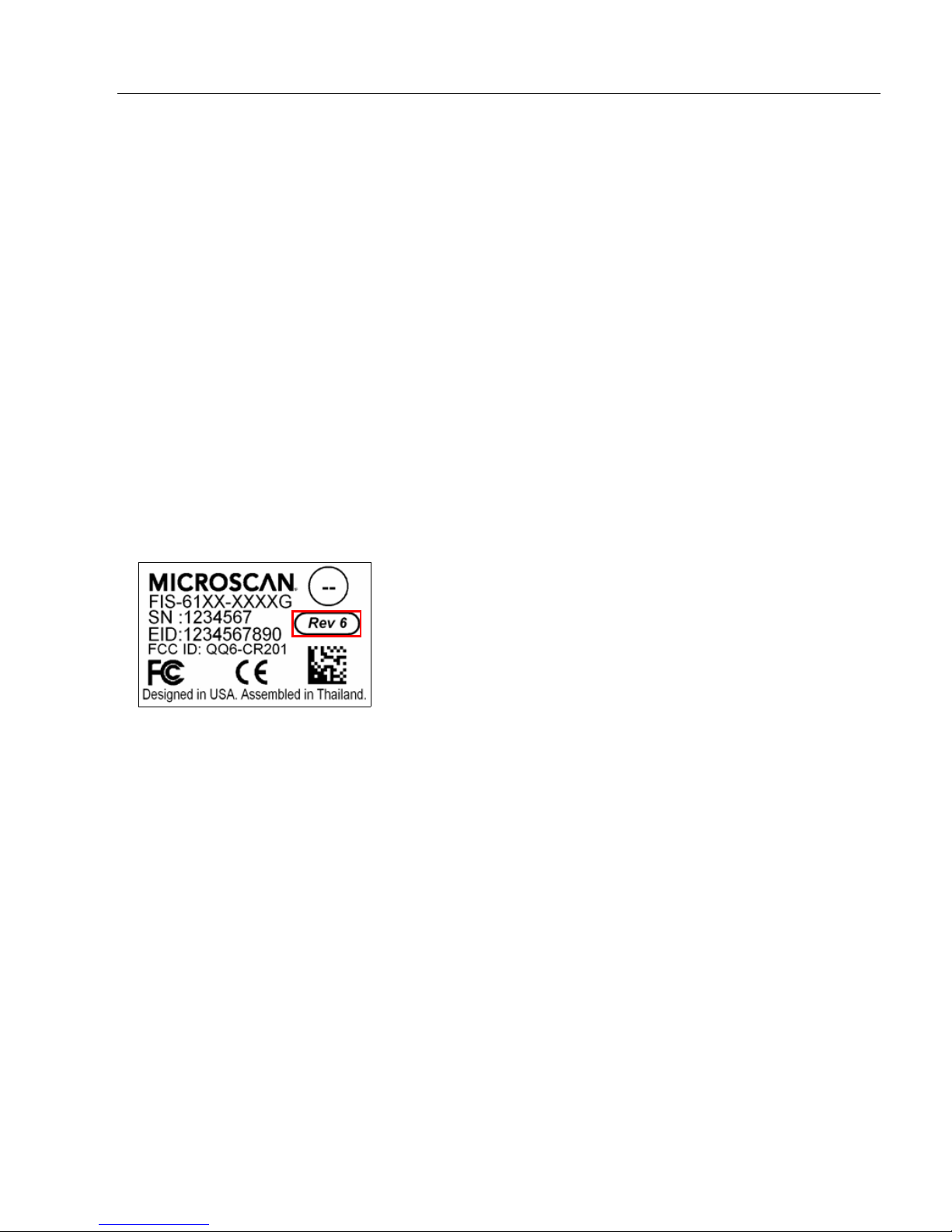
Rev 6 Hardware
MS-Q hardware has been updated to include a new image sensor. The new hardware is
referred to in this documentation as
on the label inside the battery bay.
®
model of the MS-Q Imager features added functionality that allows users to
Rev 6
. Imagers with Rev 6 hardware are clearly identified
About This Manual
This manual provides complete information on setting up, installing, an d configuring the
MS-Q Imager. The chapters are presented in the order in which the imager would be
assembled, configured, and optimized.
Highlighting
Cross-references and web addresses are highligh ted in blue bold.
References to ESP, its toolbar headings (Communications, Symbologies, I/O Parameters,
etc.) and menu headings are highlighted in Bold Initial Caps.
MS-Q Imager User’s Manual vii
Page 8

Product Labels
(Top)
(Bottom)
(Inside Battery Bay)
(Top)
(Bottom)
(Inside Battery Bay)
Product Labels
The following labels are located on the MS-Q Quadrus Imager :
The following labels are located on the MS-Q Basic Imager:
viii MS-Q Imager User’s Manual
Page 9

Introduction
Laser/LED Radiation
Wavelength: <1mW
Maximum Output: 650-700 nm
Laser Pulse Duration: 0.977 mSec.
LED Pulse Duration: 0.255 uSec.
Statement of Agency Compliance
The MS-Q has been tested for compliance with FCC regulations and was found to be
compliant with all applicable FCC Rules and Regulations.
IMPORTANT NOTE: To comply with FCC RF exposure compliance requirements, this
device must not be co-located or operate in conjunction with any other antenna or transmitter.
CAUTION: Changes or modifications not expressly approved by the party responsible for
compliance could void the user’s authority to operate the equipment.
The MS-Q has been tested for compliance to CE (Confo rmité Europée nne) st andards and
guidelines and was found to conform to applicable CE standards, specifically the EMC
requirements EN 55024, ESD EN 61000-4-2, Radiated RF Immunity EN 61000-4-3, ENV
50204, EFT EN 61000-4-4, Conducted RF Immunity EN 61000-4-6, EN 55022, Class B
Radiated Emissions, and Class B Conducted Emissions.
The MS-Q can be set to use targeting lasers. The MS-Q’s targeting laser emits Class 2M
radiation outside of the product per IEC 60825-1. Class 2M Laser/LED product. Do not
stare into the beam or view directly with optical instruments.
The MS-Q has been tested by an independent electromagnetic compatibility laboratory in
accordance with the applicable specifications and instructions.
MS-Q Imager User’s Manual ix
Page 10

Statement of RoHS Compliance
Statement of RoHS Compliance
All Microscan readers with a ‘G’ suffix in the FIS number are RoHS-Compliant. All compliant
readers were converted prior to March 1, 2007. All standard accessories in the Microscan
Product Pricing Catalog are RoHS-Compliant except 20-500013-01 and 98-000039-02.
These products meet all the requirements of the Europe an Parlia men t an d th e Co un cil of
the European Union for RoHS compliance. In accordance with th e latest requiremen ts, our
RoHS-compliant products and packaging do not contain intentionally added Deca-BDE,
Perfluorooctanes (PFOS) or Perfluorooctanoic Acid (PFOA) compounds above the maximum
trace levels. To view the documents stating these requirements, please visit:
http://eur-lex.europa.eu/LexUriServ/LexUriServ.do?uri=CELEX:32002L0095:EN:HTML
and
http://eur-lex.europa.eu/LexUriServ/LexUriServ.do?uri=OJ:L:2006:372:0032:0034:EN:PDF
Please contact your sales manager for a complete list of Microscan’s RoHS-Compliant products.
This declaration is based upon information obtained from sources which Microscan believes to be reliable, and
from random sample testing; however, the information is provided without any representation of warranty,
expressed or implied, regarding accuracy or correctness. Microscan does not specifically run any analysis on our
raw materials or end product to measure for these substances.
The information provided in this certification notice is correct to the best of Microscan’s knowledge at the date of
publication. This notice is not to be co nside red a wa rr anty or qu ality spe cificat ion. U sers a re r esp onsib le for
determining the applicability of any RoHS legislation or regulations based on their individual use of the product.
x MS-Q Imager User’s Manual
Page 11

Introduction
Warning and Caution Summary
A warning label (see above) is located on the underside of the MS-Q near the battery
locking mechanism.
Microscan voids product warranty if the hard case has been opened or tampered with in
any way . Op ening the case may put th e user at risk of laser rad iation exposure (Class 3R).
A second warning label (see above) is placed within the casing structure.
CAUTION: Use of controls or adjustments, or performance of procedures other than those
specified herein may result in hazardous radiation exposure.
In addition, a CB Test Certificate has been issued by the National Certification Board
(NCB) indicating that the MS-Q meets all safety and quality standards in accordance with
IEC 60950-1:2001, First Edition.
MS-Q Imager User’s Manual xi
Page 12

Warning and Caution Summary
xii MS-Q Imager User’s Manual
Page 13

Contents
Check Required Hardware........................................................................................................... 1-2
Assemble the Imager.................................................................................................................... 1-3
USB Interface............................................................................................................................... 1-6
PS/2 Interface............................................................................................................................... 1-7
RS-232 Interface.......................................................................................................................... 1-8
Bluetooth Interface.......................................................................................................................1-9
Batch/Battery Interface............................................................................................................... 1-10
Install ESP......................................... ............................ ... .......................................................... 1-11
Select Model............................................ .. ................................................................................. 1-12
Select Protocol and Connect to Imager...................................................................................... 1-13
1 Quick Start
This section is designed to get your MS-Q Image r up and run ning quickly so you c a n ge t a
sense of its capabilities and test sample symbols. Detailed setup information for configuring
the imager for your specific application can be obtained in the subsequent sections.
Your interface type will determine how data is received by your host. When sending data
by USB or PS/2, you must open a text editor in your host computer. When sending data
serially, you must use a terminal program such as HyperTerminal or ESP’s Terminal view
(RS-232 only).
MS-Q Imager User’s Manual 1-1
Page 14

Check Required Hardware
Check Required Hardware
Parts List for MS-Q Imagers with Cabled Handle (H2):
• One MS-Q Imager
• One H2 Handle
• One 6 ft. USB cable (Quadrus models only)
Note: PS/2 and RS-232 cables are optional and must be purchased separately.
• One Cable Clamp
• Two 2-56 x 5/16” screws, hex head, 1.5 inch-pounds (for Cable Clamp)
• Two 2-56 x 3/16” screws, hex head, 1.5 inch-pounds (for securing underside of imager
body to H2 Handle)
• Two 2-56 x 3/16” screws, hex head, 1.0 inch-pounds (for flexible 8-pin DIN connector at
back of handle)
Parts List for MS-Q Imagers with 1950 mAH Battery Handle (BH1) (Rev 5 and earlier only):
• One MS-Q Imager
• One BH1 Handle
• One 6 ft. USB cable (Quadrus models only)
Note: PS/2 and RS-232 cables are optional and must be purchased separately.
• One Cable Clamp
• Two 2-56 x 5/16” screws, hex head, 1.5 inch-pounds (for Cable Clamp)
• Two 2-56 x 3/16” screws, hex head, 1.5 inch-pounds (for securing underside of imager
body to H2 Handle)
Parts List for MS-Q Imagers with 3900 mAH Battery Handle (BH2):
• One MS-Q Imager
• One BH2 Handle
• One 6 ft. USB cable (Quadrus models only)
Note: PS/2 and RS-232 cables are optional and must be purchased separately.
• One Cable Clamp
• Two 2-56 x 5/16” screws, hex head, 1.5 inch-pounds (for Cable Clamp)
• Two 2-56 x 3/16” screws, hex head, 1.5 inch-pounds (for securing underside of imager
body to H2 Handle)
Parts List for MS-Q Imagers with Original Handle (H1):
• One MS-Q Imager
• One H1 Handle
• One 6 ft. USB cable (Quadrus models only)
Note: PS/2 and RS-232 cables are optional and must be purchased separately.
1-2 MS-Q Imager User’s Manual
Page 15
Quick Start
Flexible
Connector
Flexible
Connector
Latch
Screws
Screws
Insert screws in the through-holes
at the base of the cable clamp.
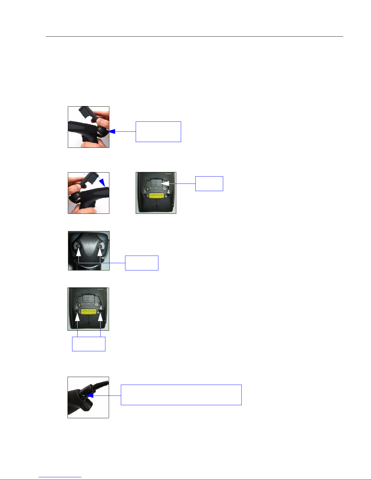
Assemble the Imager
To assemble the MS-Q Imager with Cabled Handle (H2):
1. Insert the flexible connector at the back of the H2 Handle into the MS-Q’s 8-pin DIN
connector.
2. Snap the imager onto the H2 Handle over the battery blank. Be sure that the underside
of the imager is latched at the front of the handle.
3.
Secure the flexible connector at the back of the H2 Handle with the two screws provided.
4. Secure the underside of the imager to the H2 Handle with the two screws provided.
5. Attach the cable to the bottom of the handle. Secure the cable clamp with the two
screws provided.
MS-Q Imager User’s Manual 1-3
Page 16
Assemble the Imager
Tab
Latch
Screws
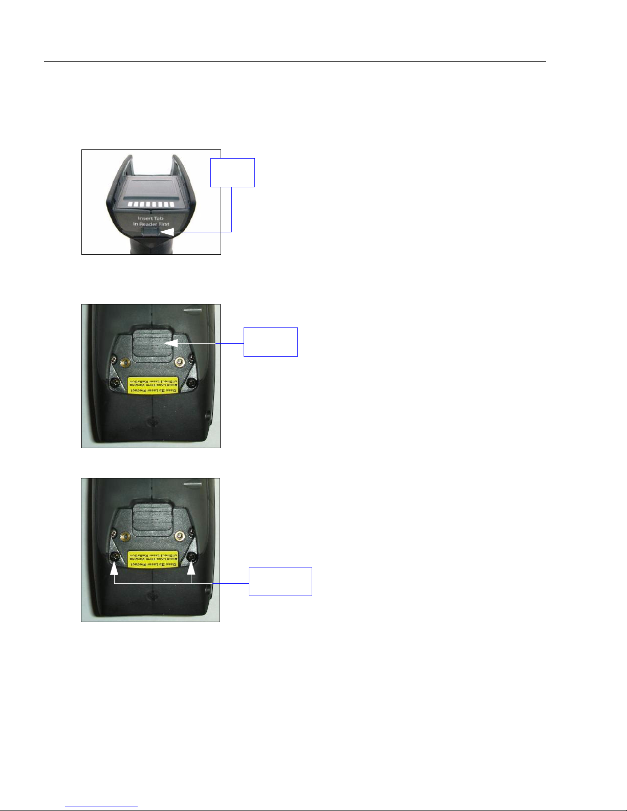
T o assemble the MS-Q Imager with Battery Handle:
1. Insert the tab on the back of the battery handle into the imager ’s recessed s lot at the
base of the battery bay.
2. Snap the imager onto the battery handle over the battery. Be sure that the underside
of the imager is latched at the front of the handle.
3. Secure the underside of the imager to the battery handle with the two screws provided.
1-4 MS-Q Imager User’s Manual
Page 17
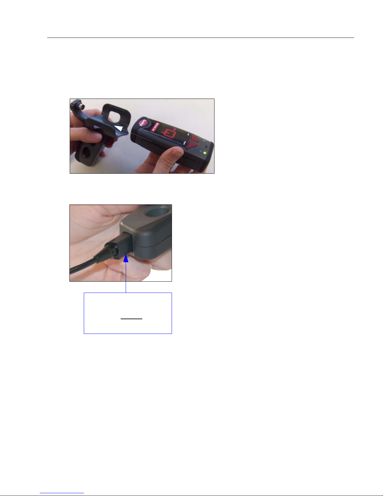
Quick Start
Grasp the connection
housing and pull to
remove. Do not pull
directly on the cable.
T o assemble the MS-Q Imager with Original Handle (H1):
1. Slide the imager into the handle’s cradle. Be sure the tabs fit into the grooves along
the sides of the imager and that the handle’s 8-pin DIN connector inserts completely
into the back of the unit.
2. Plug the USB, PS/2, or RS-232 cable into the bottom of the handle. Plug the other end
of the cable into the appropriate port on your host computer.
MS-Q Imager User’s Manual 1-5
Page 18
USB Interface
Save
Settings
Default
to USB
Default
to PS/2
Clear
All Data
Clear
XML
Rules
USB Configuration
USB Keyboard Mode
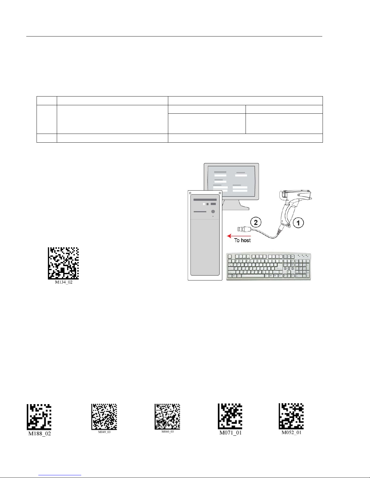
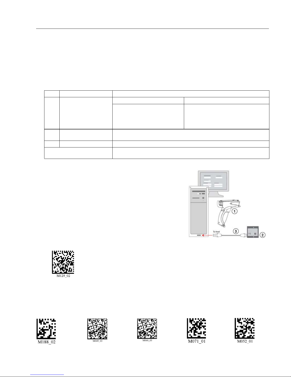
USB Interface
Note: The USB interface draws its power from the host computer.
USB Configuration
Item Description Part Number
Rev 5 Hardware Rev 6 Hardware
1 MS-Q Imager
2 USB Cable Included
Installation Steps for USB
1. Connect the USB cable (2) to the MS-Q (1).
2. Connect the USB cable (2) to the host.
You DO NOT need to power off your
host computer.
3. Open any program in your host computer
that can receive keyboard text.
Quadrus: FIS-6100-0030G,
-0035G, -0046G
Basic: FIS-6150-0020G
Quadrus: FIS-6100-0047G,
-0051G, -0053G
Basic: FIS-6150-0028G
4. Read the USB Keyboard Mode symbol
below:
5. Read the Save Settings symbol at the
bottom of this page.
You are now ready to send data to the host.
Note: If you attempt to connect to the host via USB and you have a battery installed, the
host will fail to recognize the imager for approximately 60 seconds. If you connect with a
battery blank installed, or if you install the battery after plugging in, no delay occurs.
1-6 MS-Q Imager User’s Manual
Page 19
Save
Settings
Default
to USB
Default
to PS/2
Clear
All Data
Clear
XML
Rules
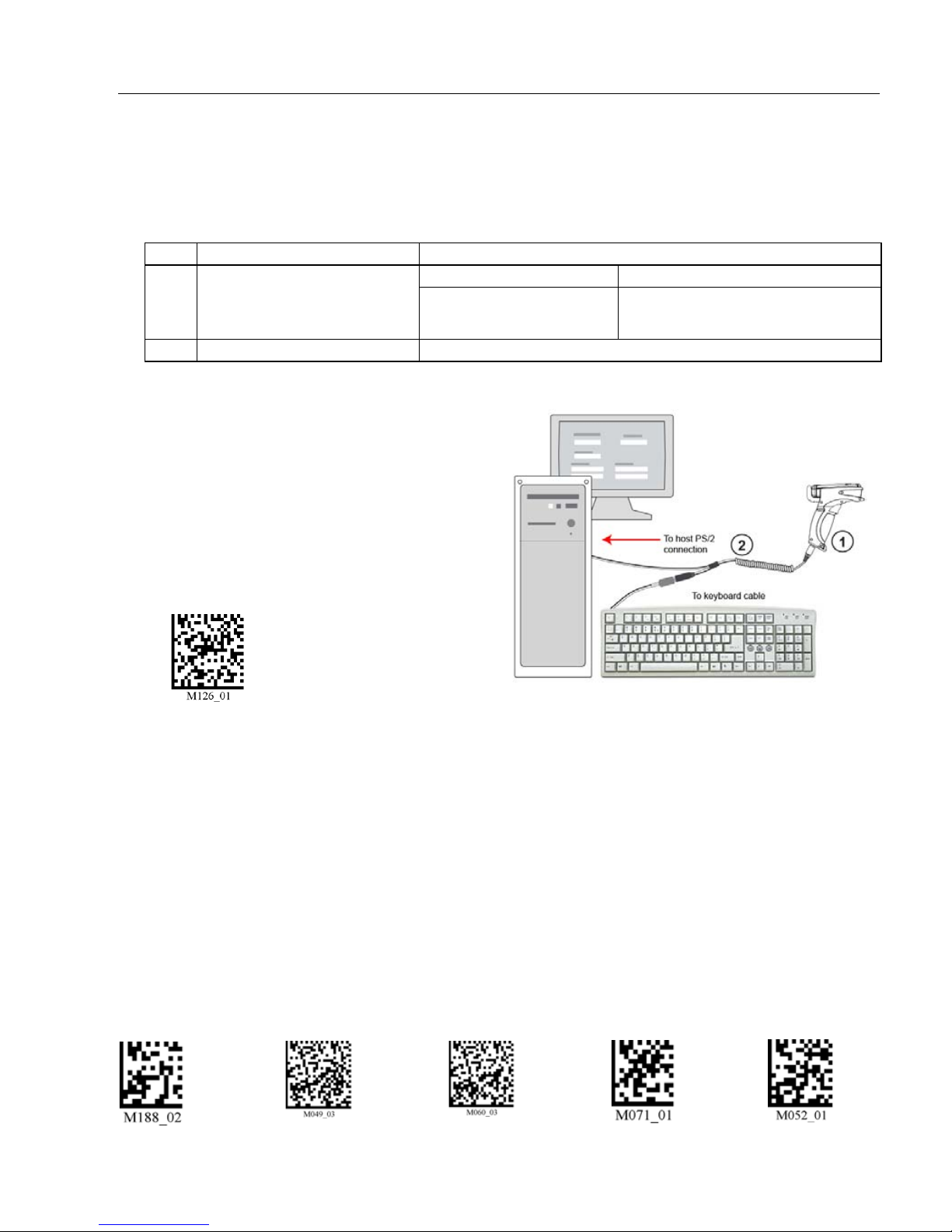
PS/2 Interface
PS/2 Configuration
PS/2 Mode
Note: The PS/2 interface draws its power from the host computer.
PS/2 Configuration
Item Description Part Number
Rev 5 Hardware Rev 6 Hardware
1 MS-Q Imager
2 Keyboard Wedge Cable 60-000018-03
Installation Steps for PS/2
1. Power-off the host and disconnect the
keyboard.
2. Attach the cable (2) to the MS-Q (1).
3. Attach the keyboard connector to the
keyboard cable and host computer as
shown.
4. Power-on the host.
5. Read the PS/2 Mode symbol below:
Quadrus: FIS-6100-0040G,
-0041G
Basic: FIS-6150-0025G
Quadrus: FIS-6100-0049G
Basic: FIS-6150-0030G
Quick Start
This connection protocol provides power to the MS-Q, and, when attached, will allow
data input from both the MS-Q and the keyboard.
6. Read the Save Settings symbol at the bottom of this page.
You are now ready to send data to the host.
Important: The MS-Q must be connected to the keyboard for the imager and the
keyboard to function in PS/2 Mode.
MS-Q Imager User’s Manual 1-7
Page 20
RS-232 Interface
Save
Settings
Default
to USB
Default
to PS/2
Clear
All Data
Clear
XML
Rules
RS-232 Configuration
RS-232 Default Settings Mode
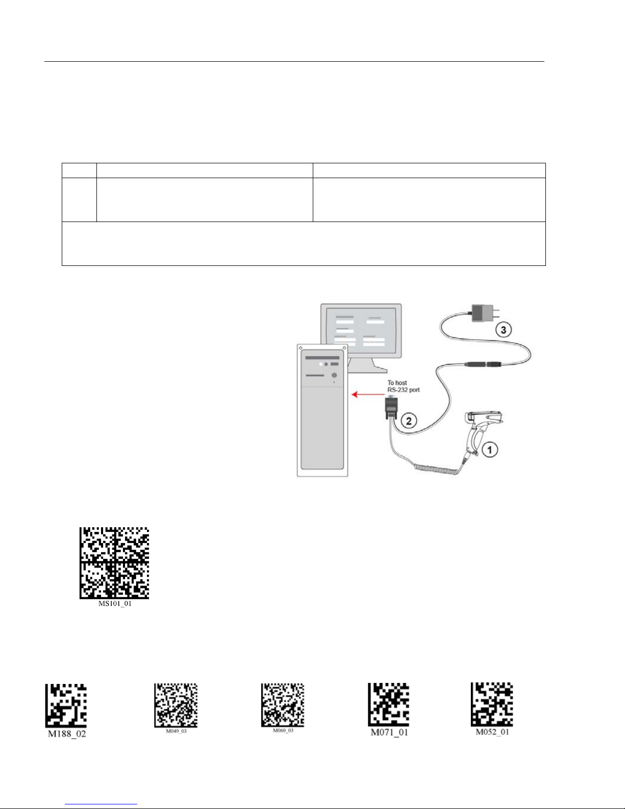
RS-232 Interface
Note:
Unlike USB and PS/2, the RS-232 inte rface does not draw its power from the host computer.
RS-232 Configuration
Item Description Part Number
Quadrus: FIS-6100-XXXXG
1 MS-Q Imager
RS-232 Kit includes:
2 RS-232 Cable
3 Power Supply
Installation Steps for RS-232
1. Power-off the host computer.
2. Connect the 8-pin mini-DIN on the
cable (2) to the MS-Q (1).
3. Connect the 9-pin D-sub connector to
the host computer’s serial port.
4. Connect the cable to the power supply .
5. Plug in the power supply (3) and
power-on the host computer.
6. Start up a terminal program (such as
ESP
’s
Terminal
and set to 57.6K baud, 8 data bits,
none parity, 2 stop bits, and none
hardware.
7. Read the RS-232 Default Settings
Mode symbol below.
view or HyperTerminal)
Basic: FIS-6150-XXXXG
Note: For the RS-232 option, order any MS-Q FIS
plus the RS-232 kit listed below.
98-000074-04 (U.S.) -05 (Europe) -06 (UK)
8. Read the Save Settings symbol at the bottom of this page.
You are now ready to send data to the host.
1-8 MS-Q Imager User’s Manual
Page 21
Quick Start
Save
Settings
Default
to USB
Default
to PS/2
Clear
All Data
Clear
XML
Rules
Bluetooth Configuration
RF Two-Way Mode
Note: If you are using an older Bluetooth Modem, read the RF Two-Way Mo de
symbol above to enable wireless communication with the host computer.
Note: See Connecting to the Bluetooth Modem via RS-232 for instructions
on how to use the Bluetooth Modem with a serial connection.
Bluetooth Interface
Note: The USB interface draws its power from the host computer.
Note: The Microscan Bluetooth modem defaults to a USB keyboard interface, and data is
displayed as if input from a keyboard.
Bluetooth Configuration
Item Description Part Number
Rev 5 Hardware Rev 6 Hardware
Quadrus: FIS-6100-0033G , -0 034G,
1 MS-Q Imager
USB Bluetooth Modem
2
(Default option)
3 USB Cable Included with kit
Note:
RS-232 options
also available
-0038G ,
-0044G, -0045G
Basic: FIS-6150-0023G, -0024G,
-0026G, -0027G
98-000076-10
98-000076-07, -08, -09
Installation Steps for Bluetooth
1. Connect the USB cable (3) from the host computer
to the Bluetooth Modem (2).
You DO NOT need to power off your host computer.
2. Open any program in the host computer that can
receive and display keyboard data.
3. Read the symbol on the Bluetooth modem’s top
label (2).
4. Read the Save Settings symbol at the bottom of
this page.
-0039G, -0042G, -0043G,
Quadrus: FIS-6100-0050
Basic: FIS-6150-0031G
G, -0054G
You are now ready to send data to the host.
MS-Q Imager User’s Manual 1-9
Page 22
Batch/Battery Interface
Save Settings
Batch/Battery Interface
Important: ESP does not support Batch/Battery Interface.
Overview
In Batch Mode a battery replaces the blank inside the MS-Q. The MS-Q is capable of
reading more than 4,000 times from a single battery charge without being physically
connected to the host. When you do connect (either by cable or wireless), the buffered
data is transferred to the host in the manner determined by your batch setup.
Batch/Battery Configuration
Item Description Part Number
Rev 5 Hardware Rev 6 Hardware
1 MS-Q Imager
2 Battery Included
Installation Steps for Batch/Battery
1. Insert the tab on the back of the battery handle into the imager ’s recessed s lot at the
base of the battery bay.
2. Snap the imager onto the handle over the battery. Be sure that the underside of the
imager is latched at the front of the handle.
3. Secure the underside of the imager to the handle with the two screws provided.
4. Select one of the Batch Setup modes - Send and Log, or Send and Buffer.
5. Read symbols as required.
6. Save settings.
7. When convenient, or when the buffer is full, open any Windows-compatible program
that can accept keyboard text (for USB and PS/2) or serial data (for RS-232 and Bluetooth).
8. Attach a cable or connect to Bluetooth to download buffered data.
Quadrus: FIS-6100-0031G , -0032G , -0036G ,
-0037G
Basic: FIS-6150-0021G, -0022G
Quadrus: FIS-6100-0048G, -0052G
Basic: FIS-6150-0029G
Batch Setup
Send and Log Mode
If you read the Send and Log Mode symbol to the left, all buffered data will be
downloaded to the host but retained in the imager’s memory whenever you
connect.
Send and Buffer Mode (Default)
If you read the Send and Buffer Mode symbol to the right, all buffered data will
be downloaded to the host and ERASED in the imager whenever you connect.
You must have a data collection progr am open be fore connecting in Send and
Buffer Mode or all buffered data will be lost.
1-10 MS-Q Imager User’s Manual
Page 23
Quick Start
USB
Connect
Mode
RS-232
Connect
Mode
USB
RS-232
Install ESP
ESP Software can be found on the Microscan Tools CD that is packaged with the MS-Q.
1. Follow the prompts to install ESP from the CD.
2. Click on the ESP icon to run the program.
Note: ESP can also be installed from the Download Center at www.microscan.com.
ESP System Requirements
• 166 MHz Pentium processor (recommended)
• Windows Vista, XP, or 2000 operating system
• Internet Explorer 5.0 or higher
• 64 MB minimum RAM
• 40 MB minimum disk space
Important: The imager must be in one of the modes below to communicate with ESP.
MS-Q Imager User’s Manual 1-11
Page 24
Select Model
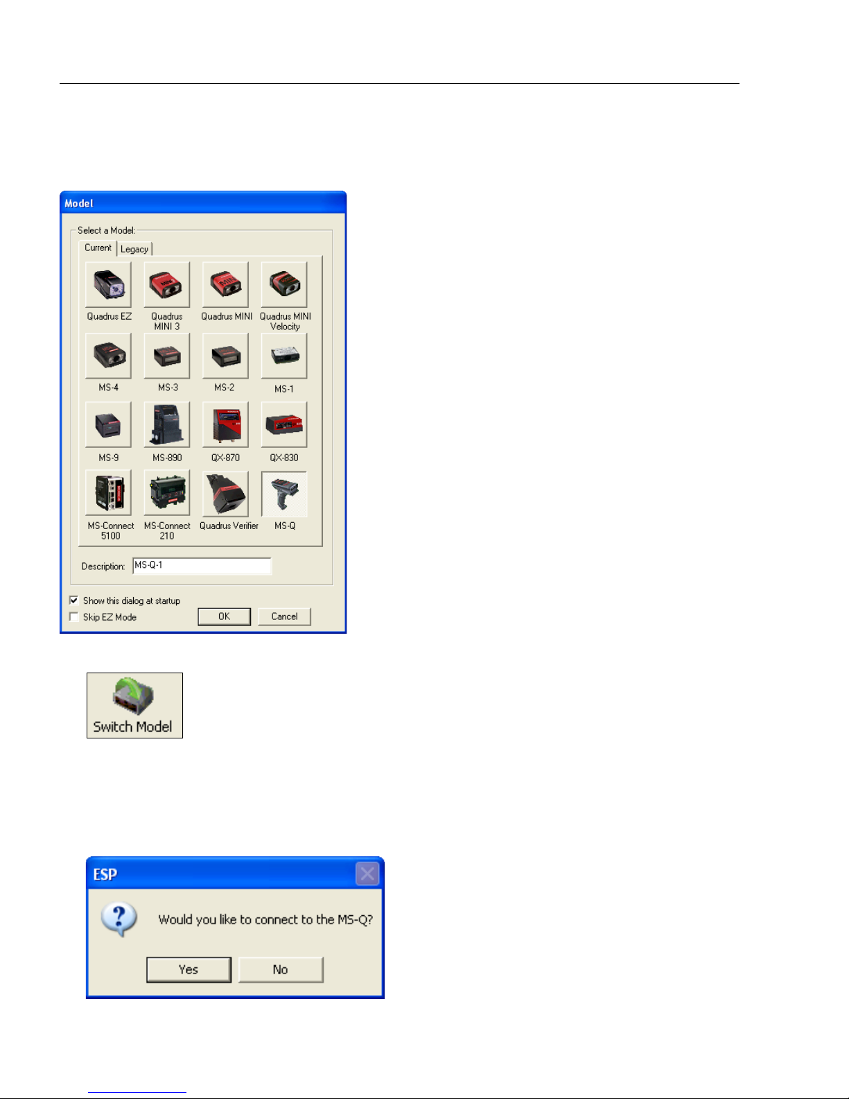
Select Model
When you start ESP, the following menu will appear:
If you need to select another model later, click Switch Model at the top of the screen.
1. Click the MS-Q button and then click OK. If you do not want to make this selection
every time you start ESP, uncheck “Show this dialog at startup”.
2. Select the default reader name (MS-Q-1), or type a name of your choice in the
Description text field and click OK.
3. Click Yes when this dialog appears:
1-12 MS-Q Imager User’s Manual
Page 25

Quick Start
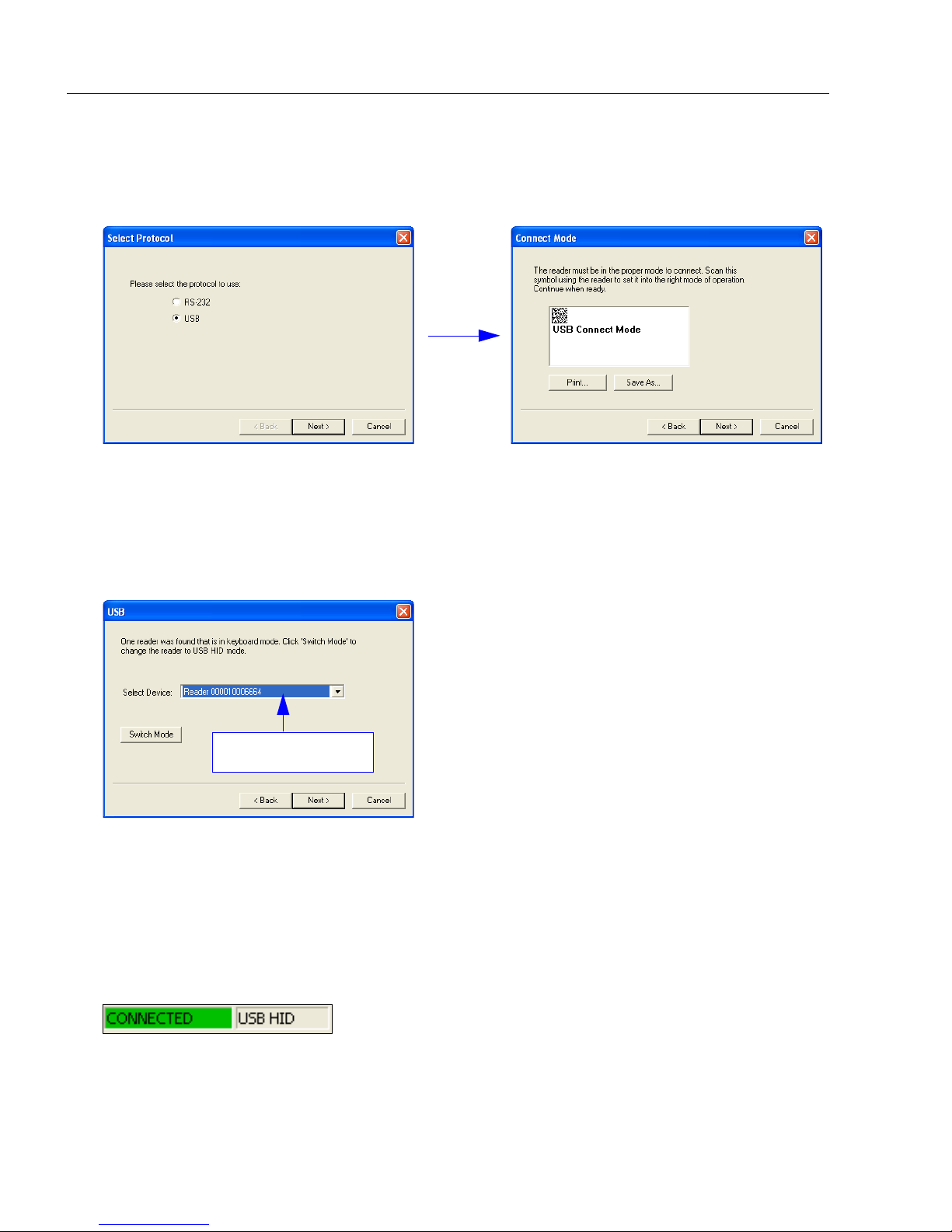
Select Protocol and Connect to Imager
RS-232
• In the Select Protocol dialog box, select the communications protocol you are using
and click Next.
•Print the RS-232 Connect Mode symbol and read it with the imager to ensure that you
are in the correct communications mode. Keep the printe d symbol in a convenient p lace
for future use.
• Click Next when you are finished.
•The Com Port dialog will then appear . Select which communications port you are using.
If you don’t see your communications port listed on the dropdown menu, select Other.
• Click Connect.
• When you are connected successfully, the CONNECTED message will appear in a
green box in the status bar at the bottom right of the screen.
If the connection attempt fails, enable a different communications port, check your port
connections, and try again. You can also check the Force Connect box and then click
the Connect button.
You are now ready to configure your imager using ESP. Subsequent sections provide
more detailed information about ESP’s configuration options.
MS-Q Imager User’s Manual 1-13
Page 26
Select Protocol and Connect to Imager
Imager ID number
USB
• In the Select Protocol dialog box, select the communications protocol you are using
and click Next.
• Print the USB Connect Mode symbol and read it with the imager to ensure that you are
in the correct communications mode. Keep the printed symbol in a convenient place for
future use.
• Click Next when you are finished.
The following dialog will then appear:
• You will see a “ Reader” ID number in the Select Device field. Click Next.
Note: If the imager is in the default USB Keyboard Mode when you attempt to connect,
the USB Reader ID dialog will tell you to click the Switch Mode button. ESP will attempt
to switch the imager to USB HID Mode. Once the imager has switched modes, click
Next.
• When you are connected successfully, the CONNECTED message will appear in a
green box in the status bar at the bottom right of the screen.
You are now ready to configure your imager using ESP. Subsequent sections provide
more detailed information about ESP’s configuration options.
1-14 MS-Q Imager User’s Manual
Page 27

2 Using ESP
EZ Mode.......................................................................................................................................2-2
Application Mode.......................................................................................................................... 2-3
Tree Controls................................................................................................................................ 2-4
Menu Toolbar............................................................................................................................... 2-5
Send/Receive............................................................................................................................ 2-14
Contents
This section is designed to help you understand the structure and application of ESP.
When you open ESP, unless otherwise specified in the ESP Preferences dialog accessible
from the Options heading on the menu toolbar, you will enter EZ Mode for initial setup.
From there, you can enter Application Mode (App Mode) and access several configuration
menus (Communications, Read Cycle, Symbologies, I/O Parameters, an Imager
setup interface, a Terminal inter face, and a Utilities interface).
ESP can be used to configure the MS-Q Imager in the following ways:
• Tree Controls: Each configuration menu contains a list of all option settings that pertain
to that specific element of imager operation. For example, the Communications menu
shows a Communications Mode command, and then the options PS/2 (A T) Keyboard,
RS-232 Serial, USB Keyboard, RF (Bluetooth), and USB Native (HID), all of which
are accessible from a dropdown menu.
• Graphic User Interfaces: Settings can be configured using such point-and-click tools
as radio buttons, tabs, spin boxes, check boxes, and drag-and-drop functions.
•
Terminal: ESP
directly to the imager by typing them in the provided text field.
’s
Terminal
interface allows you to send configuration and utility commands
MS-Q Imager User’s Manual 2-1
Page 28
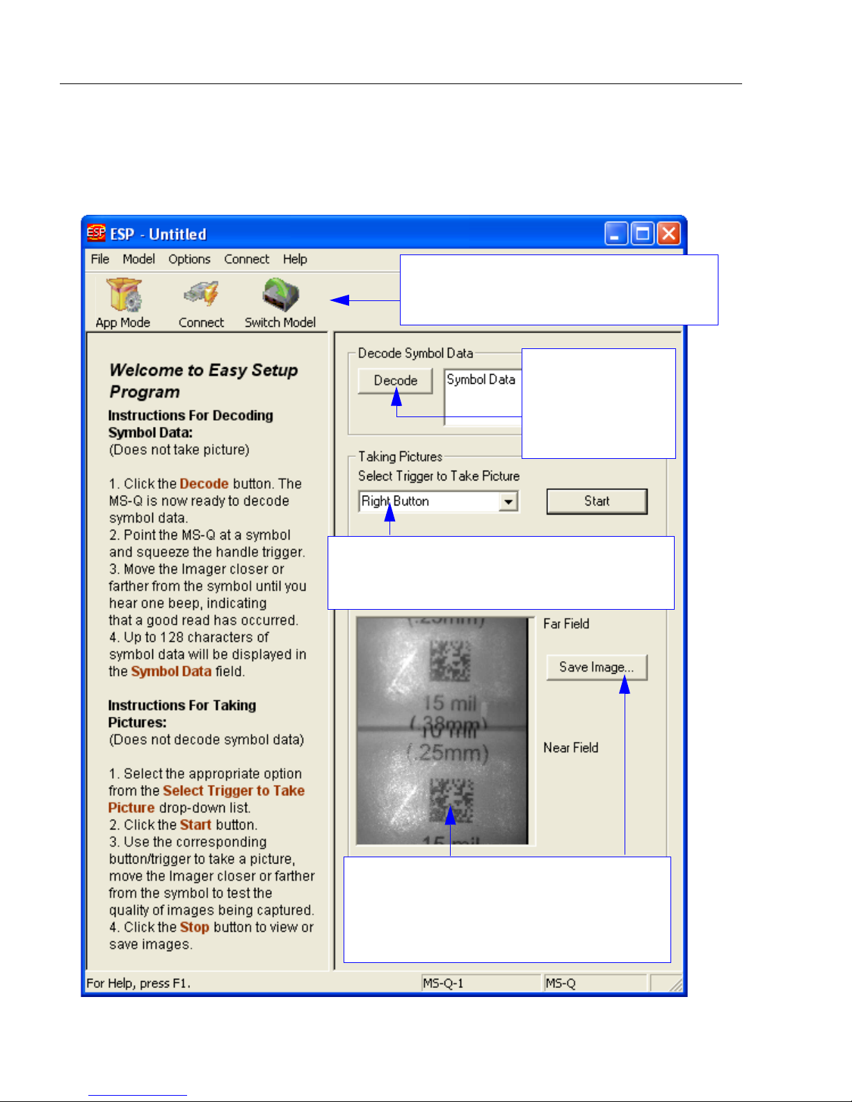
EZ Mode
The EZ Mode toolbar allows you to switch to
App Mode, check your connection parameters,
and to switch models.
The Decode button
allows you to begin
capturing images
and displaying
decoded symbol
data right away.
The T aking Pictures dropdown menu allows you to
choose which trigger will activate an image capture:
Handle Trigger, Right Button, or Left Button.
When an image is captured, it is displayed here
as a split view that shows both the near field
and far field images. Double click this image to
view it in a larger format. Click Save Image to
save it to a location of your choice.
EZ Mode
The EZ Mode screen is the first thing you will see when you start ESP. EZ Mode will help
you get your imager up and running quickly, and will acquaint you with the ESP interface.
2-2 MS-Q Imager User’s Manual
Page 29
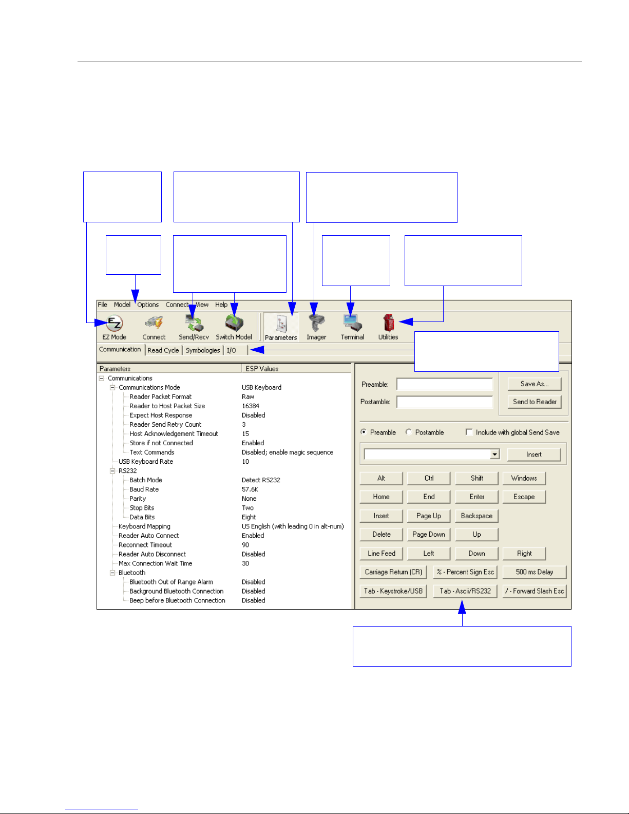
Using ESP
Menu
toolbar
Click on this icon to
return to this view from
Utilities or Terminal.
Click here for imager button
optimization, configuration,
and configuration summary.
Click these tabs to access
configuration tree controls.
Click here
to open
Terminal.
Click here to
return to
EZ Mode.
Click here for Image
Upload, Batch Files,
and Firmware.
Click these buttons to
Send and Receive
commands or switch
reader models.
Assign Preamble and Postamble characters
using the simple interface shown above.
Application Mode
Application Mode gives you access to a robust configuration environment, including
tree controls that let you make precise changes to operation parameters, and graphic
interfaces that make configuring your imager easy an d intuitive.
Note: For specific information on any of the icons shown above in the operations bar or
configuration bar, see corresponding chapters in this manual.
MS-Q Imager User’s Manual 2-3
Page 30
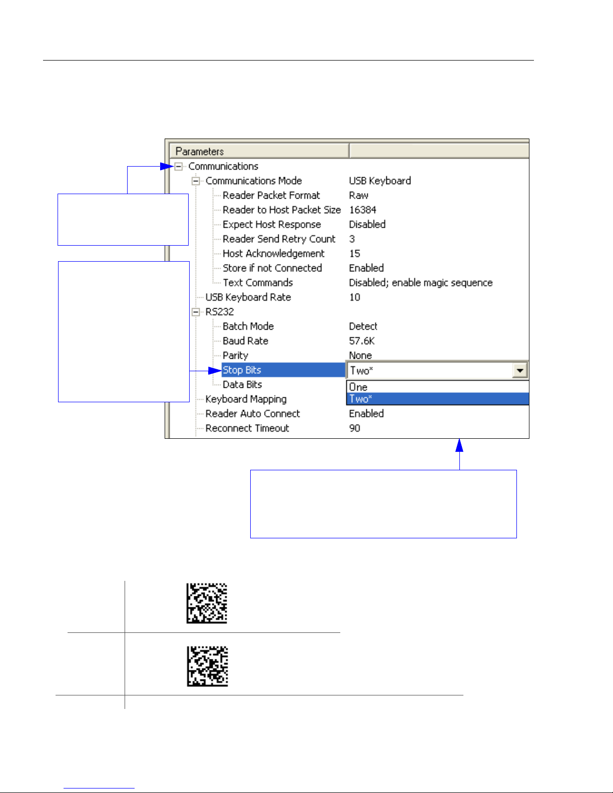
Tree Controls
1. Left click on the +/-
to expand or collapse
the tree.
4. Left click again on the open screen to complete the
selection.
5. Right click on the open screen and select Save to
Reader to implement the command in the imager.
2. Double click on
the parameter and
click once in the
selection box to
view options.
3. Place your cursor
in the selection
box, scroll down to
the setting you
want to change
and click once on
the setting.
USB
Connect
Mode
RS-232
Connect
Mode
USB
RS-232
Tree Controls
To make changes to configuration settings in the tree control menus:
The imager must be in one of the modes below to communicate with ESP.
2-4 MS-Q Imager User’s Manual
Page 31

Menu Toolbar
(Save to Imager)
(Receive Reader
Settings)
File > New
Whenever New is selected from the File menu, the default
configuration of ESP is loaded.
Open / Save
When Save or Save As is selected, the ESP configuration is
saved to the host computer’s hard drive and available whenever
the same file is selected under Open.
When you save menu changes to your hard drive, these
changes are not saved to your imager. The diagram below
shows how settings can be saved and received between ESP
and the imager, and ESP and the host hard drive.
Using ESP
Import / Export
Import converts the ASCII settings from a text file to ESP configuration settings.
Export converts the active ESP configuration settings to an ASCII text file.
MS-Q Imager User’s Manual 2-5
Page 32

Menu Toolbar
Model
The Model menu allows you to select between reader
models. When you choose another model, the current
connection with your present model will be terminated.
New Model
To connect to another model, select New Model, choose the model you want, and click OK.
All models you have selected and enabled will continue to appear in the dropdown model
menu. The New Model option is repeated when you click the Switch Model button on the
top row of icons.
2-6 MS-Q Imager User’s Manual
Page 33

Using ESP
Options
You can use the Options menu to save memos and set up ESP preferences.
Preferences will be saved and loaded into ESP the next time ESP is opened, whether or
not you save the ESP file to the host computer.
Preferences > General Tab
Reload Last File
At startup, reloads the last file saved to the computer.
Show Model Prompt
At startup, remembers the last connected model and displays it in the Connecting...
dialog whenever you attempt to connect.
Skip EZ Mode
At startup, skips EZ Mode and opens directly in App Mode.
Show Connect Prompt
At startup, displays the Would you like to connect... prompt.
Receive After Connect
At startup, loads the imager’s settings into ESP. (This is not recommended if you want to
preserve your ESP settings for future use.)
Show Both Icon and Text (Default)
Sets the toolbar to display icons and names of all operations.
Only Show Icon
Sets the toolbar to display only icons representing operations, without text.
Only Show Text
Sets the toolbar to display names of operations only, without icons.
MS-Q Imager User’s Manual 2-7
Page 34

Menu Toolbar
Terminal Tab
When
is checked, characters such as
‘CRLF’
window. When the Enhanced Format
radio button is checked, subscript and
superscript formatting is shown.
When Display incoming data even
when not in focus is checked, data
from the imager will continue to
appear in the terminal even when
ESP is not the top window
computer’s screen.
When Enable Echo is checked, the
terminal window displays user-entered
data.
Show Non-Printable Cha racters
will be displayed in the terminal
on the host
Change Keyboard Macros
Clicking the
button brings up the Function Keys
dialog. In this dialog you can select the
desired function key and then enter
your macro keystrokes in the associated
key map. For example, to make Ctrl-F2
the keystroke to send a trigger character
select F2, then in the Ctrl row , enter
<trigger character>
Then whenever the
pressed, the trigger character will start
the read cycle.
Change Keyboard Macros
and click OK.
Ctrl-F2
keystroke
is
,
Note: The F1 key is reserved for opening ESP Help and the F3 key is reserved for the
Find Next function.
Change Font
Sets the font characteristics for data received from the imager.
Change Echo Font
Sets the font characteristics of user-entered data.
2-8 MS-Q Imager User’s Manual
Page 35

Bar Code Options Tab
Using ESP
Sizing Information
Sets element size (in thousands of an inch) of symbols th at you create and print from the
Bar Code Dialog under View.
MS-Q Imager User’s Manual 2-9
Page 36

Menu Toolbar
Advanced Tab
The Auto Sync dialog on the Advanced tab allows you to determine whether Auto Sync
will be automatically enabled in sections of ESP where it is used, or if it will ask you before
it enables Auto Sync functions.
Always Ask Before Auto Sync Occurs
If you check this option box, you are then able to determine what specific Auto Sync
functions will be enabled. Receive Settings from the Re ader will automatically send
the imager’s settings to ESP when Auto Sync is enab led. Send ESP Settings to the
Reader will automatically send all imager configuration settings chosen in ESP to the
imager. Do Not Send or Receive Settings creates a condition in which Auto Sync will
not send imager settings to ESP, or send ESP settings to the imager.
Send XON with Auto-Connect
Sends an
routine.
XON (Begin Transmission
) command to the imager be fore startin g the
Auto-Connect
2-10 MS-Q Imager User’s Manual
Page 37

Using ESP
Document Memo
The information you type in the Document Memo field will appear in a context-sensitive text
box whenever your cursor hovers over the Document Memo item on the Options menu.
Model Memo
Similar to Document Memo, the information you type in the Model Memo field will appear
in a context-sensitive text box whenever your cursor hovers over the Model Memo item on
the Options menu. Memos created in Model Memo are specific to the model enable d
when the message was created.
Note:
If you do not save your current session, any memos that you have entered during the session
will be discarded, and will be unavailable in your next session.
MS-Q Imager User’s Manual 2-11
Memos must be saved in a
.esp
file if you want them to available in your next session.
Page 38

Menu Toolbar
RS-232:
USB:
Connect
Connection Wizard
When you choose to connect to the imager via the Connection Wi zard, you will first need
to select the correct protocol (see Select Protocol and Connect to Imager in Chapter 1,
Quick Start.)
When you have successfully connected to the imager you will see one of the two following
displays in the status bar at the lower right of the screen:
Settings / Options
Settings allows you to set baud rate, parity, stop bits, data bits and communications port
for the RS-232 interface before connecting.
Options allows you to auto-connect to the imager (RS-232), follow standard connection
procedure (RS-232 and USB), and disconnect the imager from ESP (RS-232 and USB).
2-12 MS-Q Imager User’s Manual
Page 39

Using ESP
View
The options in the View menu correspond to icons on the operations
toolbar (Configuration, Imager, Terminal, Utilities). Each option
allows you to configure the imager or to perform various other
functions in the chosen view.
The Imager, Terminal, and Utilities views are explained fully in
later sections.
The View menu also allows you to access the Barcode Dialog.
Barcode Dialog
In the Barcode Dialog you can directly type the text and commands you wa nt to encode.
This allows you to create configuration symbols that you can print and read with the imager.
MS-Q Imager User’s Manual 2-13
Page 40

Send/Receive
Send/Receive
To access Receive, Save, Default, and Advanced options, click the Send/Recv button.
You can also access these options by right-clicking in any of the configuration views.
Receive Reader Settings
From the Send/Recv menu, select Receive Reader Settings.
This option is useful if you want to receive the imager’s settings and save them as a file for
later retrieval. For example, if your imager has settings that you do not want to change,
choosing Receive Reader Settings will allow you to load those settings to ESP and sa ve
them as an ESP file.
Receiving the imager’s settings also assures that you will not subsequently save any
unwanted configuration changes previously made in ESP.
Select this option if you want to upload the imager’s settings to ESP. For example, if your
ESP file has a number of custom settings that you want to maintain and download to the
imager, you will lose those ESP settings if you choose to receive settings from the imager.
Save to Reader
Send, No Save
This saves ESP settings to current memory.
Send and Save
This activates all changes in current memory and saves to
the imager.
2-14 MS-Q Imager User’s Manual
Page 41

Using ESP
Default
When you select Default Current Menu Settings or Default all ESP Settings you are
only defaulting settings in
ESP
. The imager is not affected unless you download new settings.
Advanced Options
Send Current View
This is the same as Save
to Reader > Send No
Save except that only the
commands in the current
menu tree are sent.
Send Current
Command
This is the same as Send
Current View above, but
only saves the command
that is currently selected.
MS-Q Imager User’s Manual 2-15
Page 42

Send/Receive
2-16 MS-Q Imager User’s Manual
Page 43

3 Basic Operations
Step 1 Practice Targeting............................................................................................................. 3-2
Step 2 Determine Optimum Position............................................................................................ 3-3
Step 3 Select Quadrus Only or Standard Mode...........................................................................3-4
Step 4 Select Adaptive or Fixed Mode.........................................................................................3-5
Step 5 Complete Configuration.................................................................................................... 3-6
Trigger and Button Programming.................................................................................................3-7
USB Battery Charge Mode........................................................................................................... 3-8
Contents
This section explains how to practice targeting and triggering, how to begin configuring the
imager , how to perform a hardware de fault, and how to switch between Qu adrus Only and
Standard modes. (Mode switching is available for MS-Q Quadrus models only.)
MS-Q Imager User’s Manual 3-1
Page 44

Practice Targeting
Save
Settings
Default
to USB
Default
to PS/2
Clear
All Data
Clear
XML
Rules
The laser beam can be harmful to eyesight. Avoid eye contact with the
laser beam. Never point the beam at ot her people, or in a dir ection where
people may be passing.
ABCDEFGHIJKLMNOP
Step 1 — Practice Targeting
When first connecting, allow approximately 3 seconds
for the imager
to initialize.
1. Hold the imager steady and point at a symbol between 2.75
and 4.5 inches away (High Resolution Option) or between 2
inches and 19 inches away (Standard Resolution Option).
2. Squeeze and hold the trigger.
A red targeting spot will appear in front of the imager surrounded
3.
by a flashing RED LED pattern.
4. Center the laser spot on the symbol and wait a second or two for a decode.
For configuration symbols, you will hear 2 beeps when a good read occurs. For data
symbols, you will hear 1 beep when a good read occurs.
5. If no decode occurs, slowly draw away from the symbol while ho lding the laser spo t
steadily in place.
Test Symbol
Targeting Suggestions
• Typically, you should not hold the imager exac tly perp e nd icu lar to the sym bo l. Posit ion
the imager about 15 to 30 degrees to avoid specular reflection.
• Do not wave the imager side-to-side or up-and-down, or attempt to sweep across a
symbol; sudden movements will create fuzzy images and result in failed read attempts.
• The imager is omnidirectional and can read a symbol from any position (The exception
to this is with certain linear symbols; in these cases, the read area will be oriented to the
length of the symbol.)
3-2 MS-Q Imager User’s Manual
Page 45

Basic Operations
Save
Settings
Default
to USB
Default
to PS/2
Clear
All Data
Clear
XML
Rules
ABCDEFGHIJKLMNOP
Step 2 — Determine Optimum Position
1. Position the reader in front of the symbol.
• High Resolution Option: 2.75 inches for near field or 4.5
inches for far field.
• Standard Resolution Option: 4 inches for near field and 9
inches for far field.
2. Determine the optimum read position by triggering at different
distances and angles.
3. To speed up decoding, try enabling near field or far field only.
(Both fields are enabled by default.)
In general, if the symbol element size is less than 0.010” (0.025 mm), enable near field
to a focal point. If more than 0.010” (0.025 mm), try the far field focal point. A lso, i f
symbols are placed closely together, you may want to use near field to lower the risk
of reading the wrong symbol.
See Trigger and Button Programming on page 3-7 for the configuration symbols
that correspond to these settings.
Other factors to consider:
• Use Both Fields for applications in which symbols may vary significantly in size
and distance from reader.
• On Quadrus models, try Fixed Mode for even quicker decodes for symbols with
consistent size and presentation (see Select Adaptive or Fixed Mode on page 3-5).
• For a more advanced setup, see Trigger Optimization on page 7-7.
Test Symbol
MS-Q Imager User’s Manual 3-3
Page 46

Save
Settings
Default
to USB
Default
to PS/2
Clear
All Data
Clear
XML
Rules
Left
Indicator
Left
Button
Right
Button
Right
Indicator
ABCDEFGHIJKLMNOP
Select Quadrus Only or Standard Mode
Step 3 — Select Quadrus Only or Standard Mode
This feature is available for MS-Q Quadrus models only.
The firmware in the MS-Q Imager allows you to toggle easily betwe en th e specialized
Quadrus Only Mode that is preferred for DPM (Direct Part Marking) or the more generalized
Standard Mode.
As with the MS-Q Basic, in its
default configuration, the MS-Q
Quadrus’s right button and handle
also initiate reads; however, the
left button is used to toggle
between Quadrus Only and Standard
Modes.
When you press the left button
while in Quadrus Only Mode, you
will hear 3 beeps and see the left
indicator
This indicates
LED flash
RED
the imager has
3 times.
switched to Standard Mode.
When you press the left button
while in Standard Mode you will
again hear 3 beeps, but now the
left indicator LED flashes GREEN
3 times. This indicates the imager
has returned to Quadrus Only
Mode.
Note:
Reprogramming the left button
disables mode shifting.
Test Symbol
3-4 MS-Q Imager User’s Manual
Page 47

Basic Operations
Save
Settings
Default
to USB
Default
to PS/2
Clear
All Data
Clear
XML
Rules
Left
Indicator
Left
Button
Right
Button
Right
Indicator
MS-Q Settings Locked
MS-Q Settings
Unlocked
Test Symbol
ABCDEFGHIJKLMNOP
Step 4 — Select Adaptive or Fixed Mode
This feature is available for MS-Q Quadrus models only.
When you read symbols in the MS-Q default setup, the imager is in Adaptive Mode. In
this mode, when the imager is activated by the handle trigger , it attempt s to decode in both
the near field and far field resolutions, checks for both light background or dark background
images, and cycles through various gain values until a deco de is achieved. It remains with
those settings unless no decode occurs within ten attempts, in which case it resumes the
adaptive routine.
If your application involves relatively similar symbols at consistent ranges, you might
speed up decode rates by switching the imager from Adaptive Mode to Fixed Mode.
When you switch to Fixed, the optimum settings acquired in Adaptive will be locked in.
This means that the imager will not have to search through the various settings to arrive at
the optimum. However, the settings will be fixed to the distance, symbol background, etc.
that were in effect when the last decode occurred in the Adaptive Mode.
Toggling Between Adaptive and Fixed
To toggle between the Adaptive and Fixed Modes:
1. Find a position that gives you the best
decodes. (See
Position
on page 3-3.)
Determine Optimum
2.
Press both the left and right top
buttons
until you see both LED indicators
top) flash RED twice. This indicates
at the same time and hold
(on
that the imager is now in Fixed Mode.
3. To return to Adaptive Mode, press
both buttons again until the indicators
flash GREEN twice, indicating that
you have returned to Adaptive Mode.
MS-Q settings can also be locked and unlocked by reading the following symbols:
MS-Q Imager User’s Manual 3-5
Page 48

Complete Configuration
Save
Settings
Default
to USB
Default
to PS/2
Clear
All Data
Clear
XML
Rules
Left
Indicator
Left
Button
Right
Button
Right
Indicator
ABCDEFGHIJKLMNOP
Step 5 — Complete Configuration
For the MS-Q Basic, in the default configuration, both the left and right buttons as well as
the handle trigger can initiate reads.
For the MS-Q Quadrus, in the default configuration, the right button and handle trigger
also initiate reads; however, the left button is used to toggle between Quadrus Only and
Standard Modes.
Test Symbol
3-6 MS-Q Imager User’s Manual
Page 49

Basic Operations
Save
Settings
Default
to USB
Default
to PS/2
Clear
All Data
Clear
XML
Rules
Near Field Only Far Field Only
Both Fields (Default)
Both Fields (Default)
Near Field Only
Far Field Only
Both Fields (Default)
Near Field Only
Far Field Only
Both Fields
Near Field Only
Far Field Only
Continuous Read Disabled (Default)
Trigger and Button Programming
Trigger and button functionality can be configured to read just near field, just far field, or
both fields using the symbols listed below. See also Trigger Optimization on page 7-7.
Handle Trigger
Left Button
Right Button
Continuous Read
MS-Q Imager User’s Manual 3-7
Page 50

USB Battery Charge Mode
Save
Settings
Default
to USB
Default
to PS/2
Clear
All Data
Clear
XML
Rules
Enable USB Battery
Charge Mode
Default to Previous Settings
(Disable USB Battery
Charge Mode)
USB Battery Charge Mode
If you choose to charge the MS-Q Imager’s battery with a USB connection, you have the
option of using USB Battery Charge Mode. This mode dedicates most of the power
available from the USB connection to charging the battery. Read the symbol below to
enable this mode.
Note: The imager is able to read and decode symbol data while in USB Battery Charge
Mode. After each symbol decode the imager automatically returns to its battery charging
state.
3-8 MS-Q Imager User’s Manual
Page 51

Contents
Communications by ESP.................................................. ............................................................ 4-2
Communications Overview...........................................................................................................4-3
USB Interface............................................................................................................................... 4-4
PS/2 Interface............................................................................................................................... 4-5
RS-232 Interface.......................................................................................................................... 4-6
Bluetooth Interface.......................................................................................................................4-8
Batch/Battery.............................................................................................................................. 4-16
Preamble.................................................................................................................................... 4-20
Postamble................................................................................................................................... 4-21
Preamble and Postamble by ESP..............................................................................................4-22
Keyboard Mapping .................................................................................................................... 4-23
Text Commands.................. ... ..................................................... ...............................................4-24
Time Stamp................................................................................................................................ 4-25
Other Communications Settings in ESP..................................................................................... 4-26
4 Communications
This section includes connection parameters and options for communicating with the
MS-Q Imager in various interfaces.
MS-Q Imager User’s Manual 4-1
Page 52

Communications by ESP
4. Left click again on the open screen to complete the
selection.
5. Right click on the open screen and select Save to
Reader to implement the command in the imager.
2. Double click on the
parameter and click once
in the selection box to
view options.
3. Place your cursor in the
selection box, scroll down
to the setting you want to
change and click once
on the setting.
1. Left click on the + to
expand the tree.
Communications by ESP
To make changes to configuration settings in the Communications tree control:
4-2 MS-Q Imager User’s Manual
Page 53

Communications
Communications Overview
All MS-Q Imagers are shipped with a USB or PS/2 cable. You ca n also add RS-232 and
Bluetooth capabilities and configure your imager accordingly. Whenever you default the
imager, it will return to the defau lt settings of whichever interface you are using. Defaulting
the imager does not remove preamble and postamb le formatting.
Note: You must use USB Connect Mode or RS-232 Connect Mode to connect to ESP.
Once the imager is connected to ESP, you can select your communications mode and set
other communication parameters.
USB
With USB communications, the imager connects directly to the host’ s USB port from which it
draws its power. Data is displayed by any open Windows-based program that can capture
text in USB Keyboard Mode.
PS/2
With PS/2 communications, the imager connects directly to the host’s keyboard port from
which it draws its power. Data is displayed by any open Windows-based program that can
capture text in PS/2 Keyboard Mode.
RS-232
With RS-232 communications th e imager communicat es with the host throu gh a communications
program such as HyperTerminal.
Default settings for establishing RS-232 communications are:
Baud = 57.6K
Parity = None
Stop Bits = Two
Data Bits = Eight
Flow Control = None
Bluetooth
The Bluetooth version of the imager includes an internal Bluetooth wireless radio. The
radio allows for point-to-point wireless communication with other Bluetooth devices that
support serial port protocol (SPP).
Batch/Battery
The MS-Q’s Batch Mode is intended for applications that require a portable reader.
Scanned data is saved to the imager’s non-volatile memory, and can then be transferred
to a host.
MS-Q Imager User’s Manual 4-3
Page 54

USB Interface
Save
Settings
Default
to USB
Default
to PS/2
Clear
All Data
Clear
XML
Rules
USB Interface
USB Keyboard is the default interface in which data is transferred to a Windows-based
text program as keyboard data.
See USB Interface on page 1-6 for detailed steps on setting up the USB Interface.
USB Keyboard Mode
Data is entered as keyboard seque nces. You need to read this symbol
whenever you are changing from a different interface to USB.
USB Downloader Mode
This mode is the standard way of transferring unformatted, unpacketized
data to the imager through the USB port.
USB Native Two-Way Mode
This mode is used when the user needs error-corrected communication
between the MS-Q and the host the USB port.
USB Virtual COM Mode
This mode allows an MS-Q in a USB configuration to function as a virtual
serial COM port. This mode requires installation of a USB Virtual
COM driver. Contact your Microscan sales representative to request
this driver, as well as installation instructions.
4-4 MS-Q Imager User’s Manual
Page 55

Communications
Save
Settings
Default
to USB
Default
to PS/2
Clear
All Data
Clear
XML
Rules
PS/2 Interface
PS/2 Keyboard is the default interface in which data is transferred to a Windows-based
text program as keyboard data.
See PS/2 Interface on page 1-7 for detailed steps on setting up the PS/2 interface.
PS/2 Keyboard Mode
Data is entered as keyboard sequences. Read this symbol whenever you
are changing from a different interface to PS/2.
Important: The imag er must be connected to the keyboard for the
imager and the keyboard to function in PS/2 Keyboard Mode.
MS-Q Imager User’s Manual 4-5
Page 56

RS-232 Interface
Save
Settings
Default
to USB
Default
to PS/2
Clear
All Data
Clear
XML
Rules
1200
2400
4800
9600
19.2K
38.4K
57.6K (Default)
115.2K
Save Settings
RS-232 Interface
Enabling either of these modes will disable USB or PS/2 communications and require you
to default the imager or read the “USB Keyboard” symbol to return to USB.
See RS-232 Interface on page 1-8 for detailed steps on setting up the RS-232 Interface.
RS-232 Default Settings Mode
This mode is the standard way of transferr ing unforma tted, un p acketized dat a through the
RS-232 port.
You will need to read this symbol whenever you set up RS-232 communications.
Baud Rate (RS-232)
Baud Rate is the rate at which the imager and host transfer data. It only needs to be
changed if necessary to match the host setting.
4-6 MS-Q Imager User’s Manual
Page 57

Communications
Save
Settings
Default
to USB
Default
to PS/2
Clear
All Data
Clear
XML
Rules
None (Default)
Odd
Even
2 Stop Bits (Default) 1 Stop Bit
8 Data Bits (Default)
7 Data Bits
Cabled Timeout Never (Default)
Cabled Timeout 2 Hours (Default)
Parity (RS-232)
Parity is an error detection routine in which one data bit in each character is set to 1 or 0
so that the total number of 1 bits in the data field is even or odd. It o nly needs to be
changed if necessary to match the host setting.
Stop Bits (RS-232)
Stop Bits are added to indicate the end of each character. This setting should only be
changed if necessary to match the host setting.
Data Bits (RS-232)
Data Bits are the total number of bits in each character. This setting only needs to be
changed if necessary to match the host setting.
Timeout Settings (Cabled)
This feature sets the amount of time a cabled MS-Q will be enumerated before entering
Sleep Mode in order to charge the battery more quickly.
MS-Q Imager User’s Manual 4-7
Page 58

Bluetooth Interface
Bluetooth Interface
USB
For quick setup information about connecting to the Bluetooth modem via USB, see
Bluetooth Interface on page 1-9.
RS-232
Once the imager is connected via RS-232, the software on the host must be open to
receive data with a communications program such as HyperTerminal.
Baud = 57.6K
Parity = None
Stop Bits = One
Data Bits = Eight
Flow Control = None
The Bluetooth radio is a Class 1 device. If conne cted to another Class 1 device the imager
has roughly 100 meters (328 feet) line-of-sight operating range. If connected to a Class 2
or Class 3 device, the operating range may drop to match the lower range.
When the imager detects that the radio is out of range, it will store data in non-volatile
memory.
the data is sent, it will be erased from the unit’ s memory unless Batch Mode is set for
and Log
will continue to try to connect until it has reached the programmable
If the imager is in RF Two-Way Mode and Auto-Connect is enabled (which it is by
default), it will automatically attempt to reconnect with the host modem whenever:
• The imager is powered-on.
• The imager attempts to read another symbol.
Another important thing to consider is Bluetooth access. You choose Private when you
want to limit access to only one imager. You choose Shared when you want mor e than
one imager to have continuous access.
The imager will continue to try to send data until the radio is back in range. Once
Send
. If the radio cannot connect in 90 seconds, it will
emit an error beep. The imager
radio timeout setting.
4-8 MS-Q Imager User’s Manual
Page 59

Communications
RF Two-Way
Mode
Disconnect
This allows connected
imagers to send data
whenever it is read.
An imager that reads this symbol
will not connect to the modem until
re-programmed to do so.
Connecting to the Bluetooth Modem via RS-232
RF T wo-Way is the mode used when communicating with the Bluetooth modem in RS-232.
It is used when there is a need for bidirectional communication between the imager and an
appli cati on by radio frequency (i.e. T ime S t amp, Error Checking, Shared Access, etc.). The
imager receives confirmation via packet protocol verification and is 100% reliable.
To connect to the Bluetooth modem:
1. Read the RF Two-Way Mode symbol at right.
2. Read the Quick Connect Symbol located on the TOP of
your connected Bluetooth modem to establish communications.
3. Read the Save Settings symbol.
Bluetooth Communication Indicators
Bluetooth Activity
Attempting to Connect to
Bluetooth
Bluetooth Connection Failed None None 4 beeps
Bluetooth Connection
Successful
Sending Bluetooth Data Flashes Memory Status None None
Flashes BLUE Solid GREEN None
Flashes BLUE every 15
seconds
Memory LED
(LEFT indicator)
Flashes Battery Status
every 15 seconds
Battery LED
(RIGHT indicator)
a
Sound
None
a. When power is supplied via cable, the LED will remain green whenever the imager is active.
Disconnect
You may force disconn ec tio n by re ad in g th e Disconnect symbol
(in a Primary/Secondary Bluetooth connection, the imager may
not appear disconnected for 10 to 15 seconds after the command
is sent). The imager will also disconnect (go into Sleep Mode)
after a period of inactivity (see Sleep Mode Timeout on page 4-12).
Auto-Connect
After coming out of Sleep Mode or after powering-on, the imager tries to auto-connect with
the last host modem it had been connected with.
If Auto-Connect is enabled, the imager will connect to the host whenever it has data and
the imager is idle (but not asleep).
Auto-Connect (Default) Disable Auto-Connect
Important: One-W ay Mode is not supported by the Microscan Bluetooth modem. One-Way
Mode is supported by most other Bluetooth modems (Belkin, for example).
MS-Q Imager User’s Manual 4-9
Page 60

Bluetooth Interface
Save
Settings
Default
to USB
Default
to PS/2
Clear
All Data
Clear
XML
Rules
RF One-Way Mode (Maximum Range)
RF One-Way Mode (Maximum Reliability)
This mode is the standard way of transferring
unformatted, unpacketized data by radio frequency.
The Maximum Range setting optimizes the
imager for greater range but data reliability is lower.
The Maximum Reliability setting optimizes the
imager for greater reliability but th e radio ra nge
is lower.
Default RF
One-Way Mode Options
One-Way Mode is only recommended when connecting to a device well within the imager’s
specified range, or when connecting to a device without an oper ating system (a printer, for
example).
Always read the Save Settings symbol after changing connectivity options.
4-10 MS-Q Imager User’s Manual
Page 61

Communications
Private Access (Default) Shared Access
Default RF
Bluetooth Access
When the default Private Access is enabled, only one active and connected imager will
be able to send data. An imager remains active if it is connected and has not reached the
timeout period set in Sleep Mode Timeout. If it enters Sleep Mode, any other imager
enabled for Private Access can become active and maintain exclusive access as long as
it remains active itself.
When Shared Access is enabled, an imager will disconnect from the host af ter a successful
data transmission and re-connect only when it has new data to send and the host port is
available. In this mode any imager can send data, but since an imager must identify itself
each time it connects, a few seconds of latency will necessarily occur before each transmission
This does not prevent the imager from reading and decoding while awaiting access.
All imagers must have Shared Access enabled before this mode can function in any of
the imagers individually. Auto-Connect should also be enabled (otherwise, it will be
necessary to read a Quick Connect Code before every re-connect and data transmission).
.
Important: Shared Access is recommended only when RF Two-Way Mode is enabled.
Bluetooth Access by ESP
In
ESP
, Bluetooth Access settings are controlled by the
in the Communications tree control.
When Auto-Disconnect is Disabled, the MS-Q retains a connection to the host until it
enters Sleep Mode or until an explicit Disconnect command is sent (Private Access).
When Auto-Disconnect is Enabled, the MS-Q will disconnect whenever there is no data to
send to the host. When there is data to send, the MS-Q will connect, send the data, and
disconnect once again (Shared Access).
Reader Auto-Disconnect
command
MS-Q Imager User’s Manual 4-11
Page 62

Bluetooth Interface
Save
Settings
Default
to USB
Default
to PS/2
Clear
All Data
Clear
XML
Rules
90 Seconds (Default)
15 Minutes
1 Hour
5 Minutes
30 Minutes
2 Hours
10 Minutes
Default RF
Sleep Mode Timeout
Following a period of inactivity, the imager will go into Sleep Mode, during which it will no
longer signal its presence to the m odem. It leaves Sleep Mode whenever it is powered-on
or a read is attempted.
When the imager leaves Sleep Mode, there will be approximately 5 seconds of connect
time before a symbol can be read and transmitted.
Read the symbols below to set the period of time before Bluetooth enters Sleep Mode.
Note: Increasing the amount of time before the imager times out will decrease battery life.
Note: If the imager has power (USB cable, power cable, etc.) it will disconnect based on
Cabled Timeout settings.
4-12 MS-Q Imager User’s Manual
Page 63

Communications
Save
Settings
Default
to USB
Default
to PS/2
Clear
All Data
Clear
XML
Rules
Enable Out-of-Range Beep
Enable Out-of-Range Vibrate
Enable Out-of-Range
Beep and Vibrate
Disable Out-of-Range Notification
(Default)
Default RF
Disable Auto-Save (Default)
Enable Auto-Save
Default RF
Out-of-Range Notification
This feature allows you to set the imager to beep or vibrate when the Bluetooth rad io is out
of range. Read the symbols below to set the desired Out-of-Range Notification profile.
Auto-Save Last Bluetooth Address
If the MS-Q is saved in the proper RF communication mode, enabling Auto-Save will
allow the imager to automatically save the last device to which it was connected. This
eliminates the need to Save Settings after reading the Quick Connect Code.
MS-Q Imager User’s Manual 4-13
Page 64

Bluetooth Interface
Save
Settings
Default
to USB
Default
to PS/2
Clear
All Data
Clear
XML
Rules
Lockout Link Mode
Unlock Link
Lockout Link Mode
Lockout Link Mode can be used to establish a permanent conn ection between the MS-Q
and a Bluetooth Modem.
• Read the Quick Connect Code on the top of th e mod em to which you wish to est ablish
a permanent link.
• Listen for the single beep to indicate a successful connection.
• Read the Lockout Link Mode symbol below.
To reassign a permanent connection between the modem and a different MS-Q, read the
Unlock Link symbol below . Follow the above instructions with the new imager to establish
the new connection.
4-14 MS-Q Imager User’s Manual
Page 65

Communications
Save
Settings
Default
to USB
Default
to PS/2
Clear
All Data
Clear
XML
Rules
RS-232 Bluetooth Mode
USB Bluetooth Mode
Connecting via RS-232 with a USB Bluetooth Modem
In some applications, it may become necessary to connect to a host via RS-232 using a
USB Bluetooth Modem. The following steps allow you to convert a USB Bluetooth connection
to RS-232.
1. Plug the USB cable into the Bluetooth Modem and the
host computer’s USB port.
Important: You must use a charged MS-Q battery for
this procedure to work properly.
2. Read the Quick Connect Code on the top label of the
Bluetooth Modem.
You will now be able to decode and send data to a program
in the host computer that can receive and display data.
3. Read the RS-232 Bluetooth Mode symbol and then
the Save Settings symbol at the bottom of this page.
4. Plug the Bluetooth Modem into an RS-232 connector
and power supply.
5.
Open a terminal program and connect using the following
port settings:
Baud = 9600
Parity = Even
Stop Bits = One
Data Bits = Seven
Flow Control = None
6. Read the symbol below to return to USB Bluetooth Mode, and then read the Save
Settings symbol at the bottom of this page.
MS-Q Imager User’s Manual 4-15
Page 66

Batch/Battery
Batch/Battery
See Batch/Battery Interface on page 1-10 for instructions on installing the battery.
The battery automatically charges every time a cable interface is attached to the imager
and the host is powered-on.
The RS-232 interface power adapter must be plugged into a wall socket for the battery to
charge.
In USB and PS/2 interfaces, the imager and battery draw their current from the host
computer.
Typical Battery Charge Times
USB and PS/2 RS-232 Battery Charger
6 to 8 hours 6 to 8 hours 4 hours
Typical Battery Usage when not connected to the host:
• Up to 8 hours Standby
• Up to 4,000 reads
Batch/Battery Communication Indicators
Imager Activity
Successful Decode and
Data Storage
Batch Memory Full Solid RED None 3 beeps
a. When power is supplied via cable, the LED will remain green whenever the imager is active.
Memory Status None 1 beep
Memory LED
(LEFT indicator)
Battery LED
(RIGHT indicator)
a
Sound
Important: When the memory LED turns RED, you must download or data will be lost.
4-16 MS-Q Imager User’s Manual
Page 67

Communications
Save
Settings
Default
to USB
Default
to PS/2
Clear
All Data
Clear
XML
Rules
Send and
Buffer Mode
(Default)
Log Only
Mode
Send and
Log Mode
Batch Mode Options
The MS-Q Imager features three different Batch Modes for applications requiring a portable
imager. Batch Modes allow a user to save data to the imager’s non-volatile memory and
later transfer that data to a host computer when connected, either by USB or RS-232
cable, or by Bluetooth.
The imager’s dedicated batch memory is a minimum of 1MB.
The imager will automatically detect when the Bluetooth radio is out of range, or a USB or
RS-232 cable is detached (provided it is plugged into a power supply). If a battery is
installed, the imager will switch to Batch Mode and buffer the data in non-volatile memory.
If you read the Send and Buffer Mode symbol at left, all data in
the buffer will be downloaded to the host and ERASED in the
imager whenever you connect.
You must have a data collection program open before connecting
in this mode or all buffered data will be lost.
Important: Once the unit is reattached to a cable or enters
within radio range, decoded data will NOT be saved to non-volatile
memory. If you are using an RS-232 connection, the im ag er
must be in Batch Mode for the data to be stored.
In
Log Only Mode
, the imager will only store data in non-volatile
memory. You can only send the data by sending the Transfer
All Data command. Once the memory has been transferred to a
host, all of the data will still reside in memory.
You must read the Delete Data symbol to clear memory.
If you read the Send and Log Mode symbol to the left, all data in
the buffer will be downloaded to the host but retained in the
imager’s memory whenever yo u connect. Th e data can be
transferred again by reading the Transfer All Data symbol.
Reconnecting to the Host
When reconnected to the host, or when the Bluetooth Radio is back in range, the imager
will automatically detect the connection and, depending on the Batch Mode, transfer or log
(retain) buffered data. The imager can be considered connected if:
•The Bluetooth radio is in range and active.
•The USB cable is attached to a host computer and the imager is enumerated.
• It is in RS-232 Mode and the cable is attached to a host with power supply plugged in.
•The RS-232 cable is a ttached to a host compute r with power supply and the imager is in
Batch Mode.
MS-Q Imager User’s Manual 4-17
Page 68

Batch/Battery
Save
Settings
Default
to USB
Default
to PS/2
Clear
All Data
Clear
XML
Rules
Transfer All
Data
Transfer New
Data
Delete Data
Enable Auto-Transfer
Buffer Memory (Default)
Disable Auto-Transfer
Buffer Memory
Transferring and Deleting Data
The MS-Q Imager has three diff erent commands that can transfer data or delete data in
memory.
All data in memory is sent every time the Transfer All Data
symbol is read.
Every time the Transfer New Data symbol is read, only the
data in memory that hasn’t been sent will be transferred.
Note: This command is not applicable in Log Only Mode. If
you are in Log Only Mode, use Transfer All Data.
Reading the Delete Data symbol will erase all data in the
imager’s non-volat ile me m ory.
Auto-Transfer Buffer Memory
By default, when the MS-Q re-connects to the host, it will automatically transfer any data in
memory. If the application on your host computer is not ready, the imager will send the
data anyway, and the data could be lost. If you do not wish for the imager to send data
immediately upon connection, read the Disable Auto-Transfer Buffer Memory symbol.
4-18 MS-Q Imager User’s Manual
Page 69

Communications
Save
Settings
Default
to USB
Default
to PS/2
Clear
All Data
Clear
XML
Rules
RS-232 Batch
(Cable Detect)
RS-232 Cabled - No Power
RS-232 Batch Features
RS-232 interfaces will NOT detect when an RS-232 cable is removed unless the power
supply for that cable is plugged in. If your power cable is unplugged, you still enter Batch
Mode by reading the RS-232 Batch (Cable Detect) symbol below.
However, when you re-connect to the RS-232 power supply you must enable RS-232
Cabled - No Power to put the imager back in Cabled mode. In RS-232 Cabled, the
imager has no way to check if it is unplugged. Therefore, collected data will be automatically
sent out the disconnected port (i.e., it will not buffer the data—it will only log it, assuming
the imager is in Send and Log Mode.) This data would be lost if the imager were in Send
and Buffer Mode.
The opposite is true for RS-232 Batch (Cable Detect). In this mode, the imager assumes
that it is NOT cabled. It will buffer and log the data unless you plug it into the cable that has
a power supply. The imager will be able to detect the power source and will automatically
switch to cabled operation.
Important: When the imager is in RS-232 Cabled Mode, it will behave as if it is being
attached to a cable when it is placed in the battery charger. This will cause it to download
collected data, and the data will be erased from memory. To disable this feature, read the
RS-232 Batch (Cable Detect) symbol.
MS-Q Imager User’s Manual 4-19
Page 70

Preamble
Save Settings
Comma
Space Tab (USB Only)
Tab Erase All
Preamble Data
Carriage Return
Line Feed
Important: Use
only with serial
applications.
Erase Preamble and Postamble Data
Preamble
A preamble is a character or series of characters that is added to the beginning of a
decoded data string. Preamble characters will appear in the order that they are enabled
(left to right). For example, if you enable a comma and then a space, and then decode a
symbol c o ntaining the data ‘ABC’, y o ur output will look like this:
, ABC
The only limit to the number of preambles enable d is the total memory size available.
Important: Be sure to save all settings before reading any of the following preamble
symbols—otherwise your settings may be lost.
Set the desired preamble by reading the appropriate symbol below.
Note: To erase all preamble and postamble data, read the followin g symbol:
4-20 MS-Q Imager User’s Manual
Page 71

Communications
Save Settings
Carriage Return
Comma Line Feed
Carriage Return
Line Feed
Space Enter
Tab
Tab (RS-232 Only)
Erase / None
Important: Use
only with serial
applications.
Important: Use
only with serial
applications.
Important: Use
only with serial
applications.
Important: Use
only with USB or
PS/2 Keyboard
modes.
Important: Use
only with USB or
PS/2 Keyboard
modes.
Important:
Reading this
symbol will
erase all
postamble
data.
Erase Preamble
and Postamble
Data
Note: To erase
all postamble
and preamble
data, read the
symbol at right:
Postamble
A postamble is a character or series of characters that is added to the e nd of a decoded
data string. Postamble characters will appear in the order that they are enabled (left to
right). For example, if you enable a space and then a comma, and then decode a symbol
conta ining the data ‘ABC’, your o utput will look like this:
ABC
,
The only limit to the number of postambles enabled is the total memory size availa ble.
Important: Be sure to save all settings before reading any of
the following postamble symbols—otherwise your settings may
be lost.
Set the desired postamble by reading the appr opriate symbol below.
MS-Q Imager User’s Manual 4-21
Page 72

Preamble and Postamble by ESP
Scroll through a list of all preamble
and postamble options, and then
click Insert.
In addition to typing directly
in the text fields and selecting
from the dropdown menu,
you can also click any of
these preset buttons to set a
preamble or postamble.
Save pre- and postamble
settings and send them to
the reader.
When you type ASCII characters directly into the Preamble
or Postamble text fields and then click Send to Reader,
those preamble or postamble characters are enabled and
will appear in data output.
Preamble and Postamble by ESP
Characters can also be added to the beginning and end of data strings using ESP. There
are a few different ways to do this, using the interface shown below.
You will see the Communications tree control on the left, and the Preamble/Postamble
interface on the right.
4-22 MS-Q Imager User’s Manual
Page 73

Communications
Save
Settings
Default
to USB
Default
to PS/2
Clear
All Data
Clear
XML
Rules
US English, No
Leading 0 (Default)
US English,
Leading 0
US English, Ctrl + Char.
for Non-Printable ASCII
French German
Japanese
Universal Keyboard
Custom Keyboard
Keyboard Mapping
The Keyboard Mapping feature provides alternatives for keyboards that do not co nfo r m
to US English mapping.
Note: Universal Keyboard mapping is slightly slower than the other language-specific
options, because it maps data by reference to the full set of ASCII characters. The
advantage of Universal Keyboard mapping is that it allows any language and keyboard
layout to be mapped.
Important: Keyboard Mapping is not to be confused with USB Keyboard Mode, which
has an entirely different function—namely to enable USB cabled communications. (See
USB Interface on page 1-6).
Keyboard Mapping by ESP
MS-Q Imager User’s Manual 4-23
Page 74

Text Commands
Save
Settings
Default
to USB
Default
to PS/2
Clear
All Data
Clear
XML
Rules
Enable Text Commands
(Default)
Disable Text Commands
When Text Commands are set to
Enabled; Suppress Echo, text
that a user enters in the terminal
will not be shown. When Text
Commands are set to Enabled;
Suppress Echo and Responses,
neither user-entered data or reader
responses will be shown, and only
decoded symbol data will appear in
the terminal.
See Terminal Right-Click Menu
on page 8-6 for a way to change
Echo settings directly in the terminal
view.
When Magic Sequence is enabled, it allows
the user to enable
T ext Commands
by entering a predetermined series of keystrokes.
Enter the magic sequence in
this text field and click Send.
Once the magic sequence has been sent, you can send text co mmands from t he same text field.
Text Commands
When the Text Commands feature is enab led , th e MS- Q ca n ac cep t te xt com m a nd s vi a
RS-232 or RF connections.
Text Commands by ESP
Entering Magic Sequence
The magic sequence is ;>PA followed by a numeric value of 1, 3, or 7.
1 = Enable Text Commands
3 = Enabled; Suppress Echo
7 = Enabled; Suppress Echo and Responses
In the example below, the magic sequence entered will Enable Text Commands and
Suppress Echo and Responses.
4-24 MS-Q Imager User’s Manual
Page 75

Communications
Save
Settings
Default
to USB
Default
to PS/2
Clear
All Data
Clear
XML
Rules
Enable Time Stamp
Disable Time Stamp
Clear XML Rules
Time Stamp
When Time Stamp is enabled, the time of each decode will be appended to data output as
a preamble.
Note: The Enable Time Stamp command is an XML rule. To clear time stamp data, read
the Clear XML Rules command.
Example: 01014627:ABCDEFGHIJKLMNOP
Day is: 01
Hour is: 01
Minutes are: 46
Seconds are: 27
Data is: ABCDEFGHIJKLMNOP
MS-Q Imager User’s Manual 4-25
Page 76

Other Communications Settings in ESP
Other Communications Settings in ESP
Some
programming symbols. These options are explained below.
ESP
Communications options are unique to the software, and do not have corresponding
Reader Packet Format
Data that is sent from the imager to the host in Raw format is sent without packet framing
or check characters. One-Way communication is in a raw format, no response is expected
from the host, and data is not resent.
Packetized data is sent with framing (a preamble communicating the amount of dat a to be
transmitted, and a postamble containing error detection) and check characters, and a
response is expected from the host. Two-Way communication is in packet format.
Reader to Host Packet Size
The Reader to Host Pack et Size is the amount of data (in bytes) that is sent to the host in
packet format. This feature allows you to set the maximum allowable packet size.
Expect Host Response
When Expect Host Response is enabled, the imager will re-transmit data if it doesn’t
receive acknowledgement from the host.
Reader Send Retry Count
Reader Send Retry Count sets the number of times the imager will re-transmit data
before abandoning further send attemp t s. The minimum r etry count i s 1, which represen t s
the initial transmission.
Host Acknowledgement Timeout
The Host Acknowledgement T imeout is the amoun t of time (in seconds) that the imager
will wait for an acknowledgement from the host before re-sending data.
4-26 MS-Q Imager User’s Manual
Page 77

Communications
Store If Not Connected
When this feature is enabled, the imager does not store dat a in non-volatile m emory when
there is not an active connection to a host. When disabled, the imager follows normal
buffer operation.
Reconnect Timeout
When Auto Reconnect is enabled, the imager will reconnect to the host whenever there
is data to be sent, but only within the time limit (in seconds) set for Reconnect Timeout.
See also Transferring and Deleting Data on page 4-18.
Max Connection Wait Time
When a connection from the imager to the host is explicitly requested (such as when a
Bluetooth Quick Connect Code is read), the imager will
amount of time (in seconds) set for
Max Connection Wait Time
attempt a connection for the
.
Background Bluetooth Connection
Background Bluetooth Connection allows the user to begin decoding symbol data
before a Bluetooth connection is established.
When this feature is disabled, the Bluetooth connection must be confirmed before decoding
can begin.
Beep Before Bluetooth Connection
When this feature is enabled, a second beep is emitted while re ading the Blueto oth Quick
Connect Code, but before the Bluetooth connection is established
When this feature is disabled, the second beep is emitted upon connection to the Bluetooth
Modem.
.
MS-Q Imager User’s Manual 4-27
Page 78

Other Communications Settings in ESP
4-28 MS-Q Imager User’s Manual
Page 79

Contents
Symbologies by ESP.................................................................................................................... 5-2
Aztec............................................................................................................................................. 5-3
Codabar........................................................................................................................................5-4
Codablock F .................................................................................................................................5-5
Code 11........................................................................................................................................ 5-6
Code 39........................................................................................................................................ 5-7
Code 93........................................................................................................................................ 5-9
Code 128....................................................................................................................................5-10
Composite .................................................................................................................................. 5-11
Data Matrix................. ... ............................................................................... ... ........................... 5-12
Interleaved 2 of 5........................................................................................................................ 5-13
Maxicode.................................................................................................................................... 5-14
Matrix 2 of 5................................................................................................................................ 5-15
MicroPDF417.............................................................................................................................. 5-16
MSI Plessey...................... ..................................................... .....................................................5-17
NEC 2 of 5................................... ... ............................ ............................ ... ................................. 5-18
PDF417...................................................................................................................................... 5-19
Pharmacode...............................................................................................................................5-20
Postal Symbologies............................................... ............................................................. ........ 5-22
QR Code..................................................................................................................................... 5-24
GS1 DataBar.............................................................................................................................. 5-25
UPC/EAN/JAN............................................................................................................................ 5-26
Symbology Identifier...................................................................................................................5-27
5 Symbologies
This section describes the various symbol types that can be read and decoded by the
imager. Symbologies are arranged alphabetically.
See
http://www.aimglobal.org/standards/aimpubs.asp
MS-Q Imager User’s Manual 5-1
for additional information.
Page 80

Symbologies by ESP
4. Left click again on the open screen to complete
the selection.
5. Right click on the open screen and select Save to
Reader to implement the command in the imager.
2. Double click on the
parameter and click once
in the selection box to view
options.
3. Place your cursor in the
selection box, scroll down
to the setting you want to
change and click once on
the setting.
1. Left click on the +
to expand the tree.
Symbologies by ESP
To make changes to configuration settings in the Symbologies tree control:
5-2 MS-Q Imager User’s Manual
Page 81

Save
Settings
Default
to USB
Default
to PS/2
Clear
All Data
Clear
XML
Rules
Aztec
Read the following symbols to enable/disable Aztec settings:
Aztec On Aztec Off (Default)
Aztec by ESP
Symbologies
Sample Aztec Symbol
Note: Aztec is available only in Standard Mode.
MS-Q Imager User’s Manual 5-3
Page 82

Codabar
Save
Settings
Default
to USB
Default
to PS/2
Clear
All Data
Clear
XML
Rules
ESP allows you enable a checksum, or
to enable a check sum and remove it
from the decode result.
Codabar
Read the following symbols to enable/disable Codabar settings:
Codabar On (Default) Codabar Off
Codabar by ESP
Sample Codabar Symbol
Note: Codabar is available only in Standard Mode.
5-4 MS-Q Imager User’s Manual
Page 83

Save
Settings
Default
to USB
Default
to PS/2
Clear
All Data
Clear
XML
Rules
Codablock F
Read the following symbols to enable/disable Codablock F settings:
Codablock F On Codablock F Off (Default)
Codablock by ESP
Note: ESP offers Codablock A in addition to Codablock F.
Symbologies
Important: When Codablock F and Code 128 are both enabled, there is some risks of
mistakenly decoding a damaged Codablock F symbol as a Cod e 128 symbol. Therefore,
whenever possible, Code 128 should be disabled when Codablock F is enabled.
Sample Codablock F Symbol
Note: Codablock F and Codablock A are available only in Standard Mode.
MS-Q Imager User’s Manual 5-5
Page 84

Code 11
Code 11
Read the following symbols to enable/disable Code 11 settings:
Code 11 Enabled with 2 Code 11 Disabled
Checksum Digits (Default)
Enabled with 1 Checksum Enabled with 2 Checksum Digits
Digit and Stripped from Result
Enabled with 1 Checksum Digit
and Stripped from Result
Code 11 by ESP
Note: “No Report” in ESP has the same meaning as “Stripped from Result”.
Sample Code 11 Symbol
Note: Code 11 is available only in Standard Mode.
5-6 MS-Q Imager User’s Manual
Page 85

Save
Settings
Default
to USB
Default
to PS/2
Clear
All Data
Clear
XML
Rules
Code 39
Read the following symbols to enable/disable Code 39 settings:
Code 39 On (Default) Code 39 Off
Enable Checksum Disable Checksum (Default)
Enable Checksum and Strip from Result
Symbologies
Code 39 Extended Code 39 Extended
Full ASCII On Full ASCII Off (Default)
Code 39 Narrow Margins On Code 39 Narrow Margins Off (Default)
Code 39 Trioptic On Code 39 Trioptic Off
MS-Q Imager User’s Manual 5-7
Page 86

Code 39
Save
Settings
Default
to USB
Default
to PS/2
Clear
All Data
Clear
XML
Rules
Code 39 by ESP
Sample Code 39 Symbol
Sample Code 39 Trioptic Symbol
Note: Code 39 is available only in Standard Mode.
5-8 MS-Q Imager User’s Manual
Page 87

Save
Settings
Default
to USB
Default
to PS/2
Clear
All Data
Clear
XML
Rules
Code 93
Read the following symbols to enable/disable Code 93 settings:
Code 93 On (Default)
Code 93 Off
Code 93 by ESP
Symbologies
Sample Code 93 Symbol
Note: Code 93 is available only in Standard Mode.
MS-Q Imager User’s Manual 5-9
Page 88

Code 128
Save
Settings
Default
to USB
Default
to PS/2
Clear
All Data
Clear
XML
Rules
Code 128
Read the following symbols to enable/disable Code 128 settings:
Code 128 On (Default) Code 128 Off
Code 128 Narrow Margins On Code 128 Narrow Margins Off (Default)
Code 128 by ESP
Sample Code 128 Symbol
Note: Code 128 is available only in Standard Mode.
5-10 MS-Q Imager User’s Manual
Page 89

Symbologies
When Composite Linkage Control is set to Required, symbol data will only be output if both the 2D and 1D
components of the symbol are decoded. When not required, symbol data will be output even when only one of
the components is decoded.
Maximum Decodes per Read represents the maximum number of candidate symbols in the field of view that
can be decoded during a read cycle. Note that decode speed will decrease as the Maximum Decodes per
Read value is increased.
Composite
To read Composite symbols:
1. Enable the corresponding linear component.
2. Read the Composite On symbol below.
Important: Both the lin ear symbology and Composite must be enabled before the imager
can fully decode a Composite symbol.
Composite On Composite Off (Default)
Composite by ESP
Composite Linkage Control
Maximum Decodes per Read
Sample Composite Symbol
Note: Composite is available only in Standard Mode.
MS-Q Imager User’s Manual 5-11
Page 90

Data Matrix
Save
Settings
Default
to USB
Default
to PS/2
Clear
All Data
Clear
XML
Rules
Data Matrix
Read the following symbols to enable/disable Data Matrix settings:
Data Matrix Data Matrix Data Matrix Data Matrix
Rectangle On Rectangle Off Inverse On Inverse Off
Note: Data Matrix is available in both Quadrus Only and Standard modes.
Data Matrix ECC 0-140 On Data Matrix ECC 0-140 Off (Default)
Note: Data Matrix ECC 0-140 is available for MS-Q Quadrus models only.
Enable Data Matrix Improvements
(For Low Contrast and Binarized Symbols) Disable Data Matrix Improvements
Sample Data Matrix Symbol
Sample Rectangular Data Matrix Symbol
Data Matrix by ESP
5-12 MS-Q Imager User’s Manual
Page 91

Save
Settings
Default
to USB
Default
to PS/2
Clear
All Data
Clear
XML
Rules
Interleaved 2 of 5
Read the following symbols to enable/disable Interleaved 2 of 5 settings:
Interleaved 2 of 5 On (Default) Interleaved 2 of 5 Off
Interleaved 2 of 5 Two Digits On Interleaved 2 of 5 Two Digits Off
Interleaved 2 of 5 Four Digits On Interleaved 2 of 5 Four Digits Off
Symbologies
Interleaved 2 of 5 by ESP
Sample Interleaved 2 of 5 Symbol
Note: Interleaved 2 of 5 is available only in Standard Mode.
MS-Q Imager User’s Manual 5-13
Page 92

Maxicode
Save
Settings
Default
to USB
Default
to PS/2
Clear
All Data
Clear
XML
Rules
Maxicode
Read the following symbols to enable/disable Maxicode settings:
Maxicode On
Maxicode Off (Default)
Maxicode by ESP
Sample Maxicode Symbol
Note: Maxicode is available only in Standard Mode.
5-14 MS-Q Imager User’s Manual
Page 93

Save
Settings
Default
to USB
Default
to PS/2
Clear
All Data
Clear
XML
Rules
Matrix 2 of 5
Read the following symbols to enable/disable Matrix 2 of 5 settings:
Matrix 2 of 5 On
Matrix 2 of 5 Off (Default)
Matrix 2 of 5 by ESP
Symbologies
Sample Matrix 2 of 5 Symbol
Note: Matrix 2 of 5 is available only in Standard Mode.
MS-Q Imager User’s Manual 5-15
Page 94

MicroPDF417
Save
Settings
Default
to USB
Default
to PS/2
Clear
All Data
Clear
XML
Rules
MicroPDF417
Read the following symbols to enable/disable MicroPDF417 settings:
MicroPDF417 On
MicroPDF417 Off (Default)
MicroPDF417 by ESP
Sample MicroPDF417 Symbol
Note: MicroPDF417 is available only in Standard Mode.
5-16 MS-Q Imager User’s Manual
Page 95

Save
Settings
Default
to USB
Default
to PS/2
Clear
All Data
Clear
XML
Rules
MSI Plessey
Read the following symbols to enable/disable MSI Plessey settings:
MSI Plessey On
MSI Plessey Off (Default)
MSI Plessey by ESP
Symbologies
Sample MSI Plessey Symbol
Note: MSI Plessey is available only in Standard Mode.
MS-Q Imager User’s Manual 5-17
Page 96

NEC 2 of 5
Save
Settings
Default
to USB
Default
to PS/2
Clear
All Data
Clear
XML
Rules
NEC 2 of 5
Read the following symbols to enable/disable NEC 2 of 5 settings:
NEC 2 of 5 On
NEC 2 of 5 Off (Default)
NEC 2 of 5 by ESP
Note: NEC 2 of 5 is available only in Standard Mode.
5-18 MS-Q Imager User’s Manual
Page 97

Save
Settings
Default
to USB
Default
to PS/2
Clear
All Data
Clear
XML
Rules
PDF417
Read the following symbols to enable/disable PDF417 settings:
PDF417 On (Default) PDF417 Off
MacroPDF417 On MacroPDF417 Off (Default)
PDF417 by ESP
Symbologies
Sample PDF417 Symbol
Note: PDF417 is available only in Standard Mode.
MS-Q Imager User’s Manual 5-19
Page 98

Pharmacode
Save
Settings
Default
to USB
Default
to PS/2
Clear
All Data
Clear
XML
Rules
Pharmacode
Read the following symbols to configure Pharmacode settings:
Pharmacode On;
No Color, Standard Rules, Horizontal Decode, Normal Direction
Pharmacode On;
Color, Relaxed Contrast, Horizontal Decode, Normal Direction
Pharmacode On;
No Color, Standard Rules, V ertical Decode, Normal Direction
Pharmacode On;
Color, Relaxed Contrast, Vertical Decode, Normal Direction
Pharmacode On;
No Color, Standard Rules, Horizontal Decode, Reverse Direction
5-20 MS-Q Imager User’s Manual
Page 99

Pharmacode (cont.)
Pharmacode On;
Color, Relaxed Contrast, Horizontal Decode, Reverse Direction
Pharmacode On;
No Color, Standard Rules, V er tical Decode, Reverse Direction
Pharmacode On;
Color, Relaxed Contrast, Vertical Decode, Reverse Dire ct ion
Symbologies
Pharmacode Off (Default)
Pharmacode by ESP
Note: Pharmacode is available only in Standard Mode.
MS-Q Imager User’s Manual 5-21
Page 100

Postal Symbologies
Save
Settings
Default
to USB
Default
to PS/2
Clear
All Data
Clear
XML
Rules
Postal Symbologies
Read the following symbols to enable/disable Postal settings:
Japan Post On Australian Post On
KIX On Planet On
Postnet On Postnet and Planet On
Royal Mail On Disable All Postal Symbologies (Default)
5-22 MS-Q Imager User’s Manual
 Loading...