

Page 1
MS-Connect 5100
User’s Man ual
P/N 84-005100 Rev A
Page 2

Copyright and Disclaimer
Copyright ©2007
Microscan Systems, Inc.
1201 S.W . 7th Street, Renton, WA, U.S.A. 98057
(425) 226-5700 FAX: (425) 226-8250
ISO 9001:2000 Certification No. 06-1080
Issued by TüV USA
All rights reserved. The information contained herein is proprietary and is provided solely for the purpose
of allowing customers to operate and/or service Microscan manufactured equipment and is not to be
released, reproduced, or used for any other purpose without written permission of Microscan.
Throughout this manual, trademarked names might be used. Rather than put a trademark (™) symbol in
every occurrence of a trademarked name, we state herein t hat we are using the names on ly in an editoria l
fashion, and to the benefit of the trademark owner, with no intenti on of infringement.
Disclaimer
The information and specifications described in this manual are subject to change without notice.
Latest Manual Version
For the latest version of this manual, see the Download Center at: www.microscan.com.
For technical support, email: helpdesk@microscan.com
Microscan Systems, Inc.
1201 S.W. 7th Street
Renton, WA 98057
U.S.A.
Tel: 425 226 5700
Fax: 425 226 8250
helpdesk@microscan.com
Microscan Europe
Tel: 31 172 423360
Fax: 31 172 423366
Microscan Asia Pacific R.O.
Tel: 65 6846 1214
Fax: 65 6846 4641
ii MS-Connect 5100 User’s Manual
Page 3

Introduction
Microscan Limited Warranty Statement and Exclusions
What Is Covered?
Microscan Systems Inc. warrants to the original purchaser that products manufactured by it will be free
from defects in material and workmanship und er normal us e and servi ce for a perio d of on e year from t he
date of shipment. This warra nty is specifically limited to, at Microscan’s sole option, repair or replacement
with a functionally equivalent unit and return without charge for service or return freight.
What Is Excluded?
This limited warranty specifically excludes the following: (1) Any products or parts that have been subject
to misuse, neglect, accident, unauthorized repair, improper installation, or abnormal conditions or operations;
(2) Any products or parts that have been transferred by the original purchaser; (3) Customer mis-adjustment
of settings contrary to the procedure described in the Microscan Systems Inc. user’s manual; (4) Upgrading
oftware versions at customer request unless required to meet specifications in effect at the time of purchase
s
(5) Units returned and found to have no failure will be excluded; (6) Claims for damage in transit are to be
directed to the freight carrier upon receipt. Any use of the product is at pu rchaser’s own risk. This limited
warranty is the only warranty provided by Microscan Systems Inc. regarding the product. Except for the
limited warranty above, the product is provided “as is.” To the maximum extent permitted by law, this
express warranty excludes all other warranties, express or implied, including, but not limited to , implied
warranties of merchantability. Technical support questions may be directed to: http://www.microscan.com/
support/helprequest.htm. Microscan Systems Inc. does not warrant that the functions contained in the
product will meet any requirements
or in an uninterrupted fashion, or that any defects or errors in the product will be corrected, or that the
product is compatible with any particular machinery.
or needs purchaser may have, or
that the product will operate error free,
;
Limitation of Liability
In no event shall Microscan Systems Inc. be liable to you or any third party for any special, incidental, or
consequential damages (including, wit hout li mitat ion, indirect , special, punitive, or exemplary da mages for
loss of business, loss of profit s, business i nterruption, or l oss of business info rmation), whether in contract,
tort, or otherwise, even if Microscan Systems Inc. has been advised of the possibility of such damages.
Microscan Systems Inc.’s ag gregate liabili ty with respect to its obl igations under this wa rranty or otherwise
with respect to the product and documentation or otherwise shall not exceed the amount paid by you for
the product and documentation. Some jurisdictions do not allow the exclusion or limitation of incidental or
consequential damages or limitat ions o n an impl ied warranty, so the above limitation or exclusion may not
apply to you. This warranty gives you specific legal rights, and you may also have other rights which may
vary from state to state.
Tel: 425.226.5700 | Fax: 425.226.8250 | helpdesk@microscan.com
MS-Connect 5100 User’s Manual iii
Page 4

Table of Contents
Table of Contents
Chapter 1 Setup and Operation
Step 1 Check Required Hardware...........................................................1-2
Step 2 Install Hardware...........................................................................1-3
Step 3 Connect the System.....................................................................1-4
Step 4 Install ESP and Launch ESP-5100 .............................................. 1-8
Step 5 Configure Communication Settings ...........................................1-10
Step 6 Apply Power to the System........................................................1-12
Step 7 Configure the Connected Reader ..............................................1-13
Step 8 Begin Active Operation of System .............................................1-13
Chapter 2 Using ESP
Installing ESP..........................................................................................2-2
Installing USB Driver ...............................................................................2-3
Model Menu.............................................................................................2-4
Communications Window........................................................................2-5
Menu Toolbar ..........................................................................................2-6
Configuring Communications................................................................2-12
Time Manager............................................................. ..........................2-25
Appendices
Appendix A General Specifications.........................................................A-2
Appendix B EMI Installation Guidelines ..................................................A-3
Appendix C Interface Standards .............................................................A-4
Appendix D Indicator LEDs .....................................................................A-5
Appendix E CompactFlash Card.............................................................A-6
Appendix F Mounting Options.................................................................A-7
Appendix G Multidrop Communications..................................................A-9
Appendix H ASCII Table .......................................................................A-13
Appendix I Protocol Command Table....................................................A-14
Appendix J Glossary of Terms..............................................................A-15
Index
iv MS-Connect 5100 User’s Manual
Page 5

Introduction
About the MS-Connect 5100
The key features of the MS-Connect 5100 are:
• Compact size
• Multidrop support for up to 32 readers
• Three built-in serial ports
• 10 Base-T / 100 Base-TX Ethernet port (TCP/IP and EtherNet/IP protocols)
• USB and RS-232 programming ports
®
• ESP
•CompactFlash
• Easy DIN rail mounting
Software for configuration and testing
®
drive for troubleshooting and loading configuration profiles
About This Manual
This manual provides complete information on setting up th e MS-Connect 5100 and using
it in an application setting. The sections are presented in the order that an MS-Connect
5100 is typically set up and made ready for operation.
Highlighting
Cross-references and web links are highlighted in blue bold. M
points of emphasis are highlighted in Bold Initial Caps . References to the titles of exter nal
documents are italicized.
enu topics and other
MS-Connect 5100 User’s Manual v
Page 6

Statement of Agency Compliance
Statement of Agency Compliance
The MS-Connect 5100 has been tested for compliance with FCC (Federal Communications
Commission) regulations and has been found to conform to all app licable FCC Rules
and Regulations.
To comply with FCC RF exposure compliance requirements, this device must not be co-located
or operate in conjunction with any other antenna or transmitter.
Changes or modifications not expressly appr oved by the party responsible for compliance
could void the user’s authority to operate the equipment.
The MS-Connect 5100 has been tested for compliance with CE (Conformité Euro péenne )
standards and guidelines, and has been found to conform to applicable CE standards,
specifically the EMC requirements EN 55024, ESD EN 61000-4- 2, Ra diated RF Immu nity
EN 61000-4-3, ENV 50204, EFT EN 61000-4-4, Conducted RF Immunity EN 61000-4-6,
EN 55022, Class B Radiated Emissions, and Class B Conducted Emissions.
The MS-Connect 5100 has been tested by an independent electromagnetic compatibility
laboratory in accordance with the applicable specifications and instructions.
vi MS-Connect 5100 User’s Manual
Page 7

Introduction
Statement of RoHS Compliance
All Microscan readers with a ‘G’ suffix in the FIS number are RoHS-Compliant. All compliant
readers were converted prior to March 1, 2007. All standard accessories in the Microscan
Product Pricing Catalog are RoHS-Compliant except 20-500013-01 and 98-000039-02.
These products meet all the requirements of “Directive 2002/95/EC” European Parliament
and the Council of the European Union for RoHS compliance. In accordance with the latest
requirements, our RoHS-Compliant products and packaging do not contain intentionally
added Deca-BDE, Perfluorooctanes (PFOS), or Perfluorooctanic Acid (PFOA) compounds
above the maximum trace levels. To view the document stating these requirements,
please visit:
http://eur-lex.europa.eu/LexUriServ/LexUriServ.do?uri=CELEX:32002L0095:EN:HTML
and
http://eur-lex.europa.eu/LexUriServ/LexUriServ.do?uri=OJ:L:2006:372:0032:0034:EN:PDF
Please contact your sales manager for a complete list of Microscan’s RoHS-Compliant products.
This declaration is based upon information obtained from sources which Microscan believes to be reliable, and
from random sample testing; however, the information is provided without any representation of warranty,
expressed or implied, regarding accuracy or correctness. Microscan does not specifically run any analysis on our
raw materials or end product to measure for these substances.
The information provided in this certification notice is correct to the best of Microscan’s knowledge at the date of
publication. This notice is not to be considered a warranty or quality specification. Users are responsible for
determining the applicability of any RoHS legislation or regulations based on their individual use of the product.
Regarding “RoHS Directive 2011_65_EU” Microscan produces Monitoring and Control Instruments as well as
Industrial Monitoring and Control Instruments as defined within the directive. Microscan has developed and is
implementing a RoHS2 compliance plan with the intention of bringing all active products listed in our current
marketing literature within full compliance as per the directive deadlines.
Key milestones for the transition plan are as follows:
• Complete internal product audit and supplier transition by July 2013.
• Initial “Monitoring and Control Instruments” RoHS2-compliant products available by July 2014.
• Initial “Industrial Monitoring and Control Instruments” RoHS2-compliant products available by July 2015.
• All new products introduced in 2014 are expected to be WEEE and RoHS2 compliant.
Microscan will mark the products with the ‘CE’ marking that complies with the RoHS2 process to acquire ‘CE’ certification
per the example given: Example 1 >> Machinery directive + EMC directive + RoHS2 = Declaration of Conformity.
MS-Connect 5100 User’s Manual vii
Page 8

Contents
Step 1 Check Required Hardware................................................................................................1-2
Step 2 Install the MS-Connect 5100 Unit......................................................................................1-4
Step 3 Connect Hardware for Multidrop........................................................................................1-5
Step 4 Apply Power to the Multidrop Network ..............................................................................1-6
Step 5 Install ESP.................................................... ... ............................... ... ... .............................1-7
Step 6 Run ESP and Select Programming Port............................................................................1-8
Step 7 Configure the RS-485 Port Settings................................................................................1-13
Step 8 Select Host Port.............................. ... ............................... ... ... .........................................1-16
Step 9 Configure the Reader................................................................................... ... ... .............1-19
Step 10 Begin Active Operation of the Network..........................................................................1-19
1 Setup and Operation
This section is designed to get your MS-Connect 5100 up and running quickly.
Following these steps will allow you to get a sense of the product’s capabilities while you
set it up for active operation.
MS-Connect 5100 User’s Manual 1-1
Page 9
Check Required Hardware
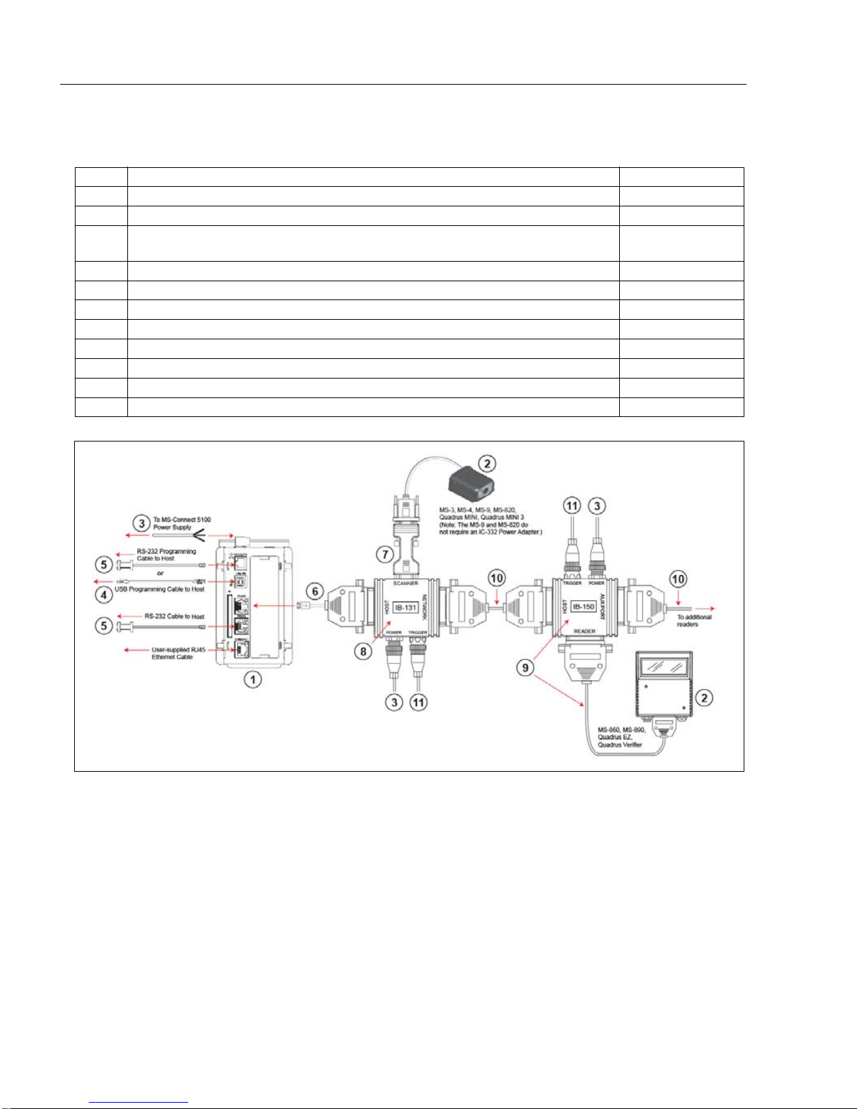
Note: The Multidrop configuration shown above is just one example of configuration options. Any
combination of Microscan readers and interface boxes can be used in the Multidrop network. See
Step 7, Set Up Software, for more specific information about the cabling for each MS-Connect
5100 port.
Multidrop Network Hardware
Step 1 — Check Required Hardware
Item Description Part Number
1 MS-Connect 5100 FIS-5100-0001G
2 Microscan Reader (one per Multidrop address) FIS-XXXX-XXXXG
MS-Connect 5100 Power Supply (24VDC)
3
Reader Power Supply (24 VDC ; on e re quired per reader)
4 Programming Cable, USB, Type A to Type B, 6 ft. 61-000112-01
5 RS-232 Host Cable, 9-pin to RJ12, 6 ft. 61-000108-01
6 MS-Connect 5100 Concentrator Cable, 25-pin to RJ45, 10ft., gender changer 61-000113-01
7 IC-332 Adapter (5-volt readers only) FIS-0001-0035G
8 IB-131 Interface Box 99-000018-01
9
IB-150 Kit, with reader cable, 6 ft.
10 Multidrop Cable, 10 ft. (Gender changer required to connect IB-131 and IB-150) 61-100030-03
11 Object Detector (optional) 99-000017-01
97-100004-15
98-000040-02
1-2 MS-Connect 5100 User’s Manual
Page 10
Setup and Operation
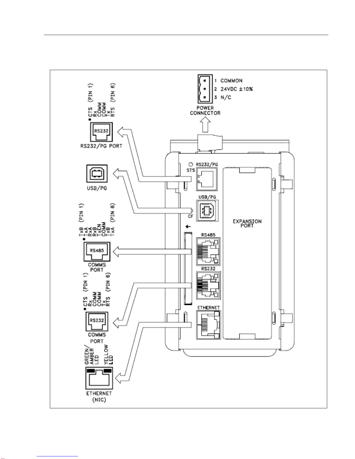
MS-Connect 5100 Port Pinouts
Step 1 — Check Required Hardware (cont.)
MS-Connect 5100 User’s Manual 1-3
Page 11
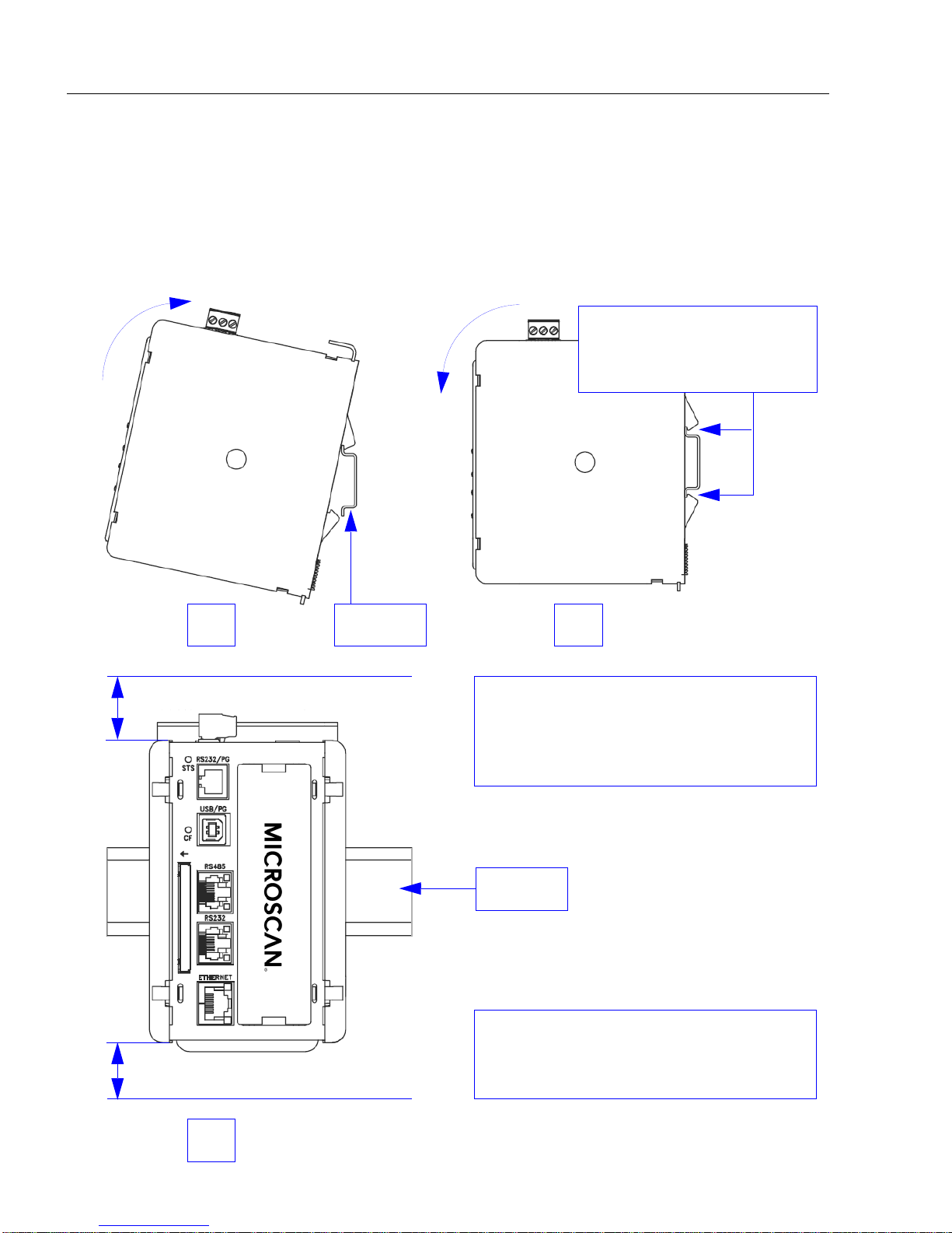
Install the MS-Connect 5100 Unit
1 2
DIN rail
Note: A minimum clearance of 1 inch
(25.4 mm) should be maintained above
and below the unit in order to ensure
proper thermal regulation.
The clamps at the back of
the unit should snap
securely onto the DIN rail.
3
1.00” min. clearance
1.00” min. clearance
DIN rail
1.00” min. clearance
Note: For an alternate m ou nt in g o pt io n,
see Mounting to Flat Surfaces on
page A-8.
Step 2 — Install the MS-Connect 5100 Unit
Mount the MS-Connect 5100 to a DIN Rail
The DIN rail should be positioned horizontally so that the unit’ s ventilation holes are vertical
in relation to cabinet orientation.
Attach the MS-Connect 5100 to the DIN rail as shown below.
1-4 MS-Connect 5100 User’s Manual
Page 12
Setup and Operation
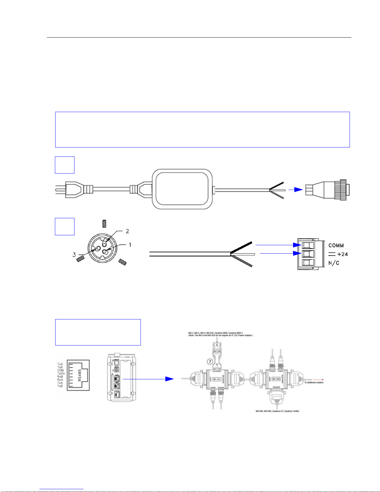
The Microscan power supply (97-100004-15) comes with a standard Micro-Change connector.
You must remove the Micro-Change connector from the end of the cable and wire the cable
directly to the screw terminal block at the top of the unit.
1
2
• Pin 1 = GND (black)
• Pin 2 = Shield
• Pin 3 = +24VDC (white)
1
2
3
Remove the Micro-Change connector and wire-strip the power supply cable.
Use the RS-485 port for
the Multidrop network.
Note: The Multidrop configuration shown above is just one example of configuration
options. Any combination of Microscan readers and interface boxes can be used in the
Multidrop network. See Step 7, Set Up Soft ware, for specific information about the uses of
each MS-Connect 5100 port.
Step 3 — Connect Hardware for Multidrop
Power Connection Wiring
Once the MS-Connect 5100 unit has been physically installed in your application, the
power supply can be wired to the unit.
Multidrop Hardware Configuration
The MS-Connect 5100 can support up to 32 Microscan readers in Multidrop configuration.
Important: All readers must be configured for Multidrop before they can be added to the
Multidrop network.
MS-Connect 5100 User’s Manual 1-5
Page 13

Apply Power to the Multidrop Network
CAUTION: Be sure that all cables are connected BEFORE applying power to the
system. Always power down BEFORE disconnecting any cables.
Step 4 — Apply Pow er to the Multidrop Network
Once you have configured your hardware for Multidrop and securely connected all other
cabling, you can safely apply power to the MS-Connect 5100 and the connected readers.
Important Notes
It is very important that the power supply is mounted correctly if the unit is to opera te reliably.
Please be sure to observe the following points:
• The power supply must be mounted close to the unit, with no more than 6 feet (1.8 m) of
cable between the supply and the unit. Ideally, the shortest length possible should be
used.
• The wire used to connect the unit’s power supply should be at least 22-gauge wire. If a
longer cable run is used, a heavier gauge wire sho uld be u sed. The ro uting of th e cab le
should be kept away from large contactors, inverters, and other devices which may
generate significant electrical interference.
• A power supply with a Class 2 or SELV rating must be used. A Class 2 or SELV power
supply provides isolation to accessible circuits from hazardous volt age leve ls generate d
by a mains power supply due to single faults. SELV is an acronym for “safety extra-low
voltage”. Safety extra-low voltage circui ts shall exhibit vo ltag es safe to touch both under
normal operating conditions and after a single fault, such as a breakdown of a layer of
basic insulation or after the failure of a single component has occurred.
1-6 MS-Connect 5100 User’s Manual
Page 14

Setup and Operation
Step 5 — Install ESP
Easy Setup Program (ESP) is Microscan’s propriet ar y setup and te sting ap plication. The
purpose of ESP is to provide a quick and easy way to set up and configure Microscan
products.
When the MS-Connect 5100 is connected to a host computer (Windows V ist a, XP, or 2000),
ESP can be used to configure Multidrop settings and set up communication with a host.
If installing from the Microscan Tools CD:
1. Insert the Microscan Tools CD in your computer’s CD drive.
2. Select ESP Software from the navigation bar at the left of the screen.
3. Click on ESP Software under the Current Version heading.
4. Click the Run button and follow the prompts in the ESP Setup Wizard.
Note: During installation, you may see an Internet Explorer Security Warning that
states: “The publisher could not be verified.” If you see this warning, click Run to
continue installation.
If downloading from the web:
1. Go to the Download Center at www.microscan.com.
2. Create a new member account or, if you are already a member, enter your user name
and password.
3. Navigate to the “Microscan Software” section of the Download Center (near the top of
the page).
4. Click on the link showing the latest version of ESP. Extract the ESP installation files to
a location of your choice on the host computer. Note where your ESP.exe file is stored
on your hard drive.
5. At the end of the installation process, the following icon will appear on your desktop:
6. Click the ESP icon to start the program.
System Requirements for ESP
• 166 MHz Pentium processor (recommended)
• Windows Vista, XP, or 2000 operating system
• Internet Explorer 5.0 or higher
• 64 MB minimum RAM
• 40 MB minimum disk space
• 800 x 600 pixel minimum 256 color display
MS-Connect 5100 User’s Manual 1-7
Page 15

Install USB Driver
Step 6 — Install USB Driver
When the MS-Connect 5100 is connected to a 24V power supply and the USB programming
cable is connected to the host computer for the first time, you will be prompted to install
the USB driver.
1. When you see the Found New Hardware Wizard, select Install from Specific
Location.
2. Navigate to the ESP-5100\Device folder.
Note: When ESP is installed, the MS-Connect 5100 USB driver is automatically
placed on the host hard drive along with the other ESP installation files.
Example Location: “C:\Program Files\Microscan\ESP-5100\Device”.
3. If the driver is selected, a non-compatibility warning will occur. this warning can be
ignored.
4. After the driver is installed, an extra USB controller is displayed in the hardware
Device Manager.
1-8 MS-Connect 5100 User’s Manual
Page 16
Setup and Operation
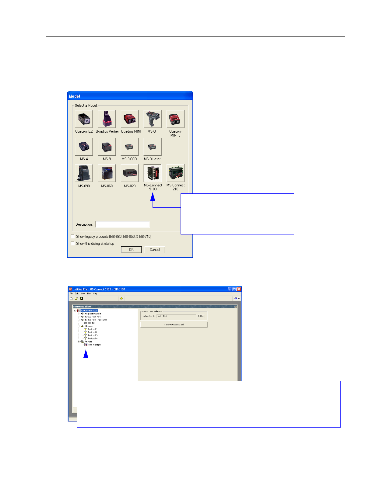
Select the MS-Connect 5100 and
click OK, or simply double-click
the MS-Connect 5100 button to
make your selection.
You will see this window after selecting the MS-Connect 5100.
Important: Each port is shown in the Communications tree control, and must be
configured separately . When you click on the name of a port, that port’s configuration
options will appear to the right of the tree control.
Step 7 — Set Up Software
1. After installing ESP and the USB driver, run the program and select the MS-Connect
5100 from the model menu.
Note: It may take seve ral seconds for the nex t screen to appear if this is the first time
you have selected the MS-Connect 51 00 .
MS-Connect 5100 User’s Manual 1-9
Page 17

Set Up Software
Select the USB
programming
port and click OK.
The Receive function will load the
MS-Connect 5100’s configuration
profile in ESP.
Set Up Software (cont.)
2.
Once the
port. Select USB from the list of options.
ESP
interface has appeared, select
Link > Options
to configure the programming
3. Select Link > Receive and save the configuration file.
1-10 MS-Connect 5100 User’s Manual
Page 18
Setup and Operation
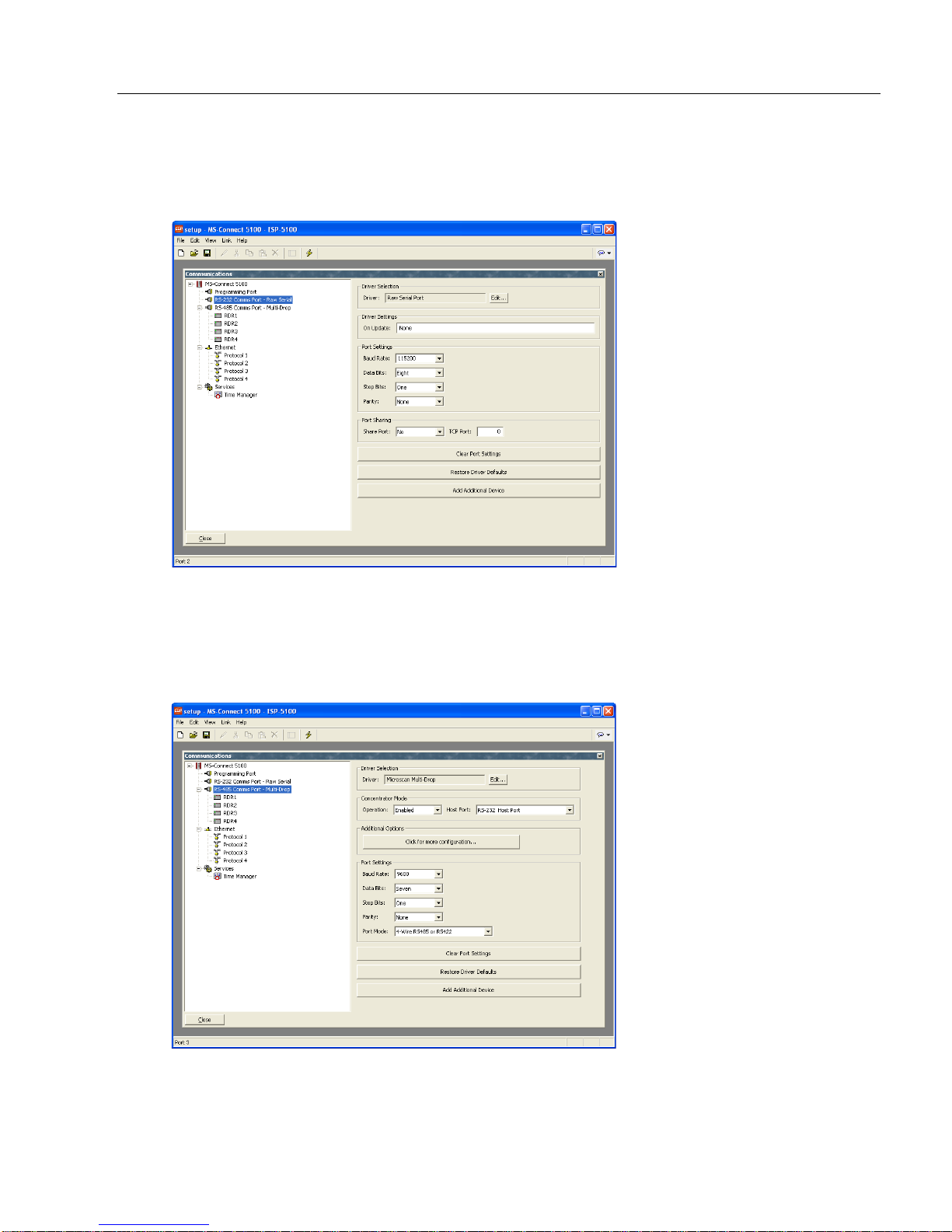
Set Up Software (cont.)
4. Set RS-232 Port Settings as required for communication between the host and the
MS-Connect 5100. Verify that Driver is set to Raw Serial Port.
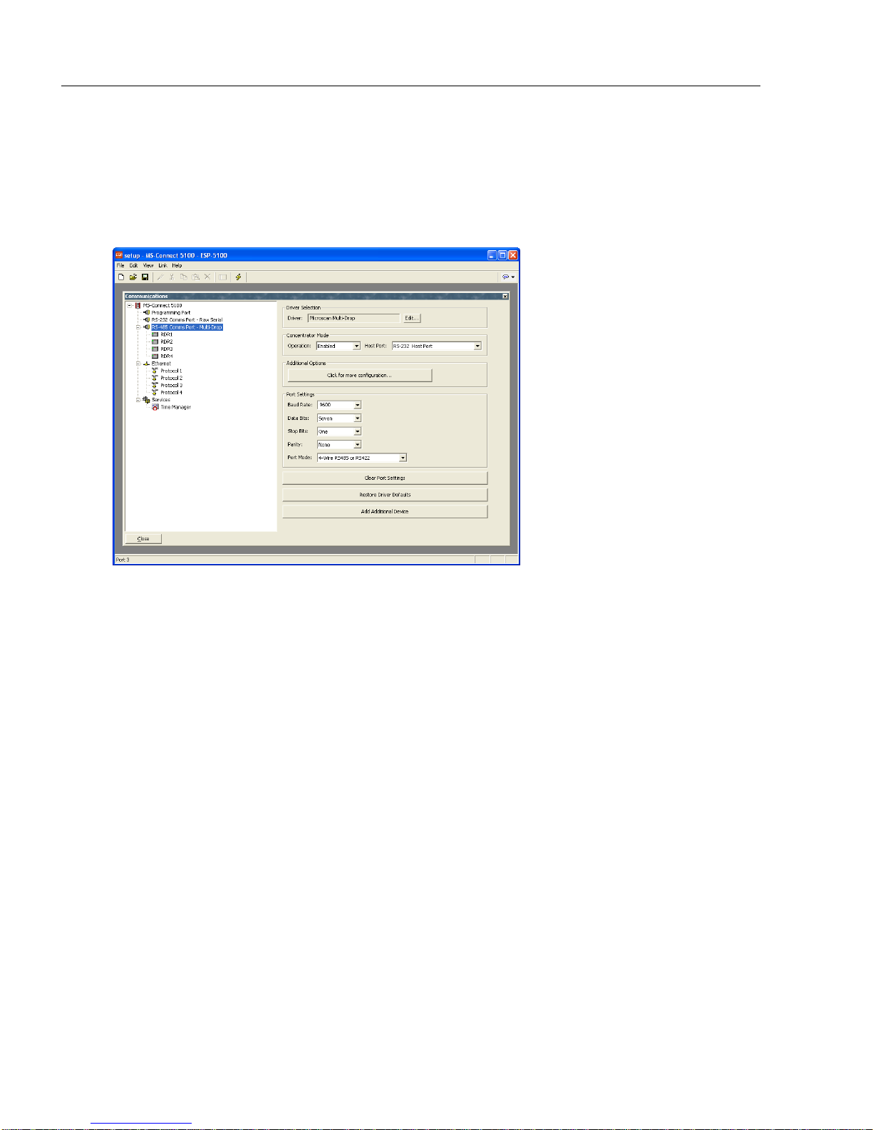
5. Set RS-485 Port Settings to the required connection settings for communication
between the readers in the Multidrop network and the MS-Connect 5100.
Verify that Driver is set to Microscan Multidrop, Concentrator Mode is set to
Enabled, Host Port is set to RS-232 Host Port, and Port Mode is set correctly for the
current application.
MS-Connect 5100 User’s Manual 1-11
Page 19
Set Up Software
Set Up Software (cont.)
6. The reader name and address can be configured in the RS-485 Communications
Port tree.
The MS-Connect 5100 uses address 50. Do not use this address for a reader. Select
the Enable Device check box to enable the device.
The system is now ready for operation.
1-12 MS-Connect 5100 User’s Manual
Page 20
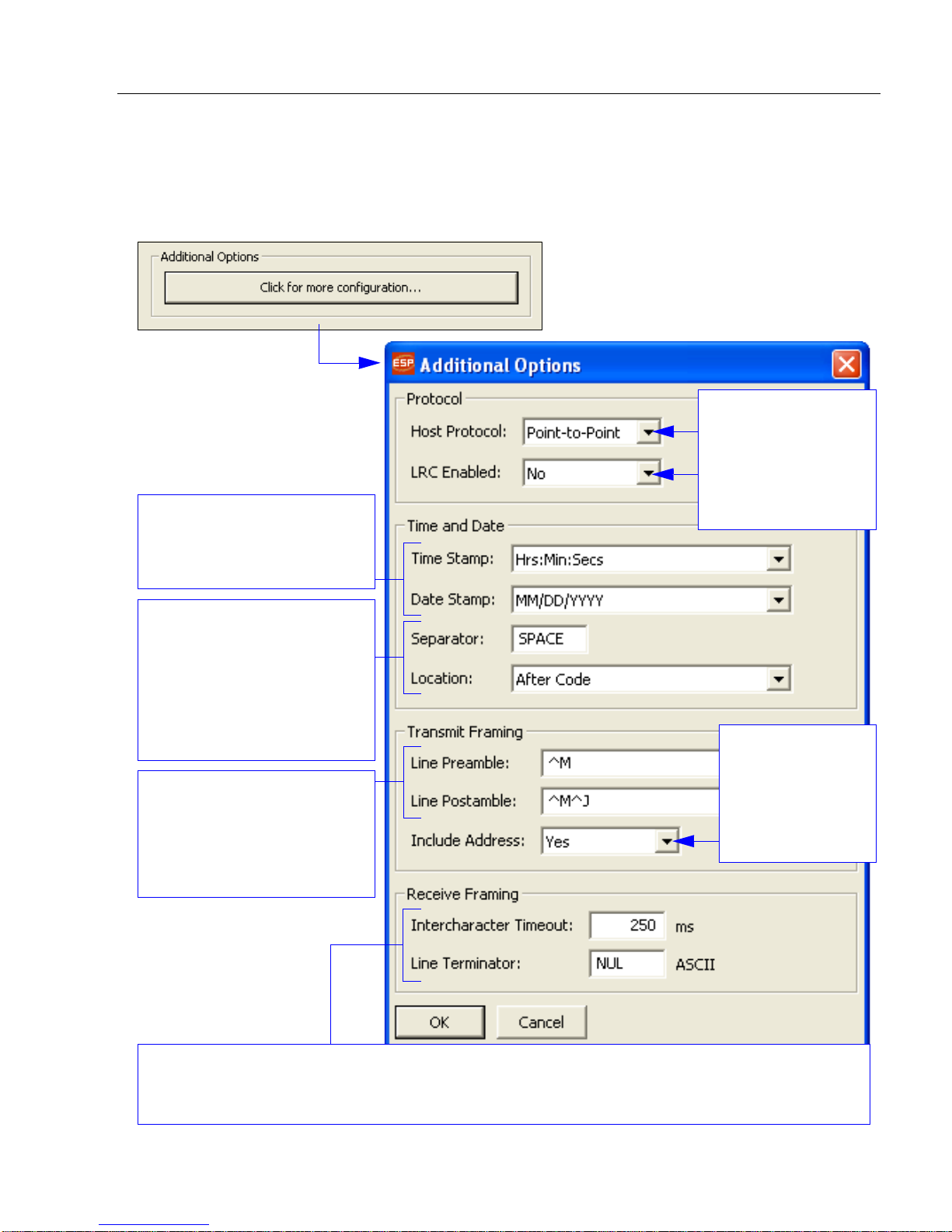
Additional Options
Time Stamp and Date Stamp
allow you to append the time
and date to symbol data that is
decoded and displayed.
Separator lets you determine
the ASCII character that will
separate the time and date
stamps from symbol data.
Location
allows you to determine
whether you want the time and
date stamps to appear before
or after symbol data.
Preamble
and
Postamble
allow
you to set the ASCII character(s)
or control characters (such as
^M
for
Carriage Return
) that will
precede and follow the displayed
symbol data.
Include Address
allows you to
append the
reader’s Multidrop
address to the
beginning of each
reader’s data output.
Host Protocol
defines the type of
connection to the host.
LRC Enabled lets you
turn Longitudinal
Redundancy Check
on or off.
Intercharacter Timeout allows you to set the amount of time that mu st pass bef ore the end of a read cycle.
Line Terminator is the end-of-message character that must be sent at t he e nd o f a message st ream to or
from the MS-Connect 5100 or host device.
For additional RS-485 communications option s, click the Click for more configuration...
button in the Additional Options section of the RS-485 communicat ions vie w. The
Additional Options dialog will appear.
Setup and Operation
MS-Connect 5100 User’s Manual 1-13
Page 21
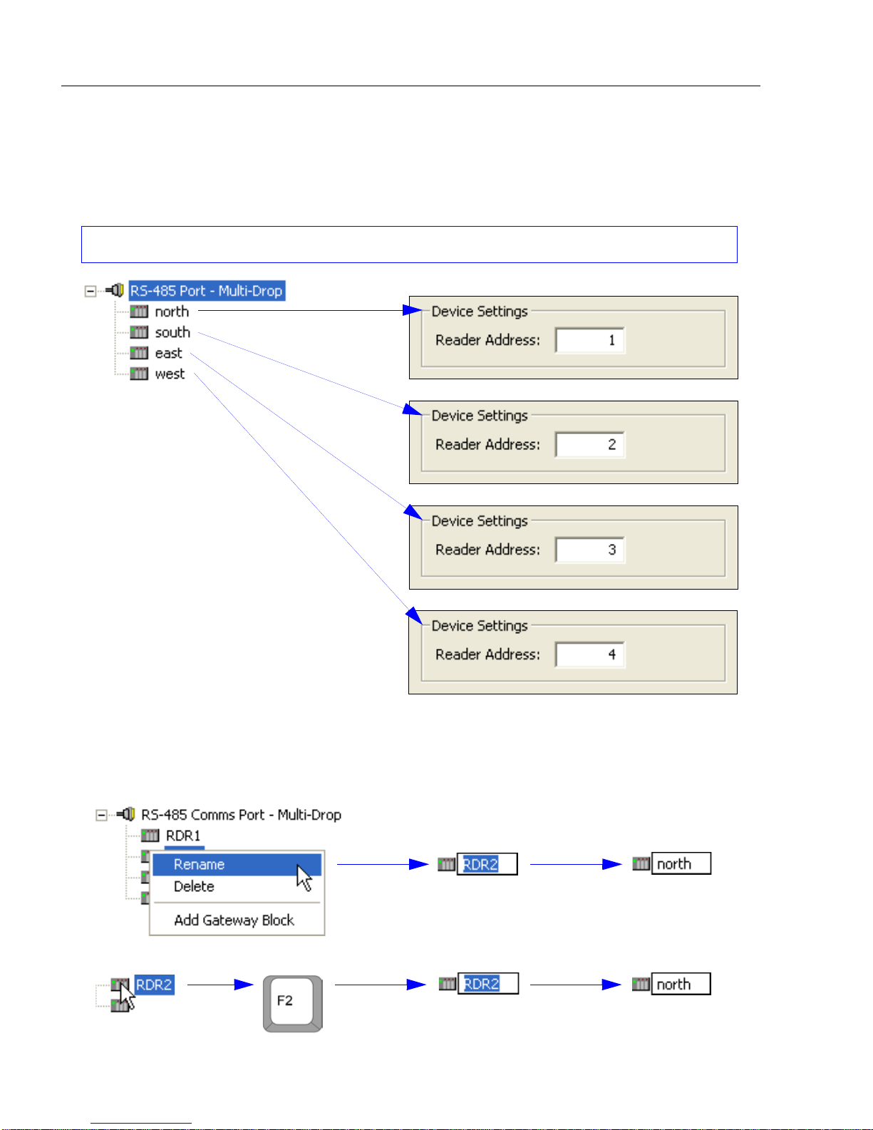
Set Up Software
Each reader must be assigned its own Multidrop address when it is added to the network.
Add Devices
The MS-Connect 5100 supports up to 32 Micro scan readers in a Multidrop network. After
all devices (readers) in the network have been added, you must assign a station number
(Multidrop address) to each.
Renaming a Device
You can rename each device shown in the tree control to reflect specific characteristics of
your application, as in the example shown below. There are two ways to rename a device:
• Right-click the device icon and select Rename, then type the new name.
• Or, select the device and press the F2 key, then type the new name.
1-14 MS-Connect 5100 User’s Manual
Page 22
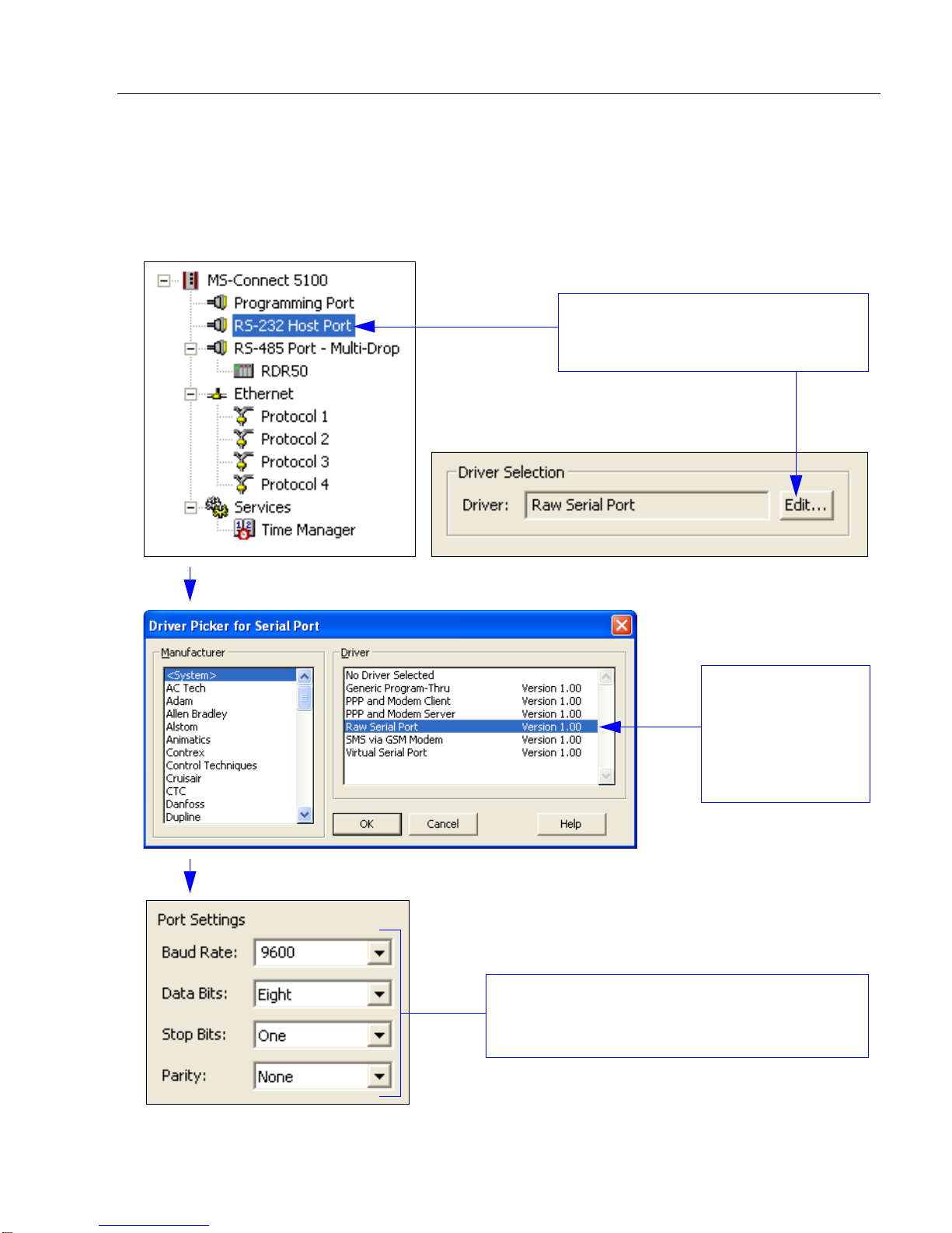
Setup and Operation
Select the RS-232 port in the tree
control, and then click the Edit button
in the Driver Selection dialog.
Select Raw Serial
Port when the
Driver Picker for
Serial Port
appears, and click
OK.
Important: RS-232 Port Settings must match
host settings for baud rate, data bits, stop bits,
and parity.
Host Port Settings
RS-232
You must adjust the RS-232 host port to send polled data in the proper format.
To adjust the RS-2 3 2 host po r t:
MS-Connect 5100 User’s Manual 1-15
Page 23

Set Up Software
Enter the IP Address,
Network Mask, and
Gateway Address.
Select Ethernet in the tree control and then select Port Mode.
Manual Configuration: Port settings are manually configured
as shown below.
DHCP or APIPA: Port settings are configured automatically.
Identify the MS-Connect 5100 by the MAC address.
Select
Raw TCP/IP Active
or
Raw TCP/IP
Passive
to determine how the conne ction
is established.
Note:
In
Active
, the MS-Connect 5100
establishes a connection with the ho st,
and in
Passive
, the host establishes the
connection.
1
2
3
4
Then select one of the Protocol options and click the
Edit button when the Driver Selection dialog appears.
Ethernet TCP/IP
Note:
You must adjust the Ethernet host port to send polled data in the proper format.
To adjust the Ethernet TCP/IP host port:
For an explanation of
EtherNet/IP
, see
EtherNet/IP Overview
in Chapter 2,
Using ESP
.
If you are using Active TCP/IP, enter the IP Address an d TCP/IP Port of the ho st
before saving changes to the MS-Connect 5100.
If you are using Passive TCP/IP, enter the TCP port number where the host will
establish its connection.
1-16 MS-Connect 5100 User’s Manual
Page 24

Setup and Operation
Step 8 — Configure the Reader
Every application is unique, and each Microscan reader has different co nfiguration
requirements. Refer to the user’s manual for the Microscan reader or readers being used
in your application.
Important: All readers must be configured for Multidrop before they can be added to a
Multidrop network.
Reader Setup
1. Start ESP and connect to the rea der. (An MS-3 Laser Scanner is used in the example
below.)
2. In the Read Cycle tree control, set Trigger Mode to Serial Data to test.
3. Set the Serial Trigger Character to T.
4. In La ser Setup, set Laser On/O ff to Enabled to see the beam switch on when the
unit is triggered. (Applicable to laser scanners only.)
MS-Connect 5100 User’s Manual 1-17
Page 25

Configure the Reader
Reader Setup (cont.)
5. In the Communications tree control, disable Preamble and Postamble.
6. Set RS-232/422 Host Port parameters to match the MS-Connect 5100 Multidrop
port.
7. Set Host Protocol to Multidrop.
8. Set the Host Protocol Address of the first reader to 1.
Important: Be sure that each reader in the network has its own unique address.
9. Set Host 422 Status to Enabled.
10. Set LRC Status to Enabled.
11. Send and Save settings. Communications with the reader will be lo st.
Note: ESP may show the communication status as CONNECTED during this interval,
but it is not.
Important: To test the system, you will need to Force Connect using ESP, or use
another terminal program. Use the same connection speed currently set on the MS-Connect
5100’s RS-232 Com Port. The MS-Connect 5100’s RS-232 Port (not the RS-232/PG
Port) must be connected to the host system.
1-18 MS-Connect 5100 User’s Manual
Page 26

Setup and Operation
Step 9 — Test the System
1. Force Connect using ESP, or use another terminal program. Use the same connection
speed currently set on the MS-Connect 5100’s RS-232 Com Port.
2. Connect the MS-Connect 5100 RS-232 Port (not the RS-232/PG Port) to the host
system.
MS-Connect 5100 User’s Manual 1-19
Page 27

Test the System
Test the System (cont.)
3. Create a new macro with entry 01<T>CR. CR can be entered by typing <Ctrl>+m.
4. Trigger the reader by clicking the appropriate macro button.
1-20 MS-Connect 5100 User’s Manual
Page 28

Setup and Operation
Step 10 — Begin Active Operation of Network
Once all ports and devices are configured, you can begin capturing data.
For information about the Microscan p roducts that can be used with the MS-Connect
consult the documentation on your Microscan Tools CD or visit
www.microscan.com
.
5100,
MS-Connect 5100 User’s Manual 1-21
Page 29

Begin Active Operation of Network
1-22 MS-Connect 5100 User’s Manual
Page 30

2 Using ESP
Communications Window.............................................................................................................2-5
Menu Toolbar................................................................................................................................2-6
Configuring Communications.................................................... ... ............................... ... .. ...........2-12
Time Manager.............................................................................................................................2-25
Contents
The MS-Connect 5100 is configured using ESP Software. ESP is available from Microscan’s
website, and on the Microscan Tools CD.
When you configure the MS-Connect 5100 using the latest version of ESP, you are
assured that your unit has the most up-to-date feature set available. ESP software can
configure the MS-Connect 5100 through the USB/PG port and the RS-232/PG port.
MS-Connect 5100 User’s Manual 2-1
Page 31

Communications Window
Note: If you close the Communications
view, the main window will close and the
Communications icon will appear at the
center of the screen. You can return to the
main window by double-clicking the icon.
Communications Window
When the main MS-Connect 5100 ESP view appears, it will look like this:
2-2 MS-Connect 5100 User’s Manual
Page 32

Using ESP
Menu Toolbar
ESP’s Menu Toolbar offers several configuration options in a series of dropdown menus.
File
New
Whenever New is selected, the default configuration of ESP is loaded.
Open / Save
When Save or Save As is selected, the ESP configuration is saved to th e host computer’s
hard drive and available whenever the same file is selected under Open.
MS-Connect 5100 User’s Manual 2-3
Page 33

Menu Toolbar
Open
New
Open
Update
View
Toolbar
When Toolbar is selected, the graphic toolbar is displayed toward the top of the screen.
Status Bar
When Status Bar is selected, the area at the bottom of the screen defines and explains
the function or operation currently in vi ew.
Refresh
The Refresh command refreshes the display, reapplying sorts and filters.
2-4 MS-Connect 5100 User’s Manual
Page 34

Using ESP
Link
Update
When you make new configuration changes, you can use the Update command to activate
those changes in the MS-Connect 5100.
Update sends only the most recently changed configuration parameters to the MS-Connect
5100.
The F9 key can also be used to send the Update command, as well as the Update icon in
the toolbar:
Send
The Send command transfers all current configuration settings to the MS-Connect 5100.
Shift+F9 can also be used to initiate the Send command.
Receive
Receive will load the MS-Connect 5100’s configuration profile in ESP.
Mount Flash
Remote firmware updates over TCP/IP require the MS-Connect 5100 to be fitted with a
CompactFlash card.
Mount Flash
enables Windows Explorer to access the MS-Connect 5100’s CompactFlash card.
Dismount Flash
Remote firmware updates over TCP/IP require the MS-Connect 5100 to be fitted with a
CompactFlash card.
Dismount Flash prevents Windows Explorer from accessing the MS-Connect 5100’s
CompactFlash card.
MS-Connect 5100 User’s Manual 2-5
Page 35

Menu Toolbar
Format Flash
Remote firmware updates over TCP/IP require the MS-Connect 5100 to be fitted with a
CompactFlash card.
Format Flash creates a new file system on the MS-Connect 5100’s CompactFlash card.
Send Time
Send Time sends the host computer’s real-time clock setting to the MS-Connect 5100.
Important: Use the Send Time function to match the time and date in the MS-Connect
5100 with the time and date of the host computer sending commands.
Options
Options brings up a dialog that allows you to select serial, USB, or TCP/IP communication
with the MS-Connect 5100.
2-6 MS-Connect 5100 User’s Manual
Page 36

Help
When context-sensitive Help is enabled for “Mouse Over”,
pop-ups explain the definition and use of objects directly
beneath the cursor.
Contents
Displays ESP’s Help system menu for the MS-Connect 5100.
Technical Support
Displays Microscan’s technical support contact information.
Do Not Display
Using ESP
Disables ESP’s context-sensitive Help pop-ups (“Mouse Over”).
When Mouse Over
Enables ESP’s context-sensitive Help pop-ups, but only when the cursor is pla ced ove r
objects of interest.
When Selected
Enables ESP’s context-sensitive Help pop-ups, but only when objects of interest are
specifically selected.
About...
Displays information about the current version of ESP for the MS-Connect 5100.
MS-Connect 5100 User’s Manual 2-7
Page 37

Configuring Communications
Communications
Tree Control
Configuring Communications
The Communications window lists the MS-Connect 5100’s available ports in the form of
a tree control.
Selecting a Programming Port
The programming link between the host computer and the MS-Connect 5100 is made
using an RS-232 serial port or a USB port. Before downloading configuration profiles, use
the Link Options dialog to select your programming link.
2-8 MS-Connect 5100 User’s Manual
Page 38

Using ESP
Select Microscan from the Manufacturer menu
and Multidrop from the Driver menu, and click OK.
Verifying the USB Programming Link
If you are using the USB programming link, be sur e that the USB drive r has been installed
correctly.
See Install USB Driver for installation instructions.
Downloading Configuration Settings
A configuration profile can be downloaded in it s entirety, or recent changes to settings can
be downloaded individually.
Select Send to download all configuration settings simultaneously.
Select Update to download only the most recently changed configuration settings.
Selecting a Serial COM Port
If you are using the serial programming port (RS-232/PG) as a COM port, it will not be
available for downloading commands. If the serial programming port must be used for
communications, it is highly recommended that you use the USB port for your programming
link. Microscan recommends using the RS-232/PG port for programming only.
Selecting Microscan Multidrop
To select a protocol for a specific COM port, click on that port’s icon in the Communication
window’s tree control, and then click Edit to the right of the Driver text field in the right-hand
pane. The Driver Picker for Serial Port dialog will appear.
MS-Connect 5100 User’s Manual 2-9
Page 39

Configuring Communications
New device
You can add devices to the Multidrop network by clicking the Add
Additional Device button.
Click the desired reader icon to assign and manage reader addresses
in the right pane of the Communications window.
Working with Devices
After you have selected
Microscan Multidrop
, you will see the RS-485 settings shown below .
Notice that a device has been added below the RS-485 Mul tidrop entry in the tree control.
The MS-Connect 5100 can poll up to 32 devices concurrently. ESP allows you to create
more than 32 devices, but no more than 32 should be simultaneously active. Each reader
must be assigned a unique address ranging from 1 to 50.
2-10 MS-Connect 5100 User’s Manual
Page 40

Using ESP
Port Settings
Ethernet Port Configuration
You can navigate to the Ethernet view by clicking on the Ethernet icon in the left-hand
pane of ESP’s Communications window. When this icon is selected, the following view is
displayed:
Port Settings
The Port Mode options determine whether or not the port is enabled, and the method by
which the port is to obtain its IP configuration.
If Manual Configuration (the recommended mode) is selected, the IP Address, Network
Mask, and Gateway fields must be filled out with the appropriate information.
If DHCP or APIPA is selected, the IP address is automatically received from the host. The
MS-Connect 5100 is identified by the MAC address.
Important: Be sure to consult your network administrator when selecting appropriate
values for these fields, and be sure to enter and download these values before connecting
the MS-Connect 5100 to your network. If you fail to do this, it is possible—although
unlikely—that you will cause network problems.
Note: The default values provided for these fields will almost never be suitable for your
application; consult your IT department for appropriate settings.
MS-Connect 5100 User’s Manual 2-11
Page 41

Configuring Communications
IP Routing
IP Routing
The IP Routing option can be used to enable or disable the routing of IP packets between
the Ethernet port and any connections made to or by the MS-Connect 5100. Do no t
enable this option unless you understand the implications of allowing such routing.
2-12 MS-Connect 5100 User’s Manual
Page 42

Using ESP
Physical Layer
Physical Layer
The Physical Layer options control the type of connection that the MS-Connect 5100 will
attempt to negotiate with the hub to which it is connected. Generally, these options can be
left in their default states, but if you have trouble est ablishing a reliable connection, especially
when connecting directly to a PC without an intervening hub or switch, consider turning off
both Full Duplex and High Speed operation to see if this solves the problem.
MS-Connect 5100 User’s Manual 2-13
Page 43

Configuring Communications
Maximum Segment Size
Maximum Segment Size
Maximum Segment Size is the maximum length of the data packet that is sent or
received. This value can be user-defined in the For Send and For Receive fields shown
below.
The minimum value that can be entered in both fields is 64 and the maximum value is 2048.
2-14 MS-Connect 5100 User’s Manual
Page 44

Using ESP
Remote Update
Remote Update
The Remote Update option is used to enable or disable firmware and configuration
download via TCP/IP. As noted in the Link section, remote firmware updates over TCP/IP
require the MS-Connect 5100 to be fitted with a CompactFlash card. Since downloads will
more than likely involve a firmware update at some point, such a card is highly recommended
when using this feature.
Important: IP Download
must be enabled to use the Ethernet port as the programming port.
Note: If you are using RS-232 or Ethernet TCP/IP for Multidrop configuratio n or host
communications, see Configuring Communications on page 2-12.
MS-Connect 5100 User’s Manual 2-15
Page 45

Configuring Communications
Select a
Host Port
and click the
Edit
button next to the
Driver
Selection
dialog in the right-hand pane.
EtherNet/IP Overview
This section explains how to use the MS-Connect 5100 for EtherNet/IP.
1. Select the appropriate Host Port (serial port or Ethernet) for protocol conversion.
2. Select the manufacturer of your device and the appropriate driver (in this e xamp le,
the manufacturer is EtherNet/IP and the driver is TCP/IP Slave).
3. Selecting a driver will create a PLC in the appropriate location on the Communications
menu in the left-hand pane, a s sh o wn b elow.
2-16 MS-Connect 5100 User’s Manual
Page 46

Using ESP
EtherNet/IP Overview (cont.)
4. Create a Gateway Block on the PLC by clicking the Add Gateway Blo ck button.
MS-Connect 5100 User’s Manual 2-17
Page 47

Configuring Communications
Select the start address at which the mapping block will begin.
Once the block size has also been configured, you will be able
to select various data items to be written to or read from the
block. These items may be tags from within ESP or registers
from other devices. For a master device, ESP will read or write
data as required. For a slave device, it will process reads and
writes, either writing to the appropriate destinations or replying
with the selected data.
Select the number
of registers in the
mapping block.
Select the direction of data transfer. For master devices, this controls the
type of operation that ESP will perform. For slave devices, it indicates
whether or not ESP will accept write operations. Slave read operations
are accepted regardless of this setting.
EtherNet/IP Overview (cont.)
5. Click on the Block icon in the Communications tree in the left-hand pane to display
Block Settings in the right-hand pane.
2-18 MS-Connect 5100 User’s Manual
Page 48

Using ESP
EtherNet/IP Overview (cont.)
6. Click Edit in the Start Address row to display Data Items, Data Types, and Elements.
7. Select the appropriate Data Item, Data Type, and Element.
Important: The Element value in this example corresponds to the starting address.
MS-Connect 5100 User’s Manual 2-19
Page 49

Configuring Communications
Individual Registers on Block 1
(left-hand pane)
EtherNet/IP Overview (cont.)
8. Click Edit in the Block Size row to set block size.
Important: The Block Size determines how many registers will appear on the gateway
block.
Entries appear in the left-hand pane of the window to represent each of the registers that
the block exposes to remote access.
In the example below, Block 1 has 10 registers exposed to remote access.
2-20 MS-Connect 5100 User’s Manual
Page 50

EtherNet/IP Overview (cont.)
9. Click Edit in the Direction row to set the direction of data.
Using ESP
MS-Connect 5100 User’s Manual 2-21
Page 51

Configuring Communications
Available Mappings for Block 1
(right-hand pane)
When a register is selected, the
right-hand pane shows a list of
available data items, comprising
both tags from within your database
and data registers from any master
communications devices that you
have configured.
Note: Use Command Code for
sending serial commands.
EtherNet/IP Overview (cont.)
10. Map individual registers.
2-22 MS-Connect 5100 User’s Manual
Page 52

Using ESP
Left-click on the desired Data
Item in the right-hand pane.
Drag the Data Item directl y
over its corresponding
gateway block register.
EtherNet/IP Overview (cont.)
To indicate that you want a particular register within your gateway block to correspond to a
particular data item, simply drag that item from the right-hand pane to the left-hand pane,
dropping it on the appropriate register entry.
MS-Connect 5100 User’s Manual 2-23
Page 53

Configuring Communications
Expansion Port
Note that the drivers
available for a port
will depend on the
connection type it
supports.
Advanced Communications
This section explains how to use some of the more advanced communications features
supported by ESP.
Option Cards
The MS-Connect 5100 is capable of hosting a Profibus expansion card to provide additional
communications facilities.
Hardware installation instructions are provided with Profibus cards.
Selecting the appropriate card will add a corresponding icon to the tree control in the left-hand
pane of the Communications window. Clicking on this icon will contain configuration
optio ns fo r features that are mad e av aila b l e by the card.
The example below shows configuration options for an MS-Connect 5100 with a Profibus
option card installed.
2-24 MS-Connect 5100 User’s Manual
Page 54

Using ESP
Once you have enabled time management,
you must download the correct time zone to
the MS-Connect 5100’s using Link > Send
Time in ESP’s menu toolbar.
Enabling SNTP (Simple
Network Time Protocol)
for Time Server allows
other Microscan products
to sync their clocks to the
MS-Connect 5100’s clock.
Enabling Linked
DST syncs the
MS-Connect
5100’s Daylight
Savings Time
setting to the one
on the server.
Enabling
SNTP
for
Time Client
syncs the MS-Connect 5100’s
clock to another Microscan
product’s clock or another
SNTP time source, such as the
time server on your network.
SNTP Mode determines how the SNTP client
should be configured.
Enter the IP address of the SNTP server to be
contacted in the SNTP Server field.
Time Manager
Enabling Time Manager allows you to synchronize the MS-Connect 5 100’ s clock with the
network and with other Microscan products.
To access time management settings, click on Time Manager in the Communications
tree control.
MS-Connect 5100 User’s Manual 2-25
Page 55

Time Manager
2-26 MS-Connect 5100 User’s Manual
Page 56

Contents
Appendix A General Specifications..............................................................................................A-2
Appendix B EMI Installation Guidelines .......................................................................................A-3
Appendix C Interface Standards ..................................................................................................A-4
Appendix D Indicator LEDs..........................................................................................................A-5
Appendix E CompactFlash Card..................................................................................................A-6
Appendix F Mounting Options......................................................................................................A-7
Appendix G Multidrop Communications.......................................................................................A-9
Appendix H ASCII Table ............................................................................................................A-13
Appendix I Protocol Command Table.........................................................................................A-14
Appendix J Glossary of Terms...................................................................................................A-15
Appendices
MS-Connect 5100 User’s Manual A-1
Page 57

General Specifications
MS-Connect 5100 Dimensions
Front
Side
Appendix A — General Specifications
Mechanical
Mounting: Snaps onto standard DIN style top hat (T) profile mounting
rails per EN 50022 -35 x 7.5 and -35 x 15
Width: 3.09” (78.5 mm)
Height: 5.3” (134.7 mm)
Weight: 15.1 oz. (456.4 g)
Environmental
Enclosure: IP65
Operating Tempurature: 0° to 50°C
Storage Tempurature: -30° to +70°C
Operating and Storage Humidity:
from 0 to 50°C
Vibration According to IEC 68-2-6: 5 to 150 Hz, in X, Y , Z direction for
1.5 hours, 2 g
Shock According to IEC 68-2-27:
Altitude: Up to 2000 meters
Electrical
Power Supply: 24VDC ± 10%
200 mA min., without expansion card
1 Amp max. with expansion card fitted
Must use Class 2 or SELV rated power supply
Power Connector: Removable wire clamp screw terminal block
Wire Gauge Capacity: 24 AWG to 12 AWG
Torque: 4.45 to 5.34 in./lb. (0.5 to 0.6 N-m)
Indicator LEDs
STS: Status LED indicates condition of unit
TX/RX: Transmit/Receive LEDs show serial activity
Ethernet: Link and activity LEDs
CF: CompactFlash LED indicates card status and read/write activity
Memory
Onboard User Memory: 4 MB of non-volatile flash memory
Onboard SDRAM: DSPSX: 2 MB; DSPGT: 8 MB
Memory Card: CompactFlash Type II slot for Type I and Type II cards
Real-Time Clock
Typical accuracy is less than one minute per month drift. ESP-5100’s SNTP facility allows synchronization with
external servers
Battery: Lithium Coin Cell. Typical lifetime of 10 years at 25 ºC
A “Battery Low” system variable is available so that the programmer can choose specific action(s) to occur when
the battery voltage drops below its nominal voltage
Communications
Standard Interfaces: USB/PG (programming), RS-232/PG (programming), RS-232 via RJ12, RS-485 via RJ45,
Ethernet via RJ45, wired to Network Interface Card
Safety Certifications
UL/cUL, CE
ISO 9001:2000 Certification No. 06-1080
Issued by TüV USA
80% max. relative humidity , non-condensing,
Operational 30 g, 1 1 msec in 3 directions
©2007 Microscan Systems, Inc.
All rights reserved. Specifications subject to change.
Warranty–One year limited warranty on parts and labor. Extended warranty available.
A-2 MS-Connect 5100 User’s Manual
Page 58

Appendices
Appendix B — EMI Installation Guidelines
Although this product is designed with a high degree of im munity to Electro magnetic
Interference (EMI), proper installation and wiring methods must be followed to ensure
compatibility in each application. The type of the electrical noise, source or coupling
method into a unit may be different for various installations. Cable length, routing, and
shield termination are very important and can mean the difference between a successful
or unsuccessful installation. Listed are some EMI guidelines for a successful installation
in an industrial environment.
1. To reduce the chance of noise spikes entering the unit via the power lines, connections
should be made to a clean source. Connecting to circuits that also power loads such
as contactors, relays, motors, solenoids, etc., should be avoided.
2. The unit should be mounted in a metal enclosure, which is properly connected to
protective earth.
3. Use shielded (screened) cables for all Signal and Control inputs. The shield (screen)
pigtail connection should be made as short as possible. The connection point for the
shield depends somewhat upon the application. Listed below are the recommended
methods of connecting the shield, in order of their effectiveness.
a. Connect the shield to earth ground (protective earth) at one end where the unit is
mounted.
b. Connect the shield to earth ground at both ends of the cable, usually when the
noise source frequency is over 1 MHz.
c. Connect the shield to common of the MS-Connect 5100 and leave the other end of
the shield unconnected and insulated from earth ground.
4. Never run Signal or Control cables in the same conduit or raceway with AC power
lines, conductors feeding motors, solenoids, SCR controls, heaters, etc. The cables
should be run through metal conduit that is properly g rounded. T his is especially
useful in applications where cable runs are long and portable two-way radios are used
in close proximity or if the installation is near a commercial radio transmitter. Also,
Signal or Control cables within an enclosure should be routed as far away as possible
from contactors, control relays, transformers, and other noisy components.
5. Long cable runs are more susceptible to EMI p ickup than sho rt cable runs. Th erefore,
keep cable runs as short as possible.
6. In extremely high EMI environments, the use of external EMI suppression devices is
effective. The following EMI suppression devices (or equivalent) are recommended:
Ferrite Suppression Cores for signal and control cables:
Fair-Rite part number 0443167251
TDK part number ZCAT3035-1330A
Steward part number 28B2029-0A0
Line Filters for input power cables:
Schaffner part number FN610-1/07
Schaffner part number FN670-1.8/07
Corcom part number 1 VR3
MS-Connect 5100 User’s Manual A-3
Page 59

Interface Standards
RS-485 4-Wire Connections
RS-485 2-Wire Connections
Appendix C — Interface Standards
USB/PG Port: Adheres to USB specification 1.1. Device only using Type B connection.
RS-232 Host and RS-232/PG Serial Ports: Format and baud rates for each port are
individually software-programmable up to 115,200 baud. Both serial ports via RJ12.
Only the RS-232/PG port can be used for programming, but both can be used for c ommunications
with a PLC. The RS-232/PG port can be used for master or slave protocols.
RS-485 Port: RS-485 port via RJ45.
Ethernet Port:
When wiring to a hub or switch, use a straight-through cable, but when connecting to
another NIC, use a crossover cable.
10 BASE-T / 100 BASE-TX RJ45 jack is wired to NIC (Network Interface Card).
A-4 MS-Connect 5100 User’s Manual
Page 60

Appendices
Appendix D — Indicator LEDs
STS — Status LED
The green status LED provides information regarding the state of the MS-Connect 5100.
This includes indication of the various stages of the startup routine (power-up), and any
errors that may occur.
LED Indication
Rapidly Flashing
Steady MS-Connect 5100 is operating properly.
User Communication Ports — Tx / Rx LEDs
LED Indication
GREEN Transmitting
RED Receiving
Note: LEDs are not available for the RS-232/PG port.
MS-Connect 5100 is currently running the boot loader and/or being
flash-upgraded by ESP.
Ethernet LEDs
LED Indication
YELLOW (Solid) Link Established
YELLOW (Flashing) Network Activity
GREEN 10 BASE-T Communications
AMBER 100 BASE-TX Communications
CF — CompactFlash LED
LED Indication
Off No CompactFlash card is present.
Steady Valid CompactFlash card is present.
Flashing Rapidly CompactFlash card is being checked.
Unit is writing to the CompactFlash, either because it is storing
Flickering
Flashing Slowly Incorrectly formatted CompactFlash card present.
1. Do not turn off power to the unit while this LED is flickering. The unit writes data in two-minute intervals.
Later Microsoft operating systems will not lock the drive unless they need to write data.
data, or because the PC connected via the USB port has locked
the drive.
1
MS-Connect 5100 User’s Manual A-5
Page 61

CompactFlash Card
Note: For reliable operation, Microscan recommends the use of SanDisk
®
and SimpleTech
brands of CompactFlash cards.
Insert the CompactFlash card
with the top side facing left.
Important: Do not remove or
insert the CompactFlash card
while power is applied to the unit.
Appendix E — CompactFlash® Card
The MS-Connect 5100’s CompactFlash Type II socket can be used for troubleshooting
and configuration transfers. The socket can accept either Type I or Type II cards, which
are available at most computer and office supply retailers. Microscan recommends using
cards with a minimum of 4MB of memory.
Information stored on a CompactFlash card can be read by a card reader attached to a
PC. This information is stored in Windows PC-compatible FAT16 file format.
A-6 MS-Connect 5100 User’s Manual
Page 62

Appendices
1 2DIN rail
Note: A minimum clearance of 1 inch
(25.4 mm) should be maintained above
and below the unit in order to ensure
proper thermal regulation.
The clamps at the back of
the unit should snap
securely onto the DIN rail.
1.00” min. clearance
1.00” min. clearance
DIN rail
3
Appendix F — Mounting Options
DIN Rail Mounting
The DIN rail should be positioned horizontally so that the unit’ s ventilation holes are vertical
in relation to cabinet orientation.
Attach the MS-Connect 5100 to the DIN rail as shown below.
MS-Connect 5100 User’s Manual A-7
Page 63

Mounting Options
Note: A minimum clearance of 1 inch (25.4 mm) should be maintained above and below the
unit in order to ensure proper thermal regulation.
MS-Connect 5100
The mounting bracket is angled so that the MS-Connect 5100 can be
mounted to a vertical or horizont al surface with screws or other fasteners
without changing the unit’s orientation.
Side View
The clamps at the back of the unit should snap securely onto the rail portion of the mounting
bracket, as shown in the illustration.
Mounting to Flat Surfaces
Microscan offers a mounting bracket (10-000251-01) for applications in which the MS-Connect
5100 must be affixed to flat surfaces.
The bracket is angled in such a way that the unit can be mounted to vertical or horizontal
flat surfaces.
A-8 MS-Connect 5100 User’s Manual
Page 64

Appendices
Appendix G — Multidrop Communications
Polling Mode Data Flow Examples
Setup 1
Address 0x01 (translates to) Poll Req @ ‘0x1C’, Unit Select @ ‘0x1D’
RES 0x04
REQ 0x05
STX 0x02
ETX 0x03
ACK 0x06
NAK 0x15
LRC disabled
Transfer 1
HOST_TX ‘RES’ ‘0x1D’ ‘REQ’ (Select Unit 1 to receive data)
IMAGER_TX ‘0x1D’ ‘ACK’ (Unit responds with its address)
HOST_TX ‘STX’ <T> ‘ETX’
IMAGER_TX ‘0x1D’ ‘ACK’ (Unit responds with its address)
HOST_TX ‘RES’ (Terminate Transfer 2)
Transfer 2
HOST_TX ‘RES’ ‘0x1C’ ‘REQ’ (Poll Unit 1 for data)
IMAGER_TX ‘0x1C’ ‘STX’ <T/00000> ‘ETX’
HOST_TX ‘ACK’
IMAGER_TX ‘RES’ (Terminate Transfer 1)
Starting with a ‘RES’ ensures a clean transaction, without “leftovers” from the previous
transaction.
Error Condition 1
HOST_TX ‘RES’ ‘0x1C’ ‘REQ’ (Poll Unit 1 for data)
IMAGER_TX ‘0x1C’ ‘STX’ <T/00000> ‘ETX’
HOST_TX ‘Nothing’ (Host should ‘ACK’ here)
timeout reached...
IMAGER_TX ‘REQ’ (Unit requests an ‘ACK’ again)
timeout reached...
IMAGER_TX ‘REQ’ (Unit requests an ‘ACK’ again)
timeout reached...
IMAGER_TX ‘REQ’ (Unit requests an ‘ACK’ again)
timeout reached...
IMAGER_TX ‘RES’ (Terminate Transfer 1, data is flushed)
MS-Connect 5100 User’s Manual A-9
Page 65

Multidrop Communications
Error Condition 2
HOST_TX ‘RES’ ‘0x1C’ ‘REQ’ (Poll Unit 1 for data)
IMAGER_TX ‘0x1C’ ‘STX’ <T/00000> ‘ETX’
HOST_TX ‘Nothing’ (Host should ‘ACK’ here)
timeout reached...
IMAGER_TX ‘REQ’ (Unit requests an ‘ACK’ again)
HOST_TX ‘NAK’ (Host rejects data frame)
(Retry Event)
IMAGER_TX ‘0x1C’ ‘STX’ <T/00000> ‘ETX’ (Unit sends again)
HOST_TX ‘ACK’ (Host receives data)
IMAGER_TX ‘RES’ (Terminate Transfer 1)
The protocol makes 3 retry attempts before data is flushed and transfer is aborted.
A-10 MS-Connect 5100 User’s Manual
Page 66

Setup 2
Address 0x01 (translates to) Poll Req @ ‘0x1C’, Unit Select @ ‘0x1D’
RES 0x04
REQ 0x05
STX 0x02
ETX 0x03
ACK 0x06
NAK 0x15
LRC enabled
Transfer 1
HOST_TX ‘RES’ ‘0x1D’ ‘REQ’ (Select Unit 1 to receive data)
IMAGER_TX ‘0x1D’ ‘ACK’ (Unit responds with its address)
HOST_TX ‘STX’ <T> ‘ETX’ ‘LRC’
IMAGER_TX ‘0x1D’ ‘ACK’ (Unit responds with its address)
HOST_TX ‘RES’ (Terminate Transfer 2)
Transfer 2
Appendices
HOST_TX ‘RES’ ‘0x1C’ ‘REQ’ (Poll Unit 1 for data)
IMAGER_TX ‘0x1C’ ‘STX’ <T/00000> ‘ETX’ ‘LRC’
IMAGER_TX ‘ACK’
HOST_TX ‘RES’ (Terminate Transfer 1)
Starting with a ‘RES’ ensures a clean transaction, without “leftovers” from the previous
transaction.
Error Condition 1
HOST_TX ‘RES’ ‘0x1C’ ‘REQ’ (Poll Unit 1 for data)
IMAGER_TX ‘0x1C’ ‘STX’ <T/00000> ‘ETX’ ‘LRC’
HOST_TX ‘Nothing’ (Host should ‘ACK’ here)
timeout reached...
IMAGER_TX ‘REQ’ (Unit requests an ‘ACK’ again)
timeout reached...
IMAGER_TX ‘REQ’ (Unit requests an ‘ACK’ again)
timeout reached...
IMAGER_TX ‘REQ’ (Unit requests an ‘ACK’ again)
timeout reached...
IMAGER_TX ‘RES’ (Terminate Transfer 1, data is flushed)
MS-Connect 5100 User’s Manual A-11
Page 67

Multidrop Communications
Error Condition 2
HOST_TX ‘RES’ ‘0x1C’ ‘REQ’ (Poll Unit 1 for data)
IMAGER_TX ‘0x1C’ ‘STX’ <T/00000> ‘ETX’ ‘LRC’
HOST_TX ‘Nothing’ (Host should ‘ACK’ here)
timeout reached...
IMAGER_TX ‘REQ’ (Unit requests an ‘ACK’ again)
HOST_TX ‘NAK’ (Host rejects data frame)
(Retry Event)
IMAGER_TX ‘0x1C’ ‘STX’ <T/00000> ‘ETX’ ‘LRC’ (Unit sends again)
HOST_TX ‘ACK’ (Host receives data)
IMAGER_TX ‘RES’ (Terminate Transfer 1)
Error Condition 3
HOST_TX ‘RES’ ‘0x1C’ ‘REQ’ (Poll Unit 1 for data)
IMAGER_TX ‘0x1C’ ‘STX’ <T/00000> ‘ETX’ ‘BAD LRC’
HOST_TX ‘NAK’ (Host rejects bad LRC data)
(Retry Event)
IMAGER_TX ‘0x1C’ ‘STX’ <T/00000> ‘ETX’ ‘GOOD LRC’ (Unit sends again)
HOST_TX ‘ACK’ (Host receives data)
IMAGER_TX ‘RES’ Terminate Transfer 1)
The protocol makes 3 retry attempts before data is flushed and transfer is aborted.
A-12 MS-Connect 5100 User’s Manual
Page 68

Appendices
Appendix H — ASCII Table
Dec Hex Mne Ctrl Dec Hex Ch Dec Hex Ch Dec Hex Ch
00 00 NUL ^@ 32 20 SP 64 40 @ 96 60 `
01 01 SOH ^A 33 21 ! 65 41 A 97 61 a
02 02 STX ^B 34 22 “ 66 42 B 98 62 b
03 03 ETX ^C 35 23 # 67 43 C 99 63 c
04 04 EOT ^D 36 24 $ 68 44 D 100 64 d
05 05 ENQ ^E 37 25 % 69 45 E 101 65 e
06 06 ACK ^F 38 26 & 70 46 F 102 66 f
07 07 BEL ^G 39 27 ' 71 47 G 103 67 g
08 08 BS ^H 40 28 ( 72 48 H 104 68 h
09 09 HT ^I 41 29 ) 73 49 I 105 69 i
10 0A LF ^J 42 2A * 74 4A J 106 6A j
11 0B VT ^K 43 2B + 75 4B K 107 6B k
12 0C FF ^L 44 2C , 76 4C L 108 6C l
13 0D CR ^M 45 2D - 77 4D M 109 6D m
14 0E SO ^N 46 2E . 78 4E N 110 6E n
15 0F SI ^O 47 2F / 79 4F O 111 6F o
16 10 DLE ^P 48 30 0 80 50 P 112 70 p
17 11 DC1 ^Q 49 31 1 81 51 Q 113 71 q
18 12 DC2 ^R 50 32 2 82 52 R 114 72 r
19 13 DC3 ^S 51 33 3 83 53 S 115 73 s
20 14 DC4 ^T 52 34 4 84 54 T 116 74 t
21 15 NAK ^U 53 35 5 85 55 U 117 75 u
22 16 SYN ^V 54 36 6 86 56 V 118 76 v
23 17 ETB ^W 55 37 7 87 57 W 119 77 w
24 18 CAN ^X 56 38 8 88 58 X 120 78 x
25 19 EM ^Y 57 39 9 89 59 Y 121 79 y
26 1A SUB ^Z 58 3A : 90 5A Z 122 7A z
27 1B ESC ^[ 59 3B ; 91 5B [ 123 7B {
28 1C FS ^\ 60 3C < 92 5C \ 124 7C |
29 1D GS ^] 61 3D = 93 5D ] 125 7D }
30 1E RS ^^ 62 3E > 94 5E ^ 126 7E ~
31 1F US ^_ 63 3F ? 95 5F _ 127 7F D
MS-Connect 5100 User’s Manual A-13
Page 69

Protocol Command Table
Appendix I — Protocol Command Table
Protocol Command
(Mnemonic displayed on menu)
RES ^D 04 Reset
REQ ^E 05 Request
EOT ^D 04 Reset
STX ^B 02 Start of Text
ETX ^C 03 End of Text
ACK ^F 06 Acknowledge
NAK ^U 15 Negative Acknowledge
XON ^Q 11 Begin Transmission
XOFF ^S 13 Stop Transmission
Control Characters
(Entered in menu or
serial command)
Hex
Value
Effect of Command
A-14 MS-Connect 5100 User’s Manual
Page 70

Appendices
Appendix J — Glossary of Terms
Baud Rate — The number of discrete signal events per second. Bits per second.
Connector
for various circuits and pins.
Data Bits — The number of bits used to represent one character of da ta output.
Decode — A Good Read. The successful capture and output of the information encoded
in a symbol.
Discrete I/O — Inputs and output s characterized by discrete signal transitions from one
voltage level to another so that digital switching can occur.
Firmware — Software hard-coded in non-volatile memory.
Good Read — A decode. The successful capture and output of the information encoded
in a symbol.
Host — A computer, PLC (Programmable Logic Controller), or other device that is used to
execute commands and to process data and discrete signals.
Input — A channel or communications line. The decoded data or discrete signal that is
received by a device.
LED (Light-Emitting Di ode) — Often used as a performance indicator, as on the exterior of
the MS-Connect 5100.
LRC (Longitudinal Redundancy Check) — An error checking routine that verifies the
accuracy of transmissions.
Master Symbol — A symbol whose data is stored in a reader and com pared to other
symbols in an application as they are decoded. Useful in applications that require sortation
and routing.
Matchcode — A method of comparing current decoded symbol data against stored
master symbol data. Useful in applications that require sortation and routing.
Micro-Change — A threaded, sealed connector that provides secure cabling in industrial
and automation environments.
New Master — A condition in which a reader decodes and stores a new master symbol in
an application using matchcode.
No Read — A condition in which a reader fails to decode a candidate symbol.
Normally Closed — A discrete output state that is only active when open.
Normally Open — A discrete output state that is only active when closed.
Opto-isolation
and receiver) while keeping the elements electrically isolated. An example of opto-isolation
the relationship of an LED and a light sensor, separated from each other so that light can
travel across a barrier but electrical current cannot.
Output
or displayed by a device.
Parity — An error detection routine in which one dat a bit in each character is set to 1 or 0
so that the total number of 1s in the data field is even or odd.
— Physical device (plug or socket) on a device or cable to provide in/out connectivity
— The transfer of signals between elements of a circuit (typically a transmitter
— A channel or communications line. The data or discrete signals that are transmitted
is
MS-Connect 5100 User’s Manual A-15
Page 71

Glossary of Terms
Port — Logic circuit for receiving and transmitting data. (One or more ports may be
included within a single connector.)
Protocol — The rules for communication between devices, providing a means to control
the orderly flow of information between linked devices.
Read Cycle — A pre-defined period of time during which a reader will attempt to capture
symbol data.
RoHS (Reduction of Hazardous Substances) — A directive that restricts the use of lead,
mercury , cadmium, hexavalent chromium, polybrominated biphenyls (PBB), and polybrominated
diphenyl ether (PBDE) in the manufacture of certain types of electronic and electrical
equipment.
Signal — A transmission of analog or digital information, electrical current, voltage, or
another specific quantity, that can be varied in such a way that it conveys information from
one point to another.
Symbology — A symbol type, such as Code 39 or Code 128, with special rules to define
the widths and positions of bars (or 2D modules) a nd space s to represent specific numeric
or alphanumeric information.
Trigger — A signal, transition, or character string that initiates a read cycle.
WEEE
(Waste Electrical and Electronic Equipment) — A directive that requires manufacturers
of electrical and electronic equipment to take responsibility for the disposal of that equipment.
A-16 MS-Connect 5100 User’s Manual
 Loading...