

Page 1
MS-9 Scanner
User's Manual
P/N 83-000911 Rev L
Page 2

Copyright © 2011
by Microscan Systems, Inc.,
700 S.W. 39th Street, Renton, WA, U.S.A. 98057
(425) 226-5700 FAX: (425) 226-8682
ISO 9001 Certified
All rights reserved. The information contained her
purpose of allowing customers to operate and/or service Microscan manufactured equipment
and is not to be released, reproduced, or used for any other purpose without written permission
of Microscan.
Throughout this manual, trademarked names might be used
symbol in every occurrence of a trademarked name, we state herein that we are using the
names only in an editorial fashion, and to the benefit of the trademark owner, with no intention
of infringement.
ein is proprietary and
. Ra
ther tha
is provided solely for the
n put a trademark (™)
Disclaimer
The information and specifications described in this manual are subject to change without
notice.
Latest Manual Version
For the latest version of this manual, see the Download page on our web site at
www.microscan.com. For technical support email helpdesk@microscan.com.
ii MS-9 Scanner User’s Manual
Page 3

Microscan Limited Warranty Statement and Exclusions
What Is Covered?
Microscan Systems Inc. warrants to the original purchaser that products manufactured by it will
be free from defects in material and workmanship under normal use and service for a period of
one year from the date of shipment. This warranty is specifically limited to, at Microscan’s sole
option, repair or replacement with a functionally equivalent unit and return without charge for
service or return freight.
What Is Excluded?
This limited warranty specifically excludes the following: (1) Any products or parts that have
been subject to misuse, neglect, accident, unauthorized repair, improper installation, or abnormal conditions or operations; (2) Any products or parts that have been transferred by the origi-
to the procedure described in
nal purchaser; (3) Customer mis-adjustment of settings contr
the Microscan Systems Inc. owners manual; (4) Upgrading software versions at customer
request unless required to meet specifications in effect at the time of purchase; (5) Units
returned and found to have no failure will be excluded; (6) Claims for damage in transit are to
be directed to the freight carrier upon receipt. Any use of the product is at purchaser’s own risk.
This limited warranty is the only warranty provided by Microscan Systems Inc. regarding the
product. Except for the limited warranty above, the product is provided “as is.” To the maximum
extent permitted by law, this express warranty excludes all other warranties, express or implied,
including but not limited to, implied warranties of merchantability and. Technical support questions may be directed to: helpdesk@microscan.com R
www.microscan.com/register fitness for a particular purpose. Microscan Systems Inc. does not
warrant that the functions contained in the product will meet any requirements or needs purchaser may have, or that the product will operate error free, or in an uninterrup
that any defects or errors in the product will be corrected, or that the product is compatible with
any particular machinery.
egister y
ary
our product with Microscan:
ted fashion, o
r
Limitation of Liability
In no event shall Microscan Systems Inc. be liable to you or any third party for any special, incidental, or consequential damages (including, without limita
exemplary damages for loss of business, loss of profits, business interruption, or loss of business
information), whether in contract, tort, or otherwise, even if Microscan Systems Inc. has been
advised of the possibility of such damages. Microscan Systems Inc.’s aggregate liability with
respect to its obligations under this warranty or otherwise with respect to the product and documentation or otherwise shall not exceed the amount paid
tation. Some jurisdictions do not allow the exclusion or limitation of incidental or consequential
damages or limitations on an implied
apply to you. This warranty gives you specific legal rights, and you may also have other rights
which may vary from state to state.
Tel: 425.226.5700 | Fax: 425.226.8250 | helpdesk@microscan.com
warranty, so the above limitation or exclusion may not
tion, indirect, special, punitive, or
by you for the p
roduct and documen-
MS-9 Scanner User’s Manual iii
Page 4

Table of Contents
Chapter 1 Quick Start
Step 1 Hardware Required ...................................................................... 1-2
Step 2 Connect the System..................................................................... 1-3
Step 3 Install ESP ................................................................................... 1-4
Step 4 Select Scanner Model.................................................................. 1-5
Step 5 Autoconnect ................................................................................. 1-6
Step 6 Position Symbol and Scanner...................................................... 1-7
Step 7 Test for Read Rate....................................................................... 1-8
Step 8 Configure the Scanner ................................................................. 1-9
Chapter 2 Using ESP
Setup Mode ............................................................................................. 2-2
Application Mode..................................................................................... 2-3
Pulldown Menus ...................................................................................... 2-4
Making Changes in ESP ......................................................................... 2-7
Send/Receive Options............................................................................. 2-8
Chapter 3 Communications
Communications by ESP......................................................................... 3-2
RS-232/422 Host Port ............................................................................. 3-3
RS-232 Auxiliary Port .............................................................................. 3-9
Preamble ............................................................................................... 3-15
Postamble ............................................................................................. 3-16
LRC Status ............................................................................................ 3-17
Response Timeout ................................................................................ 3-18
Chapter 4 Read Cycle
Read Cycle by ESP................................................................................. 4-2
Read Cycle by Serial Command ............................................................. 4-3
Multisymbol ............................................................................................. 4-4
Trigger ..................................................................................................... 4-6
Serial Trigger.
End of Read Cycle ................................................................................ 4-13
Good Decode Reads............................................................................. 4-16
Scanner Setup....................................................................................... 4-17
Laser Setup ........................................................................................... 4-20
Chapter 5 Symbologies
Symbologies by ESP............................................................................... 5-2
Symbologies by Serial Command ...................
Narrow Margins ............................
Symbology Identifier......................................
Background Color.................................................................................. 5-21
Autodiscriminate.................................................................................... 5-22
Chapter 6 Matchcode
iv MS-9 Scanner User’s Manual
........................................................................................ 4-12
........................................ 5-3
......................................................... 5-19
........................................ 5-20
Page 5

Matchcode by ESP Menu ........................................................................ 6-2
Matchcode by Serial Command .............................................................. 6-2
Overview of Matchcode ...........................................................................6-3
Matchcode Type ......................................................................................6-4
Sequential Matching ................................................................................6-5
Match Length........................................................................................... 6-6
Sequence On Noread.............................................................................. 6-7
Sequence On Mismatch .......................................................................... 6-8
New Master Pin ....................................................................................... 6-9
Chapter 7 OMR
OMR Setup by ESP Menu.......................................................................7-2
OMR Setup by Serial Command ......................
OMR Description ..................................................................................... 7-3
OMR Definitions ......................................................................................7-4
OMR Setup & Calibration Menu ..............................................................7-5
OMR Setup..............................................................................................7-6
Static Test..............................................................................................7-10
Dynamic Calibration .............................................................................. 7-11
Calibration Data..................................................................................... 7-12
Laser Control ......................................................................................... 7-15
Chapter 8 I/0 Parameters
I/O Parameters by ESP ........................................................................... 8-2
I/O Parameters by Serial Command........................................................8-2
Symbol Data Output ................................................................................ 8-3
Noread Message ..................................................................................... 8-6
Beeper ..................................................................................................... 8-7
Partial Output........................................................................................... 8-8
Serial Verification.....................................................................................8-9
Operation Command Output ................................................................. 8-10
Output 1 Parameters ............................................................................. 8-11
Output 2 Parameters ............................................................................. 8-16
Output 3 Parameters ............................................................................. 8-16
Quality Output........................................................................................8-17
....................................... 7-2
Chapter 9 Diagnostics
Diagnostics by ESP Menu ....................................................................... 9-2
Diagnostics by Serial Command .............................................................9-3
Counts ...
Hours Since Reset...................................................................................9-5
Warning Messages...........................................
Present Operating Temperature (deg. C)................................................ 9-9
High Temperature Threshold................................................................. 9-10
Low Temperature Threshold ........
Lifetime Hours ........................
Chapter 10 Laser Control
.................................................................................................. 9-4
....................................... 9-6
.........................................................9-11
............................................................... 9-12
MS-9 Scanner User’s Manual v
Page 6

Laser Control by ESP Menu.................................................................. 10-2
Laser Control by Serial Command ........................................................ 10-2
Laser On/Off.......................................................................................... 10-3
Laser Framing ....................................................................................... 10-4
Laser Off Time....................................................................................... 10-5
Laser On Time....................................................................................... 10-6
Chapter 11 Terminal Mode
Terminal Window................................................................................... 11-2
Find Function......................................................................................... 11-3
Macros................................................................................................... 11-4
Terminal Window Functions .................................................................. 11-5
Chapter 12 Utilities
Utilities by ESP Menu............................................................................ 12-2
Utilities by Serial Command ................................................................. 12-3
Read Rate ............................................................................................. 12-5
Counters................................................................................................ 12-7
Device Control....................................................................................... 12-9
Master Database ................................................................................. 12-11
Firmware ............................................................................................. 12-16
Autodiscrimination ...................................
Scanner Status Requests.................................................................... 12-20
...................................... 12-19
......
Appendices
Appendix A General Specifications .........................................................A-2
Appendix B Electrical Specifications .......................................................A-5
Appendix C IB-131 Interface Module ....................................................A-10
Appendix D Serial Configuration Commands........................................A-13
Appendix E Serial Command Format....................................................A-16
Appendix F ASCII Table........................................................................A-18
Appendix G Embedded Menus .............................................................A-20
Appendix H Defaulting/Saving/Initializing ...
Appendix I Test Decode Rate ...............................................................A-2
Appendix J Formulas for Number of Decodes.......................................A-27
Appendix K Operational Tips.................................................................A-30
Appendix L Interface Standards ............................................................A-31
Appendix M Multidrop Communications .............
Appendix N Glossary of Terms .............................................................A-37
Index
......................................A-21
.....
...................................A-32
5
vi MS-9 Scanner User’s Manual
Page 7

List of Figures
Figure 1-1 Hardware Configuration ............................................................1-2
Figure 1-2 Hardware Configuration ............................................................1-3
Figure 1-3 Side View of IB-131 showing Host 25-pin Connector ...............1-3
Figure 1-4 Symbol/Scanner Position .......................................................... 1-7
Figure 2-1 How Settings are Saved ........................................................... 2-4
Figure 4-1 Trigger Level ............................................................................. 4-8
Figure 4-2 Trigger Edge ............................................................................. 4-9
Figure 8-1 Read Cycle ...............................................................................8-5
Figure 10-1 Laser Framing .......................................................................10-4
Figure 10-2 Laser Framing Sketch ...........................................................10-5
Figure A-1 MS-9
Dimensions .........................................................................................A-2
Figure A-2 MS-9 Mounting .........................................................................A-3
Figure A-3 MS-9
Read Range Graph .............................................................................A-5
Figure A-4 MS-9 Connector .......................................................................A-5
Figure A-5 IB-131 Mechanical ..................................................................A-11
Figure A-6 MS-9/IB-131 Typical Setup ....................................................A-11
Figure A-7 IB-131 Multidrop Setup .............
Figure A-8 Scanner/IB-131 Daisy Chain Setup ........................................A-12
Figure A-9 Ladder ....................................................................................A-27
Figure A-10 Picket Fence .........................................................................A-28
Figure A-11 Angled
Picket Fence ....................................................................................A-28
Figure A-12 Polling Sequence .................................................................A-34
Figure A-13 Polling Sequence .................................................................A-35
..............................................A-12
MS-9 Scanner User’s Manual vii
Page 8

List of Tables
Table 12-1 Summary of Utility Serial Commands .................................... 12-3
Table 12-2 Maximum Characters for Master Symbol Database ............ 12-13
Table 12-3 Hex Value to Binary
Conversion ...................................................................................... 12-20
Table 12-4 Scanner Status .................................................................... 12-20
Table A-1 MS-9 Status Lights ....................................................................A-4
Table A-2 MS-9 Host Connector, 15-pin ....................................................A-5
Table A-3 Host 25-pin Connector ............................................................A-10
Table A-4 Trigger 4-pin Connector ..........................................................A-10
Table A-5 Power 3-pin Connector ............................................................A-10
Table A-6 Scanner 15-pin Connector ......................................................A-10
Table A-7 Network 25-pin Connector .......................................................A-10
Table A-8 Complete List of Serial Configuration Commands ...................A-13
Table A-9 ASCII Table with Control Characters .......................................A-18
Table A-10 Communication Protocol Commands ....................................A-19
Table A-11 Multidrop Addresses ..............................................................A-36
viii MS-9 Scanner User’s Manual
Page 9

About the MS-9 Scanner
• High speed scanning (2000 scans per minute)
• Only scanner that can read OMR in ladder symbol orientation
• Only scanner that can read OMR in various depths of field
• Can calibrate OMR at speeds up to 200 inches per second
A user interface program, the ESP (Easy Setup Program), can be downloaded
from our web site (www.microscan.com) and runs on Windows 98,
Windows NT, Windows 2000, or Windows XP oper
figuration commands can be sent from an embedded, menu-driven terminal program,
or directly by host serial command strings.
scanner is offered as a standalone or in combination with a wiring box. Four optional
The
work plug-in protocol cards are also available when using the wiring box option.
net
ating
systems. Alternately, con-
MS-9 Scanner User’s Manual ix
Page 10

About This Manual
This manual provides complete information on setting up, installing, and configuring the
MS-9 scanner. The chapters follow the ESP menus which are presented in the order in
which a scanner might be setup and made ready for industrial operation.
vide
Chapter 1, “Quick Start” pro
scanner operational with specific “go to” references to other
Chapter 3, “Communications” through Chapter 9, “Diagnostics” are general
setup and configuration options.
Chapter 10, “Laser Control” will help yo
ops.
Chapter 11, “Terminal Mode” describes the use of the
The appendices include specifications, reference tables of serial commands, ASCII characters, multidrop setup and addresses, as well as other useful information relating to
bar coding and electrical and mechanical
Highlighting
Serial commands, selections inside instructions, and menu defaults are highlighted in
red bold. Cross-references are highlighted in blue bold. Web links and outside refer-
ences are highlighted in blue bold it
Bold Initial Caps. References to topic headings within this manual or other documents
are enclosed in quotation marks.
s overall step-by-step instructions for getting your
chapters and appendices.
u setup your raster and laser framing envel-
Terminal window.
setups for the scanner.
alics. Re
ferences to menu topics are highlighted in
Host Communications
There are four ways the scanner can communicate with a host:
1. Windows based ESP, the preferred method
of use and visual responses to user adjustments.
2. Serial commands such as <K100,r1> can
can also be sent from the Terminal window within ESP.
3. Embedded onboard menus are accessed from a terminal window with a <D>
command.
4. Bar code symbol configuration.
5. (See “Test Decode Rate” on page A-25.)
In the App Mode, c
configuration views for Read Cycle, Symbologies, I/O, Match-
code
For more information, see “Using ESP” in chapter 2.
and Diagnostics.
lick the Configuration
which offers point-and-click ease
be sent from a terminal program. They
icon to bring up the
x MS-9 Scanner User’s Manual
Page 11
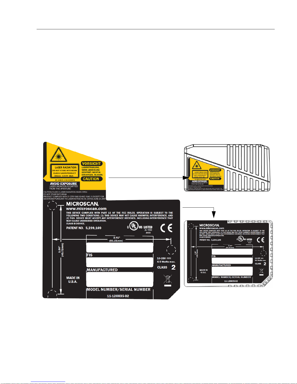
Approvals
Side View with Safety Label
Base View with Approvals Label
This equipment is in compliance or approved by the following organizations:
• UL (Underwriters Laboratories, Inc.)
• cUL (UL mark of Canada)
• FCC (Federal Communication Commission)
• CE Compliant
• BSMI (Bureau of Standards, Metrology and Inspection)
Safety Labels
The following labels are located on the side and back of the MS-9 Scanner:
MS-9 Scanner User’s Manual xi
Page 12
Warning and Caution Summary
This equipment has been tested and found to comply with the limits for a Class A digital
device, pursuant to part 15 of the FCC Rules. These limits are designed to provide reasonable protection against harmful interference in a residential installation. This equipment generates, uses, and can radiate radio frequency energy, and, if not installed and
in accordance with the instructions, may cause harmful interference to radio com-
used
will
munications. However, there is no guarantee that interference
ular installation. If this equipment does cause harmful interference to radio or television
reception, which can be determined
encouraged to try to correct the interference by one or more of the following measures:
• Reorient or relocate the receiving antenna
• Increase the separation betwe
• Connect the equipment into an outlet on a circuit different from that to which the
receiver is connected
• Consult the dealer or an experienced radio/TV technician for help
For connection to a UL listed direct plug-in power unit marked Class II and rated 10 to
28 VDC
European models must use a similarly rated Class I or Class II power supply that is
certified to comply with standard for safety EN 60950.
at 5 watts or greater.
by turning the equipment off and on, the user is
en
the equipment and receiver
not occur in a partic-
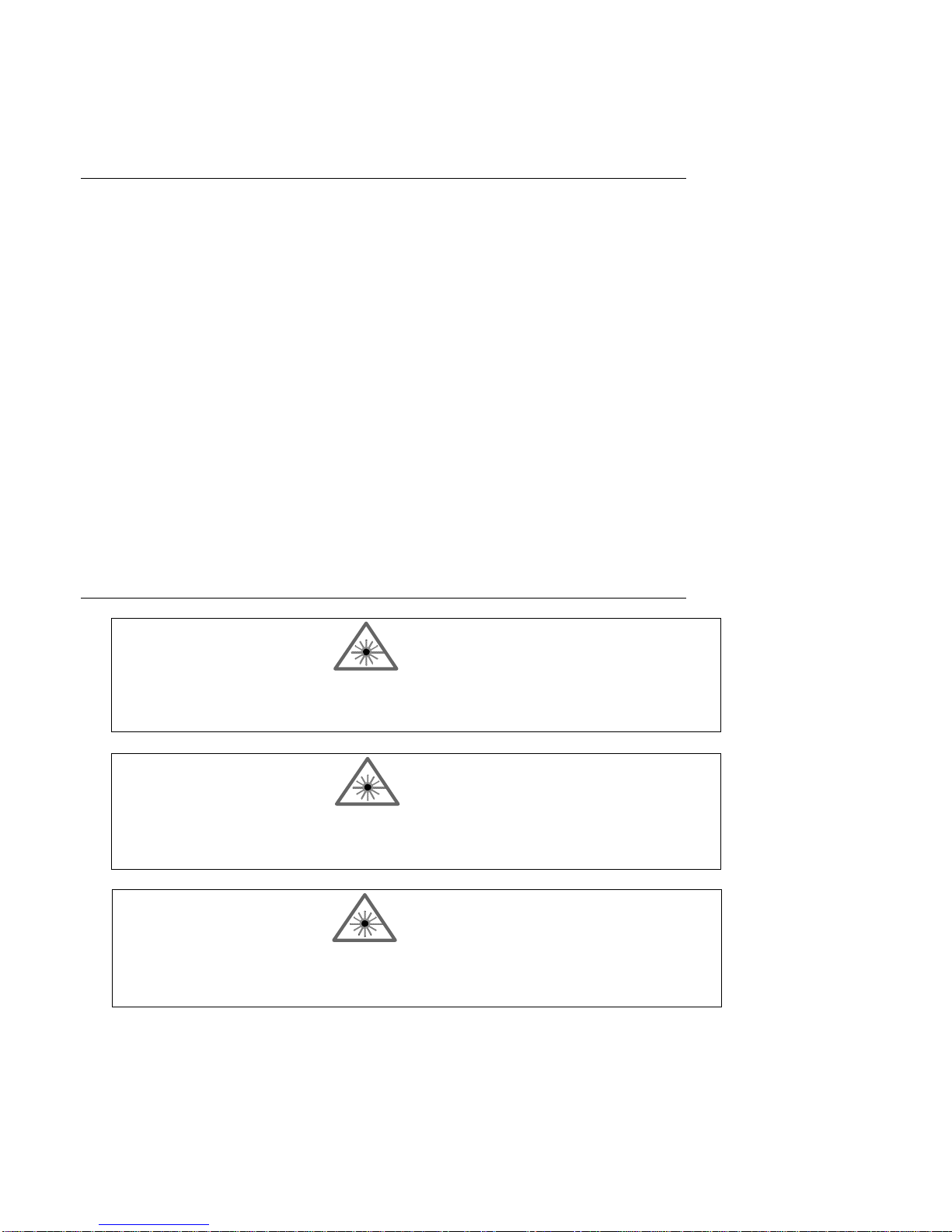
WARNING
Use of controls, adjustments, or performance of procedures other than
those specified herein may result in hazardous laser light radiation
exposure.
WARNING
There are no user serviceable parts in the scanner. Opening the scanner voids the Microscan Systems warranty and could expose the user
to laser diode power of up to 7 mW.
WARNING
The laser beam can be harmful to eyesight. Avoid eye contact with the
laser beam. Never point the beam at other peop le, or in a direction
where people may be passing.
xii MS-9 Scanner User’s Manual
Page 13

Chapter
1
Quick Star t
Chapter Contents
Step 1 Hardware Required ......................................................................1-2
Step 2 Connect the System .....................................................................1-3
Step 3 Install ESP....................................................................................1-4
Step 4 Select Scanner Model ..................................................................1-5
Step 5 Autoconnect .................................................................................1-6
Step 6 Position Symbol and Scanner ......................................................1-7
Step 7 Test for Read Rate .......................................................................1-8
Step 8 Configure the Scanner .................................................................1-9
This chapter is designed to get your scanner up and running quickly using Microscan’s
ESP so the user can get a sense of its capabilities and test bar code symbol samples.
Detailed setup information for installing the scanner into the actual application can be
obtained in the subsequent chapters. ESP is Microscan's proprietary Easy Setup Program, a Windows based graphic user interface that resides on the user's host computer and allows the user to fully configure, test,
symbology scanners.
As an alternative to ESP, you
using the scanner’s embedded menus.
and oper
can setup the scanner by sending serial commands or by
ate Microscan's 1D and 2D
MS-9 Scanner User’s Manual 1-1
Page 14
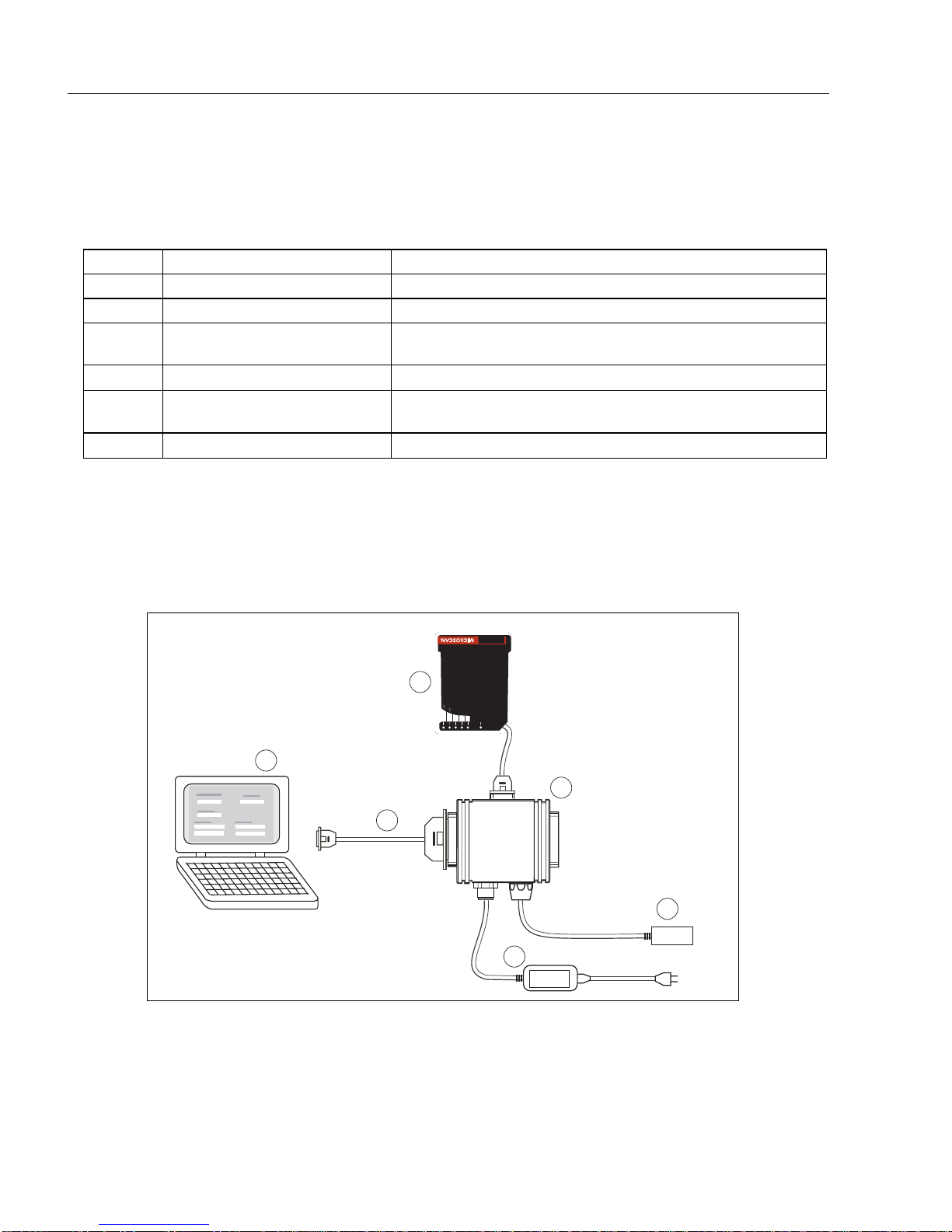
Hardware Required
Step 1 — Hardware Required
(Refer to figure 1-1.)
Item Part Number Description
1 FIS-0911-XXXXG MS-
2 Host Computer
3 61-300026-03
4
5
6
a. With either a terminal communications program or Microscan’s ESP which runs under Windows
operating system, Windows 98 or higher, including Windows NT and Windows XP.
b. If using another host cable, make certain it does not have RTS/CTS connected to the host.
99-000018-01
97-100004-15
(90-264 VAC, 24VDC)
99-000017-01 Optional object detector
Caution: If using your own power supply, be certain that it is wired correctly and supplies voltage is within the +10 to 28 VDC limits. Incorrect wiring or voltage can cause
software or equipment failures.
9 Laser Scanner
a
Cable, Communication, DB-25 Plug to DB-9 Socket,
6 foot.
b
IB-131 interface Box
Power supply
1
GOOD
READ
STA-
TUS
4060802
0
%
100
R
POWE
2
Scanner
3
Host
TriggerPower
5
Figure 1-1 Hardware Configuration
4
Network
6
1-2 MS-9 Scanner User’s Manual
Page 15
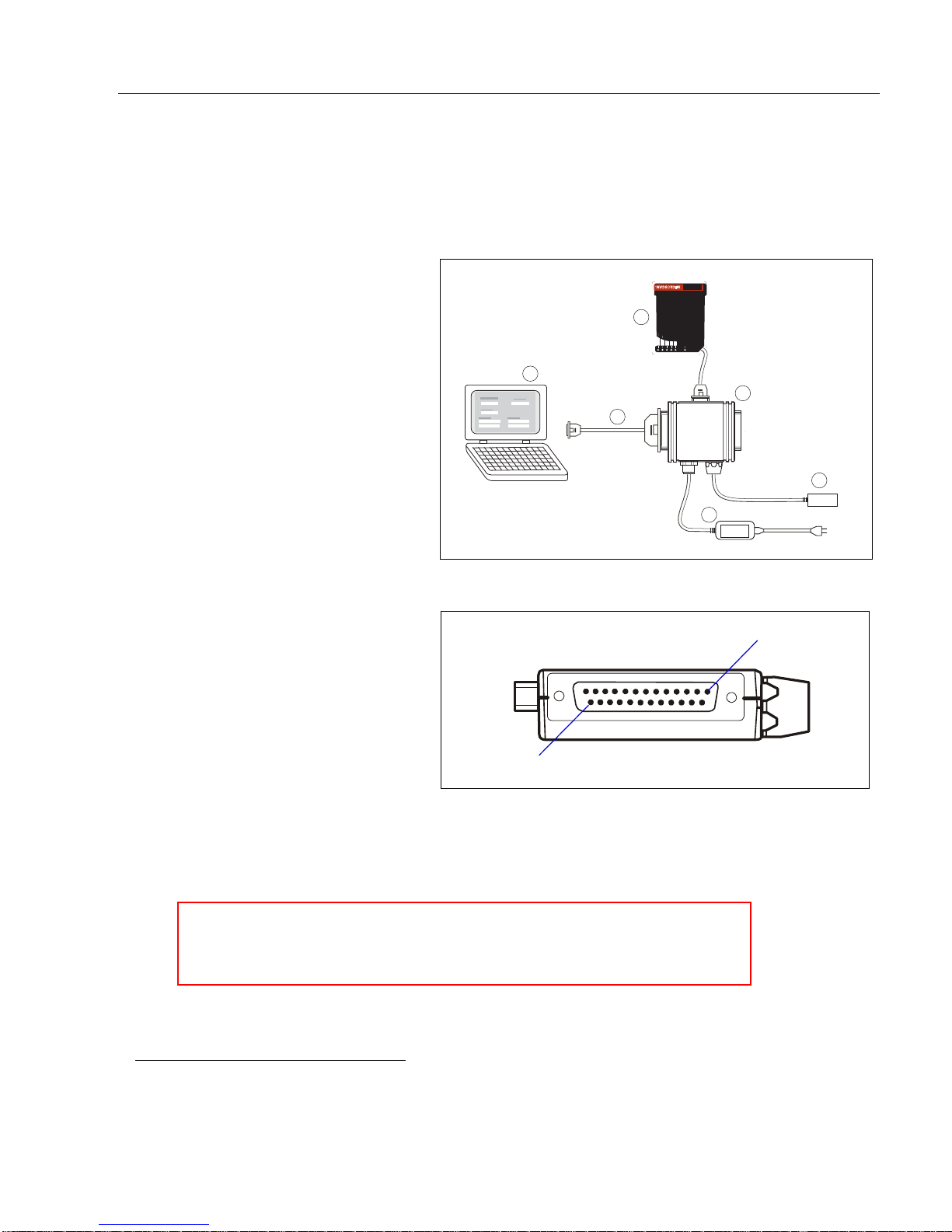
Step 2 — Connect the System
(Refer to figure 1-3.)
1. Connect the scanner (1) to
the IB-131 interface box (4).
2. Connect the IB-131 (4) at
the “HOST” 25-pin connector to the computer (2) via
a null modem cable (3).
3. Connect the power supply
(5) to the IB-131’s POWER
connector. (Refer to “IB-
131 Interface Module”
on page A-10 for pin con-
nections.)
4. Apply power to the system.
1
Chapter Quick Start
1
GOOD
READ
STA-
TUS
4060802
0
%
100
R
POWE
2
3
Scanner
Host
4
Network
TriggerPower
6
5
Figure 1-2 Hardware Configuration
25
Figure 1-3 Side View of IB-131 showing
Host 25-pin Connector
Caution:
1. Be sure all cables are connected BEFORE applying power.
2. Always power down BEFORE disconnecting any cables.
1
1. When wiring the IB-131 to a host computer which has a 25-pin connector, cross pins 2 and 3.
When wiring the IB-131 to a host computer which has a 9-pin connector, do NOT cross pins 2
and 3.
MS-9 Scanner User’s Manual 1-3
Page 16

Install ESP
Step 3 — Install ESP
1
(ESP is short for Easy Setup Program.)
With your scanner connected to a host computer with Windows operating system, you
can use the ESP to configure and control the scanner.
1. Insert your Microscan CD into yo
2. Launch Setup.exe
If downloading from the web:
a) Go to http://www.microscan.
b) Enter company information.
c) Select ESP and download to your comput
d) Extract ESP WinZip files to a directory of your choice.
3. Note where your ESP.exe file is stored on yo
At the end of the install process, copy a shor
under ESP and follow the prompts.
ur computer’s CD drive.
com/downloadcenter/
er hard drive.
ur hard drive.
tcut of the ESP icon to the desktop.
4. Click the ESP ico
n to start the program.
1. You can also access the scanner through its embedded menus. See “Embedded Menus” on
page A-20.
1-4 MS-9 Scanner User’s Manual
Page 17
Chapter Quick Start
Step 4 — Select Scanner Model
When you start the program, the following menu will appear:
Note: If you need to select another model later, you can find it in the App Mode under
Model on the menu bar.
1. In the Model dialog
If you do not want to make this selection every time you load ESP, uncheck Show
this window at Startup.
box, select your model.
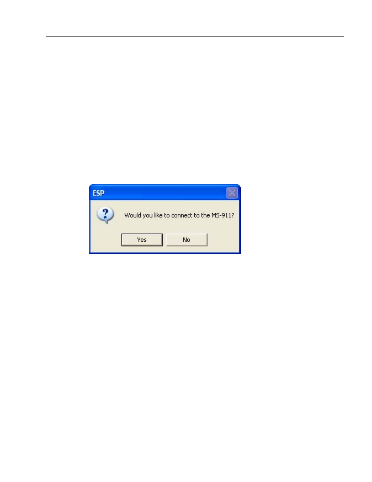
2. Select the default name, for example MS-9-1, or type in
choice and click OK.
3. Click Yes when the connect to the scanner dialog appears.
a file name of your
MS-9 Scanner User’s Manual 1-5
Page 18

Autoconnect
Step 5 — Autoconnect
1. In the Connecting to... dialog, select your communications port under COM
Port.
2. Click the Start button.
3. Allow time for the autoconnect routine to test all of the combinations. You will see
a blue
When connected, the CONNECTED message will appear in a green box in the status bar on
the bottom right of the dialog.
Tip: If connection fails, enable a different Com port and try again.
Tip: If you do not see either the CONNECTED or DISCONNECTED message at the bot-
tom of your dialog, try expanding the ESP window horizontally.
progress bar fill across the Connecting to ... dialog.
1-6 MS-9 Scanner User’s Manual
Page 19
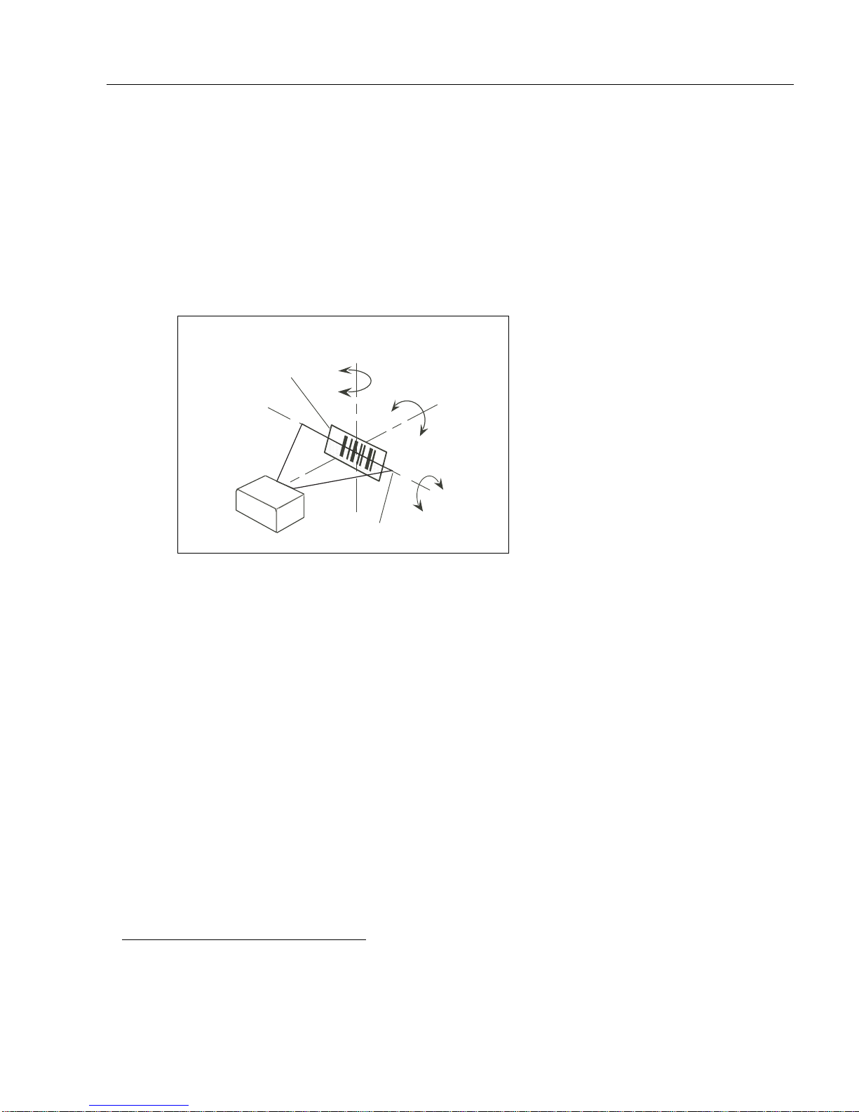
Step 6 — Position Symbol and Scanner
h
t
is
Skew
S
Chapter Quick Start
1. Set up a bar code symbol1 at the scanning distance you will be using in your
application.
2
2. Avoid bright light or IR light from other sources, including other scanners.
3. Pitch symbol or scanner a minimum of ±15° to avoid specular reflection, the
return
of direct, non-diffused light.
Bar code
label
canner
axis
Scan line
Til
ax
Pitc
axis
Figure 1-4 Symbol/Scanner Position
For read ranges, see figure A-3 on page A-5.
Code 39 is the default symbol type enabled. If you are uncertain as to your symbology
type, enable all codes (see “Autodiscriminate” on page 5-22).
1. If using an I 2/5 symbol, verify that the number of characters in the symbol being scanned
matches the symbol length enabled for the I 2/5 symbol type (default is 10 and 6). See “Inter-
leaved 2 of 5” on page 5-8.
2. Consult “LE
D Indicators” on pag
e A-4.
MS-9 Scanner User’s Manual 1-7
Page 20
Test for Read Rate
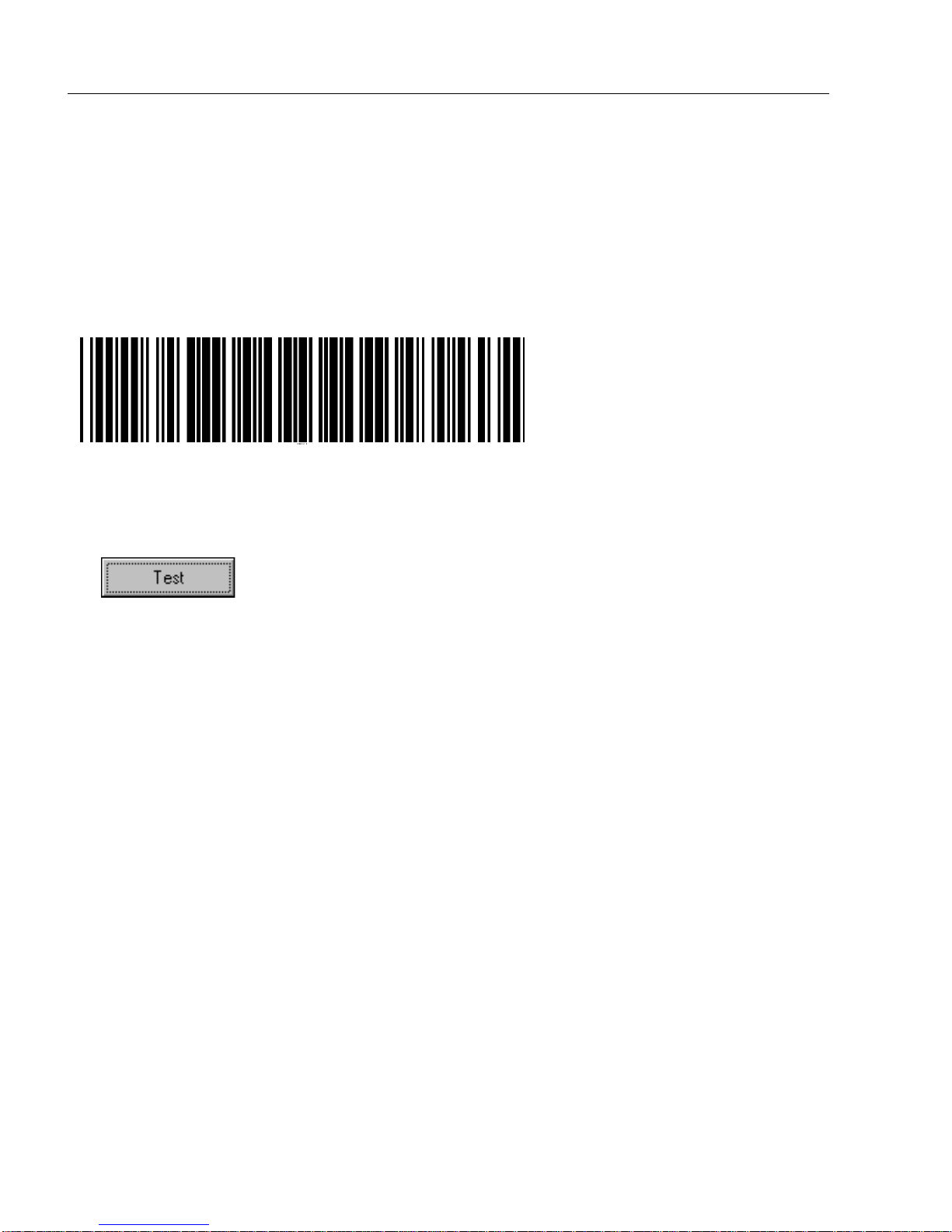
Step 7 — Test for Read Rate
If you don’t have a test symbol, print out this page and use the symbol here for
testing. With this test you can learn the percentage
observing the LEDs (20% through 100%) on the top of the scanner which are active
during a read rate test.
By ESP
After connecting to the scanner, ESP will open in Setup Mode.
1. Click the Test button in Setup Mode to begin the read rate test.
of decodes per images captured by
20 mil Code 39 Test Symbol
You can also find test symbols on the
back of the Microscan Marketing CD
jacket. The 20 mil refers to the width of
the narrowest bar (e.g., 7.5 mil =
.0075" or .1905 mm).
2. Follow the instructions in Setup Mode screen.
3. To end the Read Rate test, click the Stop button.
Note: If the scanner is in the default Contin
repeatedly as long as a readable symbol remains in the read range and the read cycle
configuration has not changed.
Note: S
mation on scan width and depth of field.
ee “Formulas for Number
of Decodes” on page A-27 for additional infor-
uous Read mode, it will read and beep
By Serial Commands
Send an <C> to begin the read rate test.
Send a <J> to end the read rate test.
1-8 MS-9 Scanner User’s Manual
Page 21
Chapter Quick Start
Step 8 — Configure the Scanner
By ESP
To make change scanner settings, or to access the utilities or terminal window, click on
the App Mode button.
To return to the Setup Mode, click on
See Chapter
2, “Using ESP” for detailed explanation of ESP features.
the Setup Mode button.
By Serial Commands
From your terminal program or the terminal screen in ESP, you can enter serial string
commands configuration and utility commands as described herein.
See “Serial Configuration Comm
Serial Commands” on page 12-3.
Note: You can learn the current setting of any parameter
after the number, as in <KA?> To see all “K” commands, send <K?>.
ands” on page A-13 and “Summary of Utility
by inserting a question mark
By Embedded Menu
From your terminal program you can send a <D> command to access the embedded
menus.
See “Embedded Menus” on page A-20.
MS-9 Scanner User’s Manual 1-9
Page 22

Configure the Scanner
1-10 MS-9 Scanner User’s Manual
Page 23

Chapter
2
Using ESP
Chapter Contents
Setup Mode .............................................................................................2-2
Application Mode .....................................................................................2-3
Pulldown Menus ......................................................................................2-4
Making Changes in ESP..........................................................................2-6
Send/Receive Options .............................................................................2-7
This section is designed to help you understand the structure, elements, and application
of the ESP (Easy Setup Program).
When you start up ESP, unless otherwise specified, you will enter the Setup Mode for
initial setup
you can access several configuration and utilities menus.
. From there, you move easily into the App Mode (application mode) where
MS-9 Scanner User’s Manual 2-1
Page 24
Setup Mode
Setup Mode
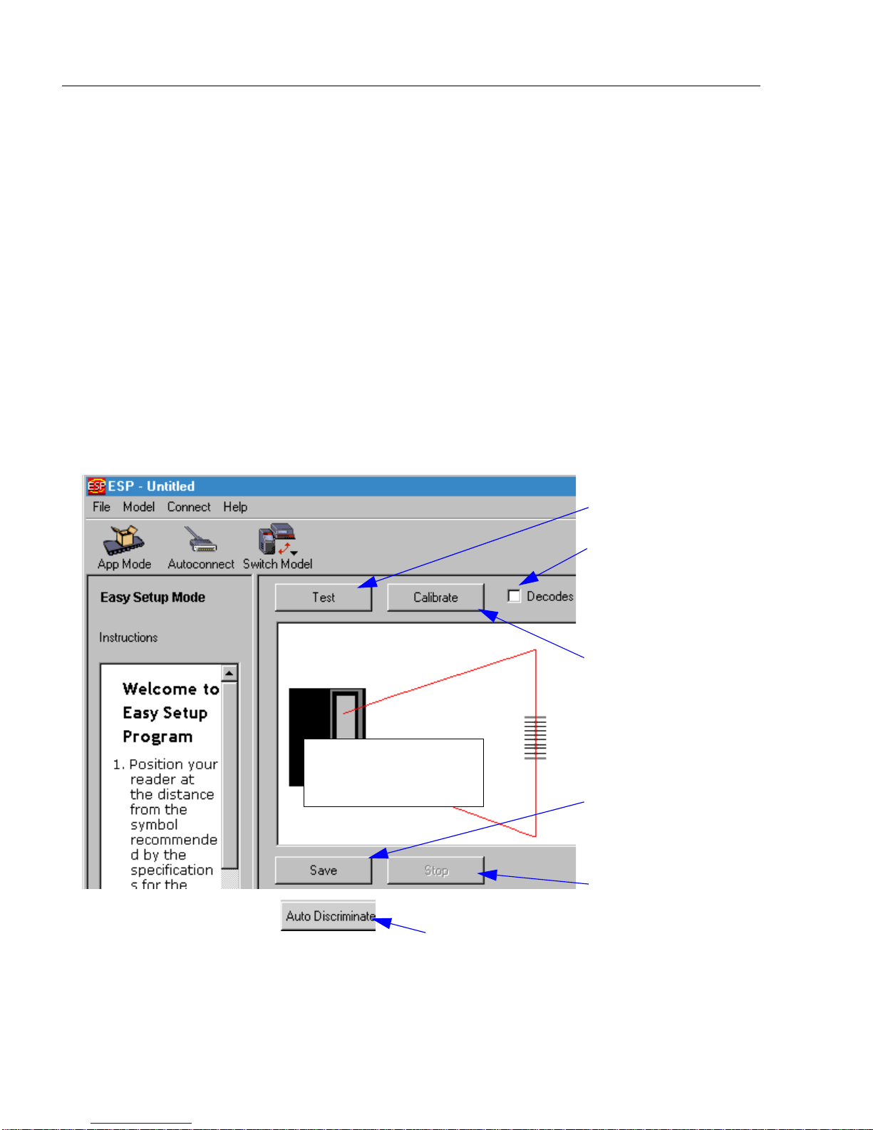
In Setup Mode you are presented with the Test option and if appropriate for your
application, Calibration. After connecting to your scanner (or scanner) the Setup
Mode will first appear. This will provide you with instructions specific to your model that
will help you in positioning, testing, and if appropriate, calibrating.
Test
Click the Test button to start the read rate test for a quick indication of the read capabilities and the limits of your application. When Decode
the test will count the percentage of decodes relative to the number of actual scans.
Click Stop to end the test.
Calibrate
Some models include a calibration routine that will optimize reads by comparing read
rates at various settings in focal lengths, scan speeds, and gain settings.
s per Second is unchecked,
Test button
Note: This view may be
slightly different for each
model.
On some models, clicking Auto Discriminate
will enable most available symbology types.
Click here to change
from percentage of
good decodes to
decodes per second
Calibration is available on some models
Saves Calibration
results (if available)
Ends the read rate
test
2-2 MS-9 Scanner User’s Manual
Page 25
Chapter 2 Using ESP
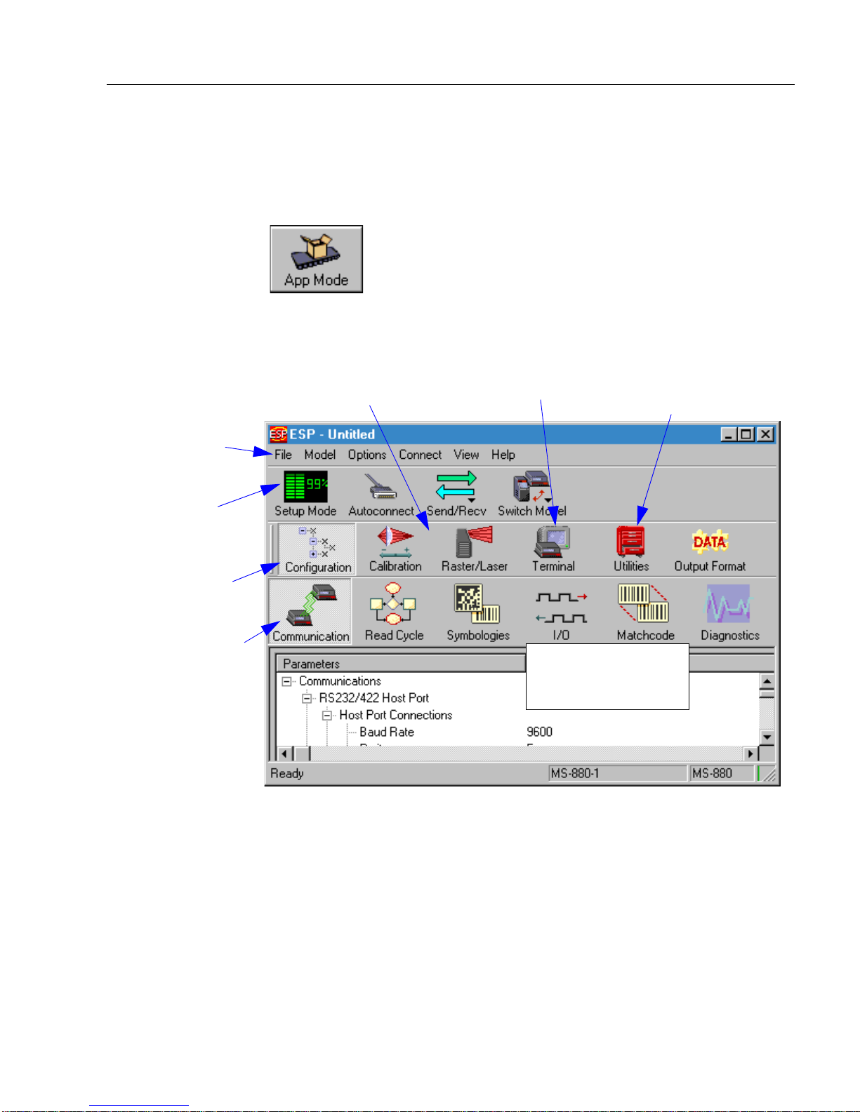
Application Mode
From Setup Mode, you can click on the App Mode button to access specific configuration menus, utilities, and a terminal window where serial commands can be
entered.
Note that the App Mode and Setu
p Mode buttons appear in the same position to allow
easy switching between these primary modes.
The icons on this
toolbar are for operations
Pulldown menus
Click this icon to
return to Setup
Mode
Click this icon to
return to this view
from Utilities or
Terminal
Click on icons in this
toolbar to access
configuration menu
trees to make specific changes in configuration
Click here to open
a terminal window
Note: This view may be
slightly different for
each model.
Click here to
access read rate
and other utilities
Note: F
or specific information on any of the icons shown abov
configuration bar, see specific chapters in this document.
e in the operations bar or
MS-9 Scanner User’s Manual 2-3
Page 26
Pulldown Menus
Pulldown Menus
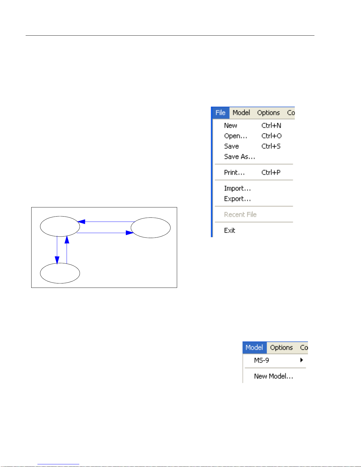
File
New
Whenever New is selected, the default configuration of ESP is loaded.
Open/Save
When Save or Save As is selected, the ESP configuration is saved to the host computer’s hard
drive
selected under Open.
Important: When y
your hard drive, these changes are not saved to
your scanner. Figure 2-1 shows how settings can
be saved and received between ESP and the scanner and ESP and the host hard drive.
and available whenever the same file is
ou sav
e menu changes to
Receive Scanner Settings
ESP
File
Save
Host hard
drive
Save to Reader
File
Open
Figure 2-1 How Settings
are Saved
Scanner
Import/Export
Export converts the active ESP configuration settings to an ASCII text file. Import
converts the ASCII settings from a text file to ESP configuration settings.
Model
When you select New Model, you can define configuration settings for another model. When you save to the hard drive, you
will be saving
ESP file.
the settings of all the models defined in a single
2-4 MS-9 Scanner User’s Manual
Page 27
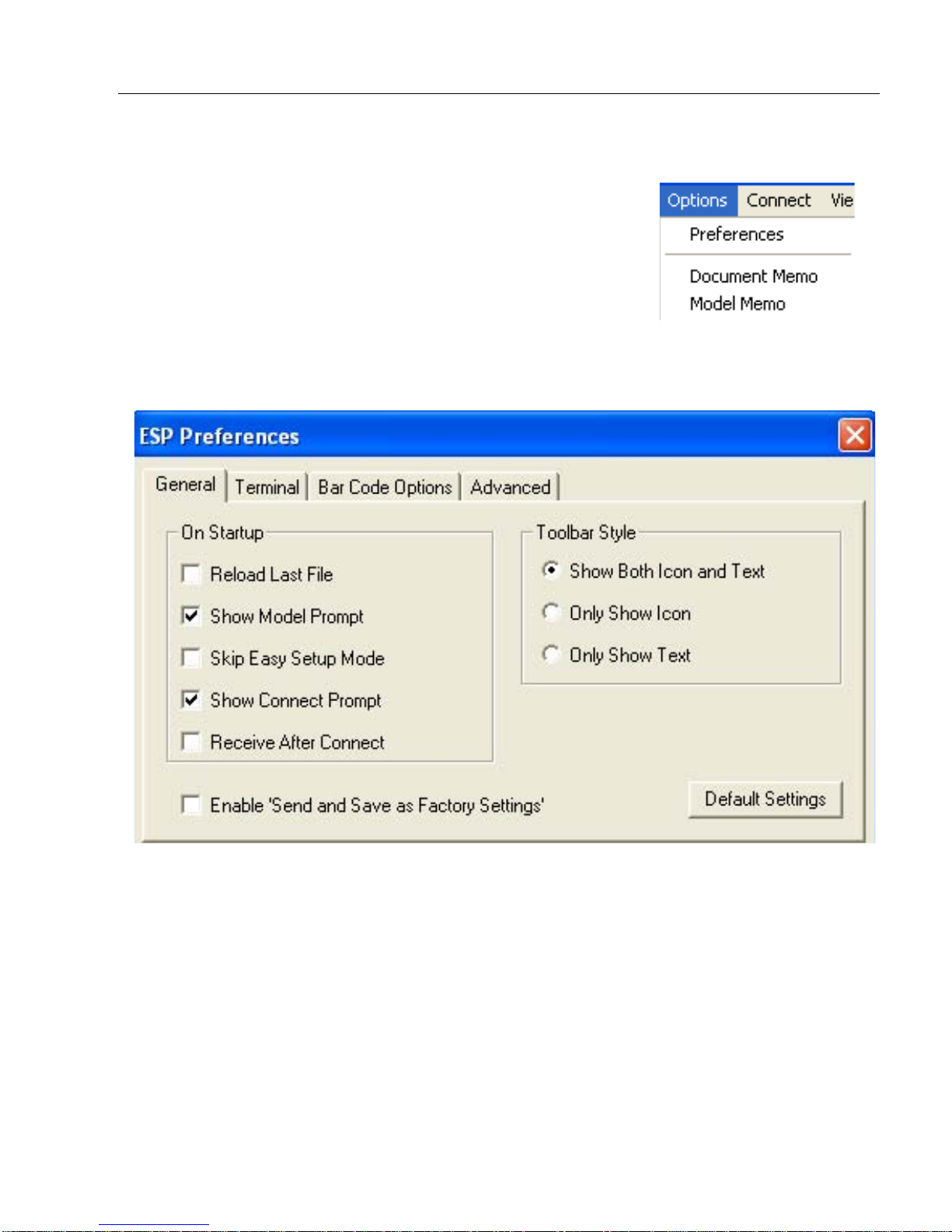
Options
You can use the Options menu to tell ESP how you wish
it to perform at startup.
Note: The setting
loaded into ESP when ESP is opened next, whether or not
you save the ESP file to the computer.
Preferences
Opens a dialog box that allows you to determine how you
want ESP to behave on Startup.
s you select here will be saved and be
Chapter 2 Using ESP
Document Memo (Options menu)
Allows you to describe a new document.
Model Memo (Options menu)
Allows you to describe the model currently in use.
MS-9 Scanner User’s Manual 2-5
Page 28
Pulldown Menus
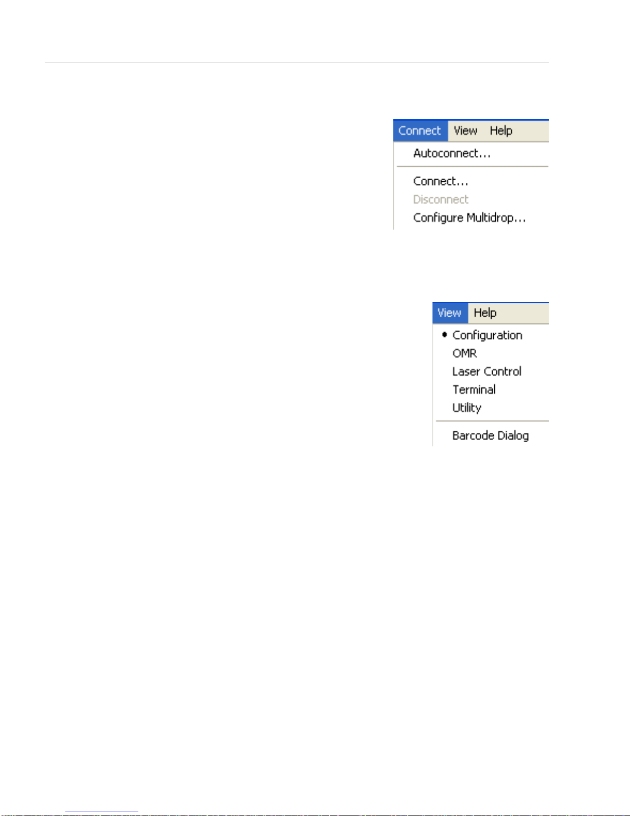
Connect
Generally Autoconnect will be the quickest way that ESP
can get connected to a scanner. Autoconnect will try connecting at the most common communications settings and
throug
step
the host’s settings.
When you select Connect, you will need to manually
select the communications settings from a popup dialog.
h the various settings until they match up with
View
View tells you what view is current and allows you to quickly
move to other views which are also accessed by clicking the icons
on the toolbars.
2-6 MS-9 Scanner User’s Manual
Page 29
Chapter 2 Using ESP
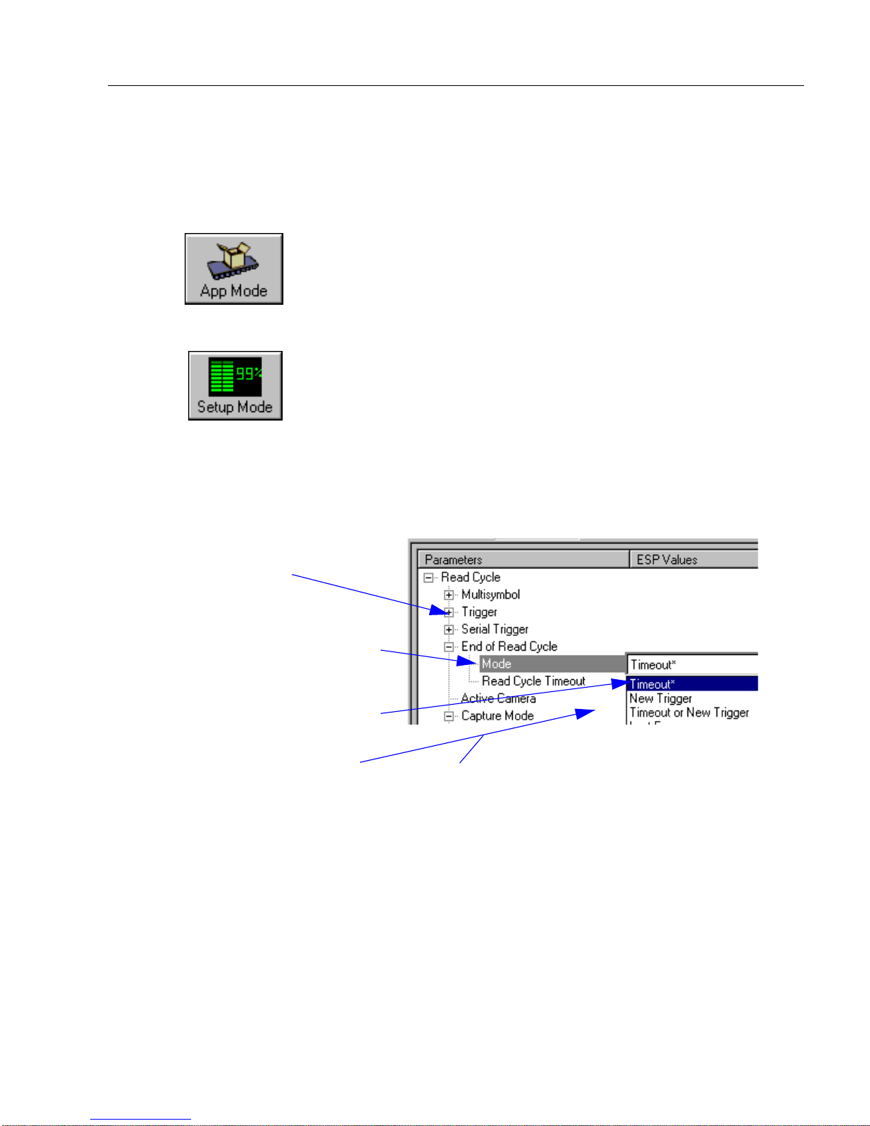
Making Changes in ESP
To change scanner settings, or to access the utilities or terminal window, click on the
App Mode button.
To return to the Se
See the succeeding chapters and Appendices to see specific configuration command
explanations for both ESP and serial commands.
To make changes to a configuration setting in the menu trees:
1. Left click on the + to
expand tree
2. Double click on parame-
ter and click once in selection box to view options.
3. Place your curser in the
selection box, scroll down
to the setting you want to
change and click once on
the setting.
4. Left click again on the
open screen to complete
the selection.
tup Mode, click on
the Setup Mode button.
5. Right click on the open screen and select
Save to Reader to implement the command
in the scanner.
MS-9 Scanner User’s Manual 2-7
Page 30
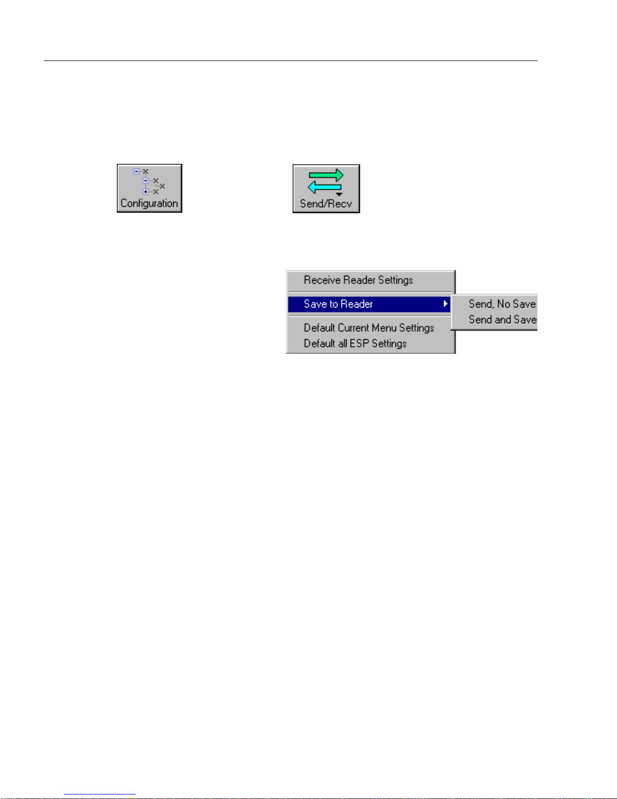
Send/Receive Options
Send/Receive Options
To access save and receive options, from the Configuration views click the
Send/Recv button:
can also access this selector by right-clicking in any of the configuration views.
You
Saving
You have 3 choices for saving:
1. Send, No Save.
This saves ESP settings to current
memory.
2. Send and Save.
Thi
s activates all changes in cur-
rent memory and saves
mand.)
to the scanner for power-on. (Similar to the <Z> com-
3. Send and
factory settings.
For Multidrop setup, see “Multidrop Communications” on page A-32.
For Matchcode setup, see Chapter 6, “Matchcode.”
For more on defaulting and saving settings, see “Defaulting/Saving/Initializing” on
page A-21.
Save, Including Factory. Incl
udes all settings including changes to
Receiving
From the Send/Recv selector select Receive Scanner Settings.
This is useful if you want to receive (upload) the scanner’s settings and save them as a
computer file for later retrieval and to verify that your ESP settings have been saved or
that you have not saved any unwanted changes that you or someone else previously
made in ESP.
Defaulting
When you select Default Current... or Default all ESP... you are only defaulting the
ESP settings. To default the scanner, see “Defaulting/Saving/Initializing” on page
A-21 for a more information.
2-8 MS-9 Scanner User’s Manual
Page 31

Chapter
3
Communications
Chapter Contents
Communications by ESP......................................................................... 3-2
RS-232/422 Host Port ............................................................................. 3-3
RS-232 Auxiliary Port .............................................................................. 3-9
Preamble ............................................................................................... 3-16
Postamble..............................................................................................3-17
LRC Status ............................................................................................ 3-18
Response Timeout ................................................................................3-19
Intercharacter Delay .............................................................................. 3-20
With Microscan’s ESP™ (Easy Setup Program), configuration changes can be made in
the ESP menus, then sent and saved to your scanner. The user can also send serial
commands to the scanner via the ESP’s Terminal window.
This section includes connecting parameters and options for communicating by the auxiliary port and various interfaces.
Note:
can only be entered through embedded menus, not through ESP or serial commands.
Note: Default
When assigning characters in user-defined fields, the characters NULL
settings for establishing communications are:
Baud = 9600
Parity = Even
Stop Bits = One
Data Bits = Seven
Flow Control = No
ne
<> and ,
MS-9 Scanner User’s Manual 3-1
Page 32

Communications by ESP
Communications by ESP
Click this button to bring up
the Communications menu.
To open nested options,
single-click the +.
To change a setting,
double-click the
setting and use your
cursor to scroll
through the options.
3-2 MS-9 Scanner User’s Manual
Page 33

Chapter 3 Communications
RS-232/422 Host Port
Includes host port connections and host protocols.
Host Port Connections
Baud Rate, Host Port
Usage: Can be used to transfer data faster or to match host port settings.
Definition: The rate at which the scanner and host transfer data back and forth.
Serial Cmd: <K101,aux port mode,baud rate,parity,stop bits,data bits,daisy chain
ID status,daisy chain ID>
Default: 9600
Options: 1 = 1200
2 = 2400
3 = 4800
4 = 9600
5 = 19.2 K
6 = 38.4 K
7 = 57.6 K
8 = 115.2 K
Parity, Host Port
Usage: Only changed if necessary to match host setting.
Definition: An error detection routine in which one data bit in each character is set to
1 or 0 so that the total number of 1 bits in the data field is even or odd.
Serial Cmd: <K100,baud rate,parity,stop bits,data bits>
Default: Even
Options: 0 = None 1 = Even 2 = Odd
Stop Bits, Host Port
Usage: Only changed if necessary to match host setting.
Definition: One or two bits added to the end of each character to indicate the end of
the character.
Serial Cmd: <K100,baud rate,parity,stop bits,data bits>
Default: One
Options: 0 = One 1 = Two
MS-9 Scanner User’s Manual 3-3
Page 34

RS-232/422 Host Port
Data Bits, Host Port
Usage: Only changed if necessary to match host setting.
Definition: Number of bits in each character.
Serial Cmd: <K100,baud rate,parity,stop bits,data bits>
Default: Seven
Options: 0 = Seven 1 = Eight
Host Protocol
Usage: In general, the point-to-point protocols will work well in most applica-
tions. They require no address and must use RS-232 or RS-422 communications standards.
Definition: Protocols define the sequence and format in which information is trans-
ferred between the scanner and the host, or in the case of Multidrop,
between scanners and a concentrator.
Serial Cmd: <K140,protocol>
Default: Point-to-Point
Options: 0 = Point-to-Point
1 = Point-to-Point with RTS/CTS
2 = Point-to-Point with XON/XOFF
3 = Point-to-Point with RTS/CTS &
XON/XOFF
If selecting one of the options from 0 to 4 (Point-to-Point, Point-to-
Point with RTS/CTS, Point-to-Point with XON/XOFF, Point-to-
Point with RTS/CTS and XON/XOFF, or Polling Mode D), use the
<K140,protocol> format.
Option 5 through 7 are special cases and discussed later in this section.
4 = Polling Mode D
5 = Multidrop
6 = User Defined
7 = User Defined Multidrop
Point-to-Point (standard)
Usage: Used only with RS-232 or RS-422.
Definition: Standard Point-to-Point requires no address and sends data to the host
whenever it is available, without any request or handshake from the host.
Serial Cmd: <K140,0>
3-4 MS-9 Scanner User’s Manual
Page 35

Chapter 3 Communications
Point-to-Point with RTS/CTS
Usage: A scanner initiates a data transfer with an RTS (request-to-send) trans-
mission. The host, when ready, responds with a CTS (clear-to-send) and
the data is transmitted. CTS and RTS signals are transmitted over two
dedicated wires as defined in the RS-232 standard.
Used only with RS-232.
Definition: Point-to-Point with RTS/CTS (request-to-send/clear-to-send) is a
simple hardware handshaking protocol that allows a scanner to initiate
data transfers to the host.
Serial Cmd: <K140,1>
Point-to-Point with XON/XOFF (Transmitter On/Off)
Usage: If an XOFF has been received from the host, data will not be sent to the
host until the host sends an XON. During the XOFF phase, the host is free
to carry on other chores and accept data from other devices.
Used only with RS-232.
Definition: This option enables the host to send the XON and XOFF command as a
single byte transmission command of start (^Q) or stop (^S).
Serial Cmd: <K140,2>
Point-to-Point with RTS/CTS & XON/XOFF
Usage: Used only with RS-232.
Definition: This option is a combination of Point-to-Point with RTS/CTS and
Point-to-Point with XON/XOFF.
Serial Cmd: <K140,3>
Po lling Mo de D
Usage: When in Polling Mode D, an address of 1 is automatically displayed on
the configuration screen. However, during transmission, a 1C hex poll
address (FS) and a 1D hex select address (GS) are substituted for the 1.
Definition: Like Point-to-Point, Polling Mode D requires a dedicated connection to
the host; but unlike Point-to-Point, it requires an address and must
wait for a poll from the host before sending data.
Serial Cmd: <K140,4>
MS-9 Scanner User’s Manual 3-5
Page 36

RS-232/422 Host Port
Multidrop
Note: See also “Multidrop Communications” on page A-32.
Usage: The MS-5000 can be used as a concentrator to a single host port connec-
tion.
Definition: Multidrop allows up to 50 devices to be connected to a single RS-485
host, with the scanner assigned an unique address (from 01 to 50). When
Multidrop is selected, the protocol characters for RES, REQ, etc. are
assigned automatically.
Multidrop
Addresses:
Options: 01 through 50
Serial Cmd: If selecting Multidrop <
Each address has its own separate poll and select address (from 1C to 7F
hex).
K140,5>
appended to the command string.
Format: <K140,5,
address[01 to 50]>
fan address must be defined and
Note: Scanners
configured in standard multidrop protocol.
linking up to a Microscan MS-5000 multidrop concentrator must be
User Defined Point-to-Point
Usage: Used for
Definition: User Defined Point-to-Point allows the user to customize the point-to-
point protocol.
Serial Cmd: <K140,6,RES,address,REQ,EOT,STX,ETX,ACK,NAK,from host>
User Defined Address
Definition: User Defined is considered to be in a polled mode only if an address has
been assigned.
Serial Cmd: <K140,6,RES,address,REQ,EOT,STX,ETX,ACK,NAK,from host>
Default: No address
Options: Any ASCII character except a null.
User Defined Example
Example: An ACK/NAK protocol can be configured using User Defined. The scan-
ner will transmit data to the host when an ACK is received. If a NAK or
response timeout occurs, the scanner will re-send the data to the host up
to 3 more times before aborting.
developing custom protocols in polled or unpolled mode.
Serial Cmd: <K140,6,RES,address,REQ,EOT,STX,ETX,ACK,NAK,from host>
Default: No assignment
Options: Any ASCII character except a null. Control characters can be used to
define RES through NAK in serial commands.
3-6 MS-9 Scanner User’s Manual
Page 37

Chapter 3 Communications
From Host
Definition: Allows the handshaking protocol to be initiated from the host, if not con-
figured in an unpolled mode. Messages sent to the host will include the
scanner’s defined protocol. The status of From Host determines if mes-
sages sent from the host to the scanner must include the defined proto-
col. If From Host is disabled, the defined protocol is not included. If
From Host is enabled, the defined protocol must be included.
Serial Cmd: <K140,6,RES,address,REQ,EOT,STX,ETX,ACK,NAK,from host>
Default: Disabled
Options: 0 = Disabled 1 = Enabled
MS-9 Scanner User’s Manual 3-7
Page 38

RS-232/422 Host Port
User Defined Multidrop
Note: Any ASCII character except a null (00) and a ^A (01) can be assigned as an
address. Control characters can be used to define RES through NAK in serial commands. See (See “Communication Protocol Com
Usage: Used when connecting to a concentrator or other device that does not
match standard multidrop protocol.
Definition: User Defined Multidrop allows the user to customize the polling protocol.
If selecting User Defined Multidrop (7), complete the format by either
choosing new parameters or place commas where unchanged data fields
occur.
Serial Cmd: <K1
Address: Any single character (02 hex to 7E hex) in the ASCII table can be
40,7,RES,
For User Defined Multidrop, first select Multidrop <K140,5>, then
User Defined Multidrop <K140,7...>.
assigned as the address character. The character chosen is used as the
poll character and the subsequent ASCII character becomes the select
character. For example, if a ^B (02 hex) is selected as the address, ^C
(03 hex) becomes the select address that the host will use in sending
host select commands.
address,REQ,EOT,STX,ETX,ACK,NAK>
mand
s” on page A-19.)Note:
Definitions of commands in User
cated in host applications to enable poll and select se
ing transmission.
Note: Typically, parameters in User
Multidrop, then enabling User Defined Multidrop. This pre-loads multidrop charac-
ters into the parameters. Then changes are made
host or other requirements.
Defined and User Defined Multidrop must be dupli-
quences to execute correctly dur-
Defined Multidrop are defined by first enabling
to individual characters
to match the
Host RS-422 Status
Usage: Only changed
Definition: Enables RS-422. When RS-422 is enabled, RS-232 is disabled.
Serial Cmd: <K102,status>
Default: Disabled
Options: 0 = Disabled 1 = Enabled
if necessary to match
host setting.
3-8 MS-9 Scanner User’s Manual
Page 39

Chapter 3 Communications
RS-232 Auxiliary Port
Note: The aux port cannot be used when the host port is set to RS-422 or Multidrop.
As with the host port parameters, the auxiliary terminal’s settings (baud rate, parity,
stop bits, and data bits) must be identical with those of the auxiliary device.
Usage: These commands set the communication parameters with the auxiliary
port which can be used to configure menus, send data to the host, dis-
play data transmissions originating from the host of the scanner, and
y data
rela
Definition: An auxiliary port connects the scanner to a remote display or to other
scanners that can display or transfer data.
Aux Port Connections
As with the host port parameters, the auxiliary terminal’s settings (baud rate, parity,
stop bits, and data bits) must be identical with those of the auxiliary device.
Baud Rate, Aux Port
from other scanners set in tandem (daisy chained).
Usage: Can be used to transfer data faster or match an auxiliary device.
Definition: The rate at which the scanner and host transfer data back and forth.
Serial Cmd: <K101,aux port mode,baud rate,parity,stop bits,data bits,daisy chain
ID status,daisy chain ID>
Default: 9600
Options: 1 = 1200
2 = 2400
3 = 4800
4 = 9600
5 = 19.2 K
6 = 38.4 K
7 = 57.6 K
8 = 115.2 K
Parity, Aux Port
Usage: Only changed if necessary to match host setting.
Definition: An error detection routine in which one data bit in each character is set to
1 or 0 so that the total number of 1 bits in the data field is even or odd.
Default: Even
Options: <K101,aux port mode,baud rate,parity,stop bits,data bits,daisy chain
ID status,daisy chain ID>
Serial Cmd: 0 = None 1 = Even 2 = Odd
Stop Bits, Aux Port
Usage: Only changed if necessary to match host setting.
MS-9 Scanner User’s Manual 3-9
Page 40

RS-232 Auxiliary Port
Definition: Allows the user
cate the end of the character.
Serial Cmd: <K101,aux port mode,baud rate,parity,stop bits,data bits,daisy chain
ID status,daisy chain ID>
Default: One
Options: 0 = One 1 = Two
to select the
last one or two bits in each character to indi-
Data Bits, Aux Port
Usage: Only changed if necessary to match host setting.
Definition: Number of bits in each character.
Serial Cmd: <K101,aux port mode,baud rate,parity,stop bits,data bits,daisy chain
ID status,daisy chain ID>
Default: Seven
Options: 0 = Seven 1 = Eight
Aux Port Mode
Note: The aux port interacts only with the host port via the 25-pin port except when in
Daisy Chain mode. When in Daisy Chain mode, the aux port will also interact with the
configuration port (9-pin port) or the wiring box network ports.
Definition: Determines the flow of data between the auxiliary
scanner, and the host.
Serial Cmd: <K101,aux
ID status,daisy chain ID>
Default: Disabled
Options: 0 = Disabled
1 = Transparent
2 = Half duplex
port mode,baud rate,parity,stop bits,data bits,daisy chain
3 = Full duplex
4 = Daisy chain
5 = Command Processing
port device(s), the
3-10 MS-9 Scanner User’s Manual
Page 41

Chapter 3 Communications
Transparent Mode
Usage: Often used in conjunction with handheld scanners. Employs an auxiliary
readout to detect mis-applied bar code symbols.
Definition: In Transparent mode data is passed between the auxiliary port and the
host. The scanner buffers data from the auxiliary port and echoes the
keyed data on the auxiliary port. I
Data initiated from the Auxiliary Port
• Auxiliary port data is passed through to the host whenever a return
key is pressed at the auxiliary port or symbol data is sent.
• Whenever aux port data is sent with symbol
data, the aux port data will appear between the
Host
preamble and the symbol data.
• Auxiliary port data to the host is always sent
with a preamble and a postamble.
• If the scanner is in a polled mode to the host,
Scanner
auxiliary port data will NOT pass through.
• <D> is the only command accepted by the
scanner from the auxiliary port. All other commands will pass through
to the host.
Aux
Port
Data initiated from the Scanner
• Transmission to the auxiliary port occurs immediately upon a good read.
• Scan data to the auxiliary port does not include
Host
Aux
Port
a preamble or a postamble.
• Communications with the auxiliary port is
always in Point-to-Point protocol, even if the
Scanner
host is in a polled protocol mode.
Data initiated from the Host
• All host data is echoed to the auxiliary port in
Host
Aux
Port
unpolled mode.
Scanner
Serial Cmd: <K101,aux port mode,baud rate,parity,stop bits,data bits,daisy chain
ID status,daisy chain ID>
1 = Transparent
Half Duplex Mode
Usage: Used to display symbol data on an auxiliary screen close to the scanner.
MS-9 Scanner User’s Manual 3-11
Page 42

RS-232 Auxiliary Port
Definition: In Half Duplex mode all auxiliary port data and symbol data is sent
directly to the host. Symbol data is displayed on the auxiliary port screen
at the same time the data is sent to the host.
Data initiated from the Auxiliary Port
• Auxiliary port data to the host is ignored if the
scanner is in a polled mode.
• Auxiliary port data or scanned data is sent to
the host whenever it is received.
• Auxiliary port data is not echoed.
• Auxiliary port data to the host is always sent
without a preamble or a postamble.
• <D> is the only command that is accepted by the scanner from the
auxiliary port. All other commands are passed through to the host.
Data initiated from the Scanner
• Scan data is transmitted to the auxiliary port at
the same time it is transmitted to the host.
• Data transmission conforms with all parameters
specified in the configuration menu (e.g., Pre-
amble, Postamble, End of Read Cycle).
Data is initiated from the Host
Host
Scanner
Host
Scanner
Aux
Port
Aux
Port
• All host data is echoed to the auxiliary port in
unpolled mode.
Host
Scanner
Aux
Port
Serial Cmd: <K101,aux port mode,baud rate,parity,stop bits,data bits,daisy chain
ID status,daisy chain ID>
2 = Half Duplex
3-12 MS-9 Scanner User’s Manual
Page 43

Chapter 3 Communications
Fu ll Duplex M ode
Usage: Used when communication to and from the auxiliary port is required.
Definition: In Full Duplex mode all auxiliary port data and symbol data is sent
directly to the host. Symbol data is not displayed on the auxiliary port
screen.
Data initiated from th e Au xilia ry Port.
• Auxiliary port data to the host is ignored if the
Host
scanner is in a polled mode.
• Auxiliary port data or scanned data is sent to
the host whenever it is received.
• Auxiliary port data is not echoed.
Scanner
• Auxiliary port data to the host is always sent
without a preamble or a postamble.
• <D> is the only command that is accepted by the scanner from the
auxiliary port. All other commands are passed through to the host.
Data initiated fro m th e Sca nne r.
• Scan data is not sent to the auxiliary port.
Host
Aux
Port
Aux
Port
Scanner
Data initiated from the Host
All host data is echoed to the auxiliary port in
Host
Aux
Port
unpolled mode.
Scanner
Serial Cmd: <K101,aux port mode,baud rate,parity,stop bits,data bits,daisy chain
ID status,daisy chain ID>
3 = Full duplex
MS-9 Scanner User’s Manual 3-13
Page 44

RS-232 Auxiliary Port
Conditions: The conditions for a daisy chain application are as
follows:
1. The master scanner’s trigger must be Serial
or External;
are configured for Serial.
2. All scanners are enabled to Daisy Chain
de.
mo
3.
Each scanner’s auxiliary port must be connected to the Host port of
secondary scanner.
its
4. Each secondary scanner in the daisy chain must be set to send its
no less than 20 mS before its preceding scanner.
data
5. All but the master scanner must have Post
to CR (^M) only.
6. All but the master scanner must have their noread messages disabled.
7. If Mu lt isymbol is e
must match in all scanners and Number of Symbols must be set
to number large enough to include all the symbols it may itself read
plus the number of symbols that it will be expected to relay to the
host or the next scanner up the line.
8. Symbolog
9. All but the master scanner must have their diagnostic warning messages disabled.
10. Daisy Chain ID Status
ters in Daisy Chain ID must
the secondary scanners’ triggers
nabled, Multisymbol Separator characters
enable/disable must be the same in all scanners.
y ID
enable/disable and the number of charac-
be the same in all scanners.
Host
amble enabled and set
Secondary
Master
Daisy Chain ID
Usage: Used in a daisy chain setup in cases where the host needs to know which
scanner sent the data.
Definition: A one or two character prefix which identifies the particular daisy chain
scanner from which
Serial Cmd: <K101,aux port mode,baud rate,parity,stop bits,data bits,daisy
status,daisy chain ID>
Default: 1/
Options: Any one or two ASCII characters.
3-14 MS-9 Scanner User’s Manual
the data is being sent.
chain ID
Page 45

Chapter 3 Communications
Preamble
Preamble Status
Usage: Used for identifying and controlling incoming data. For example, defining
the preamble as a carriage return and a line feed causes each decoded
message to be displayed of on its own line.
Definition: Up to four user defined ASCII characters, including control characters,
be
can
sent from the scanner to the host.
Serial Cmd: <K141,status,preamble character(s)>
Defau
Options: 0 = Disabled
lt: Disabled
1 = Enabled (within any protocol)
Preamble Character(s)
defined and added to the front or end of the data string that is
Serial Cmd: <K141,status,preamble character(s)>
Default: ^M corresponds to: carriage return/null/null/null.
Options: Up to four user-defined ASCII characters, including control characters.
Within a Serial Command
To enter control characters within a serial command, hold down the control key while typing the desired character.
Example: <KCNTL-m> to enter ^M
Within an Embedded Menu
Control characters entered on the command line are displayed in the
menu as mnemonic characters, such as: <CR><NUL><NUL><NUL>.
To enter a control character from within an embedded
a space (with the space key). This has the effect of allowing the control
key to be recognized as a part of the control character. Next hold down
the control key while typing the desired character.
Example: Sp
ace CNTL-m to enter ^M.
menu, first type in
MS-9 Scanner User’s Manual 3-15
Page 46

Postamble
Postamble
Postamble Status
Usage: Used for identifying and controlling incoming data. For example, defining
the postamble as a carriage return and a line feed causes each decoded
message to be displayed of on its own line.
Definition: Defines a one- to four-character data string that can be added to the end
of the de
Serial Cmd: <K142,status,postamble character(s)>
Default: Enabled
Options: 0 = Disabled 1 = Enabled
coded
Postamble Character(s)
Serial Cmd: <K142,status,postamble character(s)>
Default: ^M^J. Corresponds to carriage return/line feed/null/null, as displayed in
the menu.
Options: Up to four user-defined ASCII characters, including control characters.
data.
Within a Serial Command
To enter control characters within a serial command, hold down the con-
trol key while typing the desired character.
Example: <K,CNTL-m CNTL-j> to enter ^M^J.
Within an Embedded Menu
Control characters entered on the command line are displayed in the
menu as mnemonic characters, such as: <CR><LF><NUL><NUL>
To enter a control character from within an embedded
a space (with the space key). This has the effect of allowing the control
key to be recognized as a part of the control character. Next hold down
the control key while typing the desired character.
Example: Spac
e CNTL-m Space CNTL-j to enter ^M^J.
menu, first type in
3-16 MS-9 Scanner User’s Manual
Page 47

Chapter 3 Communications
LRC Status
(Longitudinal Redundancy Check)
Usage: Used when extra data integrity is required.
Definition: An error-checking routine that verifies the accuracy of transmissions. It
is the exclus
to and including the ETX (end of text). What this means is that the
binary representation of all the characters in a transmissions are
cumulatively added in a column and each resulting odd integer is
assigned a 1 and each even integer a 0 (two 1s = 0, two 0s = 0, a 1
and a 0 = 1). The extra LRC character is then appended to the transmission and the receiver (usually the host) performs the same addition
and compares the results.
Serial Cmd: <K1
Defaul
Options: 0 = Disabled 1 = Enabled
t: Disabled
45,status>
OR of all characters following the STX (start of text) up
ive
MS-9 Scanner User’s Manual 3-17
Page 48

Response Timeout
Response Timeout
Usage: Used only when a response is required from the host. While in Multi-
drop, if the scanner does not receive an ACK
sending polled data, it will act on a fault. The scanner can be set to wait
indefinitely by setting Response Timeout to zero.
Definition: Time the scanner will wait before timing out if ACK, NAK, and ETX are
enabled, and a host re
Serial Cmd: <K143,response timeout>
Defau
Options: 0 to 255 in 10 mS increments (0 to 2.55 seconds)
lt: 2 (x 10 = 20 mS)
(A zero (0) setting causes an indefinite wait.)
sponse is expected.
or NAK from the host after
Intercharacter Delay
Usage: Used only when a host cannot receive data quickly enough and there is
enough time between sym
It is rarely used since any setting other than zero will slow down commu-
nications. For example, a 200 setting
between each character that is transmitted.
Definition: The time interval in milliseconds between individual characters transmit-
ted from the scanner to the host.
Serial Cmd: <K144,intercharact
Default: 0
Options: 0 to 255 (in milliseconds). Zero (0) causes no delay between
characters.
er delay>
to allow data to be completely transferred.
bols
will result in a 1/5 second delay
3-18 MS-9 Scanner User’s Manual
Page 49

Chapter
4
Read Cycle
Chapter Contents
Read Cycle by ESP .................................................................................4-2
Read Cycle by Serial Command..............................................................4-3
Multisymbol..............................................................................................4-4
Trigger .....................................................................................................4-6
Serial Trigger .........................................................................................4-12
End of Read Cycle.................................................................................4-13
Good Decode Reads .............................................................................4-16
Scanner Setup .......................................................................................4-17
Laser Setup ...........................................................................................4-20
Read cycles and triggering modes are at the heart of bar code scanning. After you’ve
established communications and completed basic read rate testing, you will need to
address the spatial and timing parameters associated with your application. In a typical
operation a bar coded item moves along a line past a scanner. A sensor or timer activates a read cycle during which the scanner actively searches for bar code symbols. You
to decide how to initiate the read cycle and how and when to end it. This sec-
will nee
tion addresses these issues.
Note:
can only be entered through embedded menus, not through ESP or serial commands.
d
When assigning characters in user-defined fields, the characters NULL
MS-9 Scanner User’s Manual 4-1
<> and ,
Page 50

Read Cycle by ESP
Read Cycle by ESP
Click this Button to bring
up the Read Cycle
menu.
To change a setting,
double-click the
setting and use your
cursor to scroll
through the options.
To open nested options,
single-click the +.
4-2 MS-9 Scanner User’s Manual
Page 51

Read Cycle by Serial Command
Chapter 4 Read Cycle
Command Title
Multisymbol KL <K222, number of symbols,multisymbol separator>
Trigger Mode Kg <K200, trigger mode,trigger fil ter duration>
rnal Trigger State Kj <K202, exte
Exte
End of Read Cycle Kh <K220,end of read cycl
Serial Trigger Character Ki <K201, character
Good Decode Reads Km <K221, good
Gain/Tracking KD <K504, gain,tracking
Automatic Gain Control KD <K504,gain,AG
Scan Speed <K500,scan speed>
matic Gain Control KH <K505, AGC sampling mode,trans
Auto
Video Settings KI
Legacy
cmds
rnal trigger state>
>
decode reads>
>
C sampling mode,A GC min, AGC max>
<K502, maximum elem
transitions>
Format
e mode,read cycle timeout>
ition counter>
ent,video filter time,minimum symbol
MS-9 Scanner User’s Manual 4-3
Page 52

Multisymbol
Multisymbol
Usage: Commonly used in shipping applications where a shipping symbol con-
tains individual symbols for part number, quantity, etc. This feature
allows one trigger
application standards that address this need.
Definition: Multisymbol allows
can be read in a single read cycle.
Number of Symbols
to pick up all the symbols. AIAG and EAN- 128 are two
the user to define up to 12 bar code symbols that
Definition: Number of Symbols is t
in a single read cycle.
Serial Cmd: <K222,numbe
Default: 1
Options: 1 to 12
r of symbols,multisymbol separator>
he number of different symbols that can be read
Multisymbol Separator
Usage: Used to delimit or separate data fields with a user defined character.
Definition: The character that’s inserted between each symbol scanned when Multi-
symbol is set to any number greater than 1.
ESP: To select a new multisymbol separator, double-click on Separator and
select a character in the popup window.
4-4 MS-9 Scanner User’s Manual
Page 53

Chapter 4 Read Cycle
Serial Cmd: <K222,number of symbols,multisymbol separator>
Note: If Multisymbol Separator has been changed to any character
other than the default comma and you wish to re-define the separator as
a comma, use ESP (as shown below) or the embedded menu.
Default: , (comma)
Options: Any available ASCII character, except < > NUL.
MS-9 Scanner User’s Manual 4-5
Page 54

Trigger
Trigger
Trigger Mode
Note: When doing calibration or read rate testing, the current trigger setting will be
disregarded.
Note: This command does not need to be followed by an <A> command.
Definition: The type of trigger event that will initiate the read cycle.
Serial Cmd: <K200,trigger mo
Default: Continuous Read
Options: 0 = Continuous Read
1 = Continuous Read 1 Output
2 = External Level
Continuous Read
de,trigger filter duration>
3 = External Edge
4 = Serial Data
5 = Serial Data & Edge
Usage: Us
Definition: In Continuous Read, trigger input options are disabled, the scanner is
Serial Cmd: <K200, 0>
eful in testing bar code
not recommended for normal operations.
always in the read cycle, and it will attempt to decode and transmit
every scan crossing a symbol.
When To Output and Noread options have no affect on Continuous
Read.
symbol readability or scanner functions. It is
4-6 MS-9 Scanner User’s Manual
Page 55

Chapter 4 Read Cycle
Continuous Read 1 Output
Usage: Can be useful in applications where it is not feasible to use a trigger and
all succeeding symbols contain different information. It is also effective in
applications where the objects are hand-presented.
Definition: In Continuous Read 1 Output the scanner self-triggers whenever it
decodes a new bar code symbol or a timeout occurs.
If End Of Read Cycle is set to Timeout and the symbol doesn't change,
the scanner will repeat the output at the end of each timeout period. For
example, if Timeout is set to one second, the scanner sends the symbol
data immediately and repeats the output at intervals of one second for as
long as the symbol continues to be scanned.
If End Of Read Cycle is set to New Trigger, the scanner will send the
current symbol data immediately, but send it only once. A new symbol
appearing in the scanner’s range will be read and sent immediately provided it is not identical to the previous symbol read.
Serial Cmd: <K200,1>
Caution: In automated environments, Continuous Read 1 Output is not recom-
mended because there is no one to verify that a symbol was missed.
Note: If Trigger is set to Contin
default back to 1 (if set to any number greater than 1).
uous Read 1 Output, Number of Symbols will
MS-9 Scanner User’s Manual 4-7
Page 56

Trigger
External Trigger Level
Usage: This mode is effective in an application where the speeds of the convey-
ing apparatus are variable and the time the scanner spends scanning
each object is not predictable. It also allows the user to determine if a
noread has occurred.
Definition: External Trigger Level allows the read cycle (active state) to begin
when a trigger (change of state) from an external sensing device is
received. The read cycle endures until the object moves out of the sensor
range and the active trigger state changes again.
Initiate Read Cycle:
Object # 1, moving in front of the detector
beam, causes a change in the trigger state,
initiating the read cycle.
End Read Cycle:
The same object, moving out of the detector
beam, causes another change in the trigger
state, ending the read cycle.
Associated waveforms assume
External Trigger State is set
to Active Closed.
Figure 4-1 Trigger Level
Serial Cmd: <K200,2>
Important: Level and Edge apply to the active logic state (Active Open or Active
Closed) that exists while the object is in a read cycle, between the rising edge and fall-
dge
ing edge. Rising e
is the trigger signal associated with the appearance of an object.
Falling edge is the trigger signal associated with the subsequent disappearance of the
object.
4-8 MS-9 Scanner User’s Manual
Page 57

Chapter 4 Read Cycle
External Trigger Edge
Usage: Highly recommended in any application where conveying speed is con-
stant or if spacing, object size, or timeouts are consistent.
Definition: External Trigger Edge, as with Level, allows the read cycle (active
state) to begin when a trigger (change of state) from an external sensing
device is received. However, the passing of an object out of sensor range
does not end the read cycle. The read cycle ends with a good read output
or, depending on End of Read Cycle setting, a timeout or new trigger
occurs.
Initiate Read Cycle:
Object # 1, moving in front of the detector
beam, causes a change in the trigger state,
initiating the read cycle.
Associated waveforms assume
External Trigger State is set
Initiate Second Read Cycle:
Object # 2, moving in front of the detector
beam, causes another change in the trigger
state. This signal initiates a new read cycle
and ends the previous read cycle unless
Timeout is enabled and a good read or timeout has not occurred.
to Active Closed.
Figure 4-2 Trigger Edge
Serial Cmd: <K200,3>
Important: Level and Edge apply to the active logic state (Active Open or Active
Closed) that exists while the object is in a read cycle, between the rising edge and fall-
ing edge. Rising edge
is the trigger
signal associated with the appearance of an object.
Falling edge is the trigger signal associated with the subsequent disappearance of the
object.
MS-9 Scanner User’s Manual 4-9
Page 58

Trigger
Serial Data
Usage: Effective in a highly controlled environment where the host knows pre-
cisely when the object is in the scan zone. It is also useful in determining
if a noread has occurred.
Definition: In Serial Data, the scanner accepts an ASCII character from the host or
controlling device as a trigger to start a read cycle. A Serial Data trigger
behaves the same as an External Edge trigger.
Serial commands are entered inside corner brackets, such as <t>.
Serial Cmd: <K200,4>
Serial Data or Edge
Usage: Serial Data or Edge is seldom used but can be useful in an application
that primarily uses an external sensing device but occasionally needs to
be manually triggered.
An auxiliary terminal can be connected to the aux port so the user can
send the serial trigger character through the scanner to the host.
Definition: In this mode the scanner accepts either a serial ASCII character or an
external trigger pulse to start the read cycle.
Serial Cmd: <K200, 5>
4-10 MS-9 Scanner User’s Manual
Page 59

Chapter 4 Read Cycle
Trigger Filter Duration
Usage: Useful where trigger bounce could cause false triggers.
Definition: Trigger Filter Duration can prevent trigger bounce from falsely trigger-
ing the scanner by limiting the time in which trigger pulses can be
received.
Serial Cmd: <K200,trigger mode,trigger filter duration>
Default: 320 (x 31.25 µs = 10 ms)
Options: 0 to 65535 (corresponding to 0 to 2.047 s in 31.25 µs steps)
External Trigger State
Note: External Level, External Edge, or Serial Data or Edge trigger mode must be
enabled for External Trigger to take effect.
Usage: Users can select the trigger state that will operate with their systems.
Definition: When enabled for Active Closed the triggering device imposes a current
on the optoisolator to activate th
Open the triggering device interrupts the current to the optoisolator to
activate the read cycle.
Serial Cmd: <K2
Default: Active Closed
Options: 0 = Active Open 1 = Active Closed
02,external trigger state>
e read cycle. When enabled for Active
MS-9 Scanner User’s Manual 4-11
Page 60

Serial Trigger
Serial Trigger
Usage: Allows the user to define the trigger character that initiates the read
cle.
cy
Defin
ition: An on-line host command composed of a single ASCII host serial trigger
character that initiates or ends the read cycle.
Serial Trigger Character is considered
requires the same command format as all host commands: that is, to be
entered within angle brackets delimiters < >.
Note: Serial Data or Serial Data & Edge triggering mode must be enabled for Serial
Trigger Character to take effect.
an on-line host command and
4-12 MS-9 Scanner User’s Manual
Page 61

Chapter 4 Read Cycle
End of Read Cycle
Note: When to Output must be set to End of Read Cycle before this command can
be active.
Definition: The read cycle is the time during which the scanner will attempt to read
and decode a symbol. At the end of a read cycle the scanner stops reading symbols and sends the symbol data or noread message to the host.
End of Read Cycle Mode
ew
Definition: A read cycle can be terminated by a n
tion of both.
Serial Cmd: <K220,end of read cycle
Default: Timeout
Options: 0 = Timeout
1 = New Trigger
2 = Timeout & New Trigger
mode,read cycle timeout>
trigger, a timeout, or a combina-
Note: When operating in Continuous Read or Continuo us Read 1 Output, the scan-
ner is always in the read cycle.
Timeout
Usage: Typically used with Serial or Edge and Continuous One.
It is effective in highly controlled applications when the maximum length
of time between objects can be predicted. It assures that a read cycle
ends before the next bar coded object appears, giving the system extra
time to decode and transmit the data to the host.
Definition: Timeout ends the read cycle when the time set in Timeout elapses or
“times out.”
If in Continuous Read 1 Output, a timeout initiates a new read cycle
and allows the same symbol to be read again.
With either External Edge, Serial Data, or Serial Data & Edge
enabled, a timeout ends the read cycle and symbol data or a noread message is sent to the host.
With External Level enabled, the read cycle does not end until the falling edge trigger or a timeout occurs. The next read cycle does not begin
until the next rising edge trigger.
New Trigger
Usage: New Trigger is an effective way to end a read cycle when objects move
past the scanner at irregular intervals (not timing dependent).
MS-9 Scanner User’s Manual 4-13
Page 62

End of Read Cycle
Definition: New Trigger ends the current read cycle and initiates a new one when a
new trigger occurs. New Trigger refers only to a “rising edge” trigger.
With either External Edge, Serial, or Serial or Edge enabled, an edge
or serial trigger ends a read cycle and initiates the next read cycle.
In the case of External Level, a falling edge trigger ends the read cycle
but the next read cycle does not begin until the occurrence of the next
rising edge trigger.
(See Figure 4-1 on page 4-8 and Figure 4-2 on page 4-9.)
Note: When New Trigger is enabled and if not in External Level mode, Laser On/
Off will have no effect. When noreads occur, the laser will remain on.
Timeout or New Trigger
Usage: Used in applications that require an alternative way to end the read cycle.
For example, if an assembly line should stop completely or the intervals
between objects are highly irregular.
Definition:
Timeout or New Trigger
or a new trigger (whichever occurs first) ends the read cycle.
is identical to Timeout, except that a timeout
4-14 MS-9 Scanner User’s Manual
Page 63

Chapter 4 Read Cycle
Read Cycle Timeout
Usage: It is useful in many tightly controlled applications which require a read
cycle to end before the next object appears and therefore need the flexibility of a timeout adjustment.
Definition: Read Cycle Time out is the time span of the read cycle and is repre-
sented in 10 mS increments. It is used in conjunction with External
Edge or Serial Trigger.
Serial Cmd: <K220,end of read cycle mode,read cycle timeout>
Default: 100 (Corresponds to one second or 1000 mS)
Options: 0 to 65535. (Divide any positive number entered by 100 to determine the
time in seconds.)
Timeout does not function when in Continuous or Level read cycle modes.
Note: A minimum setting of 2 is recommended.
Continuous 1: The scanner will only read a given symbol once until a timeout occurs
or a different symbol is presented.
Note:
enabled for Timeout Duration to take effect.
Timeout or Timeout or New Trigger under End of Read Cycle must be
MS-9 Scanner User’s Manual 4-15
Page 64

Good Decode Reads
Good Decode Reads
Usage: This is a very useful feature to increase reliability of reads for symbolo-
gies that do not have internal error checking such as Pharmacode.
Definition: The number of decodes (from 1 to 31) required per symbol before a sym-
bol’s decoded data is sent. It requires the scanner to successfully decode
a symbol a designated number
before it is sent. If it doesn’t achieve the number of good reads during
the read cycle, then a noread will be sent.
Note: Higher settings will
Serial Cmd: <K221, good decode reads>
Default: 1
Options: 1 to 31
Note: When setting up, be sure to determine if the scanner’s scan rate is capable of
scanning your longest symbol the required number of times.
of times (not necessarily consecutively)
decrease throughput speed.
4-16 MS-9 Scanner User’s Manual
Page 65

Chapter 4 Read Cycle
Scanner Setup
The settings in this section are typically adjusted by qualified technicians. They time are
included here for special applications. Before making changes to individual commands
in this section, it would be advisable to make a written record of current settings.
Gain Level
(Factory Setting)
Usage: Can be useful for fine-tuning gain or when portions of analog signals
spike
Caution: Changes to Gain are
Definition: Sets a voltage amplitude value for the analog circuitry.
Serial Cmd: <K504,gain le
Default: 30 (nominal). Gain is optimized at the factory before shipment; the
default va
Options: 0 to 255
as in the case of specular reflection or extraneous noise.
typically done i.
vel,tracking>
lue may not be 30.
MS-9 Scanner User’s Manual 4-17
Page 66

Scanner Setup
Automatic Gain Control (AGC)
Important: AGC settings apply to both AGC gain control and symbol detection.
AGC Status
Usage: AGC allows the user to specify how automatic gain control sampling will
be done.
Definition: AGC is the acronym for Automatic Gain Control. AGC increases the depth
of field by attempting to maintain signal strength at a constant level
regardless of the range of the bar code symbol.
Serial Cmd: <K505,AGC status,transition counter>
Default: Enabled
Options: 0 = Disabled 1 = Enabled
Transition Counter
Usage: Can be useful in certain application where extraneous objects in the field
of view might require a higher threshold.
Definition: Determines the number of bar/space transitions that are sampled before
AGC can be resolved.
Serial Cmd: <K505,AGC Status,transition counter>
Default: 14
Options: 10 to 255
4-18 MS-9 Scanner User’s Manual
Page 67

Chapter 4 Read Cycle
Video Settings
“Video” in this context, refers to the distinction of light and dark bars that go into qualifying an object as a symbol. Ty
and if so required, should be done by qualified technicians.
Maximum Element
Usage: Caution: Do not change this parameter unless instructed by a Microscan
representative.
Definition: Maximum Element represents the maximum bar element width that’s
allowed, as measured in micro seconds, before a video reset occurs
(default to white).
Serial Cmd: <K502,maximum element,video filter time,minimum symbol transi-
tions>
Default: 410 (x 4 µS)
Options: 1 to 65535
Video Filter Time
pically, the default settings will not need to be changed
Usage: Can be useful in improving read rates for certain symbols.
Caution: Do not change this parameter unless instructed by a Microscan
representative.
Definition: Bar and space filter value, in nanoseconds. If a bar or space is less than
the video filter value set, then the bar or space element will be filtered
out.
Serial Cmd: <K502,maximum element,video filter time,minimum symbol transi-
tions>
Default: 12 (x 30.5 nS)
Options: 1 to 65535
Minimum Symbol Transitions
Usage: Can be useful in adjusting the threshold for qualification of certain sym-
bols.
Definition: Defines the minimum number of symbol bar transitions at which a sym-
bol is qualified as a symbol.
Serial Cmd: <K502,maximum element,video filter time,minimum symbol transi-
tions>
Default: 12 (x 30.5 nS)
Options: 1 to 65535
MS-9 Scanner User’s Manual 4-19
Page 68

Laser Setup
Laser Setup
See Chapter 10, “Laser Control” for detailed list of commands and controls.
4-20 MS-9 Scanner User’s Manual
Page 69

Chapter
5
Symbologies
Chapter Contents
Symbologies by ESP ...............................................................................5-2
Symbologies by Serial Command............................................................5-3
OMR ........................................................................................................5-4
Code 39 ...................................................................................................5-4
Code 128 .................................................................................................5-7
Interleaved 2 of 5 .....................................................................................5-8
Codabar .................................................................................................5-11
UPC/EAN...............................................................................................5-14
Code 93 .................................................................................................5-17
RSS Expanded ......................................................................................5-18
RSS Limited...........................................................................................5-19
RSS-14 ..................................................................................................5-20
Narrow Margins .....................................................................................5-21
Symbology ID ........................................................................................5-22
Background Color ..................................................................................5-23
Autodiscriminate ....................................................................................5-24
This section describes the various symbol types that can be read and decoded by the
scanner.
Code 39 is enabled by default. To enable all codes, right-click Autodiscrimination
under
command to the scanner from the Terminal window.
Note: When assigning characters in user-defined fields, the characters NULL <> and ,
can only be entered through embedded menus, not through ESP or serial commands.
See www.aimusa.org/standards for addi
Symbol Type in the Utilities menu and select Enable, or send a <P> serial
1. If using an I 2/5 symbol, verify that the number of characters in the symbol being scanned
matches the symbol length enabled for the I 2/5 symbology type (default is 10 and 6).
1
tional information about symbologies.
MS-9 Scanner User’s Manual 5-1
Page 70

Symbologies by ESP
Symbologies by ESP
Click this button to bring up
the Symbologies menu.
To open nested options,
single-click the +.
To change a setting,
double-click the
setting and use your
cursor to scroll
through the options.
5-2 MS-9 Scanner User’s Manual
Page 71

Symbologies by Serial Command
Chapter 5 Symbologies
Command Title
Code 39 Kp
Code 128/EAN-128 Kt
Interleaved 2 of 5 Kr
Codabar Kq
UPC/EAN Ks
Code 93 K!
Pharm
acode
PDF417 K[
Narrow Margins/Symbology
ID
Background Color Kx <K451, background color>
Legacy
cmds
<K470,status,check digit status,check digit output status,large
inter
character gap,fixed symbol length status,fixed symbol
length,full ASCII set>
<K474, status,fixed sy
length,EAN-128 status,output format,application record separator status,application record separator character,ap plication
record b
<K472,status,check
length #1,symbol length #2,guard bar>
<K471,status,start & stop match,start & stop output,large intercharacter
length,check digit type,check digit output>
<K473, U PCstatus,EAN status,supplem
tor status,separator char,supplemental type>
<K475,sta t u s , fixed symbol length status,fixed symbol
length>
<K477,status,fixed symbol lengt
length,min. no. of bars,bar widths,fwd/rev>
<K476, status,raster sw
symbol length status,fixed symbol length>
Ko <K450,narrow ma
rackets,application record padding>
gap,fixed symbol length sta
mbol length status,fixed symbol
digit status,check digit output,symbol
rgins status,symbology identif ier>
Format
tus,fixed symbol
entals status,separa-
h status,fixed symbol
eeps before decode attempt,fixed
MS-9 Scanner User’s Manual 5-3
Page 72

Symbologies by Serial Command
OMR
See Chapter 7, “OMR” for OMR related commands and explanations.
Code 39
Usage: Code 39 is considered the standard for non-retail symbology.
Definition: An alphanumeric symbol with unique start/stop patterns, composed of 9
black and white elements per character, of which 3 are wide.
Code 39 Status
Serial Cmd: <K470,status,check digit status,check
character gap,fixed symbol length status,fixed symbol length,full ASCII
set>
Default: Enabled
Note: This is the only symbol type enabled by default.
Options: 0 = Disabled 1 = Enabled
digit output status,large inter-
Check Digit Status (Code 39)
Serial Cmd: <K470,status,check digit status,check digit output,large intercharacter
gap,fixed symbol length status,fixed symbol length,full ASCII set>
Default: Disabled
Options: 0 = Disabled 1 = Enabled
Check Digit Output Status (Code 39)
Usage: Check digit Output, added to the symbol, provides additional security.
Definition: When enabled, the check digit character is read and compared along with the
symbol data. When disabled, symbol data is sent without the check digit.
Note: With Check Digit Output and an External or Serial trigger
option enabled, an invalid check digit calculation will cause a noread mes-
sage to be transmitted at the end of the read cycle.
Serial Cmd: <Kstatus,check digit status,check digit output,large intercharacter
gap,fixed symbol length status,fixed symbol length,full ASCII set>
Default: Disabled
Options: 0 = Disabled 1 = Enabled
5-4 MS-9 Scanner User’s Manual
Page 73

Chapter 5 Symbologies
Large Intercharacter Gap (Code 39)
arg
Usage: L
Definition: When enabled, the scanner can read symbols with gaps between symbol
Serial Cmd: <K470,status,check digit status,check digit output,large intercharac-
Default: Disabled
Options: 0 = Disabled 1 = Enabled
e Intercharacter Gap is helpful for reading symbols that are
printed out of specification.
Caution: Do not use Large Intercharacter Gap with Narrow Margins
enabled since a large intercharacter gap (over 3x) could cause a narrow
margins (5x) to be interpreted as an intercharacter gap.
characters that exceed three times (3x) the narrow element width.
ter gap,fixed symbol length status,fixed symbol length,full ASCII set>
Fixed Symbol Length Status (Code 39)
Definition: When enabled, the scanner will check the symbol length against the sym-
bol length field. If disabled, any length would be considered a valid symbol.
Serial Cmd: <K470,status,check digit status,check digit output,large intercharacter
gap,fixed symbol length status,fixed symbol length,full ASCII set>
Default: Disabled
Options: 0 = Disabled 1 = Enabled
Symbol Length (Code 39)
Usage: Fixed Symbol Length helps prevent truncations and increases data
integrity by ensuring that only one symbol length will be accepted.
Definition: Specifies the exact number of characters that the scanner will recognize
(this does not include start and stop and check digit characters). The
scanner ignores any symbol not having the specified length.
Serial Cmd: <K470,status,check digit status,check digit output,large intercharacter
gap,fixed symbol length status,fixed symbol length,full ASCII set>
Default: 10
Options: 1 to 64
Important: When setting Symbol Length to any number other than 0, add 1 to
account for a check digit. For example, if your symbol has 3 characters, set Symbol
Length to 4.
MS-9 Scanner User’s Manual 5-5
Page 74

Symbologies by Serial Command
Full ASCII Set (Code 39)
Usage: Must be enabled when reading characters outside the standard character
set (0-9, A-Z, etc.)
User must know in advance whether or not to use Full ASCII Set option.
Since Full ASCII Set requires two code words to encode one character, it
is less efficient.
Definition: Standard Code 39 encodes 43 characters; zero through nine, capital “A”
through capital “Z”, minus symbol, plus symbol, forward slash, space,
decimal point, dollar sign and percent symbol. When Full ASCII Set is
enabled, the scanner can read the full ASCII character set, from 0 to 255.
Serial Cmd: <K470,status,check digit status,check digit output,large intercharacter
gap,fixed symbol length status,fixed symbol length,full ASCII set>
Default: Disabled
Options: 0 = Disabled 1 = Enabled
5-6 MS-9 Scanner User’s Manual
Page 75

Chapter 5 Symbologies
Code 128
Usage: Code 128 is a smaller symbology useful in applications with tight spots
and high security needs.
Definition: A very dense alphanumeric symbology. It encodes all 128 ASCII charac-
ters; it is continuous, has variable length, and uses multiple element
widths measured edge to edge.
Code 128 Status
Serial Cmd: <K474,status,fixed symbol length status,fixed symbol length>
Default: Disabled
Options: 0 = Disabled 1 = Enabled
Fixed Symbol Length Status (Code 128)
Definition: When enabled the scanner will check the symbol length against the sym-
bol length field. When disabled any length would be considered a valid
symbol.
Serial Cmd: <K474,status,fixed symbol length status,fixed symbol length>
Default: Disabled
Options: 0 = Disabled 1 = Enabled
Symbol Length (Code 128)
Usage: Fixed Symbol Length helps prevent truncations and increases data
integrity by ensuring that only one symbol length will be accepted.
Definition: Specifies the exact number of characters that the scanner will recognize
(this does not include start and stop and check digit characters). The
scanner ignores any symbol not having the specified length.
Serial Cmd: <K474,status,fixed symbol length status,fixed symbol length>
Default: 10
Options: 1 to 64
Note: Fixed Symbol Length Status must be enabled for Symbol Length to take
effect.
MS-9 Scanner User’s Manual 5-7
Page 76

Symbologies by Serial Command
Interleaved 2 of 5
Usage: It is has been popular because it is the most dense symbology for print-
ing numeric characters less than 10 characters in length; however We do
not recommend this symbology for any new applications because of
inherent problems such as truncation.
Definition: A dense, continuous, self-checking, numeric symbology. Characters are
paired together so that each character has five elements, two wide and
three narrow, representing numbers 0 through 9, with the bars repre-
senting the first character and the interleaved spaces representing the
second character. (A check digit is highly recommended.)
Important: You must set Symbol Length in order to decode I 2/5 sym-
bols.
Interleaved 2 of 5 Status
Serial Cmd: <K472,status,check digit status,check digit output,symbol length
#1,symbol length #2>
Default: Disabled
Options: 0 = Disabled 1 = Enabled
Check Digit Status (Interleaved 2 of 5)
Usage: It is typically not used but can be enabled for additional security in appli-
cations where the host requires redundant check digit verification.
Definition: An error correcting routine in which the check digit character is added.
Serial Cmd: <K472,status,check digit status,check digit output,symbol length
#1,symbol length #2>
Default: Disabled
Options: 0 = Disabled 1 = Enabled
Check Digit Output Status (Interleaved 2 of 5)
Definition: When enabled, a check digit character is sent along with the symbol data
for added data security.
Serial Cmd: <K472,status,check digit status,check digit output,symbol length
#1,symbol length #2>
Default: Disabled
Options: 0 = Disabled 1 = Enabled
5-8 MS-9 Scanner User’s Manual
Page 77

Chapter 5 Symbologies
Symbol Length #1 (Interleaved 2 of 5)
Usage: With I–2/5, two symbol lengths can be defined. When using only one
symbol length in an application, setting Symbol Length #2 to 0 (zero)
to ensure data integrity is recommended.
Definition: Allows user to define the symbol length. Because I 2/5 is a continuous
symbology, it is prone to substitution errors. Hence, a symbol length must
be defined and a symbol must contain an even number of digits.
Note: If start, stop or check digits are used, they are not included in the
symbol length count.
Serial Cmd: <K472,status,check digit status,check digit output,symbol length
#1,symbol length #2>
Default: 10
Options: 2 to 64, even
Since I–2/5 characters are paired, symbol length must be set to an even
number. If Check Digit is enabled, add 2 to your symbol length. For
example, if your symbol is 10 characters plus a check digit, then enable
Symbol Length for 12.
Note: Typically, when printing an I 2/5 symbol with an odd number of
digits, a 0 will be added as the first character.
Symbol Length #2 (Interleaved 2 of 5)
Usage: If using a second symbol, a zero or any even symbol length from 2 to 64
may be specified. If not using a second symbol, set Symbol Length #2
to 0 to ensure data integrity.
Definition: Allows user to define a second symbol length for I–2 of 5.
Serial Cmd: <K472,status,check digit status,check digit output,symbol length
#1,symbol length #2>
Default: 6
Options: 2 to 64, even
Since I–2/5 characters are paired, symbol length must be set to an even
number. If Check Digit is enabled, add 2 to your symbol length. For
example, if your symbol is 10 characters plus a check digit, then enable
Symbol Length for 12.
Note: Typically, when printing an I 2/5 symbol with an odd number of
digits, a 0 will be added as the first character.
I–2/5
MS-9 Scanner User’s Manual 5-9
Page 78

Symbologies by Serial Command
Codabar
Usage: Used in photo-finishing and library applications. Formerly used in some
medical applications but not typically used in newer applications.
Definition: Codabar is a 16-character set (0 through 9, and the characters $, :, /, .,
+, and –) with start/stop codes and at least two distinctly different bar
widths.
Codabar Status
Serial Cmd: <K471,status,start & stop match,start & stop match output,large inter-
character gap,fixed symbol length status,fixed symbol length,check digit
type,check digit output>
Default: Disabled
Options: 0 = Disabled 1 = Enabled
Start & Stop Match Status (Codabar)
Usage: Used to increase security of symbology.
Definition: Requires the Codabar start and stop characters (a, b, c, or d) to match
before a valid read can occur.
Serial Cmd: <K471,status,start & stop match,start & stop match output,large inter-
character gap,fixed symbol length status,fixed symbol length,check digit
type,check digit output>
Default: Enabled
Options: 0 = Disabled 1 = Enabled
Start & Stop Output Status (Codabar)
Usage: Used to verify matching.
Definition: Causes the start and stop characters to be transmitted with symbol data.
Serial Cmd: <K471,status,start & stop match,start & stop match output,large
intercharacter gap,fixed symbol length status,fixed symbol length,check
digit type,check digit output>
Default: Enabled
Options: 0 = Disabled 1 = Enabled
5-10 MS-9 Scanner User’s Manual
Page 79

Large Intercharacter Gap (Codabar)
Chapter 5 Symbologies
Usage: It is helpful
Caution: Do not use Large Intercharacter Gap with Narrow Margins
enabled since enabling Large Intercharacter Gap (over 3x) could
cause a narrow margins (5x) to be interpreted as an intercharacter gap.
Definition: Instructs the scanner to read symbols with gaps between characters
exceeding three times the narrow element width.
Serial Cmd: <K471,status,start & stop match,start & stop output match,large inter-
character gap,fixed symbol length status,fixed fixed symbol
length,check digit type,check digit output>
Default: Disabled
Options: 0 = Disabled 1 = Enabled
for reading symbols that are printed out of specification.
Fixed Symbol Length Status (Codabar)
Usage: Helps prevent truncations and increases data integrity by ensuring that
only one symbol length will be accepted.
Definition: When enabled, the scanner will check the symbol length against the fixed
symbol length field. When disabled, any length would be considered a
valid symbol.
Serial Cmd: <K471,status,start & stop match,start & stop match output,large inter-
character gap,fixed symbol length status,fixed symbol length,check
digit type,check digit output>
Default: Disabled
Options: 0 = Disabled 1 = Enabled
Symbol Length (Codabar)
Definition: Specifies the exact number of characters that the scanner will recognize
(this does not include start and stop and check digit characters). The
scanner ignores any symbol not having the specified length.
Serial Cmd: <K471,status,start & stop match,start & stop match output,large inter-
character gap,fixed symbol length status,fixed symbol length,check
digit type,check digit output>
Default: 10
Options: 1 to 64
Note: Because of symbology limitations, setting Symbol Length to any number less
than four will produce undetermined results.
MS-9 Scanner User’s Manual 5-11
Page 80

Symbologies by Serial Command
Check Digit Type (Codabar)
Definition: Allows the user to select the check digit type Codabar will use.
Serial Cmd: <K471,status,start & stop match,start & stop match output,large
intercharacter gap,fixed symbol length status,fixed symbol
length,check digit type,check digit output>
Default: Disabled
Options: 0 = Disabled
1 = Modulus 16
2 = NW 7
3 = Both
Modulus 16
Used in the photo-finishing market.
NW 7
Used in Japanese markets.
Check Digit Output Status (Codabar)
Usage: For additional security a check digit can be added to the symbol.
Definition: When enabled, the check digit character is sent along with the symbol
data. When disabled, symbol data is sent without the check digit.
Serial Cmd: <K471,status,start & stop match,start & stop match output,large inter-
character gap,fixed symbol length status,fixed symbol length,check digit
type,check digit output >
Default: Disabled
Options: 0 = Disabled 1 = Enabled
5-12 MS-9 Scanner User’s Manual
Page 81

Chapter 5 Symbologies
UPC/EAN
Usage: Used primarily in POS application in the retail industry. It is commonly
used with Microscan scanners in applications in combination with Match-
code when there is a need to verify that the right product is being placed
in the right packaging.
Definition: UPC (Universal Product Code) is a fixed length numeric, continuous sym-
bology. UPC can have two- or five-digit supplemental symbol data following the normal symbol. The U.P.C., Version A (U.P.C., A) symbol is used to
encode a 12 digit number. The first digit is the number system character,
the next five are the manufacturer number, the next five are the product
number, and the last digit is the checksum character.
When enabled, the scanner will read UPC version A and UPC version E
only.
UPC/EAN Status
Serial Cmd: <K473,UPC status,UPC/EAN status,supplementals status,separator sta-
tus,separator character,supplemental type>
Default: Disabled
Options: 0 = Disabled 1 = Enabled
EAN Status
Note: EAN must be enabled for EAN to take effect.
Usage: EAN is the European version of the UPC symbology and is used in Euro-
pean market applications.
Definition: EAN is a subset of UPC. When enabled, the scanner will read UPC version
PC
A, U
UPC version A symbol information and transmits 13 digits. If transmitting
13 digits when reading UPC version A symbols is not desired, disable
EAN.
Note: The
Serial Cmd: <K473,UPC status,UPC/EAN status,sup
status, separator character,supplemental type>
Default: Disabled
Options: 0 = Disabled 1 = Enabled
version E, EAN 13, and EAN 8. It also appends a leading zero to
character identifies the country of origin.
extra
plementals status, separator
MS-9 Scanner User’s Manual 5-13
Page 82

Symbologies by Serial Command
Supplementals Status (UPC/EAN)
Usage: Reads Supplementals typically used in publications and documentation.
Definition: A supplemental is a 2 or 5 digit symbol appended to the main symbol.
When set to Enabled or Required, the scanner reads supplemental
symbol data that has been appended to the standard UPC or EAN symbols.
Serial Cmd: <K473,UPC status,UPC/EAN status,supplementals status,separator
status, separator character,supplemental type>
Default: Disabled
Options: 0 = Disabled 1 = Enabled 2 = Required
Disabled
UPC Supplementals will not be decoded.
Enabled
When enabled, the scanner will try to decode a main and a supplemental. However, if a
supplemental is not decoded, at the end of the read cycle, the main will be sent by
itself. The UPC main and supplemental symbols are considered to be one symbol and
will be treated as such.
Required
When set to Required and either the main or supplemental symbol is not read, a single
noread condition results. The UPC main and supplemental symbols are treated as one
symbol.
For example, if Supplem
asterisk is defined as the UPC separator character, then the data will be displayed as:
MAIN * SUPPLEMENTAL.
Note:
symbol.
Note: If additional symbols—other than the main or
same read cycle, Number of Symbols should be set accordingly.
Under no circumstances will supplemental symbol data be sent without a main
entals is set to Requir
ed, Separator is enabled, and an
supplemental—will be read in the
Separator Status (UPC/EAN)
Usage: Allows user to distinguish between the main and Supplemental sym-
bols.
Definition: Allows the user to insert a character between the standard UPC or UPC/
EAN symbologies and the supplemental symbol when Supplementals is
set to Enabled or Required.
Serial Cmd: <K473,UPC status,UPC/EAN status,supplementals status,separator
status,separator character,supplemental type>
Default: Disabled
Options: 0 = Disabled 1 = Enabled
5-14 MS-9 Scanner User’s Manual
Page 83

Chapter 5 Symbologies
Separator Character (UPC/EAN)
Note: If Separator Character has been changed to any other character and you wish to
re-define the separator as a comma, you will need to define it in the embedded menu or
default the scanner by a <Zd> command.
Usage: As required by the application.
Definition: Allows the user to change the separator character from a comma to a
new character.
Serial Cmd: <K473,UPC status,UPC/EAN statu
tus,separator character,supplemental type>
Default: , (comma)
Options: Any ASCII character
s,supplementals status,separator sta-
MS-9 Scanner User’s Manual 5-15
Page 84

Symbologies by Serial Command
RSS Expanded
Definition: RSS Expanded is a variable length symbology that can encode supple-
mentary information in addition to the 14-digit EAN.UCC item identification number and is capable of encoding up to 74 numeric or 41 alphabetic
characters.
Usage: Used to encode primary and supplementary data in retail point-of-sale
and other applications.
RSS Expanded Status
Definition: Offers a choice between stacked only and both stacked and not stacked.
Usage: Where appropriate, use 1 (non-stacked) for better performance over 2
(stacked and non-stacked).
Serial Cmd: <K484,status,fixed symbol length status,fixed symbol length>
Default: Disabled
Options: 0 = Disabled 1 = Enabled (non-stacked)
2 = Enabled (stacked and non-stacked)
Fixed Symbol Length Status (RSS 14 expanded)
Definition: When enabled, the scanner will check the symbol length against the sym-
bol length field, minus the embedded check digit. If disabled, any length
would be considered a valid symbol.
Serial Cmd: <K484,status,fixed symbol length status,fixed symbol length>
Default: Disabled
Options: 0 = Disabled 1 = Enabled
Fixed Symbol Length (RSS 14 expanded)
Definition: Specifies the exact number of characters that the scanner will recognize
(this does not include start and stop and check digit characters). The
scanner ignores any symbol not having the specified length.
Usage: Fixed Symbol Length helps prevent truncations and increases data
integrity by ensuring that only one symbol length will be accepted.
Serial Cmd: <K484,status,fixed symbol length status,fixed symbol length>
Default: 10
Options: 1 to 74
5-16 MS-9 Scanner User’s Manual
Page 85

Chapter 5 Symbologies
RSS Limited
Definition: Encodes a smaller 14-digit symbol (74 modules wide) that is not omnidi-
rectional.
Usage: RSS Limited is designed to be read by laser and CCD scanners. It is not
recommended for omnidirectional slot scanners.
RSS Limited Status
Serial Cmd: <K483,status>
Default: Disabled
Options: 0 = Disabled 1 = Enabled
MS-9 Scanner User’s Manual 5-17
Page 86

Symbologies by Serial Command
RSS-14
Definition: RSS-14 (Reduced Space Symbology) is a fixed length symbology that
encodes 14-digits, including a 1 digit indicator digit and is 96 modules
wide. It can be stacked into two rows, read omnidirectional if printed in
full height, or not if height-truncated for small marking.
Usage: Used in the grocery retail and prescription drug industries where full 14-
digit EAN.UCC item identification may be needed.
RSS-14 Status
Definition: Offers a choice between stacked only and both stacked and not stacked.
Usage: Where appropriate, use 1 (non-stacked) for better performance over 2
(stacked and non-stacked).
Serial Cmd: <K482,status>
Default: Disabled
Options: 0 = Disabled
1 = Enabled (non-stacked)
2 = Enabled (stacked and non-stacked)
5-18 MS-9 Scanner User’s Manual
Page 87

Chapter 5 Symbologies
Narrow Margins
Usage: Used when the leading and trailing edges of the symbols are smaller than
the standard margin or when other objects encroach into the margins.
Definition: Allows the scanner to read symbols with quiet zones less than 8 times the
width of the narrow bar element. “Quiet zone” is the space at the leading
and trailing ends of a symbol. Each quiet zone can be as narrow as only
five times the width of the narrow bar element when Narrow Margins is
enabled.
Serial Cmd: <K4
Default: Disabled
Options: 0 = Disabled 1 = Enabled
Note: Do not use Narrow Margins with Large Intercharacter Gap enabled in Code
39 or Codabar.
50,narrow
margins status,symbology identifier status>
MS-9 Scanner User’s Manual 5-19
Page 88

Symbology Identifier
Symbology Identifier
Usage: Used when the symbology type and how it’s
Definition: Symbology ID is an AIM standard prefix set of characters that
symbol type.
When enabled, the scanner analyzes and identifies the symbology an
adds a three character identifying prefix to the data:
1. ] (close bracket character) indicating the presence of a symbology ID
2. A, C, E, I, L, Q, b, d, p
A = Code 39;
93; I = I–2/5
3. Modifier (see Explanation of Modifiers below)
Serial Cmd: <K450,narrow margins,symb
Default: Disabled
Options: 0 = Disabled 1 = Enabled
C = Code 128; E = UPC/EAN; F = Codabar; G = Code
ology identifier status>
decoded needs to be known.
identify the
d
Explanation of Modifiers for Code 39, Codabar, and I–2/5
•For Code 39, Codabar and I 2/5, the modifier indicates Check Digit and Check
Digit Output status.
•For Code 39 only
Modifier Check Digit
0 Disabled N/A No
1 Enabled Enabled No
3 Enabled Disabled No
4 Disabled N/A Yes
5 Enabled Enabled Yes
7 Enabled Disabled Yes
Example:]A5 in
enabled and Full ASCII conversion performed.
, Full ASCII needs to be enabled to see modifiers 4, 5, and 7.
Check Digit
Output
dicates a Code 39 symbol with Check Digit and Check Digit Output
ASCII conversion performed
Full
(Code 39 only)
For Other Symbologies
• For Code 128, a 1 indicates EAN; otherwise the modifier is a 0.
• For all other symbologies, the modifier is 0.
5-20 MS-9 Scanner User’s Manual
Page 89

Chapter 5 Symbologies
Background Color
Usage: If the background is darker than the symbol, then enable black back-
ground.
Typically the background is white; but on PCBs for example, they can be
black.
Definition: Allows the user to choose which symbol background (white or black) the
scanner can read.
Serial C
Defau
Options: 0 = White 1 = Black
md: <K451,background color>
lt: White
MS-9 Scanner User’s Manual 5-21
Page 90

Autodiscriminate
Autodiscriminate
Although Autodiscriminate is not a configuration command, but it is included here as
a convenient tool for enabling most symbol types.
Usage: Commonly used for quick setup mode to detect symbol type. This is par-
ticularly useful for users who might be unfamiliar with their application’s
symbology
Note: It does not
Length, etc. These need to be setup individually.
Definition: Enables all available symbology types except PDF417, UCC/EAN 128. The
user may also individually disable/enable each symbology type.
Serial Cmd: <P> Enables all
Default: Code 39 (only)
Other
Options:
Note: If using an I 2/5 symbol, verify that the number of characters in the symbol being
<Q> Enables Code 39 only
<R> Enables Codabar only
<S> Enables I 2/5 only
.
alter individual fields such as Start/Stop, Fixed
symbologies except noted above
scanned matches the symbol length enabled for the I 2/5 symbol type (default is 10 and 6).
5-22 MS-9 Scanner User’s Manual
Page 91

Chapter
6
Matchcode
Chapter Contents
Matchcode by ESP Menu ........................................................................6-2
Matchcode by Serial Command...............................................................6-2
Overview of Matchcode ...........................................................................6-3
Matchcode Type ......................................................................................6-4
Sequential Matching ................................................................................6-5
Match Length ...........................................................................................6-6
Sequence On Noread ..............................................................................6-7
Sequence On Mismatch ..........................................................................6-8
New Master Pin .......................................................................................6-9
This section explains the matchcode output functions and setup.
See also “Master Database” on page 12-11 for more information details on using
ESP for entering, requesting, and deleting master symbols.
Note: When assigning characters in user-defined fields, the characters NULL <
can only be entered through embedded menus, not through ESP or serial commands.
> and ,
MS-9 Scanner User’s Manual 6-1
Page 92

Matchcode by ESP Menu
Matchcode by ESP Menu
Click this button to
bring up the
Matchcode menu.
To change a setting,
double-click the
setting and use your
cursor to scroll
through the options.
Matchcode by Serial Command
Command Title
Matchcode Type Kn
Sequential Step <K228,sequence step>
New
Master Pin Kz <K225,status>
Master
Database Size
Optoelectric Control
Optoelectric
Calibration Database
Enter/Delete Master Symbol
Data
Request Master Symbol Data M <K231,?>[for al
Symbol
Legacy
cmds
<K223, type
length,wild card character,sequence on noread,sequence on
mismatch>
KM <K224, number of
<K226, mode,# active database settings,latch on trigger,timer
v
alue, control trigger 1,control trigger 2,control trigger 3>
<K227, database index,focus
gain,tracking>
M
<K231, master symbol number,master symbol data [no data
delete current master symbol data]>
will
,sequential matching,match start position,matc h
master symbols>
l] or <K231,master symbol number?>
Format
position,
6-2 MS-9 Scanner User’s Manual
Page 93

Overview of Matchcode
Chapter 6 Matchcode
Usage: Matchcode is u
matching the specific symbol in a variety of ways as defined in this section. For example, a manufacturer might sort a product based on dates
are em
that
Definition: With Matchcode you can store master symbol data in the scanner’s
memory, compare this data against the scanned symbols, and define how
symbol data and/or discrete signal output will be directed. A master symbol database can be set up for up to 10 master symbols. See “Master
Database” on page 12-11.
sed in applications to sort, route, or verify data based on
bedded in the symbol.
Using Master Symbols
1. Set Triggering Mode to External or Serial (see “Trigger” on page 4-6).
2. Set Matchcode T
Type” on page 6-4).
3. Define the output you want with your matchcode setup:
a) Data output (“Symbol Data
b) Discrete output (“Output 1 Parameters” on page 8-11).
4. Select the number of master symbols you want to create, if more than one send a
<K224,number of master symbols> command (see “Master Database” on page
12-11).
5. Enter master symbol data in one of the following ways:
a) Use ESP to type in master symbol data directly into the Utilities menu.
b) Send a serial command with symbol data in the form of <M master sym-
bol#,data> (or <) data)> for singl
c) Send a <Gmaster symbol number> command to scan next symbol in as the
master symbol.
ype to an option that fits your application (see “Matchcode
Output” on page 8-3).
e master symbol only).
Enable the New Master Pin command and activate a discrete input to store the next
symbol scanned as the master symbol (see “New Master Pin” on page 6-9).
See also “Master Database” on page 1
ESP for entering, requesting, and deleting master symbols.
2-11 for more information details on using
MS-9 Scanner User’s Manual 6-3
Page 94

Matchcode Type
Matchcode Type
Note: If Matchcode is set to Wild Card or Sequential, Number of Symbols will
default back to 1 (if set to any number greater than 1).
Definition: Allows the user to choose the way that master symbols will be com-
pared with subsequently scanned symbols.
Note: First set Triggering Mode to External
Serial Cmd: <K223,matchcode ty
tion,match length,wild card character,sequence on noread,sequence on
mismatch>
Defau
Options: 0 = Disabled
lt: Disabled
1 = Enabled
pe,sequential matching,match start posi-
2 = Wild Card
3 = Sequential
Options
Has no effect on operations.
Enabled
Instructs the scanner to compare symbols or portions of symbols with the master symbol.
or Serial.
Wild Card
Allows the user to enter user defined wild card characters in the master symbol.
Sequential
Instructs the scanner to sequence after each match (numeric only) and compare symbols or portions of symbols for sequential numbers.
6-4 MS-9 Scanner User’s Manual
Page 95

Chapter 6 Matchcode
Sequential Matching
Usage: Used in tracking product serial numbers that increment or decrement
ntia
seque
Definition: With Sequential enabled under Matchcode Type, Sequential Match-
ing determines if a count is in ascending (incremental) or descending
(decrem
Serial Cmd: <K223,matchcode type,sequential matching,m
tion,match length,wild card character,sequence on noread,sequence on
mismatch>
Defau
Options: 0 = Increment 1 = Decrement
lt: Increment
lly.
ental) order.
atch start posi-
Match Start Position
Usage: Match Start Position is
for comparisons. For example, if a symbol contains a part number, manu-
facturing date, and lot code info but the user is only interested in the part
number informa
part number and ignore the rest of the characters.
Definition: Match Start Position determines the portions of symbols that will be
matched by defini
that will be compared with those of the master symbol, when Matchcode
Type is set to Enabled or Sequential.
Example: For example, if Mat
read in the symbol will be ignored and only the 3rd and subsequent char-
acters to the right will be compared, up to the
specified by Match Length.
Serial Cmd: <K223,matchcode type,sequential m
tion,match length,wild card character,sequen
mismatch>
Default: 0
Options: 0 to 64
Note: Match Start Position must be set to 1 or greater to enable this feature. A 0
(zero) setting will disable this feature.
tion, Match Start
ng the first character in the symbol (from left to right)
ch S
useful in defining
Position can be set to only sort on the
tart Position is set to 3, the first 2 characters
atching,match start posi-
specific portions of a symbol
number
ce on noread,sequence on
of characters
MS-9 Scanner User’s Manual 6-5
Page 96

Match Length
Match Length
Usage: For example, if Match Length is set to 6 in a 10 character symbol, and
Match Start Position is set for 2, only the 2nd through 7th characters
(from left to right) will be compared.
Definition: Defines the length of the character string that will be
of the master symbol when Match Start Position is set to 1 or greater.
When Match Start Position is set to 0, no comparison will occur.
Serial Cmd: <K2
Default: 1
Options: 1 to 64
23,matchcode type,sequential matching,match start position,ma
length,wild card character,sequence on noread,sequence on mismatch>
compared with that
Wild Card
tch
Usage: For example, with Wild Card char
defining CR*34 as the master symbol will result in matches for CR134,
CR234, but not CR2345. Entering the wild card at the end of the master
symbol as in CR* will result in matches for variable symbol lengths such
as CR1, CR23, CR358, etc.
Definition: Wild Card char
of the master symbol.
Serial Cmd: <K223 ,matchcode type,sequential matching,match start position,match
length,wild card character,sequence on noread,sequence on mis-
match>
Default: * (asterisk)
Options: Any valid ASCII character
acter allows a user to define a wild card character as part
acter define
d as the default asterisk,
6-6 MS-9 Scanner User’s Manual
Page 97

Sequence On Noread
Chapter 6 Matchcode
Usage: Sequence On Noread
sequence even if no decode occurs.
Definition: When Sequence On Noread is Enabled and Matchcode is set to
Sequential, the scanner sequences on every match or noread. When
disabled, it does not sequence on a noread.
Serial Cmd: <K2
Default: Enabled
Options: 0 = Disabled 1 = Enabled
When Sequence On Noread is enabled, the master symbol will increment by one if
either a match or a noread occurs.
If both Sequen
symbol will increment in every event (match, mismatch, or noread).
In the special case, where the expected number is missed by only 1
over the next number in order to resume the sequence. For example, a 002 is expected
but a 003 is read. The next master symbol will be 004.See the tables under “Sequence
On Mismatch” on page 6-8 for examples of this.
23,matchcode type,sequential m
length,wild card character,sequence on noread,sequence on mismatch>
ce On Noread and Sequence On Mismatch are enabled, the master
is useful wh
en the scanner needs to stay in
atching,match start position,match
, the sequence skips
MS-9 Scanner User’s Manual 6-7
Page 98

Sequence On Mismatch
Sequence On Mismatch
Note: Matchcode must be set to Sequential for this command to function.
Usage: Enable this parameter if every trigger event should have a decode and
more
Disable this parameter if every trigger event should have a decode but no
more
Definition: When set to Enabled, the master symbol sequences on every decode,
match or mismatch. When set to Disabled, the master symbol will not
sequence whenever consecutive mismatches occur.
Serial Cmd: <K2
length,wild card,sequence on noread,sequence on mismatch>
Default: Disabled
Options: 0 = Disabled 1 = Enabled
As an example of Sequence On Mismatch Enabl
Master Symbol Decoded Symbol Master After Decode Action
001 001 002 Sequenced on match
002 abc 003 Sequenced on mismatch
003 def 004 Sequenced on mismatch
004 005 006 Sequence skipped
006 ghi 007 Sequenced on mismatch
007 007 008 Sequenced on match
As an example of Sequence On Mismatch Disabled, consider the following decodes:
than one consecutive mismatch may occur.
than one consecutive mismatch may occur.
23,matchcode type,sequential m
atching,match start position,match
ed, consider the following decodes:
1
Master Symbol Decoded Symbol Master After Decode Action
001 001 002 Sequenced on match
002 abc 003
003 def 003 Not sequenced
003 003 004 Sequenced on match
004 005 006 Sequence skipped
006 006 007 Sequenced on match
You can access Master Symbol Database oper
1. In both tables, when the expected number is missed by only 1, the sequence skips over the
next number in order to resume the sequence.
ations from the Utilities menu.
Sequenced because of
previous match
6-8 MS-9 Scanner User’s Manual
Page 99

Chapter 6 Matchcode
New Master Pin
Usage: Some applications require the line worker to change the master symbol.
ne
This can be do
very common to have a keyed switch so that accidental switching does
not occur.
Definition: After New Master
master pin which will cause the scanner to record the next decoded symbol symbol(s) as the new master symbol(s).
It is important to note that the enabling New
itself cause a master symbol to be recorded. The master pin must then
be activated momentarily (for a minimum of 10 ms) before a master
symbol can be scanned into memory. (See “Electrical Specifications”
on page A-5.)
Serial Cmd: <K2
Defaul
Options: 0 = Disabled 1 = Enabled
t: Disabled
25,status>
by installing a switch at the location of the scanner. It is
Pi
n is enabled, a pulse can be received on the new
Master Pin
does not in
After New Master Pin has been enabled and the pin activated, decodes will be saved
in the master database beginning with master symbol #1. If the scanner is configured
for a multisymbol read cycle (Number of Symbols is greater than 1), the remaining
decodes will be saved in each consecutive master symbol location. For example, if
Number of Symbols is set to 3 and New Master Pin is then activated, at the end of
the next read cycle, the decoded symbol symbols will be saved as master symbols 1, 2,
and 3.
MS-9 Scanner User’s Manual 6-9
Page 100

New Master Pin
6-10 MS-9 Scanner User’s Manual
 Loading...