

Page 1

MS-890 Industrial
Automation Scanner
User Manual
/N 84-000890 Rev B
P
Page 2

Copyright and Disclaimer
Copyright ©2015
Microscan Systems, Inc.
Tel: +1.425.226.5700 / 800.762.1149
Fax: +1.425.226.8250
All rights reserved. The information contained herein is proprietary and is provided solely for the purpose of allowing customers to operate and/or service Microscan manufactured equipment and is not to be
released, reproduced, or used for any other purpose without written permission of Microscan.
Throughout this manual, trademarked names might be used. We state herein that we are using the names
to the benefit of the trademark owner, with no intention of infringement.
Disclaimer
The information and specifications described in this manual are subject to change without notice.
Latest Manual Version
For the latest version of this manual, see the Download Center on our web site at:
www.microscan.com.
Technical Support
For technical support, e-mail: helpdesk@microscan.com.
Warranty
For current warranty information, see: www.microscan.com/warranty.
Microscan Systems, Inc.
United States Corporate Headquarters
+1.425.226.5700 / 800.762.1149
United States Northeast Technology Center
+1.603.598.8400 / 800.468.9503
European Headquarters
+31.172.423360
Asia Pacific Headquarters
+65.6846.1214
ii MS-890 Industrial Automation Scanner User Manual
Page 3

Table of Contents
Chapter 1 Quick Start
Step 1 Check Required Hardware........................................................... 1-2
Step 2 Connect the System.....................................................................1-3
Step 3 Position Scanner and Symbol ...................................................... 1-5
Step 4 Install ESP....................................................................................1-6
Step 5 Select Model ................................................................................ 1-7
Step 6 Autoconnect ................................................................................. 1-8
Step 7 Receive Settings ..........................................................................1-9
Step 8 Calibrate.....................................................................................1-10
Step 9 Test Read Rate .......................................................................... 1-11
Step 10 Configure the Scanner in ESP ................................................. 1-12
Step 11 Save Configuration in ESP.......................................................1-13
Chapter 2 Using ESP
EZ Mode .................................................................................................. 2-2
Application Mode ..................................................................................... 2-3
Menu Toolbar .......................................................................................... 2-4
Autoconnect.......................................................................................... 2-12
View...................................................................................................... 2-14
Navigating in ESP................................................................................. 2-15
Send/Receive Options.......................................................................... 2-16
Introduction
Chapter 3 Communications
Communications by ESP......................................................................... 3-2
Communications Serial Commands ........................................................ 3-2
RS-232/422 Host Port ............................................................................. 3-3
Host Port Parameters .............................................................................. 3-4
Host Protocol ........................................................................................... 3-5
Poll Address ............................................................................................ 3-7
ACK / NAK Options ................................................................................. 3-8
Polling Mode Options .............................................................................. 3-9
Auxiliary Port Protocol ........................................................................... 3-10
Daisy Chain Autoconfigure ....................................................................3-19
Daisy Chain Scanner ID ........................................................................ 3-20
Auxiliary / Configuration Port System Data ........................................... 3-21
Preamble ............................................................................................... 3-22
Postamble..............................................................................................3-23
LRC Status ............................................................................................3-24
Intercharacter Delay .............................................................................. 3-25
Response Timeout ................................................................................ 3-26
Chapter 4 Read Cycle
Read Cycle by ESP ................................................................................. 4-2
Read Cycle Serial Commands ................................................................4-2
Multisymbol..............................................................................................4-3
MS-890 Industrial Automation Scanner User Manual
iii
Page 4

Table of Contents
Trigger ..................................................................................................... 4-5
External Trigger State ........................................................................... 4-11
Serial Trigger......................................................................................... 4-12
Start Character (Non-Delimited) ............................................................ 4-13
Stop Character (Non-Delimited) ............................................................ 4-13
End of Read Cycle ................................................................................ 4-14
Good Decode Reads............................................................................. 4-17
Gain Settings......................................................................................... 4-18
Focus..................................................................................................... 4-19
Scan Speed........................................................................................... 4-20
Automatic Gain Control (AGC) Settings ................................................ 4-21
Maximum Element................................................................................. 4-22
Tracking Adjustment.............................................................................. 4-23
Chapter 5 Symbologies
Symbologies by ESP............................................................................... 5-2
Symbologies Serial Commands .............................................................. 5-2
Code 39................................................................................................... 5-3
Code 128 / EAN-128 ............................................................................... 5-6
Interleaved 2 of 5................................................................................... 5-10
Codabar................................................................................................. 5-13
UPC/EAN .............................................................................................. 5-16
Code 93................................................................................................. 5-19
Pharmacode .......................................................................................... 5-20
PDF417 ................................................................................................. 5-22
Narrow Margins / Symbology ID............................................................ 5-24
Background Color.................................................................................. 5-26
Autodiscriminate.................................................................................... 5-27
iv
Chapter 6 I/O Parameters
I/O Parameters by ESP........................................................................... 6-2
I/O Parameters Serial Commands .......................................................... 6-3
Symbol Data Output ................................................................................ 6-4
No Read Message................................................................................... 6-6
Bad Symbol Message ............................................................................. 6-7
No Symbol Message ............................................................................... 6-7
Read Duration Output ............................................................................. 6-8
Output Indicators ..................................................................................... 6-9
Beeper................................................................................................... 6-12
Serial Verification................................................................................... 6-13
EZ Button .............................................................................................. 6-15
EZ Button Modes................................................................................... 6-17
Input 1 ................................................................................................... 6-19
Configurable Output 1 ........................................................................... 6-20
Trend Analysis Output 1 ........................................................................ 6-24
Diagnostics Output 1 ............................................................................. 6-27
MS-890 Industrial Automation Scanner User Manual
Page 5

Configurable Output 2 ........................................................................... 6-28
Trend Analysis Output 2 ........................................................................ 6-28
Diagnostics Output 2 ............................................................................. 6-28
Configurable Output 3 ........................................................................... 6-29
Trend Analysis Output 3 ........................................................................ 6-29
Diagnostics Output 3 ............................................................................. 6-29
Database Identifier Output.....................................................................6-30
Quality Output........................................................................................ 6-31
Chapter 7 Matchcode
Matchcode by ESP .................................................................................. 7-2
Matchcode Serial Commands .................................................................7-2
Overview of Matchcode ........................................................................... 7-3
Using Master Symbols............................................................................. 7-4
Matchcode Type ...................................................................................... 7-5
Sequence Step ...................................................................................... 7-10
New Master Pin .....................................................................................7-11
Match Replace....................................................................................... 7-12
Mismatch Replace ................................................................................. 7-13
Chapter 8 Diagnostics
Diagnostics by ESP .................................................................................8-2
Diagnostics Serial Commands ................................................................8-2
Counts ..................................................................................................... 8-3
Hours Since Last Reset........................................................................... 8-4
Warning Messages.................................................................................. 8-5
Laser Current Warning ............................................................................ 8-7
Present Operating Temperature (Deg. C) ...............................................8-8
High Temperature Threshold................................................................... 8-9
Low Temperature Threshold .................................................................8-10
Lifetime Hours .......................................................................................8-11
Service Message ................................................................................... 8-12
Introduction
Chapter 9 Calibration
Calibration Serial Commands.................................................................. 9-2
Calibration Steps ..................................................................................... 9-3
Calibration Routine .................................................................................. 9-4
Calibration Results .................................................................................. 9-5
Configuration Database...........................................................................9-6
Optoelectric Control.................................................................................9-8
Advanced Calibration Features ............................................................. 9-14
Calibration by Embedded Menu ............................................................ 9-17
Chapter 10 Raster/Laser
Raster/Laser Setup by ESP................................................................... 10-2
Raster/Laser Serial Commands ............................................................10-2
Raster Setup..........................................................................................10-3
Laser Framing ....................................................................................... 10-7
MS-890 Industrial Automation Scanner User Manual
v
Page 6

Table of Contents
Raster/Laser by Embedded Menu......................................................... 10-9
Chapter 11 Terminal
Terminal Window................................................................................... 11-2
Find ....................................................................................................... 11-3
Send ...................................................................................................... 11-4
Macros................................................................................................... 11-5
Terminal Window Menus....................................................................... 11-6
Chapter 12 Utilities
Serial Utility Commands ........................................................................ 12-2
Read Rate ............................................................................................. 12-4
Counters................................................................................................ 12-6
Device Control....................................................................................... 12-8
Differences from Default...................................................................... 12-10
Master Database ................................................................................. 12-11
Digital Bar Code .................................................................................. 12-16
Firmware ............................................................................................. 12-17
Autodiscriminate.................................................................................. 12-19
Scanner Status Requests.................................................................... 12-20
Chapter 13 Output Format
Output Format Serial Commands.......................................................... 13-2
Output Format Status ............................................................................ 13-3
Format Assign ....................................................................................... 13-4
Format Extract....................................................................................... 13-5
Format Insert ......................................................................................... 13-7
Output Filter Configuration .................................................................... 13-9
Number of Filters................................................................................. 13-14
vi
Chapter 14 Wiring Box
Wiring Box Description .......................................................................... 14-2
Installation Steps ................................................................................... 14-3
Wiring Box Ports.................................................................................... 14-5
Wiring Box PCB with Connectors.......................................................... 14-8
Mounting Plate ...................................................................................... 14-9
Appendices
Appendix A General Specifications .........................................................A-2
Appendix B Electrical Specifications .......................................................A-4
Appendix C Serial Configuration Commands..........................................A-9
Appendix D ASCII Table ....................................................................... A-15
Appendix E Embedded Menus .............................................................. A-17
Appendix F Defaulting / Saving / Initializing ..........................................A-18
Appendix G Position Scanner and Symbol ...........................................A-21
Appendix H Object Detector..................................................................A-22
Appendix I Bar Code Configuration.......................................................A-23
Appendix J Test Read Rate ..................................................................A-25
Appendix K Formulas for Number of Decodes......................................A-27
MS-890 Industrial Automation Scanner User Manual
Page 7

Introduction
Appendix L Operational Tips .................................................................A-32
Appendix M Interface Standards ...........................................................A-33
Appendix N Multidrop Communications ................................................A-34
Appendix O Glossary of Terms .............................................................A-39
MS-890 Industrial Automation Scanner User Manual
vii
Page 8

About the MS-890 Industrial Automation Scanner
About the MS-890 Industrial Automation Scanner
The key features of the MS-890 Industrial Automation Scanner are:
• Wide angle sweeping raster
• Long-distance read range (10” to 120” (254 mm to 3,048 mm)
• EZ Button setup
• Configurable with ESP Software
• 400 to 1,000 decodes per second
• IP65 rated enclosure
• Optional wiring box
• LED performance indicators
About This Manual
This manual provides complete information on setting up, installing, and configuring the
MS-890 Industrial Automation Scanner. The chapters follow the ESP menus, which are
presented in the order in which a scanner might be set up and made ready for industrial
operation. Host serial commands are presented side-by-side with ESP.
Highlighting
Serial commands, highlighted command fields, and default command settings are highlighted
in rust bold. Cross-references and web links are highlighted in blue bold. References to
ESP, its toolbar headings (Communications, Read Cycle, Symbologies, etc.), menu
topics, and other points of emphasis, are highlighted in Bold Initial Caps.
Host Communications
There are four ways to configure and test the MS-890 Industrial Automation Scanner:
• EZ Button.
• Microscan’s Windows-based ESP (Easy Setup Program), which offers point-and-click
ease of use and visual responses to user adjustments.
• Serial commands, such as <K100,1>, that can be sent from ESP’s Termi nal or another
terminal program, or encoded in Code 128 symbols.
• The tree controls and graphic interfaces in ESP’s App Mode.
viii
MS-890 Industrial Automation Scanner User Manual
Page 9

Introduction
Statement of Agency Compliance
The MS-890 Industrial Automation Scanner has been tested for compliance with FCC
(Federal Communications Commission) regulations and has been found to conform to all
applicable FCC Rules and Regulations.
To comply with FCC RF exposure compliance requirements, this device must not be co-located
or operate in conjunction with any other antenna or transmitter.
Changes or modifications not expressly approved by the party responsible for compliance
could void the user’s authority to operate the equipment.
The MS-890 Industrial Automation Scanner has been tested for compliance with CE
(Conformité Européenne) standards and guidelines, and has been found to conform to
applicable CE standards, specifically EN61000-6-3:2001: for Class A products; EN61000-3-2:
2000+A2:2005; EN61000-3-3:1995+A1:2001; EN61000-6-2: Immunity.
The MS-890 Industrial Automation Scanner has been tested by an independent electromagnetic
compatibility laboratory in accordance with the applicable specifications and instructions.
Approvals
This equipment is in compliance or approved by the following organizations:
• FCC (Federal Communications Commission)
• CDRH (Center for Devices and Radiological Health)
• CE (Conformité Européenne)
• UL/cUL (Underwriters Laboratories, Inc.; UL Canada)
• BSMI (Bureau of Standards, Metrology and Inspection)
MS-890 Industrial Automation Scanner User Manual
ix
Page 10

Warning and Caution Summary
Warning and Caution Summary
This equipment has been tested and found to comply with the limits for a Class A digital
device, pursuant to part 15 of the FCC Rules. These limits are designed to provide reasonable
protection against harmful interference in a residential installation. This equipment generates,
uses, and can radiate radio frequency energy, and, if not installed and used in accordance
with the instructions, may cause harmful interference to radio communications. However,
there is no guarantee that interference will not occur in a particular installation. If this
equipment does cause harmful interference to radio or television reception, which can be
determined by turning the equipment off and on, the user is encouraged to try to correct
the interference by one or more of the following measures:
• Reorient or relocate the receiving antenna.
• Increase the separation between the equipment and receiver.
• Connect the equipment into an outlet on a circuit different from that to which the receiver
is connected.
• Consult the dealer or an experienced radio/TV technician for help.
European models must use a similarly rated Class I or Class II power supply that is certified
to comply with standard for safety EN 60950.
Use of controls, adjustments, or performance of procedures other than those specified
herein may result in hazardous laser light radiation exposure.
There are no user serviceable parts in the scanner. Opening the scanner voids the Microscan
Systems warranty and could expose the user to laser diode power of up to 7mW.
The laser beam can be harmful to eyesight. Avoid eye contact with the laser beam. Never
point the beam at other people, or in a direction where people may be passing.
x
MS-890 Industrial Automation Scanner User Manual
Page 11

Introduction
Statement of RoHS Compliance
All Microscan readers with a ‘G’ suffix in the FIS number are RoHS-Compliant. All compliant
readers were converted prior to March 1, 2007. All standard accessories in the Microscan Product
Pricing Catalog are RoHS-Compliant except 20-500013-01 and 98-000039-02. These products
meet all the requirements of “Directive 2002/95/EC” European Parliament and the Council of
the European Union for RoHS compliance. In accordance with the latest requirements, our
RoHS-Compliant products and packaging do not contain intentionally added Deca-BDE,
Perfluorooctanes
trace levels. To view the document stating these requirements, please visit:
http://eur-lex.europa.eu/LexUriServ/LexUriServ.do?uri=CELEX:32002L0095:EN:HTML
and
http://eur-lex.europa.eu/LexUriServ/LexUriServ.do?uri=OJ:L:2006:372:0032:0034:EN:PDF
Please contact your sales manager for a complete list of Microscan’s RoHS-Compliant products.
This declaration is based upon information obtained from sources which Microscan believes to be reliable, and
from random sample testing; however, the information is provided without any representation of warranty,
expressed or implied, regarding accuracy or correctness. Microscan does not specifically run any analysis on our
raw materials or end product to measure for these substances.
The information provided in this certification notice is correct to the best of Microscan’s knowledge at the date of
publication. This notice is not to be considered a warranty or quality specification. Users are responsible for
determining the applicability of any RoHS legislation or regulations based on their individual use of the product.
In regards to “RoHS Directive 2011_65_EU” Microscan produces Monitoring and Control Instruments as well as
Industrial Monitoring & Control Instruments as defined within the directive. Microscan has developed and is
implementing a RoHS2 compliance plan with the intention of bringing all active products listed in our current
marketing literature within full compliance as per the directive deadlines.
Key milestones for the transition plan are as follows:
• Complete internal product audit by July 2014.
• Initial “Monitoring and Control Instruments” RoHS2 compliant products available by December 2014
• Initial “Industrial Monitoring & Control Instruments” RoHS2 compliant products available by July 2015
• All new products introduced in 2015 are expected to be WEEE & RoHS2 compliant.
Microscan will mark the products with the ‘CE’ marking that complies with the RoHS2 process to acquire ‘CE’ certification
per the example given: Example >> Machinery directive + EMC directive + RoHS2 = Declaration of Conformity.
(PFOS) or Perfluorooctanic Acid (PFOA) compounds above the maximum
MS-890 Industrial Automation Scanner User Manual xi
Page 12

Statement of RoHS Compliance
xii
MS-890 Industrial Automation Scanner User Manual
Page 13

Contents
Step 1 Check Required Hardware................................................................................................ 1-2
Step 2 Connect the System.......................................................................................................... 1-3
Step 3 Position Scanner and Symbol........................................................................................... 1-5
Step 4 Install ESP......................................................................................................................... 1-6
Step 5 Select Model ..................................................................................................................... 1-7
Step 6 Autoconnect ...................................................................................................................... 1-8
Step 7 Receive Settings ............................................................................................................... 1-9
Step 8 Calibrate.......................................................................................................................... 1-10
Step 9 Test Read Rate............................................................................................................... 1-11
Step 10 Configure the Scanner in ESP ...................................................................................... 1-12
Step 11 Save Configuration in ESP............................................................................................ 1-13
1 Quick Start
This chapter is designed to get your MS-890 up and running quickly, using the EZ Button
or ESP (Easy Setup Program). Following these steps will allow you to get a sense of the
scanner’s capabilities and to test symbol decode performance.
Detailed setup information for installing the scanner into your application can be found in
the subsequent chapters.
Important: If you are switching from an MS-880 to an MS-890 in your application, follow
these steps when you open ESP:
1.
With your MS-890 connected to the host computer, open your most recent MS-880
2. Connect to the MS-890 and send all settings.
3. Click the Switch Model button at the top of the ESP view. When you see the model
menu, select the MS-890.
4. Receive settings.
MS-890 Industrial Automation Scanner User Manual
Note: After receiving settings, you can delete the previous MS-880 model by opening
the Model dropdown menu from the menu toolbar, selecting Remove Model, and
selecting MS-880.
.esp
file.
1-1
Page 14
Check Required Hardware
Caution: Be sure that all cables are connected BEFORE applying power to the system.
Always power down BEFORE disconnecting any cables.
Hardware Required
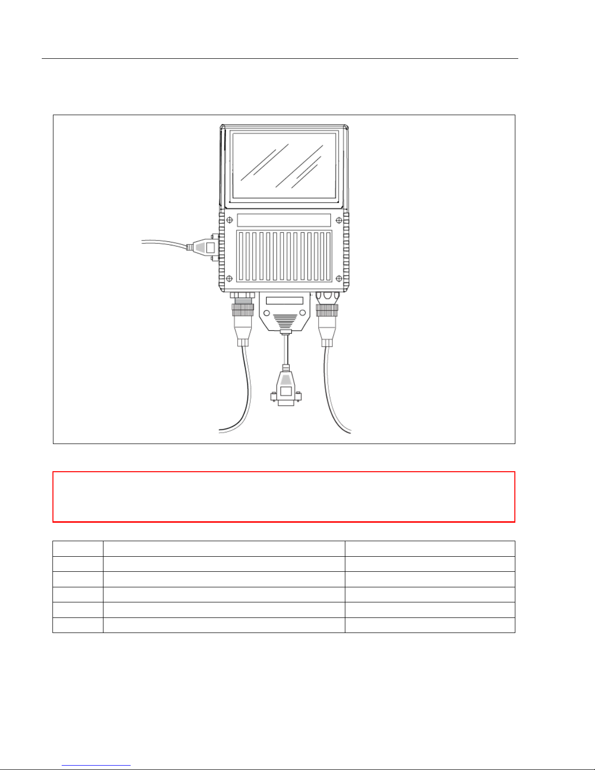
Step 1 — Check Required Hardware
Item Description Part Number
1 MS-890 Industrial Automation Scanner FIS-0890-0001G, -0002G
2 9-Pin Configuration Cable 61-000010-02
3 Power Supply 97-100004-15
4 Object Detector (optional) 99-000004-01
5 Comm./Serial Cable 61-000034-02
Note: Standalone configuration shown above.
1-2
MS-890 Industrial Automation Scanner User Manual
Page 15
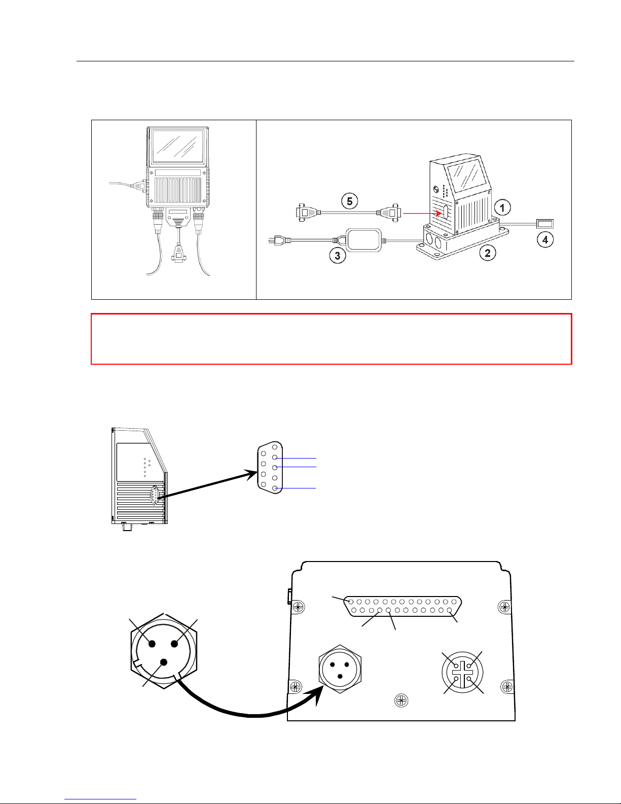
Step 2 — Connect the System
With Wiring Box
Caution: Be sure that all cables are connected BEFORE applying power to the system.
Always power down BEFORE disconnecting any cables.
Standalone
2 Receive
3 Transmit
5 Signal ground
9-pin host configuration connector
1
2
3
4
1
25
18
Power
2
3
1
Power
Ground 17
Trigger connector
Power
connector
Power +10 to 28
VDC (in)
Chassis
ground
Power
ground
25-pin host connector
Quick Start
Connecting the MS-890 Standalone
1. Attach the configuration cable to either the 9-pin (preferred) or 25-pin connector (on
bottom of unit) to configure, test, and default the scanner.
2. Attach the power supply cable to the 3-pin power connector on the bottom of the scanner.
MS-890 Industrial Automation Scanner User Manual
1-3
Page 16
Connect the System
2 Receive
3 Transmit
5 Signal ground
9-pin host configuration connector
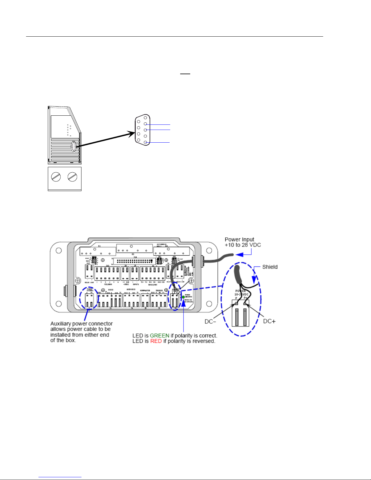
Connecting the MS-890 with Wiring Box
1. Be sure that the wiring box power cord is not plugged in.
2. Connect the scanner to the host computer.
3. Use the 9-pin configuration connector shown below to connect with your computer.
This port is useful for setting up, testing, and defaulting the scanner.
4. Connect power to the wiring box.
5. Apply power to the wiring box and confirm that the LED next to the right side power
terminal is green and not red.
6. Disconnect power.
7. Plug the ribbon cable (provided with wiring box) into the bottom of the scanner.
8. Attach the scanner to the wiring box with the 4 screws provided.
9. Power-on the scanner.
1-4
MS-890 Industrial Automation Scanner User Manual
Page 17
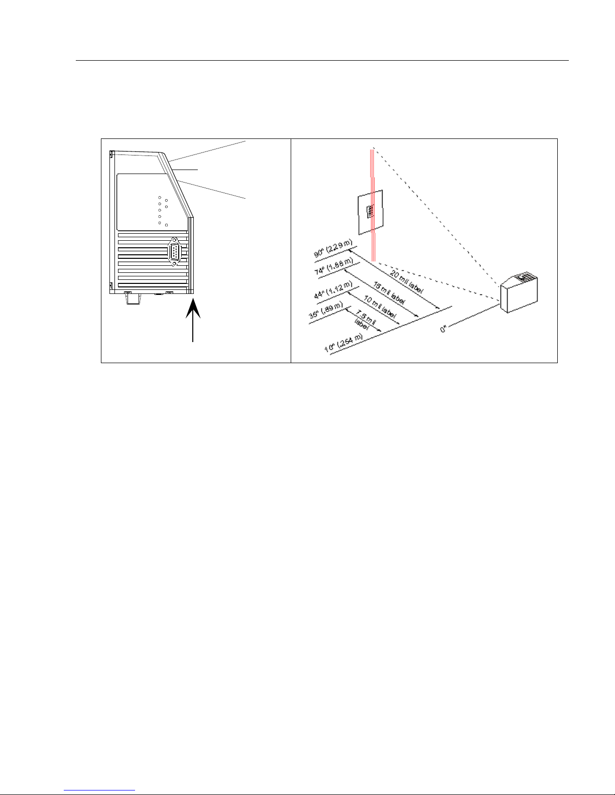
Step 3 — Position Scanner and Symbol
Centerline of
scan window
Scan Range Starts Here
Center line of
scan window
Scan range starts here
• Set up a symbol at the distance that will be used in your application.
Quick Start
Note: Code 39
is the default symbology enabled. If you are uncertain as to the symbology
type in your application, enable all symbologies by clicking the Autodiscriminate button
in EZ Mode.
Important: If using Interleaved 2 of 5 symbols in your application, verify that the number
of characters in the symbols being scanned matches the symbol length enabled for
the Interleaved 2 of 5 symbology (default is 10 and 6).
MS-890 Industrial Automation Scanner User Manual
1-5
Page 18

Install ESP
Step 4 — Install ESP
Easy Setup Program (ESP) is Microscan’s proprietary setup and testing application. The
purpose of ESP is to provide a quick and easy way to set up and configure Microscan
products.
When the MS-890 is connected to a host computer (Windows Vista, XP, or 2000), ESP
can be used to set up communication with a host, configure various firmware settings, and
control verification processes.
Important: To migrate MS-880 settings to MS-890 settings in ESP, refer to the
beginning of Chapter 2, Using ESP.
If installing from the Microscan Tools Drive:
1. Insert the Microscan Tools Drive into a USB port on your computer.
2. Choose ESP Software from the main menu.
3. Select the Current Version of ESP and follow the file download prompts.
If downloading from the Microscan website:
1. Go to http://www.microscan.com/downloadcenter
2. Create a new “myMicroscan” member account or, if you are already a member, enter
your user name and password.
3. Click the Download Software link and extract the latest version of ESP to a directory
of your choice. Note where your ESP.exe file is stored on your hard drive.
4. At the end of the installation process, the following icon will appear on your desktop:
5. Click the ESP icon to start the program.
System Requirements for ESP
•
233 MHz Pentium PC
•
Windows 8, 7, Vista, or XP operating system (32-bit or 64-bit)
• Internet Explorer 5.0 or higher
128 MB RAM or greater; 160 MB free disk space
•
• 800 x 600 256 color display (1024 x 768 32-bit color recommended)
1-6
MS-890 Industrial Automation Scanner User Manual
Page 19

Step 5 — Select Model
Note: If you need to select another model later, click the
Switch Model button near the top of the screen.
When you start ESP, this menu will appear:
Quick Start
1. Select the MS-890 from the menu and click OK. If you do not want to make this
selection every time you start ESP, uncheck “Show this dialog at startup”.
2. Click Yes when the following dialog appears:
MS-890 Industrial Automation Scanner User Manual
1-7
Page 20
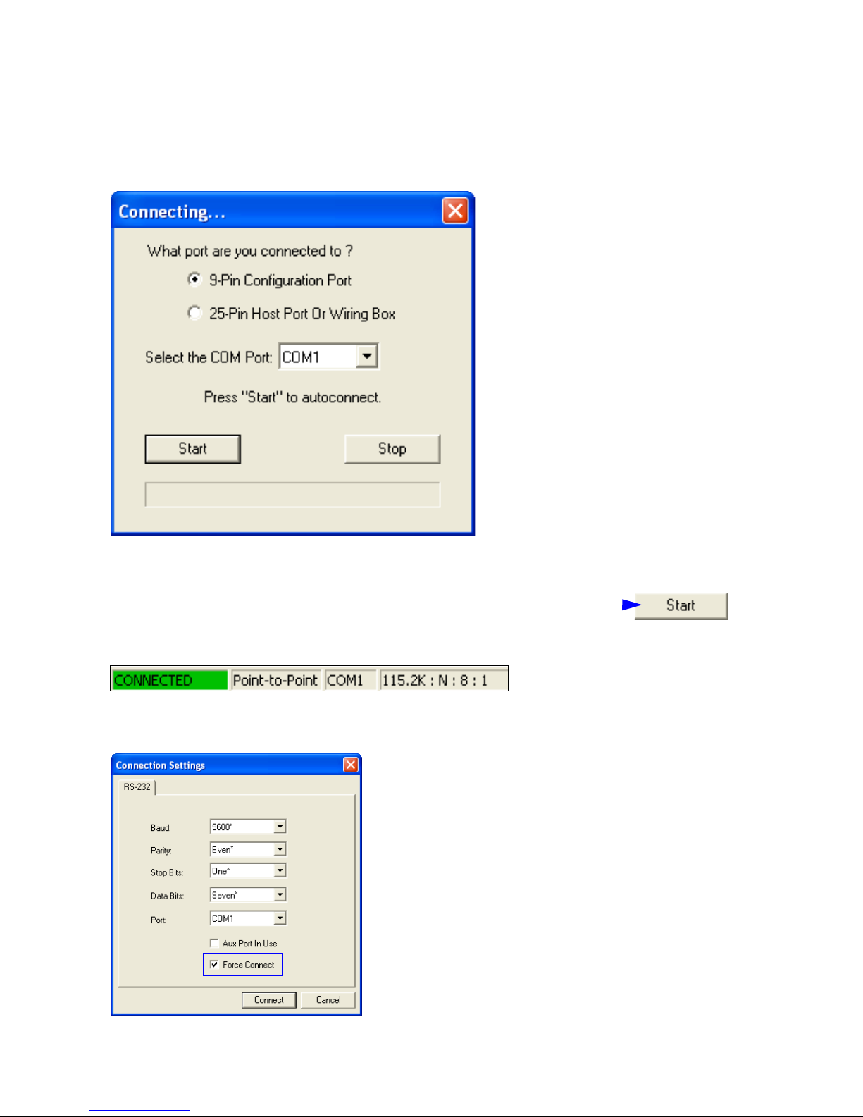
Autoconnect
Once you have chosen the correct port, click Start to connect.
When you are connected, you will see the green connection
indicator in the status bar at the bottom right of your screen:
Note: If your RS-232 host settings cannot be
changed to match the scanner’s settings, select
Connect... from the Connect menu in the menu
toolbar, and then click the Force Connect box
when you see the dialog shown at left.
Step 6 — Autoconnect
1. Select the appropriate port and click Start when the following dialog appears.
Note: If your communications port is not the default COM1, use the dropdown menu
to change your port.
2. If the connection attempt fails, click the
port, and try again.
Autoconnect
button, select a different communications
1-8
MS-890 Industrial Automation Scanner User Manual
Page 21
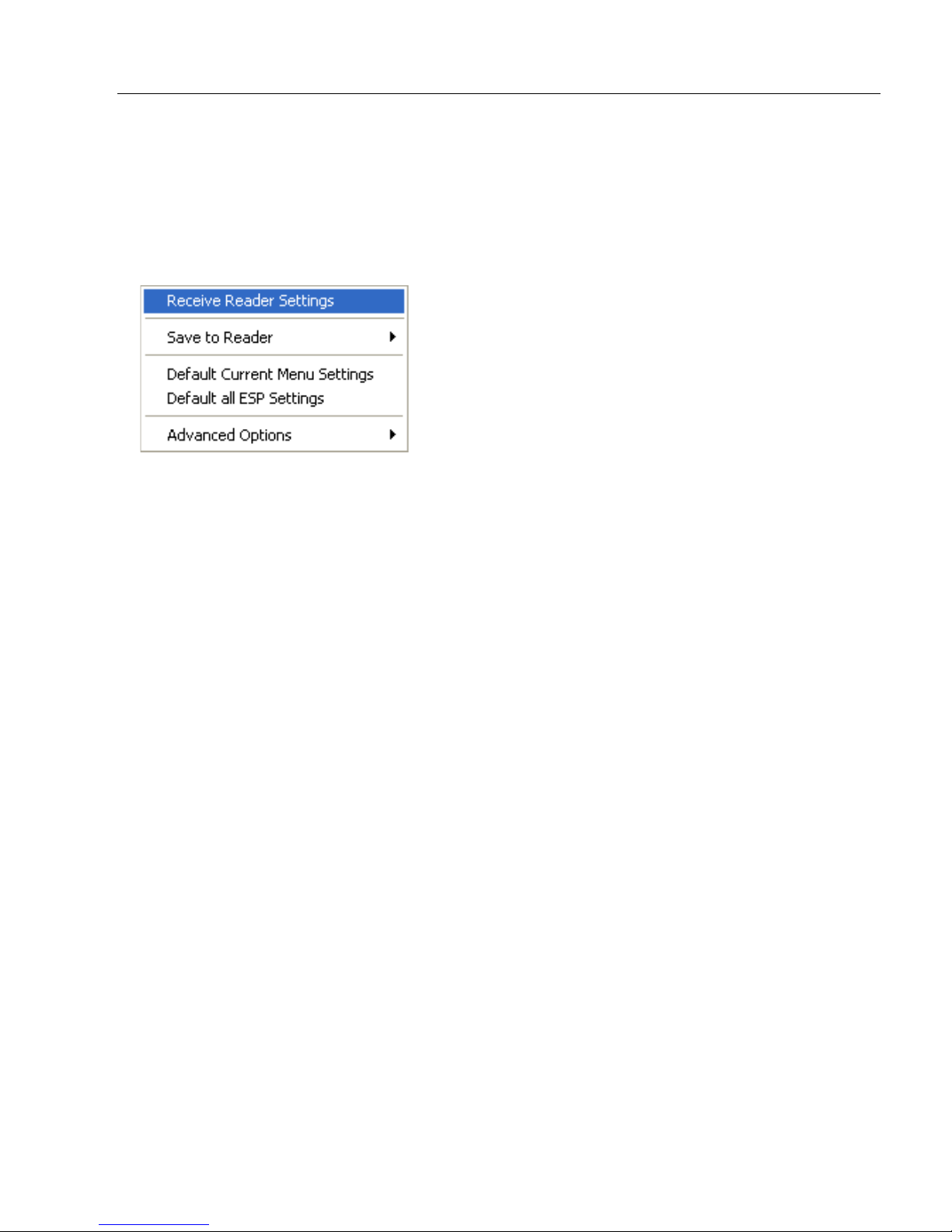
Step 7 — Receive Settings
Quick Start
To copy the scanner’s memory settings into
select Receive Reader Settings from the dropdown menu.
ESP
, right-click in the configuration
window and
Receive Reader Settings
When you select Receive Reader Settings, the settings from the scanner’s memory are
sent to ESP.
MS-890 Industrial Automation Scanner User Manual
1-9
Page 22

Calibrate
Step 8 — Calibrate
1. Click the Calibration button in EZ Mode or in the Calibration view.
2. Allow some time for the scanner to cycle through the focus, gain, and tracking settings.
Do not move or disturb the scanner or test symbol while calibration is in progress.
3. When calibration is complete, the settings that provided the highest read rate will be
selected. You will see one of the following messages: Calibration Passed, Calibration
Failed, or Original Settings Were Optimal.
Note: To silence the beeper, interrupt scanning by removing or blocking the test
symbol, or send a <K702,0> command to disable the beeper.
If calibration fails, try the following:
1. Check the read range for your particular symbol density.
2. Examine symbol quality and try a different sample symbol.
3. Slightly skew or tilt the symbol or scanner to minimize specular reflection.
4. Verify that the correct symbology is enabled.
1-10
MS-890 Industrial Automation Scanner User Manual
Page 23
Quick Start
D
e
p
t
h
o
f
f
i
e
l
d
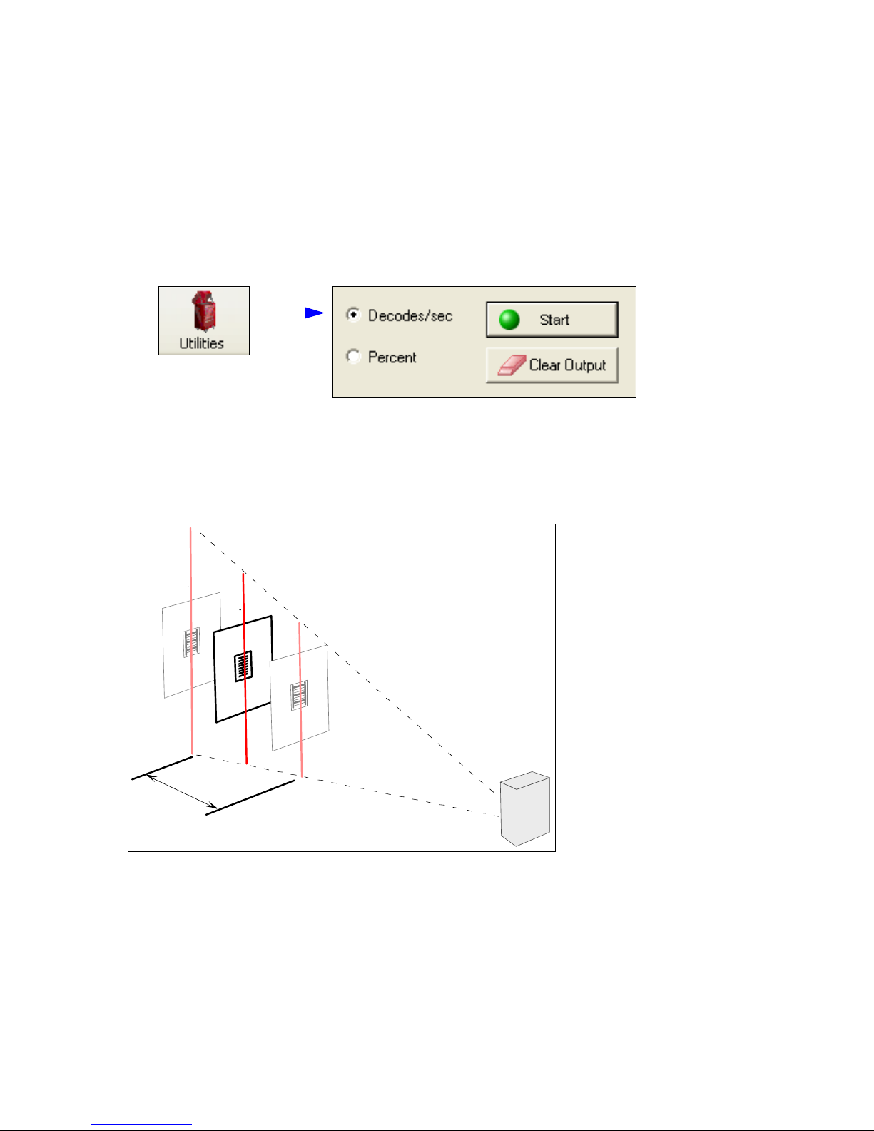
Step 9 — Test Read Rate
Important: To receive symbol data through the 9-pin configuration port, you must enable
the port with the following command: <K146,,1>.
1. Position the symbol in front of an operational MS-890 scanner.
2. Click the Utilities button.
3. Click the Start button in the Read Rate view.
If calibration has passed, the scanner sends data to the host computer and emits a beep
(if the beeper is enabled) for each good read.
Move your symbol toward the scanner and away from the scanner until the decode rates
drop off in each direction. This will give you a sense of the depth of field (inner and outer
ranges) for your symbol’s density and range.
Note:
If the scanner is in the default
routine, it will read and beep repeatedly as long as a readable symbol remains in the read
range and the read cycle configuration has not changed.
• To end the read rate test, right click Read Rate and select the Stop button.
MS-890 Industrial Automation Scanner User Manual
Continuous Read
mode and not in read rate or calibration
1-11
Page 24

Configure the Scanner in ESP
Step 10 — Configure the Scanner in ESP
To make setup changes to the MS-890, click the App Mode button.
The following modes are accessible by clicking the buttons in the first row of
• Test and Calibrate the scanner in EZ Mode.
• Establish communications between ESP and the scanner by clicking the Autoconnect
button.
• Send or receive commands by clicking the Send/Recv button.
• Switch reader models by clicking the Switch Model button.
• Click the Parameters button to make changes to tree control settings.
• Click the Setup button to adjust and test scanner settings in Calibration, Raster Setup,
Laser Framing, Configuration Database, Ordered Output, and Output Format.
• Access the Terminal, where you can view symbol data and enter serial commands.
• Review status settings or make changes to operational commands in Utilities.
App Mode
icons:
1-12
MS-890 Industrial Automation Scanner User Manual
Page 25

Step 11 — Save Configuration in ESP
1. Left click on the + to
expand the desired tree.
2. Double click on the
desired parameter and
click once in the selection
box to view options.
5. Right click on the open
screen and select Save to
Reader to implement the
command in the scanner.
4. Left click again on the
open screen to complete
your selection.
3. Place your cursor in the
selection box, scroll
down to the setting you
want to change, and
click once on the setting.
To make changes to a configuration setting:
Quick Start
Saving Options
• Send, No Save. Changes will be lost
• Send and Save. This activates all changes in current memory and saves to the scanner
for power-on.
when power is re-applied
to the scanner.
MS-890 Industrial Automation Scanner User Manual
1-13
Page 26

Save Configuration in ESP
1-14
MS-890 Industrial Automation Scanner User Manual
Page 27

2 Using ESP
Contents
EZ Mode........................................................................................................................................2-2
Application Mode...........................................................................................................................2-3
Menu Toolbar................................................................................................................................2-4
Autoconnect ................................................................................................................................2-12
View ............................................................................................................................................2-14
Navigating in ESP .......................................................................................................................2-15
Send/Receive Options ................................................................................................................2-16
This section is designed to help you understand the basic structure and elements of ESP
(Easy Setup Program).
When you open ESP, unless otherwise specified in the ESP Preferences dialog accessible
from the Options heading on the menu toolbar, you will enter EZ Mode for initial setup.
From there, you can enter Application Mode (App Mode) and access several configuration
menus (Communications, Read Cycle, Symbologies, I/O Parameters, Symbol Quality,
Matchcode, and Diagnostics), a Camera setup interface, a Termina l interface, a Utilities
interface, and an Output Format interface.
For
ESP
system requirements, see
Important: If you are switching from an MS-880 to an MS-890 in your application, follow
these steps when you open ESP:
•
With your MS-890 connected to the host computer, open your most recent MS-880
• C
onnect to the MS-890 and send all settings.
• Click the Switch Model button at the top of the ESP view. When you see the model
menu, select the MS-890.
• Receive settings.
Note: After receiving settings, you can delete the previous MS-880 model by opening
the Model dropdown menu from the menu toolbar, selecting Remove Model, and
selecting MS-880.
MS-890 Industrial Automation Scanner User Manual
System Requirements for ESP
in Chapter 1,
Quick Start
.esp
.
file.
2-1
Page 28
EZ Mode
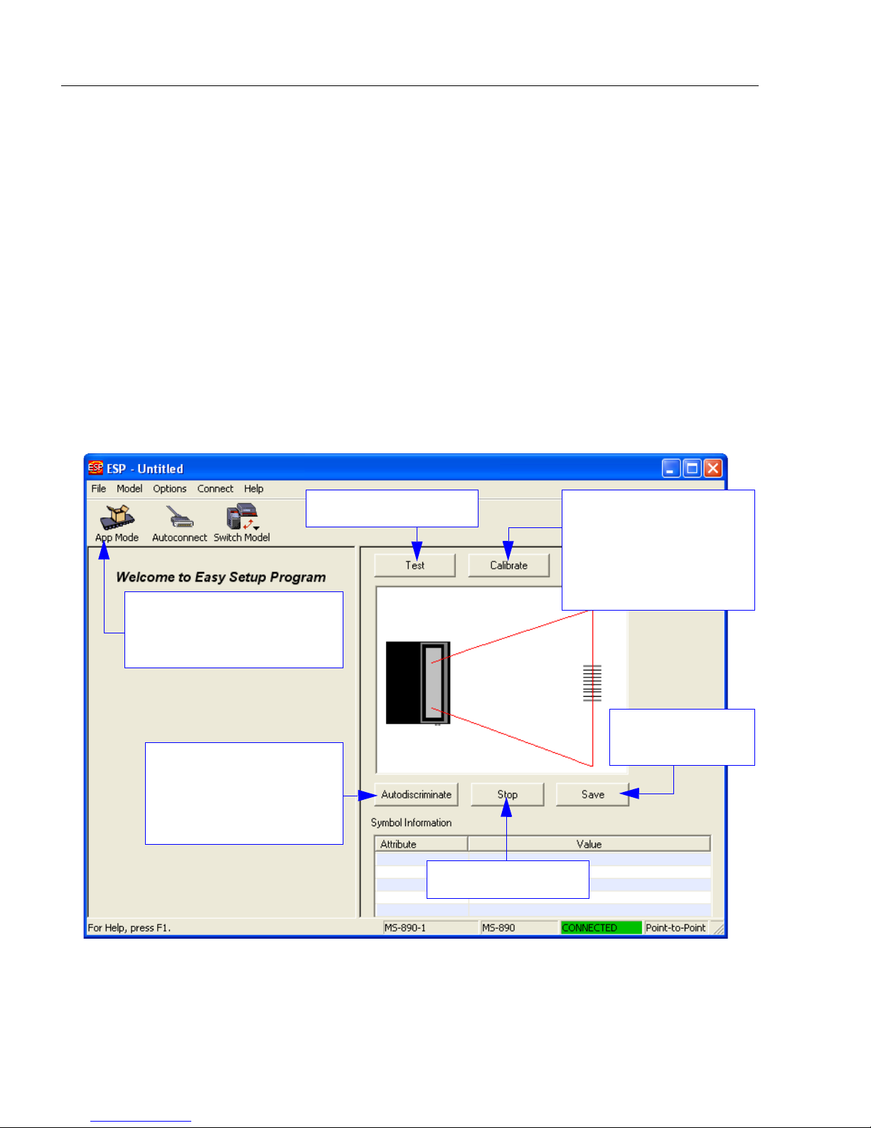
EZ Mode
In
EZ Mode
to your scanner,
instructions that will help you with positioning, testing, and calibration.
Test
Click the Test button to start the Read Rate test for a quick indication of the scanner’s read
capabilities and the limits of your application. When Decodes per Second is unchecked,
the test will count the percentage of decodes relative to the number of actual scans. Click
Stop to end the test.
Calibrate
The calibration routine that will optimize the scanner by comparing Read Rates at various
camera and image processing settings.
you are presented with the
EZ Mode
is the screen you will see. You will be provided with on-screen
Locate, Calibrate
, and
Test
options. After connecting
Enter App Mode to access
configuration trees and other
setup features.
Allows you to decode a
variety of symbologies
without stopping your
application to reconfigure
symbology settings.
Starts Read Rate test.
Ends Read Rate test.
Click Calibrate to begin
the initial calibration
routine. Calbration is
explained at the left of
the EZ Mode screen,
and also in Quick Start.
Saves Calibration
settings.
2-2
MS-890 Industrial Automation Scanner User Manual
Page 29
Using ESP
Application Mode
From EZ Mode, you can click on the App Mode button to access specific configuration
menus, Utilities tools, Camera setup, Output Format options, and a Terminal window
where serial commands can be entered.
Note: The App Mode and EZ Mode buttons appear in the same position to allow easy
switching between these primary modes.
Click this
icon to
return to
EZ Mode.
Calibration,
Raster/Laser,
Terminal,
Menu toolbar.
Click the Configuration button to return
to full App Mode view from Calibration,
Raster/Laser, Terminal, Utilities, or
Output Format.
Utilities.
Click here for
Ordered Output
and Output Format
features.
Click on icons in this row to
access configuration trees
like the one shown here.
Note: For specific information on any of the icons shown above in the operations bar or
configuration bar, see the corresponding sections of this manual.
MS-890 Industrial Automation Scanner User Manual
2-3
Page 30
Menu Toolbar
Menu Toolbar
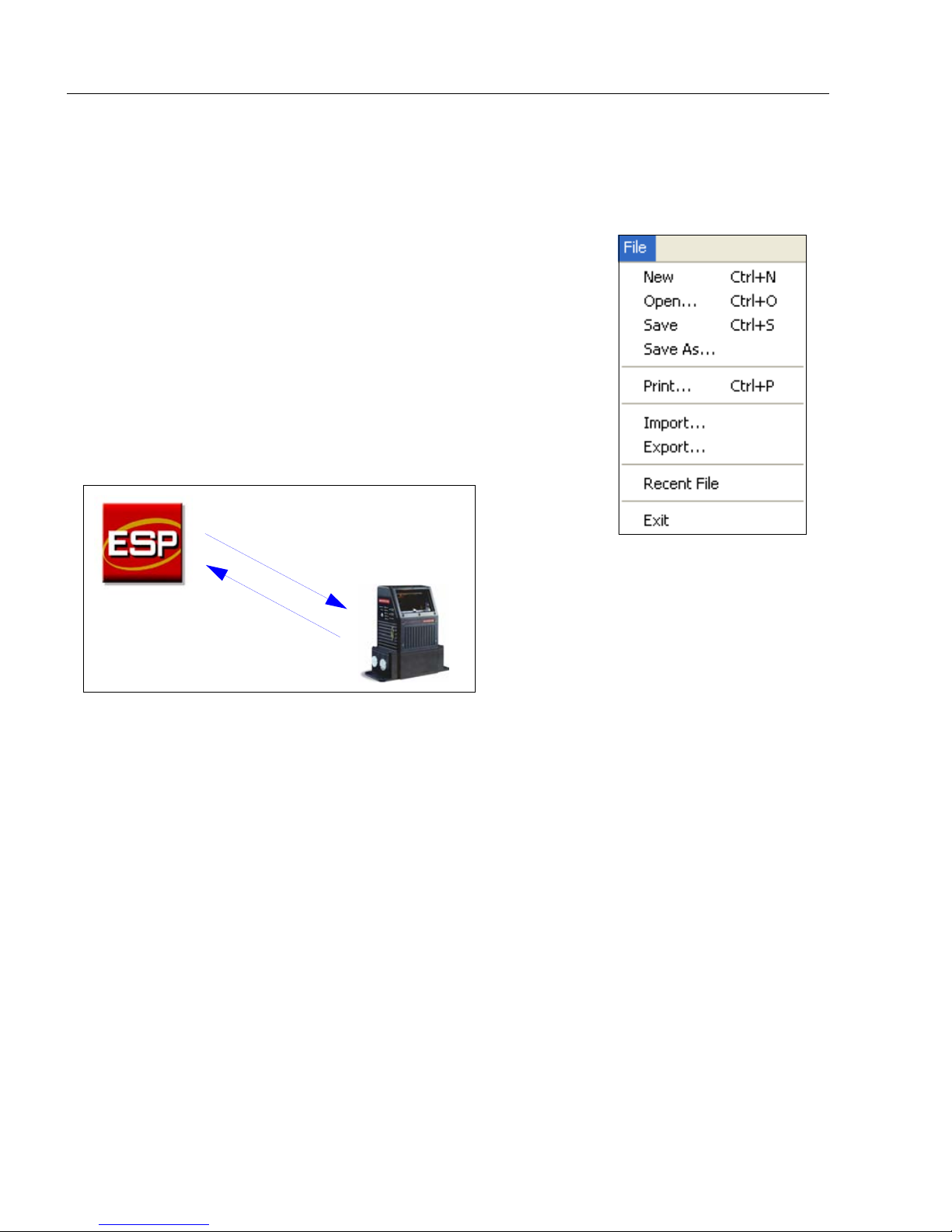
File > New
Whenever New is selected, the default configuration of ESP is
loaded.
Open/Save
When Save or Save As is selected, the ESP configuration is
saved to the host computer’s hard drive and available whenever
the same file is selected under Open.
Important: When you save menu changes to your hard drive,
these changes are not saved to your scanner. The illustration
below shows how settings can be saved and received between
ESP and the scanner, and ESP and the host hard drive.
(Save to Scanner)
(Receive Scanner
Settings)
Import/Export
Import converts the ASCII settings from a text file to ESP configuration settings.
Export converts the active ESP configuration settings to an ASCII text file.
2-4
MS-890 Industrial Automation Scanner User Manual
Page 31

Model
In Model you can select any of the models shown in
ESP’s model menu. When you
model, your current connection to
will be terminated.
To connect to another model, select New Model,
choose a new model from the menu, and click OK.
choose another
your present model
Using ESP
Note: All the models you have enabled by selecting will continue to appear in the Model
menu and that the same menu is repeated when clicking the Switch Model icon.
When you save your ESP file, you will be saving the settings of all the models defined in a
single ESP file.
MS-890 Industrial Automation Scanner User Manual
2-5
Page 32

Menu Toolbar
The Toolbar Style
options allow you to
determine how ESP
will display the mode
options in the two rows
at the top of the screen.
Options
The Options menu allows you to save memos and set up ESP
Preferences.
Note: Preferences will be saved and loaded into ESP whenever ESP
is opened next, whether or not you save the ESP file.
Preferences > General Tab
Reload Last File
At startup, reloads the last file saved to the host computer’s hard drive.
Show Model Prompt
At startup, shows the model menu displaying all supported readers.
Show Connect Prompt
At startup, displays the Would you like to connect to the MS-890? prompt.
Receive After Connect
At startup, loads the scanner’s settings into ESP. (This is not recommended if you want to
preserve your ESP settings for future use.)
Skip EZ Mode
At startup, skips EZ Mode and opens directly in App Mode.
2-6
MS-890 Industrial Automation Scanner User Manual
Page 33

Using ESP
Preferences > Terminal Tab
Show Non-Printable Characters
When Show Non-Printable Characters is enabled, characters such as “CRLF” will be
displayed in the Term inal window. When Enhanced Format is checked, the characters
are displayed with more detailed formatting.
Change Keyboard Macros
Clicking the Change Keyboard Macros button brings
up the Function Keys dialog. In this dialog you can
select the desired function key and then enter your
macro keystrokes in the associated key map. For
example, to make Ctrl-F2 the keystroke to send a trigger
character, select F2, then in the Ctrl row, enter <trigger
character> and click OK. Then whenever the Ctrl-F2
keystroke is pressed, the trigger character will start the
read cycle.
Note: The F1 key is reserved for opening ESP Help and the F3 key is reserved for the
Find Next function.
Change Font
Allows you to modify the font used for decode data received from the scanner on the
screen.
Termin al
Change Echo Font
Allows you to modify the font used for command characters typed into the Te rmin al view.
Enable Echo
Allows you to enter command characters in Terminal.
Display Incoming Data Even When Not in Focus
When Display Incoming Data Even When Not in Focus is enabled, data from the scanner
will continue to appear in the terminal even when ESP is not the top window.
MS-890 Industrial Automation Scanner User Manual
2-7
Page 34

Menu Toolbar
Preferences > Bar Code Options Tab
The Bar Code Options dialog allows you to set the size of user-created symbols.
Sizing Information
Sets the bar width or module width (in
Example: A bar width of 13 is 0.013 inches.
mils
, or thousandths of an inch) of user-created symbols.
Caption
Allows you to choose the font of human-readable captions (if symbol captions are
required), and to determine the orientation of captions in relation to symbols.
Note: Symbols can be created using the Bar Code Dialog.
2-8
MS-890 Industrial Automation Scanner User Manual
Page 35

Using ESP
Preferences > Advanced Tab
The Auto Sync options at the top of the Advanced tab allow you to determine whether
Auto Sync will be enabled automatically in sections of ESP where it is used, or if it will ask
you before it enables Auto Sync functions.
Always Ask Before Auto Sync Occurs
If you check this option box, you are then able to determine what specific Auto Sync
functions will be enabled. Receive Settings from the Reader will automatically send the
scanner’s settings to ESP when Auto Sync is enabled. Send ESP Settings to the Reader
will automatically send all scanner configuration settings chosen in ESP to the scanner.
D
o Not Send or Receive Settings
send scanner settings to ESP, or send ESP settings to the scanner.
creates a condition in which Auto Sync will not automatically
Send XON with Autoconnect
Sends an XON (Begin Transmission) command to the scanner before starting the
Autoconnect routine.
Ask to Save ESP File when Quitting
When enabled, prompts the user to save a .esp file when ending a session.
The .esp file will be saved in
the location of your choice.
MS-890 Industrial Automation Scanner User Manual
2-9
Page 36

Menu Toolbar
Preferences > Advanced Tab (cont.)
Show TCP/IP Connection Option
When enabled, shows a TCP/IP option on the Select Protocol dialog.
Note:
This option should only be selected if you intend to connect using an Ethernet adapter.
Use Default Storage Location
When enabled, automatically stores data in ESP’s Application Data folder.
2-10
MS-890 Industrial Automation Scanner User Manual
Page 37

Using ESP
Document Memo
The information you type in the Document Memo field will appear in a context-sensitive text
box whenever your cursor hovers over the Document Memo item on the Options menu.
Model Memo
Similar to Document Memo, the information you type in the Model Memo field will appear
in a context-sensitive text box whenever your cursor hovers over the Model Memo item on
the Options menu. Memos created in Model Memo are specific to the model enabled
when the message was created.
Note:
If you do not save your current session, any memos that you have entered during the session
will be discarded, and will be unavailable in your next session.
MS-890 Industrial Automation Scanner User Manual
Memos must be saved in a
.esp
file if you want them to available in your next session.
2-11
Page 38

Autoconnect
Autoconnect
• You can use Autoconnect to establish a connection between the scanner and the host.
•
If your communications port is not the default
• Once you have
chosen the correct
port, click Start to
connect.
When you are connected, you will see the green connection indicator in the status bar at
the bottom right of your screen:
COM1
, use the dropdown menu to change ports.
2-12
MS-890 Industrial Automation Scanner User Manual
Page 39

Autoconnect (cont.)
If your RS-232 host settings cannot be changed to match the scanner’s settings:
• Click Connect on ESP’s menu toolbar,
and then select Connection Wizard.
• When the Select Protocol dialog
appears, select RS-232 and click Next.
• When the RS-232 dialog appears,
check the Force Connect box and
click the Connect button.
Using ESP
MS-890 Industrial Automation Scanner User Manual
2-13
Page 40

View
View
The View menu allows you to move quickly between interfaces
without using the icon buttons on the App Mode toolbar. It also
allows you to access the Bar Code Dialog.
Bar Code Dialog
In the Bar Code Dialog you can create symbols by typing the text
you wish to encode. This is a useful tool for creating configuration
symbols, allowing you to configure your scanner by reading the
symbols you create.
Choose a spatial
orientation for the
new symbol.
Drag configuration commands
from the tree controls directly
into this field to encode new
symbols.
The symbols you create
will be displayed in the
field at the bottom of the
Bar Code Dialog.
Create a caption
for the symbol
that matches the
encoded data, or
write your own
caption.
Click the Differences from Default
Settings button to create a symbol
encoded with configuration settings
that differ from ESP defaults.
Differences from Default can be
viewed on the Differences tab in the
Utilities view.
Click Add start configuration code
and Add end configuration code;
Save Settings to add a symbol that
will enable Bar Code Configuration
mode and a symbol that will save all
new configuration settings. (Both
symbols shown at left).
See Bar Code Configuration on page A-23 for more information about configuring the
MS-890 by decoding symbols.
2-14
MS-890 Industrial Automation Scanner User Manual
Page 41

Navigating in ESP
Using ESP
To change scanner settings, or to access the
Calibration, Raster/Laser, Termin al, Utilities,
or Output Format views, click the App Mode button.
To return to EZ Mode, click the EZ Mode button.
To make changes to configuration settings in the tree controls:
The X denotes the
1. Left-click on the + to expand
menu items.
2. Double-click the desired
parameter and single-click
in the selection box to view
options.
3. Place your cursor in the
selection box, scroll down
to the setting you want to
change, and single-click
the setting.
4. Left-click again on the open screen to complete the
selection.
5. Right-click on the open screen and select Save to
Reader to implement the command in the scanner.
You can send the command without saving it, or you
can send and save the command simultaneously.
default option setting.
MS-890 Industrial Automation Scanner User Manual
2-15
Page 42

Send/Receive Options
Send/Receive Options
To a c ces s Receive, Save, and Default options, click the Send/Recv button. You can also
access these options by right-clicking in any of the configuration views.
Receiving
From the Send/Recv menu, select Receive Reader Settings.
Caution: Do not select this option if you do not want to upload the scanner’s settings. For
example, if your ESP file has a number of custom settings that you want to maintain and
download into the scanner, these settings would be lost by choosing Yes.
This is useful if you want to receive (upload) the scanner’s settings and save them as a file
for future use. For example, if your scanner has settings that you do not want to change,
choosing Yes would allow you to load those settings to ESP and save them in an ESP file
for later retrieval.
Receiving the scanner’s settings will also assure that you will not be subsequently saving
any unwanted changes that you or someone else has made previously in ESP.
Saving
Send, No Save (<A>)
Saves ESP settings to current
memory.
Send and Save (<Z>)
Activates all changes in current
memory and saves to the scanner
for power-on.
2-16
MS-890 Industrial Automation Scanner User Manual
Page 43

Using ESP
Defaulting
When you select Default Current Menu Settings or Default all ESP Settings, you are
only defaulting the ESP settings.
Advanced Options
Send Current View
This is the same as Save to Reader > Send No Save except that only the commands in
the current configuration tree are sent.
Send Current Command
This is the same as Send Current View, except that it saves only the command that is
currently selected.
Add / Remove Exception
After you perform a Receive Reader Settings command1 and you click on the Add
Exception option, you may see a list of serial commands. These are commands that may
be in your scanner’s firmware, but not included in, or different from, your current version of
You can edit these commands by double-clicking on them and changing them as needed.
It is important to note that these commands will be saved to your scanner whenever you
send a Save to Reader command, or an <A> or a <Z> command.
Also, if there is a corresponding ESP menu item, the ESP Value column for that item will
be blank following a Receive Reader Settings command.
ESP
.
1. From the Send/Recv button or by right-clicking in any blank section of a tree control view.
MS-890 Industrial Automation Scanner User Manual
2-17
Page 44

Send/Receive Options
2-18
MS-890 Industrial Automation Scanner User Manual
Page 45

Contents
Communications by ESP.............................................................................................................. 3-2
Communications Serial Commands ............................................................................................. 3-2
RS-232/422 Host Port .................................................................................................................. 3-3
Host Port Parameters................................................................................................................... 3-4
Host Protocol................................................................................................................................ 3-5
Poll Address ................................................................................................................................. 3-7
ACK / NAK Options ...................................................................................................................... 3-8
Polling Mode Options ................................................................................................................... 3-9
Auxiliary Port Protocol ................................................................................................................ 3-10
Daisy Chain Autoconfigure......................................................................................................... 3-19
Daisy Chain Scanner ID ............................................................................................................. 3-20
Auxiliary/Configuration Port System Data .................................................................................. 3-21
Preamble .................................................................................................................................... 3-22
Postamble................................................................................................................................... 3-23
LRC Status ................................................................................................................................. 3-24
Intercharacter Delay ................................................................................................................... 3-25
Response Timeout ..................................................................................................................... 3-26
3 Communications
With Microscan’s ESP (Easy Setup Program), configuration changes can be made in the
ESP menus, then sent and saved to your scanner. The user can also send serial commands
to the scanner via the ESP’s Terminal window.
This section includes connecting parameters and options for communicating by the auxiliary
port and various interfaces.
Note: When assigning characters in user-defined fields, the characters NUL, <, >, and ,
can only be entered through embedded menus, not through ESP or serial commands.
Note: Default settings for establishing communications are:
Baud = 9600
Parity = Even
Stop Bits = One
Data Bits = Seven
Flow Control = None
MS-890 Industrial Automation Scanner User Manual
3-1
Page 46

Communications by ESP
Click this button
to bring up the
Applications
menu.
Click this button
to bring up the
Communication
menu.
To open nested options,
single-click the
+.
To change a setting,
double-click the setting
and use your cursor to
scroll through the
options.
Communications by ESP
Communications Serial Commands
Command Title Command Format
Host Port Parameters <K100,baud,parity,stop bits,data bits>
Aux Port Protocol
Host Protocol <K140,protocol,address>
Preamble <K141,status,preamble character(s)>
Postamble <K142,status,postamble character(s)>
Response Timeout <K143,timeout setting>
Intercharacter Delay <K144,time interval>
LRC <K145,status>
Auxiliary/Configuration Port System Data
ACK/NAK Options <K147,RES,REQ,STX,ETX,ACK,NAK>
Polling Mode Options <K148,RES,REQ,STX,ETX,ACK,NAK>
Daisy Chain Autoconfigure <K150DAISY>
Daisy Chain Scanner ID
<K101,aux port mode,baud rate,parity,stop bits,data bits,daisy
chain ID status,daisy chain ID>
<K146,aux port status,config port status>
<
K151,
daisy chain scanner,daisy chain scanner ID>
3-2
MS-890 Industrial Automation Scanner User Manual
Page 47

Communications
RS-232/422 Host Port
Includes host port connections and host protocols.
Communications Options
You can communicate with the scanner through the following ports:
• 9-pin D-sub external connector
• Wiring box
• 25-pin D-sub external connector
Only one port can be used at a time to receive commands.
Communications with Host through the 9-pin Host Port
For the 9-pin configuration port, set the host communications settings as follows: 57.6K
baud, 8 data bits, 1 stop bits, and None parity. See Chapter 1, Quick Start, for more
information on using the 9-pin port.
Note: The 9-pin configuration port settings are not changeable.
Communications with Host through the 25-pin Port
The default 25-pin host port configuration settings are as follows: 9600, 7, 1, and Even.
Making changes to these communications parameters without corresponding changes in
linked device(s) can result in the loss of menu access. If this should occur, connect via the
9-pin port and reset your scanner’s host parameters to match the 25-pin defaults.
Communications with Host through the Wiring Box
The settings are the same as those of the 25-pin port. See Chapter 14, Wiring Box, for
details on wiring connections.
MS-890 Industrial Automation Scanner User Manual
3-3
Page 48

Host Port Parameters
Host Port Parameters
Important: This applies only to the 25-pin port and wiring box connections (not for 9-pin
port).
Note: See Communications with Host through the 9-pin Host Port on page 3-3 for 9-pin
host port parameters.
Baud Rate (Host Port)
Usage: Can be used to transfer data faster or to match host port settings.
Definition: The rate at which the scanner and host transfer data back and forth.
Serial Cmd: <K100,baud rate,parity,stop bits,data bits>
Default: 9600
Options: 0 = 600 1 = 1200 2 = 2400
3 = 4800 4 = 9600 5 = 19.2K
6 = 38.4K 7 = 57.6K 8 = 115.2K
Parity (Host Port)
Usage: Only changed if necessary to match host setting.
Definition: An error detection routine in which one data bit in each character is set to 1
or 0 so that the total number of 1 bits in the data field is even or odd.
Serial Cmd: <K100,baud rate,parity,stop bits,data bits>
Default: Even
Options: 0 = None 1 = Even 2 = Odd
Stop Bits (Host Port)
Usage: Only changed if necessary to match host setting.
Definition: One or two bits added to the end of each character to indicate the end of the
character.
Serial Cmd: <K100,baud rate,parity,stop bits,data bits>
Default: One
Options: 0 = One 1 = Two
Data Bits (Host Port)
Usage: Only changed if necessary to match host setting.
Definition: Number of bits in each character.
Serial Cmd: <K100,baud rate,parity,stop bits,data bits>
Default: Seven
Options: 0 = Seven 1 = Eight
3-4
MS-890 Industrial Automation Scanner User Manual
Page 49

Communications
Host Protocol
Usage: In general, point-to-point protocols work well in most applications. They
require no address and must use RS-232 or RS-422 communications standards.
Definition: Protocols define the sequence and format in which information is transferred
between the scanner and the host, or in the case of Polling Mode, between
scanners and a concentrator.
Important: When using Polling Mode, LRC must be Enabled and Preamble/
Postamble must be Disabled.
Serial Cmd: <K140,protocol,address>
Default: Point-to-Point
Options: 0 = Point-to-Point
1 = Point-to-Point with RTS/CTS
2 = Point-to-Point with XON/XOFF
3 = Point-to-Point with RTS/CTS and XON/XOFF
4 = ACK/NAK
5 = Polling Mode
Point-to-Point (Standard)
Usage: Used only with RS-232 or RS-422.
Definition: Standard Point-to-Point requires no address and sends data to the host
whenever it is available, without any request or handshake from the host.
Serial Cmd: <K140,0>
Point-to-Point with RTS/CTS
Usage:
Definition: Point-to-Point with RTS/CTS (request-to-send/clear-to-send) is a simple
Serial Cmd: <K140,1>
A scanner initiates a data transfer with an RTS (request-to-send) transmission.
The host, when ready, responds with a CTS (clear-to-send) and the data is
transmitted. CTS and RTS signals are transmitted over two dedicated wires
as defined in the RS-232 standard.
Used only with RS-232.
hardware handshaking protocol that allows a scanner to initiate data transfers
to the host.
MS-890 Industrial Automation Scanner User Manual
3-5
Page 50

Host Protocol
Point-to-Point with XON/XOFF
Usage: If an XOFF has been received from the host, data will not be sent to the host
until the host sends an XON. During the XOFF phase, the host is free to carry
on other tasks and accept data from other devices.
Used only with RS-232.
Definition: This option enables the host to send the XON and XOFF command as a single
byte transmission command of start (^Q) or stop (^S).
Serial Cmd: <K140,2>
Point-to-Point with RTS/CTS and XON/XOFF
Usage: Used only with RS-232.
Definition:
Serial Cmd: <K140,3>
This option is a combination of
with XON/XOFF.
Point-to-Point with RTS/CTS
and
Point-to-Point
ACK/NAK
Definition: See the ACK / NAK Options command <K147> on page 3-8.
Serial Cmd: <K140,4>
Polling Mode
Definition: See the Polling Mode Options command <K148> on page 3-9.
Serial Cmd: <K140,5>
3-6
MS-890 Industrial Automation Scanner User Manual
Page 51

Poll Address
Serial Cmd: <K140,protocol,address>
Default: 1
Options: 1 to 50
1 = Poll address 0x1C, Select address 0x1D
2 = Poll address 0x1E, Select address 0x1F
...
50 = Poll address 0x7E, Select address 0x7F
Communications
MS-890 Industrial Automation Scanner User Manual
3-7
Page 52

ACK / NAK Options
ACK / NAK Options
Definition:
Serial Cmd: <K147,RES,REQ,STX,ETX,ACK,NAK>
These parameters take effect for
RS-422 ports (not on the Auxiliary Port), and are completely independent of
the
Polling Mode Options <K148>
The scanner always follows the protocol in both directions (to and from the
host). There is no option to disable it from either direction.
ACK/NAK <K140,4>
.
on the main RS-232 or
RES-NAK Defaults
RES: (Reset) 0x00 (disabled)
REQ: (Request) 0x00 (disabled)
STX: (Start of Text) 0x00 (disabled)
ETX: (End of Text) 0x00 (disabled)
ACK: (Acknowledge) 0x06
NAK: (Negative Acknowledge) 0x15
The following are general outlines of the ACK/NAK protocol. Items that are framed by
brackets ( [ ] ) can either be disabled or enabled. LRC does not include STX, but it does
include preamble, postamble, and ETX.
Symbol Data Output
TX to host: [STX] [preamble] SYMBOL DATA [postamble] [ETX] [LRC]
Response from host: ACK/NAK. Sent when LRC, ETX, postamble, or timeout (waiting
for more data) are detected (if REQ is disabled) depending on what is enabled.
Commands from Host to Scanner
TX to Scanner: [STX] <command> [ETX] [LRC]
Response from Scanner: ACK/NAK. Sent when LRC, ETX, or command-ending angle
bracket ‘>’ are received, depending on what is enabled.
Command Response from Scanner to Host
TX to host: [STX] [preamble] COMMAND RESPONSE DATA [postamble] [ETX] [LRC]
Response from host: ACK/NAK. Sent when LRC, ETX, postamble, command-ending
angle bracket ‘>’, or timeout (waiting for more data) are detected, depending on what is
enabled.
As with Polling Mode <K140,5>, the scanner can optionally perform the REQ and RES
event sequences in ACK/NAK mode. If the sender does not receive an ACK or NAK, it will
send REQ to request such a response (if enabled). When the sender receives an ACK, too
many NAKs, or times out (if already enabled), it will send a RES (if enabled) to terminate the
transaction.
3-8
MS-890 Industrial Automation Scanner User Manual
Page 53

Communications
Polling Mode Options
Definition: These parameters only take effect for Polling Mode <K140,5> on the main
RS-232 or RS-422 ports (not on the Auxiliary Port), and are completely
independent of the ACK/NAK Options <K147>.
The values of protocol characters can be changed, but the protocol events
cannot be disabled. The polling mode address is configured in the <K140>
command (see Poll Address on page 3-7).
Serial Cmd: <K148,RES,REQ,STX,ETX,ACK,NAK>
RES-NAK Defaults
RES: (Reset) 0x04 (disabled)
REQ: (Request) 0x05 (disabled)
STX: (Start of Text) 0x02 (disabled)
ETX: (End of Text) 0x03 (disabled)
ACK: (Acknowledge) 0x06
NAK: (Negative Acknowledge) 0x15
MS-890 Industrial Automation Scanner User Manual
3-9
Page 54

Auxiliary Port Protocol
Auxiliary Port Protocol
Note: The Aux Port cannot be used when the host port is set to RS-422 or Multidrop.
As with the host port parameters, the auxiliary terminal’s settings (baud rate, parity, stop
bits, and data bits) must be identical with those of the auxiliary device.
Usage: These commands set the communication parameters with the auxiliary port
which can be used to configure menus, send data to the host, display data
transmissions originating from the host of the scanner, and relay data from
other scanners set in tandem (Daisy-Chained). If the scanner’s host port
needs to be dedicated to the host, but configuration must be done on the fly,
the auxiliary port can be set to accept configuration changes by Command
Processing.
Definition:
An auxiliary port connects the scanner to a remote display or to other scanners
that can display or transfer data. As with the host port parameters, the auxiliary
terminal’s settings (baud rate, parity, stop bits, and data bits) must be identical
to those of the auxiliary device.
Aux Port Mode
Note: The Aux Port interacts only with the host port via the 25-pin port except when in
Daisy Chain mode. When in Daisy Chain mode, the Aux Port will also interact with the
configuration port (9-pin port) or the wiring box network ports.
Definition: Determines the flow of data between the auxiliary port device(s), the scanner,
and the host.
<
Serial Cmd:
Default: Disabled
Options: 0 = Disabled
K101,aux port mode
daisy chain ID>
1 = Transparent
2 = Half Duplex
3 = Full Duplex
4 = Daisy Chain
5 = Command Processing
,baud rate,parity,stop bits,data bits,daisy chain ID status,
3-10
MS-890 Industrial Automation Scanner User Manual
Page 55

Transparent (Aux Port Mode)
Host
Aux.
Port
Scanner
Host
Aux.
Port
Scanner
Host
Aux.
Port
Scanner
Communications
Usage:
Often used in conjunction with handheld scanners. Employs an auxiliary readout
to detect mis-applied symbols.
Definition: In Transparent mode data is passed between the auxiliary port and the host.
The scanner buffers data from the auxiliary port and echoes the keyed data
on the auxiliary port.
Data Initiated from the Auxiliary Port
Auxiliary port data is passed through to the host
whenever a return key is pressed at the auxiliary
port or symbol data is sent.
Whenever Aux Port data is sent with symbol
data, the Aux Port data will appear between the
preamble and the symbol data.
Auxiliary port data to the host is always sent with a
preamble and a postamble.
If the scanner is in a polled mode to the host,
auxiliary port data will still pass through.
<D> is the only command accepted by the scanner from the auxiliary port. All
other commands will pass through to the host.
Data Initiated from the Scanner
Transmission to the auxiliary port occurs immediately
upon a good read.
Scan data to the auxiliary port does not include a
preamble or a postamble.
Communications with the auxiliary port is always in
Point-to-Point protocol, even if the host is in a
polled protocol mode.
Data Initiated from the Host
All host data is echoed to the auxiliary port in
unpolled and polled mode.
Serial Cmd:
<
K101,aux port mode
daisy chain ID>
1 = Transparent
MS-890 Industrial Automation Scanner User Manual
,baud rate,parity,stop bits,data bits,daisy chain ID status,
3-11
Page 56

Auxiliary Port Protocol
Host
Aux.
Port
Scanner
Host
Aux.
Port
Scanner
Host
Aux.
Port
Scanner
Half Duplex (Aux Port Mode)
Usage: Used to display symbol data on an auxiliary screen close to the scanner.
Definition: In Half Duplex mode all auxiliary port data and symbol data is sent directly to
the host. Symbol data is displayed on the auxiliary port screen at the same
time the data is sent to the host.
Data Initiated from the Auxiliary Port
Auxiliary port data to the host is ignored if the scanner
is in a polled mode.
Auxiliary port data or scanned data is sent to the
host whenever it is received.
Auxiliary port data is not echoed.
Auxiliary port data to the host is always sent without a
preamble or a postamble.
<D> is the only command that is accepted by the
scanner from the auxiliary port. All other commands
are passed through to the host.
Data Initiated from the Scanner
Scan data is transmitted to the auxiliary port at the
same time it is transmitted to the host.
Data transmission conforms with all parameters
specified in the configuration menu (e.g., Preamble,
Postamble, End of Read Cycle).
Serial Cmd:
Data Initiated from the Host
All host data is echoed to the auxiliary port in
unpolled mode.
<
K101,aux port mode
,baud rate,parity,stop bits,data bits,daisy chain ID status,
daisy chain ID>
2 = Half Duplex
3-12
MS-890 Industrial Automation Scanner User Manual
Page 57

Communications
Host
Aux.
Port
Scanner
Host
Aux.
Port
Scanner
Host
Aux.
Port
Scanner
Full Duplex (Aux Port Mode)
Usage: Used when communication to and from the auxiliary port is required.
Definition: In Full Duplex mode all auxiliary port data and symbol data is sent directly to
the host. Symbol data is not displayed on the auxiliary port screen.
Data Initiated from the Auxiliary Port
Auxiliary port data to the host is ignored if the
scanner is in a polled mode.
Auxiliary port data or scanned data is sent to the
host whenever it is received.
Auxiliary port data is not echoed.
Auxiliary port data to the host is always sent
without a preamble or a postamble.
<D> is the only command that is accepted by the
scanner from the auxiliary port. All other commands
are passed through to the host.
Data Initiated from the Scanner
Scan data is not sent to the auxiliary port.
Data Initiated from the Host
All host data is echoed to the auxiliary port in
unpolled mode.
<
Serial Cmd:
K101,aux port mode
daisy chain ID>
3 = Full duplex
MS-890 Industrial Automation Scanner User Manual
,baud rate,parity,stop bits,data bits,daisy chain ID status,
3-13
Page 58

Auxiliary Port Protocol
Daisy Chain (Aux Port Mode)
Note: See also Daisy Chain Autoconfigure on page 3-19.
Usage: Used in applications where:
A symbol might be scanned in both ladder and picket fence directions.
A symbol may be present on multiple sides of a package.
Symbols are presented at different depths.
Definition: In a daisy chain application, scanners are connected in series or “daisy chain”
and decoded data is relayed from one scanner to another on up to the host.
A master scanner has its host port linked to the host computer and its auxiliary
port linked to the host port of the first secondary scanner in the chain. Thereafter,
each secondary’s auxiliary port is linked to the host port of the secondary that is
further from the host in the daisy chain.
Each scanner in the daisy chain can be assigned an ID that accompanies any
data that it sends.
<
Serial Cmd:
K101,aux port mode
daisy chain ID>
4 = Daisy Chain
Function: Before the master scanner times out, it checks its auxiliary port for data. It
should be set to wait at least 20 ms for each secondary in the daisy chain.
(See Read Cycle Timeout on page 4-16.) If no data is received within the
read cycle timeout, the master sends a No Read message to the host. Otherwise
the complete data is sent.
If for example the master scanner is set to timeout in 120 ms, the first secondary
scanner downstream might be set to 100 ms, the next to 80 ms, and so forth,
thus assuring that at least 20 ms elapses between transmissions.
Daisy-chained scanners can send a series of symbols by enabling
and a common multisymbol separator. If the master scanner does not receive
the expected number of symbols, No Read messages are appended to the
data string to make up the difference between the number of symbols
enabled in Multisymbol and the number of symbols read.
For example, a master and two secondary scanners have
set to 3 and Multisymbol Separator defined as %. If the master and the first
secondary scanner do not find symbols, but the next secondary scanner
registers a good read, the transmitted results would be:
,baud rate,parity,stop bits,data bits,daisy chain ID status,
a
Multisymbol
Number of Symbols
symbol data % No Read % No Read
a. The above example is based on the best case. Other factors such as baud rate, dynamic
focus timing, number of characters in a given symbol, and the number of secondaries in the
daisy chain can affect timing and may need to be included in your calculations for complete
accuracy.
3-14
MS-890 Industrial Automation Scanner User Manual
Page 59

Communications
Daisy Chain (Aux Port Mode) (cont.)
Conditions: The conditions for a daisy chain application are as follows:
1. The master scanner’s trigger must be Serial or External; the secondary
scanners’ triggers are configured for Serial.
2. All scanners are enabled to Daisy Chain mode.
3. Each scanner’s auxiliary port must be connected to the Host port of its
secondary scanner.
4. Each secondary scanner in the daisy chain must be set to send its
data no less than 20ms before its preceding scanner.
5. All but the master scanner must have Postamble enabled and set to
CR (^M) only.
6. All but the master scanner must have their No Read messages disabled.
7. If Multisymbol is enabled, Multisymbol Separator characters must
match in all scanners and Number of Symbols must be set to number
large enough to include all the symbols it may itself read plus the
number of symbols that it will be expected to relay to the host or the
next scanner up the line.
8. Symbology ID enable/disable must be the same in all scanners.
9. All but the master scanner must have their diagnostic warning messages
disabled.
10. Daisy Chain ID Status enable/disable and the number of characters
in Daisy Chain ID must be the same in all scanners.
MS-890 Industrial Automation Scanner User Manual
3-15
Page 60

Auxiliary Port Protocol
Command Processing (Aux Port Mode)
Usage: Allows user to send configuration from the Host port or the Aux Port.
Definition: When enabled, Command Processing allows commands to be entered via
the Aux Port. The following rules apply:
• Symbol data, including the serial trigger if used, will be transmitted to the
last port from which a command was sent.
• If a reset occurs, all data will be transmitted to the host port.
Serial Cmd:
<
K101,aux port mode
,baud rate,parity,stop bits,data bits,daisy chain ID status,
daisy chain ID>
Options: 5 = Command Processing
3-16
MS-890 Industrial Automation Scanner User Manual
Page 61

Communications
Baud Rate (Aux Port)
Usage: Can be used to transfer data faster or match an auxiliary device.
Definition: The rate at which the scanner and host transfer data back and forth.
Serial Cmd:
Default: 9600
Options: 1 = 1200
<
K101,
daisy chain ID>
2 = 2400
3 = 4800
4 = 9600
5 = 19.2K
6 = 38.4K
7 = 57.6K
8 = 115.2K
aux port mode,
baud rate
,parity,stop bits,data bits,daisy chain ID status,
Parity (Aux Port)
Usage: Only changed if necessary to match host setting.
Definition: An error detection routine in which one data bit in each character is set to 1 or
0 so that the total number of 1 bits in the data field is even or odd.
<
Serial Cmd:
Default: Even
K101,
daisy chain ID>
aux port mode,baud rate,
parity
,stop bits,data bits,daisy chain ID status,
Options: 0 = None 1 = Even 2 = Odd
Stop Bits (Aux Port)
Usage: Only changed if necessary to match host setting.
Definition: Allows the user to select the last one or two bits in each character to indicate
the end of the character.
Serial Cmd:
Default: One
Options: 0 = One 1 = Two
MS-890 Industrial Automation Scanner User Manual
<
K101,
daisy chain ID>
aux port mode,baud rate,parity,
stop bits
,data bits,daisy chain ID status,
3-17
Page 62

Auxiliary Port Protocol
Data Bits (Aux Port)
Usage: Only changed if necessary to match host setting.
Definition: Number of bits in each character.
<
Serial Cmd:
Default: Seven
Options: 0 = Seven 1 = Eight
K101,
daisy chain ID>
aux port mode,baud rate,parity,stop bits,
data bits
,daisy chain ID status,
Daisy Chain ID Status (Aux Port)
Note: Enable/disable and length must be the same in all scanners.
Usage: Used in a daisy chain setup in cases where the host needs to know which
scanner in a daisy chain setup sent the data.
Definition: Each scanner in a daisy chain can be assigned a one or two character ID that
will appear in front of decoded data and identify its source.
Serial Cmd:
Default: Disabled
Options: 0 = Disabled 1 = Enabled
<
K101,
daisy chain ID>
aux port mode,baud rate,parity,stop bits,data bits,
daisy chain ID status,
Daisy Chain ID (Aux Port)
Note: All secondary scanners must be set to Serial for Daisy Chain to function.
See Trigger on page 4-5.
Usage: Used in a daisy chain setup in cases where the host needs to know which
scanner sent the data.
Definition: A one or two character prefix which identifies the particular daisy chain scanner
from which the data is being sent.
Serial Cmd: <K101,aux port mode,baud rate,parity,stop bits,data bits,daisy chain ID status,
daisy chain ID>
Default: 1/
Options: Any one or two ASCII characters.
3-18
MS-890 Industrial Automation Scanner User Manual
Page 63

Communications
Host
Primary
Scanner
Secondary
Scanner
Secondary
Scanner
SS S
Host
Primary
Scanner
Secondary
Scanner
Secondary
Scanner
ESS
Daisy Chain Autoconfigure
Note: This command is not available in ESP.
Usage: For quick setup and configuration of the daisy chain network.
Definition: Daisy Chain Autoconfigure is issued to the master scanner in the daisy
chain and the software responds as follows:
• Counts the number of secondary scanners in the daisy chain.
• Assigns an internal ID number (1...n) to each secondary scanner, where
the first secondary scanner is number 1 (and its own ID being a 0).
• Propagates the communications settings and the relevant operating
modes of the master scanner to the host and auxiliary ports of each
secondary scanner.
• Resets each secondary scanner.
• Verifies that each secondary scanner has acquired the new settings.
Serial Cmd: <K150DAISY>
When setting up a daisy chain operation, follow these steps:
1. Set the master (the scanner connected to the host) scanner to Serial.
This sets all the scanners in the daisy chain to
Serial
when the command is carried out.
Before Autoconfigure you must set the primary scanner to Serial (S):
2. Send <K150DAISY> command.
3. If necessary, set the master scanner to Edge.
After Autoconfigure you may set the primary scanner to Edge (S), but the other
scanners must remain in Serial (S):
MS-890 Industrial Automation Scanner User Manual
3-19
Page 64

Daisy Chain Scanner ID
Daisy Chain Scanner ID
Note: Scanner IDs can also be assigned in Daisy Chain (Aux Port Mode) (page 3-14).
Usage: This command provides a convenient way to assign custom daisy chain IDs
to specific scanners that were assigned during the daisy chain autoconfigure
process.
Definition:
Assigns a new daisy chain ID to a daisy chain secondary scanner. The command
is sent to the master scanner to configure the other secondary scanners.
Scanner Number
Definition: Specifies the target scanner (by sequential number) which will be receiving
the new daisy chain ID. The master scanner is always 0 (zero). All secondary
scanners are numbered 1...n in the order that they are connected.
Note: These numbers are for assigning IDs only and are not
changeable.
Serial Cmd: <K151,daisy chain scanner #,daisy chain scanner ID>
Options: 1....n (0 for the master scanner)
Scanner ID
Definition: A two-character user-defined ASCII message identifying a scanner in the
daisy chain.
Serial Cmd: <K151,daisy chain scanner #,scanner ID>
Default: Sequential numbering of scanner units resulting from the Daisy Chain
Autoconfigure <K150DAISY> command; for example: ID Master = 1/;
ID Scanner 1 = 2/; ID Scanner 2 = 3/; etc.
Options: Any two characters except NUL, <, >, or ,.
Note: See also Chapter 13, Output Format.
Note: After a secondary scanner accepts a new ID, it automatically invokes a
reset-with-save command.
3-20
MS-890 Industrial Automation Scanner User Manual
Page 65

Communications
Auxiliary/Configuration Port System Data
Note: Do not use Auxiliary Port in a daisy chain operation.
Auxiliary Port Status
Note: This command only applies if Auxiliary Port Mode is set to Command Processing.
See Command Processing (Aux Port Mode) on page 3-16.
Usage: To check symbol data and error messages via the Aux Port.
Definition: When enabled, system data, including decoded data and diagnostic warning
messages, will be routed to the Aux Port.
Serial Cmd: <K146,aux port status,config port status>
Default: Disabled
Options: 0 = Disabled 1 = Enabled
Configuration Port Status
Usage: To check symbol data and error messages via the configuration port.
Definition: When enabled, system data, including decoded data and diagnostic warning
messages, will be routed to the 9-pin configuration port.
Serial Cmd: <K146,aux port status,config port status>
Default: Enabled
Options: 0 = Disabled
1 = Enabled
Important: Enable Data Out 9-Pin when using the configuration port.
MS-890 Industrial Automation Scanner User Manual
3-21
Page 66

Preamble
Preamble
Preamble Status
Usage: Used for identifying and controlling incoming data. For example, defining the
preamble as a carriage return and a line feed causes each decoded message
to be displayed on its own line.
Definition: Defines a one to four character data string that can be added to the front of
the decoded data.
Serial Cmd: <K141,status,preamble character(s)>
Default: Disabled
Options: 0 = Disabled 1 = Enabled (within any protocol)
Preamble Character(s)
Serial Cmd: <K141,status,preamble character(s)>
Default: ^M corresponds to: carriage return/NUL/NUL/NUL.
Options: Up to four user-defined ASCII characters, including control characters.
Within a Serial Command
To enter control characters within a serial command, hold down the control
key while typing the desired character.
Example: <K141,1,CTRL-m> to enter ^M
Within an Embedded Menu
Control characters entered on the command line are displayed in the menu
as mnemonic characters, such as: <CR><NUL><NUL><NUL>.
To enter a control character from within an embedded menu, first type in a
space (with the space key). This has the effect of allowing the control key to
be recognized as a part of the control character. Next hold down the control
key while typing the desired character.
Example: Space CTRL-m to enter ^M
3-22
MS-890 Industrial Automation Scanner User Manual
Page 67

Communications
Postamble
Postamble Status
Usage: Used for identifying and controlling incoming data. For example, defining the
postamble as a carriage return and a line feed causes each decoded message
to be displayed on its own line.
Definition: Defines a one- to four-character data string that can be added to the end of
the decoded data.
Serial Cmd: <K142,status,postamble character(s)>
Default: Enabled
Options: 0 = Disabled 1 = Enabled
Postamble Character(s)
Serial Cmd: <K142,status,postamble character(s)>
Default: ^M^J corresponds to carriage return/line feed/NUL/NUL, as displayed in
the menu.
Options: Up to four user-defined ASCII characters, including control characters.
Within a Serial Command
To enter control characters within a serial command, hold down the control
key while typing the desired character.
Example: <K142,1,CTRL-m CTRL-j> to enter ^M^J.
Within an Embedded Menu
Control characters entered on the command line are displayed in the menu
as mnemonic characters, such as: <CR><LF><NUL><NUL>
To enter a control character from within an embedded menu, first type in a
space (with the space key). This has the effect of allowing the control key
be recognized as a part of the control character. Next hold down the control
while typing the desired character.
Example: Space CTRL-m Space CTRL-j to enter ^M^J.
to
key
MS-890 Industrial Automation Scanner User Manual
3-23
Page 68

LRC Status
LRC Status
(Longitudinal Redundancy Check)
Usage: Used when extra data integrity is required.
Definition: An error-checking routine that verifies the accuracy of transmissions. It is the
exclusive OR of all characters following the STX (start of text) up to and
including the
all the characters in a transmissions are cumulatively added in a column and
each resulting odd integer is assigned a 1 and each even integer a 0 (two 1s
= 0, two 0s = 0, a 1 and a 0 = 1). The extra LRC character is then appended
to the transmission and the receiver connected to the host port performs the
same addition and compares the results.
Serial Cmd: <K145,status>
Default: Disabled
Options: 0 = Disabled 1 = Enabled
ETX
(end of text). What this means is that the binary representation
of
3-24
MS-890 Industrial Automation Scanner User Manual
Page 69

Communications
Intercharacter Delay
Usage: Used only when a host cannot receive data quickly enough and there is
enough time between symbols to allow data to be completely transferred.
rarely used since any setting other than zero will slow down communications.
example, a 200 setting will result in a 1/5 second delay between each character
that is transmitted.
Definition: The time interval in milliseconds between individual characters transmitted
from the scanner to the host.
Serial Cmd: <K144,intercharacter delay>
Default: 0
Options: 0 to 255 (in milliseconds)
Note: 0 causes no delay between characters.
It is
For
MS-890 Industrial Automation Scanner User Manual
3-25
Page 70

Response Timeout
Response Timeout
Usage: Used only when a response is required from the host. While in Multidrop, if
the scanner does not receive an ACK or NAK from the host after sending
polled data, it will act on a fault. The scanner can be set to wait indefinitely by
setting Response Timeout to zero.
Definition: Time the scanner will wait before timing out if ACK, NAK, and ETX are
enabled, and a host response is expected.
Serial Cmd: <K143,response timeout>
Default: 2 (x 10 = 20 ms)
Options: 0 to 255 in 10 ms increments (0 to 2.55 seconds)
(A 0 setting causes an indefinite wait.)
3-26
MS-890 Industrial Automation Scanner User Manual
Page 71

4 Read Cycle
Contents
Read Cycle by ESP...................................................................................................................... 4-2
Read Cycle Serial Commands ..................................................................................................... 4-2
Multisymbol................................................................................................................................... 4-3
Trigger .......................................................................................................................................... 4-5
External Trigger State................................................................................................................. 4-11
Serial Trigger.............................................................................................................................. 4-12
Start Character (Non-Delimited).................................................................................................4-13
Stop Character (Non-Delimited) ................................................................................................. 4-13
End of Read Cycle...................................................................................................................... 4-14
Good Decode Reads.................................................................................................................. 4-17
Gain Settings.............................................................................................................................. 4-18
Focus.......................................................................................................................................... 4-19
Scan Speed................................................................................................................................ 4-20
Automatic Gain Control (AGC) Settings..................................................................................... 4-21
Maximum Element...................................................................................................................... 4-22
Tracking Adjustment................................................................................................................... 4-23
After you’ve established communications and completed basic read rate testing, you will
need to address the spatial and timing parameters associated with your application. In a
typical operation, a bar-coded item moves along a line past a scanner. A trigger or timer
activates a read cycle during which the scanner actively searches for symbols. You will
need to decide how to initiate the read cycle and how and when to end it.
Note: When assigning characters in user-defined fields, the characters NUL, <, >, and ,
can only be entered through embedded menus, not through ESP or serial commands.
Note: You can learn the current setting of any parameter by inserting a question mark after
the number, as in <K100?>. To see all K commands, send <K?>.
Note on Serial Commands: To preserve continuity with other Microscan products, some
serial configuration commands may include 0s or 1s as placeholders. In order for a these
commands to be implemented, the parameter values or a comma must be included.
MS-890 Industrial Automation Scanner User Manual
4-1
Page 72

Read Cycle by ESP
Read Cycle by ESP
Click this button to
bring up the Read
Cycle menu.
To change a setting,
double-click the
setting and use your
cursor to scroll
through the options.
To open nested options, single-click the +.
Read Cycle Serial Commands
Command Title Command Format
Trigger <K200,trigger mode,trigger filter duration>
Serial Trigger Character <K201,trigger character>
External Trigger State <K202,external trigger state>
End of Read Cycle <K220,end of read cycle mode,read cycle timeout>
Good Decode Reads <K221,number before output,mode>
Multisymbol <K222,number of symbols,multisymbol separator>
Start Serial Trigger Character <K229,start trigger character>
End Serial Trigger Character <K230,end trigger character>
Scan Speed <K500,scan speed>
Maximum Element <K502,maximum element>
Gain Settings <K504,gain adjustment,AGC mode>
AGC Settings <K505,symbol detect status,minimum number of transitions>
Focus <K508,focus position>
Tracking Adjustment <K520,tracking adjustment>
4-2
MS-890 Industrial Automation Scanner User Manual
Page 73

Read Cycle
Multisymbol
Usage: Multisymbol is commonly used in shipping applications where a shipping
symbol contains individual symbols for part number, quantity, etc. This feature
allows one trigger to pick up all the symbols. AIAG and EAN-128 are two
application standards that address this need.
Definition: Multisymbol allows the user to define up to 12 symbols that can be read in a
single read cycle.
Conditions: The following conditions apply:
1. Each symbol must be different to be read unless they appear in the
scan line at the same time.
2. The maximum number of characters in a read cycle is 32520 for all
symbols.
3.
The maximum number of characters the scanner can transmit is calculated
by: Preamble + maximum number of symbols * (aux id + symbology id
+ maximum symbol length + quality output + ((number of insertion
cells x cell length)+ separator) + postamble + LRC = 37425.
4. All No Read messages are posted at the end of the data string.
5. If more than one symbol is within the scan beam at the same time,
symbol data may not be displayed in the order of appearance.
6.
If
Matchcode Type
Read
number greater than 1).
1 Output, Number of Symbols will default to 1 (if set to any
is set to
Sequential
or if
Trigger
is set to
Continuous
Number of Symbols
Definition: Number of Symbols is the number of different symbols that can be read in a
single read cycle.
Conditions: The following conditions apply:
1. When Number of Symbols is set to Single, the read cycle ends when
one symbol is decoded and output.
2. When Number of Symbols is set to Multiple, all decoded symbol data
(for both the same and different symbols) are output while the read
cycle is active and/or no timeout has occurred.
Serial Cmd: <K222,number of symbols,multisymbol separator>
Default: 1
Options 1 to 12
MS-890 Industrial Automation Scanner User Manual
4-3
Page 74

Multisymbol
Multisymbol Separator
Usage: Used to delimit or separate data fields with a user defined character.
Definition:
ESP: To select a new multisymbol separator, double-click on Separator and select
The character that’s inserted between each symbol scanned when
is set to any number greater than 1.
a character in the popup window.
Multisymbol
Serial Cmd: <K222,number of symbols,multisymbol separator>
Note: If Multisymbol Separator has been changed to any character other
than the default comma and you wish to re-define the separator as a comma,
use ESP or the embedded menu.
Default: , (comma)
Options: Any available ASCII character, except NUL, <, >, and , .
4-4
MS-890 Industrial Automation Scanner User Manual
Page 75

Trigger
Trigger Mode
Note:
When doing calibration or read rate testing, the current trigger setting will be disregarded.
Note: This command does not need to be followed by an <A> command.
Read Cycle
Definition:
Serial Cmd:
Default:
Options: 0 = Continuous Read
The type of trigger event that will initiate the read cycle.
<K200,trigger mode,trigger filter duration>
Continuous Read
1 = Continuous Read 1 Output
2 = External Level
3 = External Edge
4 = Serial Data
5 = Serial Data and External Edge
Continuous Read
Usage:
Definition: In Continuous Read, trigger input options are disabled, the scanner is
Serial Cmd: <K200,0>
Continuous Read
is not recommended for normal operations.
always in the read cycle, and it will attempt to decode and output every scan
crossing a symbol. When To Output and No Read options have no effect on
Continuous Read.
is useful in testing symbol readability or scanner functions.
It
MS-890 Industrial Automation Scanner User Manual
4-5
Page 76

Trigger
Continuous Read 1 Output
Usage:
Continuous Read 1 Output
can be useful in applications where it is not feasible
to use a trigger and all succeeding symbols contain different information. It is
also effective in applications where the objects are hand-presented.
Definition: In Continuous Read 1 Output the scanner self-triggers whenever it decodes
a new symbol or a timeout occurs.
If End Of Read Cycle is set to Timeout and the symbol doesn't change, the
scanner will repeat the output at the end of each timeout period. For example,
if
Timeout
is set to one second, the scanner sends the symbol data immediately
and repeats the output at intervals of one second for as long as the symbol
continues to be scanned.
If End Of Read Cycle is set to New Trigger, the scanner will send the current
symbol data immediately, but send it only once. A new symbol appearing in
the scanner’s range will be read and sent immediately provided it is not
identical to the previous symbol read.
Serial Cmd: <K200,1>
Caution: In automated environments, Continuous Read 1 Output is not
recommended because there is no one to verify that a symbol was missed.
Note: If Trigger is set to Continuous Read 1 Output, Number of Symbols
will default back to 1 (if set to any number greater than 1).
4-6
MS-890 Industrial Automation Scanner User Manual
Page 77

Read Cycle
External Trigger Level
Initiate Read Cycle:
Object #1, moving in front of the
detector beam, causes a
change in the trigger state,
which initiates the read cycle.
End Read Cycle:
The same object, moving out of
the detector beam, causes
another change in the trigger
state, which ends the read cycle.
Usage: This mode is effective in an application where the speeds of the conveying
apparatus are variable and the time the scanner spends scanning each object
is not predictable. It also allows the user to determine if a No Read has
occurred.
Definition: External Level allows the read cycle to begin when a trigger (change of
state) from an external sensing device is received. The read cycle endures
until the object moves out of the sensor range and the active trigger state
changes again.
Serial Cmd: <K200,2>
Important: Level and Edge apply to the active logic state (Open or Closed) that exists
while the object is in a read cycle, between the rising edge and falling edge. Rising edge is
the trigger signal associated with the appearance of an object. Falling edge is the trigger
signal associated with the subsequent disappearance of the object.
Note: In External Trigger Level, sending a non-delimited start serial character will start a
read cycle and sending a non-delimited stop serial character will end it. See
(Non-Delimited)
and Stop Character (Non-Delimited) on page 4-13.
Start Character
MS-890 Industrial Automation Scanner User Manual
4-7
Page 78

Trigger
External Trigger Edge
Initiate Read Cycle:
Object # 1, moving in front of the
detector beam, causes a change in
the trigger state, which initiates the
read cycle.
Initiate Second Read Cycle:
Object # 2, moving in front of the
detector beam, causes another
change in the trigger state. This signal initiates a new read cycle and
ends the previous read cycle unless
Timeout
is enabled and a good read
or timeout has not occured.
Usage: This mode is highly recommended in any application where conveying speed
is constant or if spacing, object size, or timeouts are consistent.
Definition: External Trigger Edge, as with Level, allows the read cycle to begin when a
trigger (change of state) from an external sensing device is received. However,
the passing of an object out of sensor range does not end the read cycle. The
read cycle ends with a good read output or, depending on End of Read
Cycle setting, a timeout or new trigger occurs.External Trigger Edge, as
with Level, allows the read cycle to begin when a trigger (change of state)
from an external sensing device is received. However, the passing of an
object out of sensor range does not end the read cycle. The read cycle ends
with a good read or with a No Read when a No Decode Timeout occurs.
Serial Cmd: <K200,3>
Important: Level and Edge apply to the active logic state (Open or Closed) that exists
while the object is in a read cycle, between the rising edge and falling edge. Rising edge is
the trigger signal associated with the appearance of an object. Falling edge is the trigger
signal associated with the subsequent disappearance of the object.
Note: In External Trigger Level, sending a non-delimited start serial character will start a
read cycle and sending a non-delimited stop serial character will end it. See
(Non-Delimited)
and Stop Character (Non-Delimited) on page 4-13.
Start Character
4-8
MS-890 Industrial Automation Scanner User Manual
Page 79

Read Cycle
Serial Data
Usage: Serial Data is effective in a highly controlled environment where the host
knows precisely when the object is in the scan zone. It is also useful in
determining if a No Read has occurred.
Definition: In Serial Data, the scanner accepts an ASCII character from the host or
controlling device as a trigger to start a read cycle. A Serial Data trigger
behaves the same as an External Edge trigger.
Serial Cmd: <K200,4>
Serial Data and External Edge
Usage: Serial Data and External Edge is seldom used but can be useful in an
applicatio
needs to be manually triggered. An auxiliary terminal can be connected to the
Aux Port so the user can send the serial trigger character through the scanner
to the host.
Definition: In this mode the scanner accepts either a serial ASCII character or an external
trigger pulse to start the read cycle.
Serial Cmd: <K200,5>
n
that primarily uses an external sensing device but occasionally
MS-890 Industrial Automation Scanner User Manual
4-9
Page 80

Trigger
Trigger Filter Duration
Usage: Trigger Filter Duration is useful where trigger bounce could cause false
triggers.
Definition: Trigger Filter Duration can prevent trigger bounce from falsely triggering the
scanner by limiting the time in which trigger pulses can be received.
Serial Cmd: <K200,trigger mode,trigger filter duration>
Default: 320 (10 ms)
Options: 0 to 65535 (0 to 2.047s in 31.25µs steps)
4-10
MS-890 Industrial Automation Scanner User Manual
Page 81

Read Cycle
External Trigger State
Note: External Level, External Edge, or Serial Data and External Edge trigger mode
must be enabled for External Trigger to take effect.
Usage:
Users can select the trigger state that will operate with their systems. (If using
an object detector, use Active Closed.)
Definition:
When enabled for Active Closed the triggering device imposes a current on
the optoisolator to activate the read cycle. When enabled for Active Open
the triggering device interrupts the current to the optoisolator to activate the
read cycle.
Serial Cmd:
Default:
<K202,external trigger state>
Active closed
Options: 0 = Active open 1 = Active closed
MS-890 Industrial Automation Scanner User Manual
4-11
Page 82

Serial Trigger
Serial Trigger
Usage: Useful in applications where a read cycle needs to be initiated and/or ended
by user-defined serial characters.
Definition: An online host command composed of a single ASCII host serial trigger
character that initiates or ends the read cycle.
Trigger characters are of two types: delimited and non-delimited. A delimited
character is enclosed within angle bracket delimiters < >.
A non-delimited trigger character is one that either starts or ends the read
cycle and is NOT enclosed by delimiters such as < >.
Rules for
Trigger
Modes
•In External Edge the scanner looks only for the Start Trigger Character
and ignores any End Trigger Character that may be defined.
•In External Level, the Start Trigger Character begins the read cycle
and an End Trigger Character ends it. Note that even after a symbol has
been decoded and the data transmitted, the scanner remains in External
Level trigger read cycle until a Stop character is received.
•In Serial Data and External Edge trigger mode, command, either a Start
Trigger Character or a hardware trigger can start an Edge trigger read
cycle.
Serial Trigger Character (Delimited)
Usage:
Definition: A delimited trigger character is one that starts the read cycle, is enclosed by
Serial Cmd: <K201,serial trigger character>
Default: ^] (corresponds to <GS> displayed in the embedded menu)
Options: Any single ASCII character, including control characters, except NUL (00 in
Useful in applications where a single serial character enclosed in angle brackets
initiates the read cycle.
delimiters such as < >, and can only be sent when the trigger mode is set to
Serial Data or Serial Data and External Edge.
hex), an existing host command character, or an online protocol character.
Control characters entered on the command line are displayed in the menu
as mnemonic characters.
Note: Serial Data or Serial Data and External Edge triggering mode must
be enabled for Serial Trigger Character to take effect.
4-12
MS-890 Industrial Automation Scanner User Manual
Page 83

Read Cycle
Start Character (Non-Delimited)
Usage: Useful in applications where a different character is required to start a read
cycle. Works with External Edge, External Level, and Serial Data and
External Edge.
Definition: A single ASCII host serial trigger character that starts the read cycle and is
not enclosed by delimiters such as < and >.
Serial Cmd: <K229,start trigger character>
Default: NUL (disabled)
Options: Two hex digits representing an ASCII character except <, >, XON, and XOFF.
Stop Character (Non-Delimited)
Usage: Useful in applications where a different character is required to end a read
cycle. Works with External Level only.
Definition: A single ASCII host serial trigger character that ends the read cycle and is not
enclosed by delimiters such as < and >.
Serial Cmd: <K230,stop trigger character>
Default: NUL (disabled)
Options: Two hex digits representing an ASCII character except <, >, XON, and XOFF.
MS-890 Industrial Automation Scanner User Manual
4-13
Page 84

End of Read Cycle
End of Read Cycle
Note: When to Output
Definition:
The read cycle is the time during which the scanner will attempt to read and
decode a symbol. At the end of a read cycle the scanner stops reading symbols
and sends the symbol data or No Read message to the host.
must be set to
End of Read Cycle
before this command can be active.
End of Read Cycle Mode
Definition: A read cycle can be terminated by a new trigger, a timeout, or a combination
of both.
Serial Cmd: <K220,end of read cycle,read cycle timeout>
Default: Timeout
Options: 0 = Timeout 1 = New Trigger 2 = Timeout and New Trigger
Note: When operating in Continuous Read or Continuous Read 1 Output, the scanner
is always in the read cycle.
Timeout
Usage: Typically used with Serial or Edge and Continuous One.
It is effective in highly controlled applications when the maximum length of
time between objects can be predicted. It assures that a read cycle ends
before the next bar-coded object appears, giving the system extra time to
decode and transmit the data to the host.
Definition: Timeout ends the read cycle when the time set in Read Cycle Timeout
elapses or “times out.”
If in Continuous Read 1 Output, a timeout initiates a new read cycle and
allows the same symbol to be read again.
With either External Edge, Serial Data, or Serial Data and External Edge
enabled, a timeout ends the read cycle and symbol data or a No Read message
is sent to the host.
With External Level enabled, the read cycle does not end until the falling
edge trigger or a timeout occurs. The next read cycle does not begin until the
next rising edge trigger.
4-14
MS-890 Industrial Automation Scanner User Manual
Page 85

Read Cycle
New Trigger
Usage: New Trigger is an effective way to end a read cycle when objects move past
the scanner at irregular intervals (not timing-dependent).
Definition: New Trigger ends the current read cycle and initiates a new one when a new
trigger occurs. New Trigger refers only to a “rising edge” trigger.
With either External Edge, Serial, or Serial or Edge enabled, an edge or
serial trigger ends a read cycle and initiates the next read cycle.
In the case of External Level, a falling edge trigger ends the read cycle but
the next read cycle does not begin until the occurrence of the next rising edge
trigger.
Note: When New Trigger is enabled and if not in External Level mode, Laser On/Off will
have no effect. When No Reads occur, the laser will remain on.
Timeout and New Trigger
Usage: Useful in applications that require an alternative way to end the read cycle.
For example, if an assembly line should stop completely or the intervals
between objects are highly irregular.
Definition: Timeout and New Trigger is identical to Timeout, except that a timeout or a
new trigger (whichever occurs first) ends the read cycle.
MS-890 Industrial Automation Scanner User Manual
4-15
Page 86

End of Read Cycle
Read Cycle Timeout
Usage: Useful in many tightly controlled applications which require a read cycle to
end before the next object appears and therefore need the flexibility of a
timeout adjustment.
Definition: Read Cycle Timeout is the time span of the read cycle and is represented in
10 ms increments. It is used in conjunction with External Edge or Serial
Trigger.
Serial Cmd: <K220,end of read cycle,read cycle timeout>
Default: 100 (x 10 ms)
Options: 0 to 65535. (Divide any positive number entered by 100 to determine the time
in seconds.)
Note: A minimum setting of 2 is recommended.
Note: Timeout or Timeout or New Trigger under End of Read Cycle must
be enabled for Read Cycle Timeout to take effect.
4-16
MS-890 Industrial Automation Scanner User Manual
Page 87

Read Cycle
Good Decode Reads
Usage: This is a very useful feature to increase reliability of reads for symbologies
that do not have internal error checking such as Pharmacode.
Definition: The number of decodes (from 1 to 31) required per symbol before a symbol’s
decoded data is sent. It requires the scanner to successfully decode a symbol a
designated number of times (not necessarily consecutively) before it is sent. If
it doesn’t achieve the number of good reads during the read cycle, then a No
Read will be sent.
Note: Higher settings will decrease throughput speed.
Serial Cmd: <K221,good decode reads,mode>
Default: 1
Options: 1 to 31
Good Decode Output Mode
Definition: Affects how the scanner counts symbols that it reads successfully.
Serial Cmd: <K221,good decode reads,mode>
Default: Non-Consecutive
Options: 0 = Non-Consecutive
1 = Consecutive
MS-890 Industrial Automation Scanner User Manual
4-17
Page 88

Gain Settings
Gain Settings
The settings in this section are typically adjusted by Calibration, or by qualified technicians.
They are included here for special applications. Before making changes to individual commands
in this section, it would be advisable to make a written record of current settings.
Gain Adjustment
Usage: Can be useful for fine-tuning gain or when portions of analog signals spike as
in the case of specular reflection or extraneous noise.
Caution: Changes to Gain are typically done by qualified technicians in
Calibration. See Chapter 9, Calibration.
Definition: Sets a voltage amplitude value for the analog circuitry.
Serial Cmd: <K504,gain adjustment,AGC mode>
Default: Default is 40 (nominal). Gain is optimized at the factory before shipment; the
default value may not be 40.
Options: 0 to 255
AGC Mode
Definition: Tracks peak signals and selects an amplitude reference point to sample the
analog signals for converting to digital.
Serial Cmd: <K504,gain adjustment,AGC mode>
Default: Disabled
Options: 0 = Disabled
1 = Enabled
4-18
MS-890 Industrial Automation Scanner User Manual
Page 89

Read Cycle
Focus
Focus is generally set during the Calibration routine (see Chapter 9, Calibration). However,
in certain applications involving specific focal lengths, manual control of focus may be
appropriate.
Focus Position
Definition: Allows the user to change the focus position setting.
Serial Cmd: <K508,focus position>
Default: 0
Options: 0 to 40
MS-890 Industrial Automation Scanner User Manual
4-19
Page 90

Scan Speed
Scan Speed
Definition: Allows the user to set the number of scans per second by controlling the
spinning mirror motor speed.
Serial Cmd: <K500,scan speed>
Default: 400
Options: 400 to 1000
4-20
MS-890 Industrial Automation Scanner User Manual
Page 91

Read Cycle
Automatic Gain Control (AGC) Settings
Important: AGC settings apply to both AGC and symbol detection.
Symbol Detect Status
Usage: During the read cycle, the scanner counts the number of bar and space
transitions defined in the Transition Counter. If the count matches or
exceeds the threshold, the scanner will perform AGC routines.
Definition: AGC is the acronym for Automatic Gain Control. AGC increases the depth of
field by attempting to maintain signal strength at a constant level regardless
of the range of the symbol.
Serial Cmd: <K505,symbol detect status,minimum number of transitions>
Default: Disabled
Options: 0 = Disabled 1 = Enabled
Minimum Number of Transitions
Usage: Can be useful in certain application where extraneous objects in the field of
view might require a higher threshold.
Definition: Determines the number of bar/space transitions that must be read before a
symbol is considered present and AGC can be resolved.
Serial Cmd: <K505,symbol detect status,minimum number of transitions>
Default: 14
Options: 1 to 255
MS-890 Industrial Automation Scanner User Manual
4-21
Page 92

Maximum Element
Maximum Element
Definition: Maximum Element represents the maximum bar element width that is
allowed before a video reset occurs (default to white).
Caution: Do not change this parameter unless instructed by a Microscan
representative.
Serial Cmd: <K502,maximum element>
Default: 400 (x 0.01% of scan)
Options: 50 to 5000
4-22
MS-890 Industrial Automation Scanner User Manual
Page 93

Read Cycle
Tracking Adjustment
Definition: Sets a tracking value for the scanner’s analog circuitry. Changes to tracking
adjustment should be made by Autocalibration.
Serial Cmd: <K520,tracking adjustment>
Default: 40
Options: 5 to 127
MS-890 Industrial Automation Scanner User Manual
4-23
Page 94

Tracking Adjustment
4-24
MS-890 Industrial Automation Scanner User Manual
Page 95

5 Symbologies
Contents
Symbologies by ESP.................................................................................................................... 5-2
Symbologies Serial Commands ................................................................................................... 5-2
Code 39........................................................................................................................................ 5-3
Code 128 / EAN-128 .................................................................................................................... 5-6
Interleaved 2 of 5........................................................................................................................ 5-10
Codabar...................................................................................................................................... 5-13
UPC/EAN.................................................................................................................................... 5-16
Code 93...................................................................................................................................... 5-19
Pharmacode ............................................................................................................................... 5-20
PDF417 ...................................................................................................................................... 5-22
Narrow Margins / Symbology ID................................................................................................. 5-24
Background Color....................................................................................................................... 5-26
Autodiscriminate......................................................................................................................... 5-27
This section describes the various symbol types that can be read and decoded by the
scanner.
Code 39 is enabled by default. To enable all symbologies, right-click Autodiscrimination
under
to the scanner from the Terminal window.
Note: The characters NUL, <, >, and , can only be entered through embedded menus, not
through ESP or serial commands.
Symbol Type
in the
Utilities
menu and select
Enable
, or send a
<P>
serial command
MS-890 Industrial Automation Scanner User Manual
5-1
Page 96

Symbologies by ESP
Symbologies by ESP
Click this button
to bring up the
Symbologies
menu.
To open nested options,
single-click the
+.
To change a setting, double-click
the setting and use your cursor to
scroll through the options.
Symbologies Serial Commands
Command Title Command Format
Narrow Margins/Symbology ID <K450,narrow margins status,symbology identifier status>
Background Color <K451,background color>
<K470,status,check character status,check character output status,
Code 39
Codabar
Interleaved 2 of 5
UPC/EAN
Code 128/EAN-128
Code 93 <K475,status,fixed symbol length status,symbol length>
PDF417
Pharmacode
large intercharacter gap,fixed symbol length status,fixed symbol
length,full ASCII set>
<K471,status,start and stop match,start and stop output, large
intercharacter gap,fixed symbol length status,fixed
length,check character type,check character output>
<K472,status,check digit status,check digit output,symbol length
#1,symbol length #2,guard bar status,range mode status>
<K473,UPCstatus,EAN status,supplemental status,separator status,
separator character,supplemental type>
<
K474,
Code 128 status,fixed symbol length status,symbol
length,EAN-128 status,output format,application record separator
status,application record separator character,application record
brackets status,application record padding status,minimum ratio
distance>
<K476,status,raster sweeps before decode attempt,fixed symbol
length status,symbol length,decode at end of read>
<
K477,
status,fixed symbol length status,symbol length,minimum
number of bars,bar widths,direction,fixed threshold value>
symbol
5-2
MS-890 Industrial Automation Scanner User Manual
Page 97

Symbologies
Code 39
Usage: Code 39 is considered the standard for non-retail applications.
Definition: An alphanumeric symbol with unique start/stop symbol patterns, composed
of 9 black and white elements per character, of which 3 are wide.
Code 39 Status
Serial Cmd:
Default: Enabled
Options: 0 = Disabled 1 = Enabled
<
K470,status
gap,fixed symbol length status,symbol length,full ASCII set>
Note: This is the only symbol type enabled by default.
,check character status,check character output,large intercharacter
Check Character Status (Code 39)
<
K470,
Serial Cmd:
gap,fixed symbol length status,symbol length,full ASCII set>
Default: Disabled
Options: 0 = Disabled 1 = Enabled
status,
check character status
,check character output,large intercharacter
Check Character Output (Code 39)
Usage:
Definition: When enabled, the check character is read and sent along with the symbol
Check Character Output Status
security.
data. When disabled, symbol data is sent without the check character.
Note: With Check Character Output Status and an External or Serial
trigger
Read message
option enabled, an invalid check character calculation will cause a No
to be transmitted at the end of the read cycle.
, added to the symbol, provides additional
Serial Cmd:
Default: Disabled
Options: 0 = Disabled 1 = Enabled
MS-890 Industrial Automation Scanner User Manual
<
K470,
status,check character status,
gap,fixed symbol length status,symbol length,full ASCII set>
check character output
,large intercharacter
5-3
Page 98

Code 39
Large Intercharacter Gap (Code 39)
Usage: Large Intercharacter Gap is helpful for reading symbols that are printed
out of specification.
Caution: Do not use Large Intercharacter Gap with Narrow Margins
enabled since a large intercharacter gap (over 3x) could cause a narrow
margins (5x) to be interpreted as an intercharacter gap.
Definition: When enabled, the scanner can read symbols with gaps between symbol
characters that exceed three times (3x) the narrow element width.
Serial Cmd:
Default: Disabled
Options: 0 = Disabled 1 = Enabled
<
K470,
status,check character status,check character output,
gap,fixed symbol length status,symbol length,full ASCII set>
large intercharacter
Fixed Symbol Length Status (Code 39)
Usage: Helps prevent truncations and increases data integrity by ensuring that only
a fixed symbol length will be accepted.
Definition: When enabled, the scanner will check the symbol length against the symbol
length field. If disabled, any length is considered a valid symbol.
Serial Cmd: <K470, status,check character status,check character output status,large
intercharacter gap,fixed symbol length status,fixed symbol length,full
ASCII set>
Default: Disabled
Options: 0 = Disabled 1 = Enabled
Symbol Length (Code 39)
Definition: Specifies the exact number of characters that the scanner will recognize
(this does not include start and stop and check character characters). The
scanner ignores any symbol not having the specified length.
Serial Cmd:
Default: 10
Default: 1 to 128
5-4
<
K470,
status,check character status,check character output,large intercharacter
gap,fixed symbol length status,fixed symbol length,full ASCII set>
MS-890 Industrial Automation Scanner User Manual
Page 99

Symbologies
Full ASCII Set (Code 39)
Usage: Must be enabled when reading characters outside the standard character
set (0-9, A-Z, etc.)
User must know in advance whether or not to use Full ASCII Set option.
Since Full ASCII Set requires two symbol words to encode one character, it
is less efficient.
Definition: Standard Code 39 encodes 43 characters; zero through nine, capital “A”
through capital “Z”, minus symbol, plus symbol, forward slash, space,
decimal point, dollar sign and percent symbol. When Full ASCII Set is
enabled, the scanner can read the full ASCII character set, from 0 to 255.
Serial Cmd:
Default: Disabled
Options: 0 = Disabled 1 = Enabled
<
K470,
status,check character status,check character output,large intercharacter
gap,fixed symbol length status,symbol length,full ASCII set>
MS-890 Industrial Automation Scanner User Manual
5-5
Page 100

Code 128/EAN-128
Code 128/EAN-128
Usage: Code 128/EAN-128 is a smaller symbology, and is useful in applications
with tight spots and high security needs.
Definition: A very dense alphanumeric symbology. It encodes all 128 ASCII characters;
it is continuous, has variable length, and uses multiple element widths
measured edge to edge.
Code 128 Status
Serial Cmd: <K474,Code 128 status,fixed symbol length status,symbol length,EAN-128
status,output format,application record separator status,application record
separator character,application record brackets status,application record
padding status,minimum ratio distance>
Default: Disabled
Options: 0 = Disabled 1 = Enabled
(Serial Standard)
Note: Code 128 must be Enabled for EAN-128 to function.
2 = Edge 3 = Serial Standard
and Edge
Fixed Symbol Length Status (Code 128)
Definition: When enabled, the scanner will check the symbol length against the symbol
length field. When disabled, any length is considered a valid symbol.
Serial Cmd:
Default: Disabled
Options: 0 = Disabled 1 = Enabled
<
K474,
status,output format,application record separator status,application record
separator character,application record brackets status,application record
padding status,minimum ratio distance>
Code 128 status,
fixed symbol length status
,symbol length,EAN-128
Symbol Length (Code 128)
Usage: Fixed Symbol Length helps prevent truncations and increases data integrity
by ensuring that only one symbol length will be accepted.
Definition: Specifies the exact number of characters that the scanner will recognize
(this does not include start and stop and check characters). The scanner
ignores any symbol not having the specified length.
Serial Cmd: <K474,Code 128 status,fixed symbol length status,symbol length,EAN-128
status,output format,application record separator status,application record
separator character,application record brackets status,application record
padding status,minimum ratio distance>
Default: 10
Options: 1 to 128
Note: Fixed Symbol Length Status must be enabled for Symbol Length to take effect.
5-6
MS-890 Industrial Automation Scanner User Manual
 Loading...