

Page 1

Artisan Technology Group is your source for quality
new and certied-used/pre-owned equipment
• FAST SHIPPING AND
DELIVERY
• TENS OF THOUSANDS OF
IN-STOCK ITEMS
• EQUIPMENT DEMOS
• HUNDREDS OF
MANUFACTURERS
SUPPORTED
• LEASING/MONTHLY
RENTALS
• ITAR CERTIFIED
SECURE ASSET SOLUTIONS
SERVICE CENTER REPAIRS
Experienced engineers and technicians on staff
at our full-service, in-house repair center
WE BUY USED EQUIPMENT
Sell your excess, underutilized, and idle used equipment
We also offer credit for buy-backs and trade-ins
www.artisantg.com/WeBuyEquipment
REMOTE INSPECTION
Remotely inspect equipment before purchasing with
our interactive website at www.instraview.com
LOOKING FOR MORE INFORMATION?
Visit us on the web at www.artisantg.com for more
information on price quotations, drivers, technical
specications, manuals, and documentation
Contact us: (888) 88-SOURCE | sales@artisantg.com | www.artisantg.com
SM
View
Instra
Page 2
MS-820 Industrial
Bar Code Scanner
User's Manual
P/N 83-000820 Rev P
Artisan Technology Group - Quality Instrumentation ... Guaranteed | (888) 88-SOURCE | www.artisantg.com
Page 3

ii MS-820 Industrial Bar Code Scanner User’s Manual
Copyright © 2007
by Microscan Systems, Inc.,
1201 S.W . 7th Street, R enton, WA, U .S.A. 98057
(425) 226-5700 FAX: (425) 226-8682
ISO 9001:2000 Certification No. 06-1080
All rights reserved. The information contained herein is p
r
oprietary and is provided solely for the
purpose of allowing customers to operate and/or service Microscan manufactured equipment
and is not to be released, reproduced, or used for any other purpose without written permission
of Microscan.
Throughout this manual, trademarked names might be used
. R
ather than put a trademark (™)
symbol in every occurrence of a trademarked name, we state herein that we are using the
names only in an editorial fashion, and to the benefit of the trademark owner , with no inten tion
of infringement.
Disclaimer
The information and specifications described in this manual are subject to change without
notice.
Latest Manual Version
For the latest version of this manual, see the Download page on our web site at
www.microscan.com. For technical support email helpdesk@microscan.com.
Artisan Technology Group - Quality Instrumentation ... Guaranteed | (888) 88-SOURCE | www.artisantg.com
Page 4

MS-820 Industrial Bar Code Scanner User’s Manual iii
Microscan Limited Warranty Statement and Exclusions
What Is Covered?
Microscan Systems Inc. warrants to the original purchaser that products manufactured by it will
be free from defects in material and workmanship under normal use and service for a period of
one year from the date of shipment. This warranty is specifically limited to, at Microscan’s sole
option, repair or replacement with a functionally equivalent unit and return without charge for
service or return freight.
What Is Excluded?
This limited warranty specifically excludes the following: (1) Any products or parts that have
been subject to misuse, neglect, accident, unauthorized repair, improper installation, or abnormal conditions or operations; (2) Any products or p
a
rts that have been transferred by the origi-
nal purchaser; (3) Customer mis-adjustment of settings contra
ry to the procedure described in
the Microscan Systems Inc. owners manual; (4) Upgrading software versions at customer
request unless required to meet specifications in effect at the time of purchase; (5) Units
returned and found to have no failure will be excluded; (6) Claims for damage in transit are to
be directed to the freight carrier upon receipt. Any use of the product is at purchaser’s own risk.
This limited warranty is the only warranty provided by Microscan Systems Inc. regarding the
product. Except for the limited warranty above, the product is provided “as is.” To the maximum
extent permitted by law, this express warranty excludes all other warranties, express or implied,
including but not limited to, implied warranties of merchantability and. Technical support questions may be directed to: helpdesk@microscan.com R
e
gister your product with Microscan:
www.microscan.com/register fitness for a particular purpose. Microscan Systems Inc. does not
warrant that the functions contained in the product will meet any requirements or needs purchaser may have, or that the product
will operate error free, or in an uninterrupted fashion, or
that any defects or errors in the product will be corrected, or that the product is compatible with
any particular machinery.
Limitation of Liability
In no event shall Microscan Systems Inc. be liable to you or any third party for any special, incidental, or consequential damages (including, without limita
tion, indirect, special, punitive, or
exemplary damages for loss of business, loss of profits, business interruption, or loss of business
information), whether in contract, tort, or otherwise, even if Microscan Systems Inc. has been
advised of the possibility of such damages. Microscan Systems Inc.’s aggregate liability with
respect to its obligations under this warranty or otherwise with respect to the product and documentation or otherwise shall not exceed the amount pa
id by y
ou for the product and documen-
tation. Some jurisdictions do not allow the ex
clusion or limitation of incidental or consequential
damages or limitations on an implied warranty, so the abov e limitation or exclusion may not
apply to you. This warranty gives you specific legal rights, and you may also have other rights
which may vary from state to state.
T el: 425.226.5700 | F ax: 425.226.8250 | helpdesk@microscan.com
Artisan Technology Group - Quality Instrumentation ... Guaranteed | (888) 88-SOURCE | www.artisantg.com
Page 5

iv MS-820 Industrial Bar Code Scanner User’s Manual
Table of Contents
Chapter 1 Quick Start
Step 1 Hardware Required...................................................................... 1-2
Step 2 Connect the System ....................................................................1-3
Step 3 Install ESP................................................................................... 1-4
Step 4 Select Scanner Model.................................................................. 1-5
Step 5 Autoconnect.................................................................................1-6
Step 6 Position Symbol and Scanner...................................................... 1-7
Step 7 Test for Read Rate ......................................................................1-8
Step 8 Configure the Scanner.................................................................1-9
Chapter 2 Using ESP
Easy Setup Mode....................................................................................2-2
Application Mode............................................................ ... ... ................... 2-3
Pulldown Menus......................................................................................2-4
Making Changes in ESP......................................................................... 2-6
Send/
Receive Options ...............................
............................................. 2-7
Chapter 3 Communications
Communications by ESP ........................................................................ 3-2
RS-232/422 Host Port.............................................................................3-3
RS-232 Auxiliary Port..............................................................................3-9
Preamble............................................................................................... 3-17
Postamble............................................................................................. 3-18
LRC Status............................................................................................ 3-19
Response Timeout................................................................................
3
-20
Intercharacter Delay.................................
............................................. 3-21
Chapter 4 Read Cycle
Multisymbol............................................................................................. 4-3
Trigger..................................................................................................... 4-5
Serial Trigger
.........................................................................................4-11
End of Read Cycle................................................................................ 4-12
Good Decode Reads............................................................................. 4-15
Scanner Setup ............................................................................. ... ...... 4-16
Laser Setup..................................................................................... ... ...4-20
Chapter 5 Symbologies
Symbologies by ESP............................................................................... 5-2
1D Symbologies......................................................................................5-3
Stacked Symbologies.................................
........................................... 5-20
Artisan Technology Group - Quality Instrumentation ... Guaranteed | (888) 88-SOURCE | www.artisantg.com
Page 6

MS-820 Industrial Bar Code Scanner User’s Manual v
AIAG......................................................................................................5-21
Narrow Margins..................................................................................... 5-23
Symbology ID........................................................ .. ..............................5-24
Background Color......................................
............................................5-25
Autodiscriminate....................................................................................5-26
Chapter 6 I/0 Parameters
I/O Parameters by ESP.................................................... .......................6-2
Symbol Data Output................................................................................6-3
Data Output Message Flow......
...............................................................6-6
Noread Message.....................................................................................6-7
Bad Symbol Message..............................................................................6-8
No Symbol Message ....................................
...........................................6-9
Beeper...................................................................................................6-10
Partial Output.........................................................................................6-11
Serial Verification.................
..................................................................6-12
Operation Command Output .................................................................6-14
Output 1 Parameters.................................... ... ......................................6-15
Output 2 Parameters.................................... ... ......................................6-19
Output 3 Parameters.................................... ... ......................................6-19
Quality Output........................................................................................6-20
Chapter 7 Matchcode
Matchcode by ESP Menu........................................................................7-2
Overview of Matchcode...........................................................................7-3
Matchcode Type............................. ... ......................................................7-4
Sequential Matching............................. .. .................................................7-5
Match Length..................................................................................... .. ... .7-6
Sequence On Noread ..............................................................................7-7
Sequence On Mismatch..........................................................................7-8
New Master Pin.......................................................... ... ..........................7-9
Chapter 8 Diagnostics
Diagnostics by ESP Menu.......................................................................8-2
Diagnostics by Serial Command .............................................................8-2
Counts.....................................................................................................8-3
Hours Since Reset.....................................
..............................................8-4
Warning Messages..................................................................................8-5
Present Operating Temperature (deg. C).....
...........................................8-9
High Temperature Threshold.................................................................8-10
Low Temperature Threshold .................................................................8-11
Lifetime Hours ........................
...............................................................8-12
Chapter 9 Laser Control
Laser Control by ESP Menu....................................................................9-2
Laser On/Off.................. ... ........................................................ ...............9-3
Artisan Technology Group - Quality Instrumentation ... Guaranteed | (888) 88-SOURCE | www.artisantg.com
Page 7

vi MS-820 Industrial Bar Code Scanner User’s Manual
Laser Framing............................ .............................................................9-4
Chapter 10 Terminal Mode
Terminal Window ............................................................................ ...... 10-2
Find Function ........................................................................................ 10-3
Macros .................................................................................................. 10-4
Terminal Window Functions.......................
........................................... 10-5
Chapter 11 Utilities
Utilities by ESP Menu............................................................................ 11-2
Utilities by Serial Command ................................................................. 1
1-3
Read Rate.............................................................................................11-5
Counters................................................................................................ 11-7
Device Control........................................................... .. ... ....................... 11-9
Master Database.................................................................................11-11
Firmware.............................................................................................11-16
Autodiscrimination...............................................................................11-19
Scanner Status Requests ...................................................................11-20
Appendices
Appendix A General Specifications......................................................... A-2
Appendix B Electrical Specifications.......................................................A-6
Appendix C IB-131 Interface Module....................................................A-10
Appendix D Serial Configuration Commands........................................A-13
Appendix E Serial Command Format....................................................A-16
Appendix F ASCII Table............................................................ ... .........A-18
Appendix G Embedded Menus .............................................................
A-20
Appe
ndix H Defaulting/Saving/Initializing.
.............................................A-21
Appendix I Position Object Detector .....................................................A-25
Appendix J Formulas for Number of Decodes......................................A-27
Appendix K Operational Tips ................................................................A-30
Appendix L Interface Standards............................................................A-31
Appendix M Multidrop Communications................................................A-32
Appendix N Glossary of Terms.............................................................A-37
Artisan Technology Group - Quality Instrumentation ... Guaranteed | (888) 88-SOURCE | www.artisantg.com
Page 8

MS-820 Industrial Bar Code Scanner User’s Manual vii
List of Figures
Figure 1-1 Hardware Configuration ............................................................1-2
Figure 1-2 Hardware Configuration ............................................................1-3
Figure 1-3 Symbol/Scanner Position ..........................................................1-7
Figure 2-1 How Settings are Saved ....................................................... ... .2-4
Figure 4-1 Trigger Level ......................................................................... ... .4-7
Figure 4-2 Trigger Edge .................................. ... ... .....................................4-8
Figure 6-1 Read Cycle ...............................................................................6-5
Figure 9-1 Laser Framing ..................................................................... ......9-4
Figure 9-2 Laser On Position ..................
..
.................................................9-5
Figure 9-3 Laser Off Position ....................
.................................................9-5
Figure A-1 MS-820 Dimensions .................................................................A-2
Figure A-2 IB-131 Mechanical ..................................................................A-11
Figure A-3 IB-131 Typical Setup ..............................................................A-11
Figure A-4 IB-131 Multidrop Setup ...........................................................A-12
Figure A-5 Scanner/IB-131 Daisy Chain Setup ........................................A-12
Figure A-6 Object Detector ......................................................................A-25
Figure A-7 Ladder ....................................................................................A-27
Figure A-8 Picket Fence ...........................................................................A-28
Figure A-9 Angled Picket Fence ..............................................................A-28
Figure A-10 Polling Sequence .................................................................
A-34
Figure A-11 Polling Sequence .................................................................A-35
Artisan Technology Group - Quality Instrumentation ... Guaranteed | (888) 88-SOURCE | www.artisantg.com
Page 9

viii MS-820 Industrial Bar Code Scanner User’s Manual
List of Tables
Table 4-1 Maximum Number of Characters by Number of Symbols ......... 4-3
Table 11-1 Summary of Utility Serial Commands .................................... 11-3
Table 11-2 Maximum Characters for Master Symbol Database ............11-13
Table 11-3 Hex Value to Binary Conversion .......................................... 11-20
Table 11-4 Scanner Status ....................................................................11-20
Table A-1 MS-820 Status Lights ................................................................ A-3
Table A-2 MS-820 Host Connector, 15-pin ................................................A-6
Table A-3 Host 25-pin Connector ............................................................A-10
Table A-4 Trigger 4-pin Connector ..........................................................A-10
Table A-5 Power 3-pin Connector ...........................................................A-10
Table A-6 Scanner 15-pin Connector ......................................................A-10
Table A-7 Network 25-pin Connector ......................................................A-10
Table A-8 Complete List of Serial Configuration Commands ..................A-13
Table A-9 ASCII Table with Control Characters ......................................A-18
Table A-10 Communication Protocol Commands .................................... A-19
Table A-11 Multidrop Addresses .............................................................A-36
About the 820 Scanner
The MS-820 scanner can decode high density bar code symbols from 3 to 30 inches. Its
IP65 and heavy industrial rating makes it ideal for applications such as conveyors,
assembly lines, or embedding within machinery.
Its application code resides in an onboard flash me
mory
chip that can be easily updated
by downloads.
1
A user interface program, the ESP (Easy Setup Program), can be down-
loaded from our web site (www.microscan.com) and runs on Microsoft
Windows 98,
Windows NT, Windows 2000, or Windows XP operating systems.
Alternately, configuration commands can be sent from an embedded, menu-driven
terminal program, or directly by host serial command strings.
1. See your Microscan sales representative to access the latest application codes.
Artisan Technology Group - Quality Instrumentation ... Guaranteed | (888) 88-SOURCE | www.artisantg.com
Page 10

MS-820 Industrial Bar Code Scanner User’s Manual ix
About This Manual
This manual provides complete information on setting up, installing, and configuring the
MS-820 scanner . The chapters follow the ESP menus which are presented in the order in
which a scanner might be setup and made ready for industrial operation.
Chapter 1, “Quick Start” provides overall step-by-step instructions for getting your
scanner operational with specific “go to” references to oth
er chapters and appendices.
Chapter 3, “Communications” through Chapter 8, “Diagnostics” are general
setup and configuration options.
Chapter 9, “Laser Control” will help you setup your raster and laser framing envel-
ops.
Chapter 10, “Terminal Mode” describes the use of the Terminal window.
The appendices include specifications, referen
c
e tables of serial commands, ASCII characters, multidrop setup and addresses, as well as other useful information relating to
bar coding and electrical and
mechanical setups for the scanner.
Highlighting
Serial commands, selections inside instructions, and menu defaults are highlighted in
red bold. Cross-references are highlighted in blue bold. Web links and outside refer-
ences are highlighted in blue bold
i
talics. References to menu topics are highlighted in
Bold Initial Caps. References to topic headings within this manual or other documents
are enclosed in quotation marks.
Host Communications
There are three ways the scanner can communicate with a host:
1. Microscan’s Windows-based ESP, the preferred method which offers point-
and-click ease of use and visual responses to user adjustments.
2. Serial commands such as <Kr1> ca
n be sent from a terminal program. They can
also be sent from the Terminal window within ESP.
3. Embedded onboard menus are accessed from a terminal window with a <D>
command.
Artisan Technology Group - Quality Instrumentation ... Guaranteed | (888) 88-SOURCE | www.artisantg.com
Page 11
x MS-820 Industrial Bar Code Scanner User’s Manual
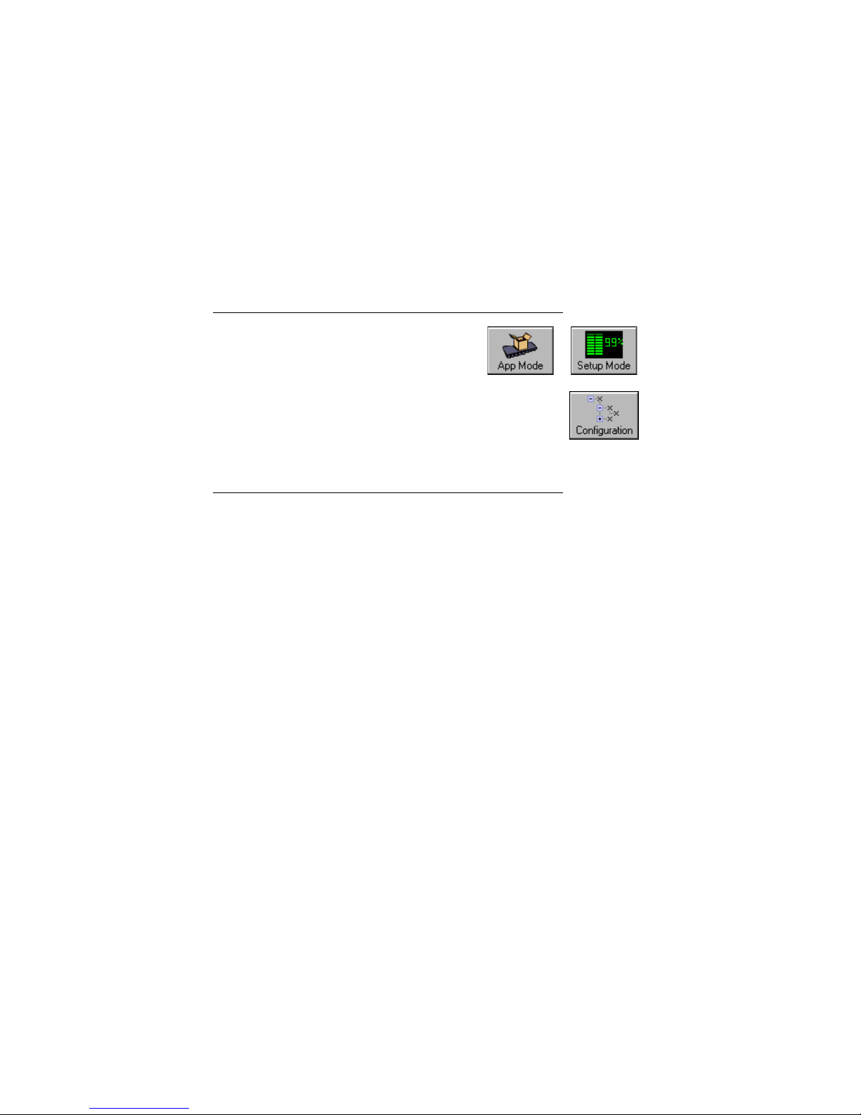
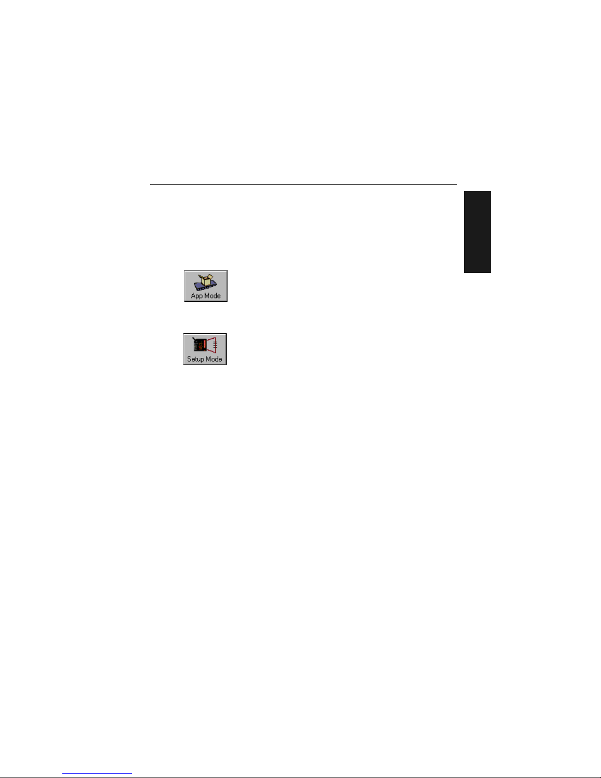
About ESP
ESP is composed of two basic modes Setup
Mode and App Mode (applications). The icons
shown here are used to move between these
modes and are located in the upper left corner of
the ESP window.
In the Ap
p Mode, click the Configuration icon
to bring up the configuration views for Read Cy
cle, Symbolo-
gies, I/O, Matchcode and Diag
nostics.
Note: Throughout ESP, the term “reader” applies to both readers
and scanners.
For more information, see “Using ESP” in chapter 2.
Approvals
This equipment is in compliance or approved by the following organizations:
• UL (Underwriters Laboratories, Inc.)
• cUL (UL mark of Canada)
• FCC (Federal Communication Commission)
•CE Compliant
• BSMI (Bureau of Standards, Metrology and Inspection)
Artisan Technology Group - Quality Instrumentation ... Guaranteed | (888) 88-SOURCE | www.artisantg.com
Page 12
MS-820 Industrial Bar Code Scanner User’s Manual xi
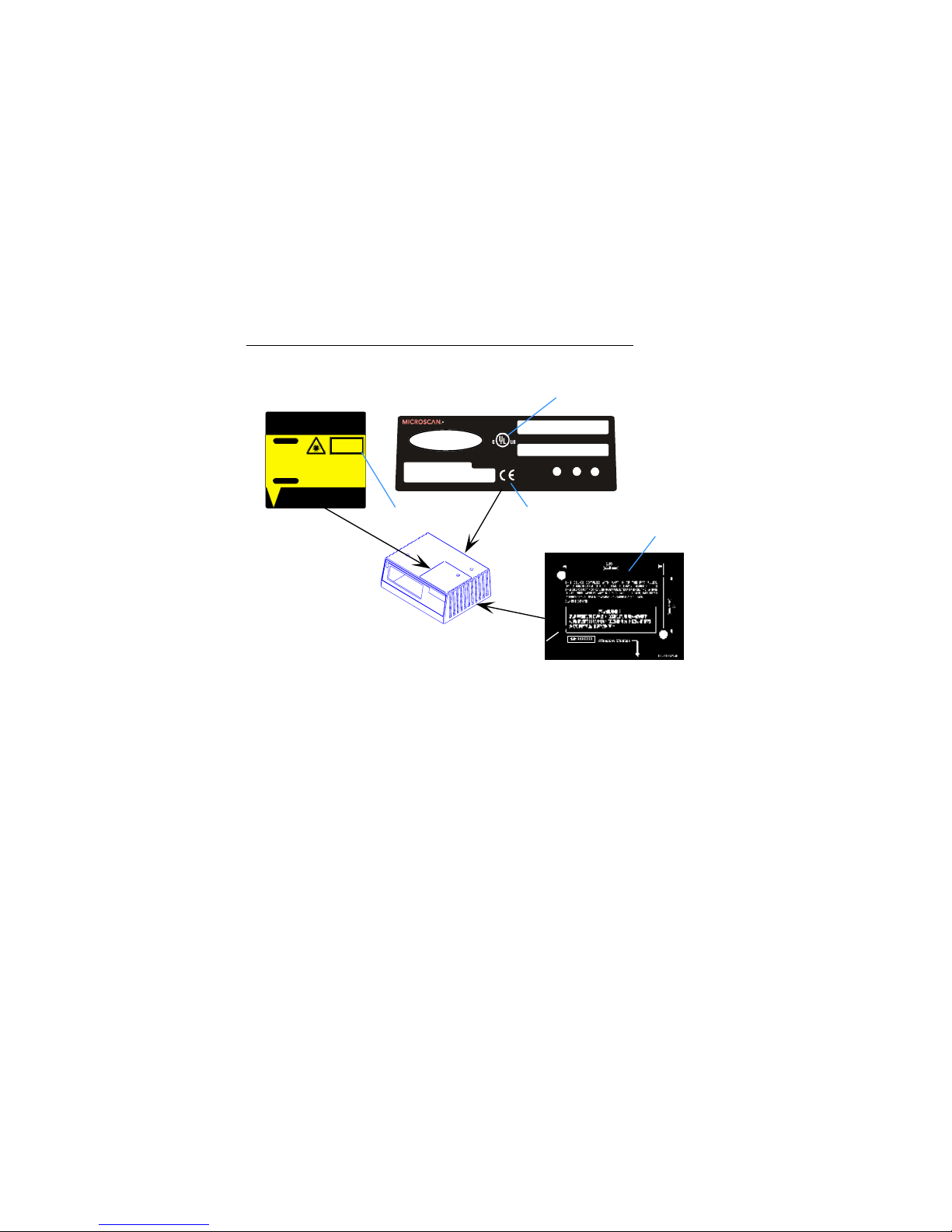
Safety Labels
The following labels are located on the side and back of the MS-820 scanner:
FIS NO.
MANUFACTURED
MADE IN USA
1201 S W 7th St. Renton,W A 98055
RDY PWR
www.microscan.com
LISTED
UL 1 950
4k68
J2
SERIALNUM BER/MODEL NU MBER
GD/RD
11-000031-01
CAUTION-LASERL I GHTWHENOPEN-DO NOTSTARE INTOBEAM.
PRODUCTCONFORMS TOUSADHHS 21CFR SUBCHAPTER"J"
AVOIDEX PO S U R E
LASER LIGHTIS EMITTED F ROM THIS APERTURE
11-000024-01
CAUTION
LASER LIGHTDO NOTSTARE
INTOBEAM.
VORSICHT
LASERSTRAHLUNG, WENNABDECKUNG
GEÖFFNET.NI CHTINDEN STRAHLBLICKEN
650nm LASERDIOD E
1.0 MILLIWATTMA X
CLASS IILA SERPRODUCT
LASERSTRAHLUNGNICHTIN
DENSTRAHLBLICKEN
LASERKLASS E2
94nJ@ 38uS
EN60825-1:1994
DINV DE0837 Teil1: 1994-07
on
Top
on
Back
on
Bottom
BSMI
11-000031-01 S/N Label
11-000024-01
Safety Label
UL, cUL
CE
FCC
CDRH
Artisan Technology Group - Quality Instrumentation ... Guaranteed | (888) 88-SOURCE | www.artisantg.com
Page 13
xii MS-820 Industrial Bar Code Scanner User’s Manual
Warning and Caution Summary
This equipment has been tested and found to comply with the limits for a Class A digital
device, pursuant to part 15 of the FCC Rules. These limits are designed to provide reasonable protection against harmful interference in
a
residential installation. This equip-
ment generates, uses, and can radiate radio frequency energy, and, if
not installed and
used in accordance with the instructions, may cause harmful interference to radio communications. However, there is no guarantee that interference
wi
ll not occur in a particular installation. If this equipment does cause harmful interference to radio or television
reception, wh
ich can be determined by turning the equipment off and on, the user is
encouraged to try to correct the interference by one or more of the following measures:
• Reorient or relocate the receiving antenna
• Increase the separation between th e eq u ipme nt an d rec ei ver
• Connect the equipment into an outlet on a circuit different from
th
at to which the
receiver is connected
• Consult the dealer or an experience
d radio/TV technician for help
For connection to a UL listed direct plug-in power unit marked Class II and rated 10 to
28 VDC at 2.7 watts or greater.
European models must use a similarly rated Class I or Class II power supply that is
certified to comply with standard for safety EN 60950.
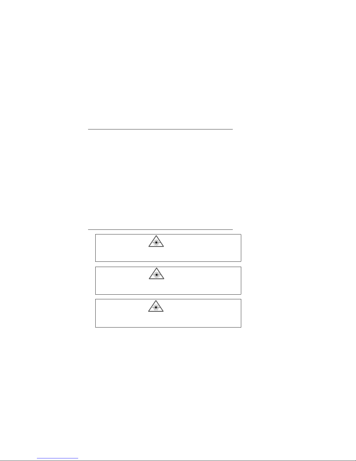
WARNING
Use of controls, adjustments, or performance of procedures other than
those specified herein may result in hazardous laser light radiation
exposure.
WARNING
The laser beam can be harmful to eyesight. Avoid eye contact with the
laser beam. Never point the beam at other people, or in a direction
where people may be passing.
WARNING
There are no user serviceable parts in the scanner. Opening the scanner voids the Microscan Systems warranty and could expose the user
to laser diode power of up to 7 mW.
Artisan Technology Group - Quality Instrumentation ... Guaranteed | (888) 88-SOURCE | www.artisantg.com
Page 14

MS-820 Industrial Bar Code Scanner User’s Manual 1-1
1–Quick Start
Quick Start
Chapter Contents
This chapter is designed to get your scanner up and running quickly using Microscan’s
ESP so the user can get a sense of its capabilities and test bar code symbol samples.
Detailed setup information for installing the scanner into the actual application can be
obtained in the subsequent chapters. ESP is Microscan's proprietary Easy Setup Program, a Windows-based graphic user interface that resides on the user's host computer and allows the user to fully configure
,
test, and operate Microscan's 1D and 2D
symbology readers
As an alternative to ESP,
you can setup the scanner by sending serial commands or by
using the scanner’s embedded menus.
Chapter
1
Step 1 Hardware Required ......................................................................1-2
Step 2 Connect the System.....................................................................1-3
Step 3 Install ESP....................................................................................1-4
Step 4 Select Scanner Model .................................................................. 1-5
Step 5 Autoconnect .................................................................................1-6
Step 6 Position Symbol and Scanner......................................................1-7
Step 7 Test for Read Rate.......................................................................1-8
Step 8 Configure the Scanner .................................................................1-9
Artisan Technology Group - Quality Instrumentation ... Guaranteed | (888) 88-SOURCE | www.artisantg.com
Page 15
1-2 MS-820 Industrial Bar Code Scanner User’s Manual
1–Quick Start
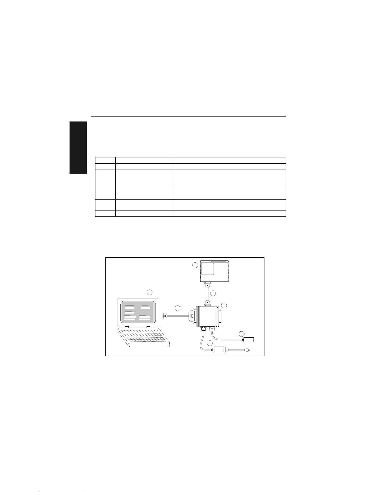
Step 1 — Hardware Required
(Refer to figure 1-1.)
Caution: If using yo
ur own power supply, be certain that it is wired correctly and supplies voltage is within the +10 to 28 VDC limits. Incorrect wiring or voltage can cause
software or
equipment failures.
Item Part Number Description
1 FIS-0820-XXXXG MS-820 s c a nn e r
2 A host computer
a
a. With either a terminal communications program or Microscan’s ESP which runs under Windows
operating system, Windows-98 or higher, including Windows NT and Windows XP.
3 61-300026-03
DB-25 Null modem configuration cable plug to DB-9
socket,
6 ft.
b
or a 25-pin cable to the 25-pin port
b. If using another host cable, make certain it does not have RTS/CTS connected to the host.
4 98-000014-02 IB-131 interface kit including (5) interface cable
5 61-000011-02 Null modem configuration cable
6
97-100004-15
(90-264 VAC, 24VDC)
Power supply
7 99-000017-01 Optional object detector
6
1
5
7
4
Scanner
Host
N
e
t
w
o
r
k
TriggerPower
3
2
Figure 1-1 Hardware Configuration
Artisan Technology Group - Quality Instrumentation ... Guaranteed | (888) 88-SOURCE | www.artisantg.com
Page 16
Chapter 1 Quick Start
MS-820 Industrial Bar Code Scanner User’s Manual 1-3
1–Quick Start
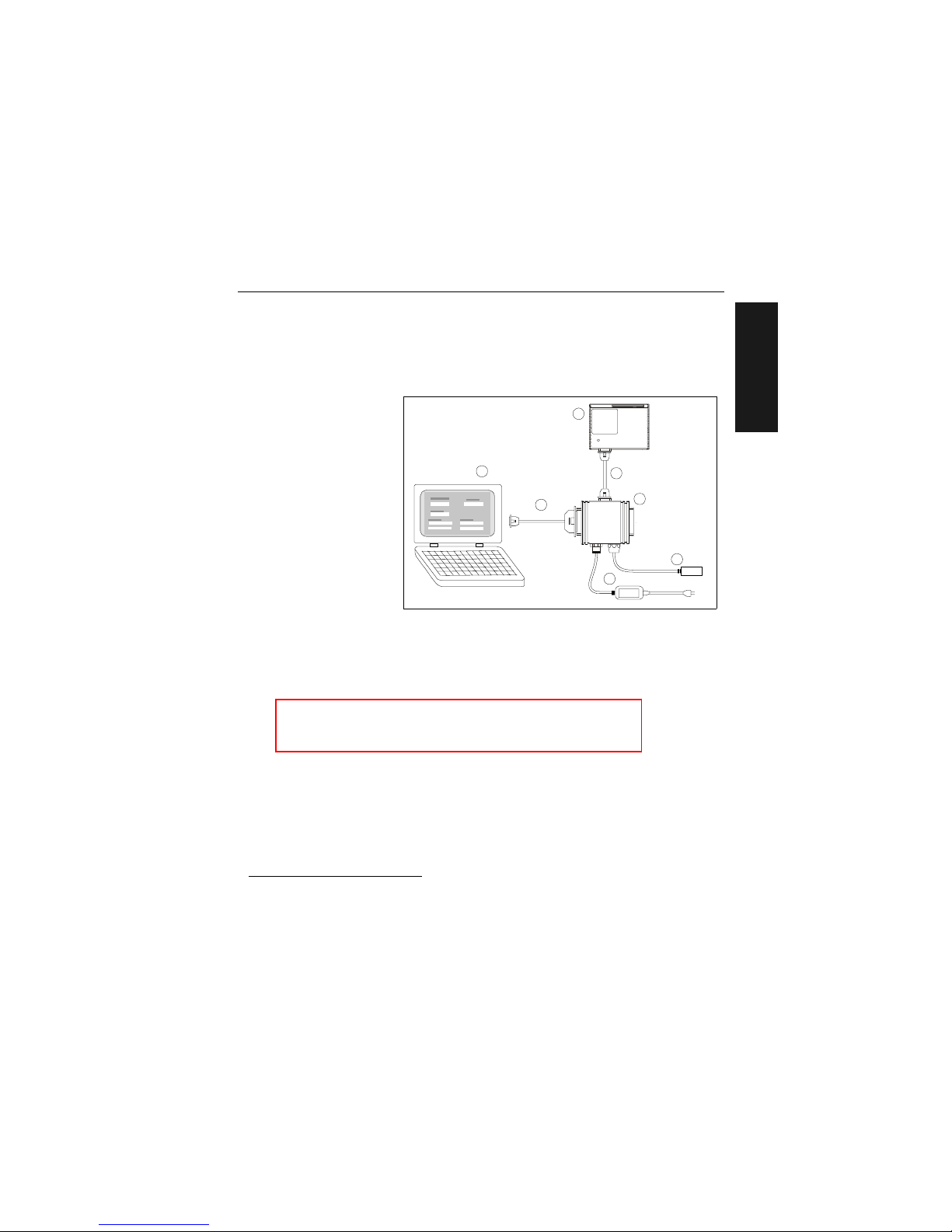
Step 2 — Connect the System
(Refer to figure 1-2.)
1. Connect the scanner
(1) to the IB-131
interface box (4)
using the supplied
cable (5).
1. If making up your
own ca
ble, make
certain that you connect transmit pins to
re
ceive pins.
2. Connect the IB-131
(4) at the “HOST”
25-pin connector to
the computer (2) via
a null modem cable
(3).
1
3. Connect the power
supply (6) to the
IB-131’s POWER
connector.
4. Connect power to the system.
1. When wiring the IB-131 to a host computer which has a 25-pin connector, cross pins 2 and 3.
When wiring the IB-131 to a host computer which has a 9-pin connector, do NOT cross pins 2
and 3.
Figure 1-2 Hardware Configuration
6
1
5
7
4
Scanner
Host
N
e
t
w
o
r
k
TriggerPower
3
2
Caution:
1. Be sure all cables are connected BEFORE applying power.
2. Always power down BEFORE disconnecting any cables.
Artisan Technology Group - Quality Instrumentation ... Guaranteed | (888) 88-SOURCE | www.artisantg.com
Page 17

1-4 MS-820 Industrial Bar Code Scanner User’s Manual
1–Quick Start
Step 3 — Install ESP
1
(ESP is short for Easy Setup Program.)
With your scanner connected to a host computer with Windows operating system, you
can use the ESP to configure and control the scanner.
1. Insert your Microscan CD into your computer’s CD drive.
2. Launch Setup.exe under ESP and follow the prompts.
If downloading from the web:
a) Go to http
://www.microscan.com/downloadcenter/
b) Enter company information.
c) Select ESP and download to your co
mputer hard drive.
d) Extract ESP Wi
nZip files to a directory of your choice.
3. Note where your ESP.exe file is stored on your hard drive.
At the end of the install process, copy a shortcut of the ESP icon to the desktop.
4. Click the ESP icon
to start the program.
1. You can also access the scanner through its embedded menus. See “Embedded Menus” on
page A-20.
Artisan Technology Group - Quality Instrumentation ... Guaranteed | (888) 88-SOURCE | www.artisantg.com
Page 18
Chapter 1 Quick Start
MS-820 Industrial Bar Code Scanner User’s Manual 1-5
1–Quick Start
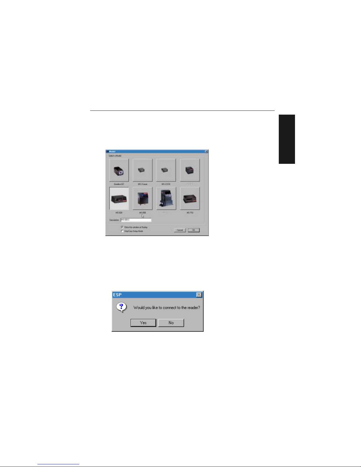
Step 4 — Select Scanner Model
When you start the program, the following menu will appear:
Note: If you need to select another model late
r, you can find it in the App Mode under
Model on the menu bar.
1. In the Model dialog bo
x, select your model.
If you do not want to make this selection every time you load ESP, uncheck Show
this window at
Startup.
2. Select the default name, for example MS-820-1, or type in a file name of y
o
ur
choice and click OK.
3. Click Yes when the connect to the scanner dialog appears.
Artisan Technology Group - Quality Instrumentation ... Guaranteed | (888) 88-SOURCE | www.artisantg.com
Page 19
1-6 MS-820 Industrial Bar Code Scanner User’s Manual
1–Quick Start
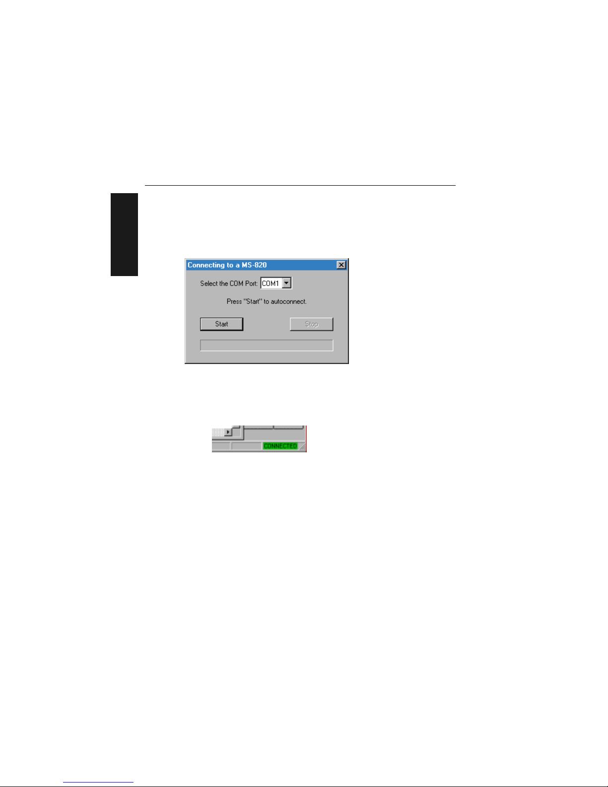
Step 5 — Autoconnect
1. In the Connecting to... dialog, select you r commun ic atio ns port u nde r COM
Port.
2. Click the St
art button.
3
. Allow time for the autoconnect routine to test all of the combin ations . You will see
a blue progress bar fill across the Connecting to... dialog.
When connected, the CONNECTED message will appear in a green bo x in t he st a-
tus bar on the bottom right of the dialog.
Tip: If connection fails, enable a different Com port and try again.
Tip: If you do not see either the CONNECTED or DISCONNECTED message at the bot-
tom
of your dialog, try expanding the ESP window horizontally.
Artisan Technology Group - Quality Instrumentation ... Guaranteed | (888) 88-SOURCE | www.artisantg.com
Page 20
Chapter 1 Quick Start
MS-820 Industrial Bar Code Scanner User’s Manual 1-7
1–Quick Start
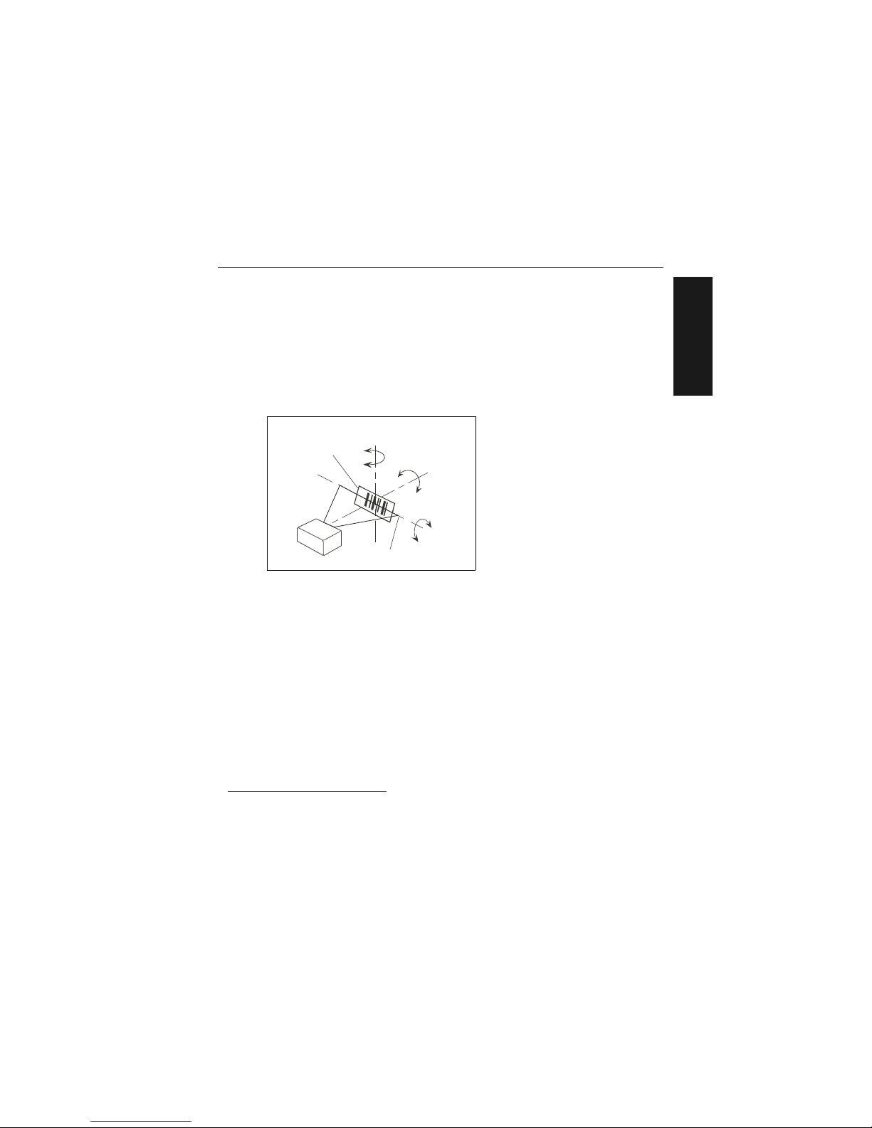
Step 6 — Position Symbol and Scanner
1. Set up a bar code symbol1 at the scanning distance you will be using in your
application.
2
2. Avoid bright light or IR light from other sources, including other scanners.
3. Pitch symbol or scanner a minimum of ±15° to avoid specular reflection, t he
retu
rn of direct, non-diffused light.
4.
Code 39 is the
default symbol type enabled. If you are uncertain as to your symbology
type, enable all codes (see “Autodiscriminate” on
page 5-26).
1. If using an I 2/5 symbol, verify that the number of characters in the symbol being scanned
matches the symbol length enabled for the I 2/5 symbol type (default is 10 and 6). See “Inter-
leaved 2 of 5” on page 5-11.
2. Consult “LED Indicators” on page A-3.
Pitc
h
axis
Bar code
label
Til
t
ax
is
Skew
axis
Scan line
S
canner
Figure 1-3 Symbol/Scanner Position
Artisan Technology Group - Quality Instrumentation ... Guaranteed | (888) 88-SOURCE | www.artisantg.com
Page 21
1-8 MS-820 Industrial Bar Code Scanner User’s Manual
1–Quick Start
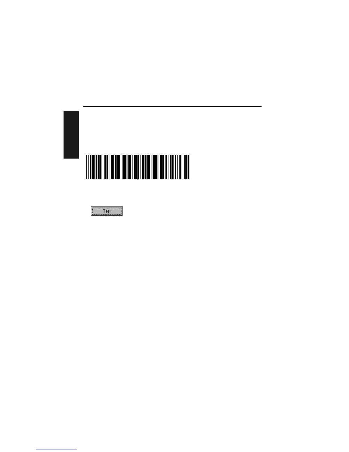
Step 7 — Test for Read Rate
If you don’t have a test symbol, print out this page and use the symbol here for
testing.
By ESP
After connecting to the scanner, ESP will open in Easy Setup Mode.
1. Click the Test button in Easy Setup Mode to begin the read rate test.
2. Follow the instructions in Easy Setup Mode screen.
3. To end the Read Rate test, click the Stop button.
Note: If the scanner is
in the default Continuous Read mode, it will read and beep
repeatedly as long as a readable symbol remains in the read range and the read cycle
configuration has not changed.
Note: S
ee “Formulas for Nu
mber of Decodes” on page A-27 for additional infor-
mation on scan width and depth of field.
By Serial Commands
Send an <C> to begin the read rate test.
Send a <J> to end the read rate test.
20 mil Code 39 Test Symbol
You can also find test symbols on the
back of the Microscan Marketing CD
jacket. The 20 mil refers to the width of
the narrowest bar (e.g., 7.5 mil =
.0075" or .1905 mm).
Artisan Technology Group - Quality Instrumentation ... Guaranteed | (888) 88-SOURCE | www.artisantg.com
Page 22
Chapter 1 Quick Start
MS-820 Industrial Bar Code Scanner User’s Manual 1-9
1–Quick Start
Step 8 — Configure the Scanner
By ESP
To make change scanner settings, or to access the utilities or terminal window, click on
the App Mode button.
To return to the Easy
Setup Mode, click on the Setup Mode button.
See Chapter 2, “Using ESP” for detailed explanation of ESP features.
By Serial Commands
From your terminal program or the terminal screen in ESP, you can enter serial string
commands configuration and utility commands as described herein.
See “Serial Configuration Comm
ands” on page A-13 and “Summary of Utility
Serial Commands” on page 11-3.
Note: You can learn the current setting of any parameter by inserting a question mark
after
the number, as in <KA?> To see all “K” commands, send <K?>.
By Embedded Menu
From your terminal program you can send a <D> command to access the embedded
menus.
See “Embedded Menus” on page A-20.
Artisan Technology Group - Quality Instrumentation ... Guaranteed | (888) 88-SOURCE | www.artisantg.com
Page 23

1-10 MS-820 Industrial Bar Code Scanner User’s Manual
1–Quick Start
Artisan Technology Group - Quality Instrumentation ... Guaranteed | (888) 88-SOURCE | www.artisantg.com
Page 24

MS-820 Industrial Bar Code Scanner User’s Manual 2-1
2–Using ESP
Using ESP
Chapter Contents
This section is designed to help you understand the structure, elements, and application
of the ESP (Easy Setup Program).
When you start up ESP , unless otherwise sp
ecified, you will enter the Easy Setup mode
for initial setup. From there, you move easily into the App Mode (application mode)
where you can access several configuration and utilities menus.
Chapter
2
Easy Setup Mode ....................................................................................2-2
Application Mode .....................................................................................2-3
Pulldown Menus ......................................................................................2-4
Making Changes in ESP......... ... ..............................................................2-6
Send/Receive Options.............................................................................2-7
Artisan Technology Group - Quality Instrumentation ... Guaranteed | (888) 88-SOURCE | www.artisantg.com
Page 25

Easy Setup Mode
2-2 MS-820 Industrial Bar Code Scanner User’s Manual
2–Using ESP
Easy Setup Mode
In Easy Setup Mode you are presented with the Test option and if appropriate for
your application, Calibration. After connecting to your scanner (or reader) the Setup
Mode will first appear. This will provide you with instructions specific to your model that
will help you in positioning, testing, and if appropriate, calibrating.
Test
Click the Test button to start the read rate test for a quick indication of the read capabilities and the limits of your application. When Deco
des per Second is unchecked,
the test will count the percentage of decodes relative to the number of actual scans.
Click Stop to end the test.
Calibrate
Some models include a calibration routine that will optimize reads by comparing read
rates at various settings in focal lengths, scan speeds, and gain settings.
Note: This view may be
slightly different for each
model.
Test button
Calibration is available on some models
Click here to change
from percentage of
good decodes to
decodes per second
Saves Calibration
results (if available)
Ends the read rate
test
On some models, clicking Auto Discriminate
will enable most available symbology types.
Artisan Technology Group - Quality Instrumentation ... Guaranteed | (888) 88-SOURCE | www.artisantg.com
Page 26
Chapter 2 Using ESP
MS-820 Industrial Bar Code Scanner User’s Manual 2-3
2–Using ESP
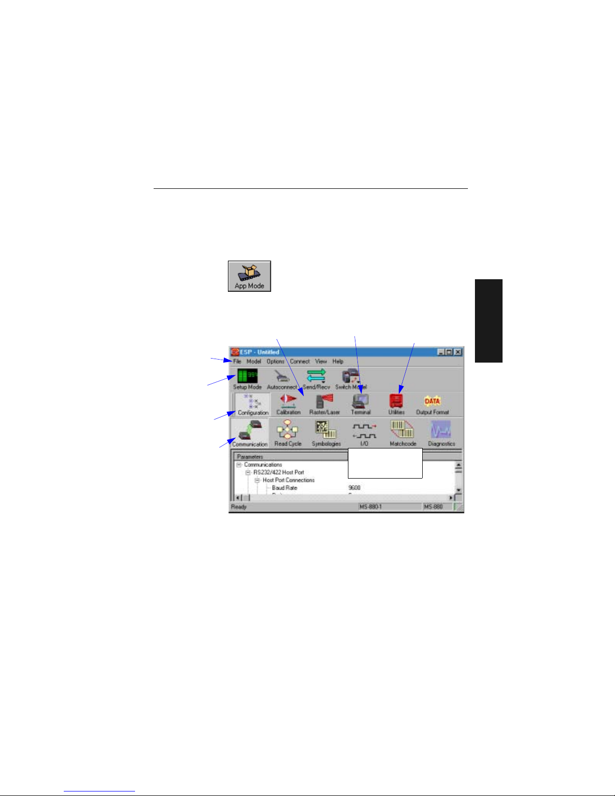
Application Mode
From Easy Setup Mode, you can click on the App Mode button to access specific configuration menus, utilities, and a terminal window where serial commands can be
entered.
Note th
at the App Mode and Setup Mode buttons appear in the same position to allow
easy switching between these primary modes.
Note: F
or specific information on any of the icons
shown above in the operations bar or
configuration bar, see specific chapters in this document.
Click this icon to
return to Easy
Setup mode
Click this icon to
return to this view
from Utilities or
Terminal
Click here to open
a terminal window
Click on icons in this
toolbar to access
configuration menu
trees to make specific changes in configuration
Note: This view may be
slightly different for
each model.
The icons on this
toolbar are for operations
Pulldown menus
Click here to
access read rate
and other utilities
Artisan Technology Group - Quality Instrumentation ... Guaranteed | (888) 88-SOURCE | www.artisantg.com
Page 27
Pulldown Menus
2-4 MS-820 Industrial Bar Code Scanner User’s Manual
2–Using ESP
Pulldown Menus
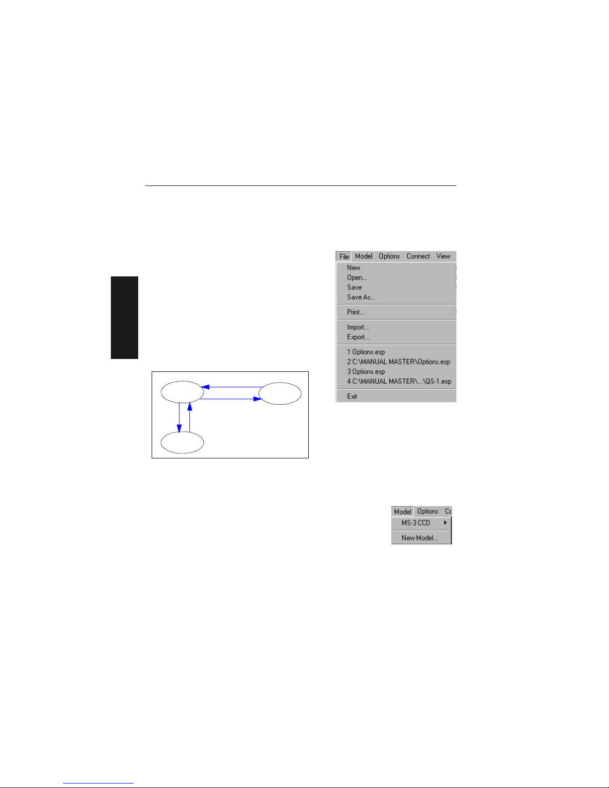
File
New
Whenever New is selected, the default configuration of ESP is loaded.
Open/Save
When Save or Save As is selected, the ESP configuration is saved to the host computer’s hard
drive and
available whenever the same file is
selected under Open.
Important:
Whe
n you save menu changes to
your hard drive, these changes are not saved to
your scanner. Figure 2-1 shows how settings can
be saved and received between ESP and the scanner and ESP and the host hard drive.
Import/Export
Export converts the active ESP configuration settings to an ASCII text file. Import converts
the ASCII settings from a text file to ESP configuration settings.
Model
When you select New Model, you can define configuration settings
for another model. When you save to the hard drive, you will be
saving the settings of all the models defined in a single ESP file.
ESP
Host hard
drive
Scanner
Save to Reader
Receive Reader Settings
File
Save
File
Open
Figure 2-1 How Settings
are Saved
Artisan Technology Group - Quality Instrumentation ... Guaranteed | (888) 88-SOURCE | www.artisantg.com
Page 28
Chapter 2 Using ESP
MS-820 Industrial Bar Code Scanner User's Manual 2-5
2–Using ESP
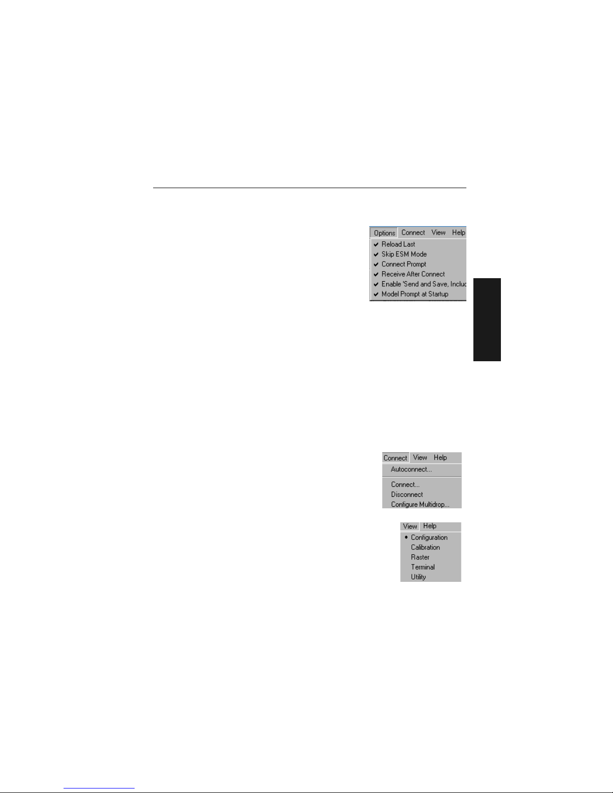
Options
You can use the Options menu to tell ESP how you wish
it to perform at startup.
Note: The settings you select here will be saved and be
loaded into ESP when ESP is opened next, whether or not
you save the ESP file to the computer.
Reload Last
At startup, reloads the last file saved to the computer.
Skip ESM Mode
Skips the Easy Setup Mode and opens directly in the App Mode.
Connect Prompt (enabled by default)
At startup, asks if you would like to connect to the scanner.
Receive After Connect
At startup, loads the scanner’s settings into ESP. (This is not recommended if you w ant
to preserve your ESP settings for future use.)
Enable ‘Send and Save, Including Factory’
Enables the ‘Send and Save, Including Factory’ option in the Send/Recv command.
Model Prompt at Startup (enabled by default)
At startup, prompts you to select a scanner model. If this is unchecked, then ESP will
automatically load the last model accessed.
Connect
Generally Autoconnect will be the quickest way that ESP
can get connected to a scanner. Autoconnect will try connecting at the most common communications settings and
step
through the v
arious settings until they match up with
the host’s settings.
When you select Connect, you will need to manually select
the communications settings from a popup dialog.
View
View tells you what view is current and allows you to quickly move
to other views which are also accessed by clicking the icons on the
toolbars.
Artisan Technology Group - Quality Instrumentation ... Guaranteed | (888) 88-SOURCE | www.artisantg.com
Page 29
Making Changes in ESP
2-6 MS-820 Industrial Bar Code Scanner User’s Manual
2–Using ESP
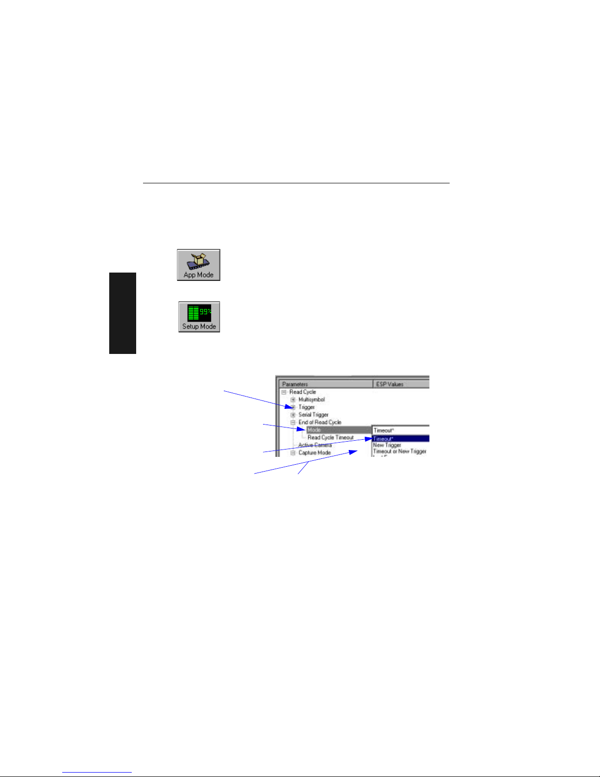
Making Changes in ESP
To change scanner settings, or to access the utilities or terminal window, click on the
App Mode button.
To return to the Easy Se
tup Mode, click on the Setup Mode button.
See the succeeding chapters and Appendices to see spec
ific configuration command
explanations for both ESP and serial commands.
To make changes to a configuration setting in the menu trees:
1. Left click on the + to
expand tree
2. Double click on parame-
ter and click once in selection box to view options.
3. Place your curser in the
selection box, scroll down
to the setting you want to
change and click once on
the setting.
4. Left click again on the
open screen to complete
the selection.
5. Right click on the open screen and select
Save to Scanner to implement the com-
mand in the scanner.
Artisan Technology Group - Quality Instrumentation ... Guaranteed | (888) 88-SOURCE | www.artisantg.com
Page 30
Chapter 2 Using ESP
MS-820 Industrial Bar Code Scanner User’s Manual 2-7
2–Using ESP
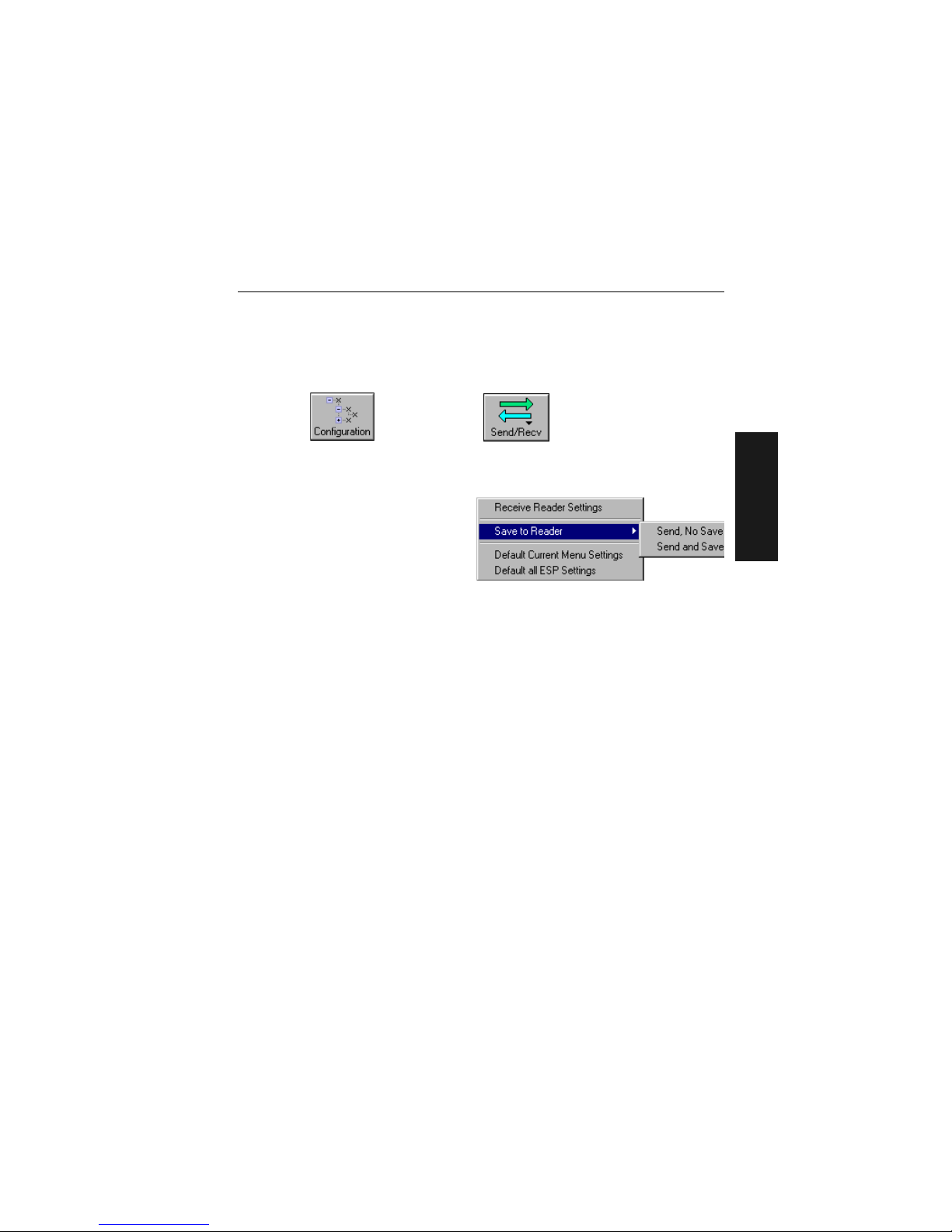
Send/Receive Options
To access save and receive options, from the Configuration views click the
Send/Recv button:
Y
ou can also access this selector by right-clicking in any of the configuration views.
Saving
You have 3 choices for saving:
1. Send, No Save.
This saves ESP settings to current
memory.
2. Send and Save.
This activ
ates all changes in current
memory
and saves to the scanner for power-on. (Similar to the <Z> command.)
3. Send and Save, Including Factory. Includes all settings including changes to
factory settings.
For Multidrop setup,
see “Multidrop Communications” on page A-32.
For Matchcode setup, see Chapter 7, “Matchcode.”
For more on defaulting and saving settings, see “Defaulting/Saving/Initializing” on
page A-21.
Receiving
From the Send/Recv selector select Receive Reader Settings.
This is useful if you want to receive (upload) the scanner’s settings and sa ve them as a
computer file for la
ter retrieval and to verify that your ESP settings have been saved or
that you have not saved any unwanted changes that you or someone else previously
made in ESP.
Defaulting
When you select Default Current... or Default all ESP... you are only defaulting the
ESP settings. To default the scanner, see “Defaulting/Saving/Resetting” on page
A-21 for a more information.
Artisan Technology Group - Quality Instrumentation ... Guaranteed | (888) 88-SOURCE | www.artisantg.com
Page 31

Send/Receive Options
2-8 MS-820 Industrial Bar Code Scanner User’s Manual
2–Using ESP
Artisan Technology Group - Quality Instrumentation ... Guaranteed | (888) 88-SOURCE | www.artisantg.com
Page 32

MS-820 Industrial Bar Code Scanner User’s Manual 3-1
3–Communications
Communications
Chapter Contents
With Microscan’s ESP™ (Easy Setup Program), configuration changes can be made in
the ESP menus, then sent and saved to your scanner. The user can also send serial
commands to the scanner via the ESP’s Terminal window.
This section includes connecting parameters and options for communicating by the auxiliary port and various interfaces.
Note: The
characters NULL <> and , can only be entered through embedded menus,
not through ESP or serial commands.
Note: Default settings f
or establishing communications are:
Baud = 9600
Parit y = Even
Stop Bits = One
Data Bits = Seven
Flow Control = No
ne
Chapter
3
Communications by ESP.........................................................................3-2
RS-232/422 Host Port..............................................................................3-3
RS-232 Auxiliary Port .......... ... ... ..............................................................3-9
Preamble ...............................................................................................3-17
Postamble..............................................................................................3-18
LRC Status ............................................................................................3-19
Response Timeout.................................................................................3-20
Intercharacter Delay ..............................................................................3-21
Artisan Technology Group - Quality Instrumentation ... Guaranteed | (888) 88-SOURCE | www.artisantg.com
Page 33

Communications by ESP
3-2 MS-820 Industrial Bar Code Scanner User’s Manual
3–Communications
Communications by ESP
Communications by Serial Command
Command Title Format
Host Port Connections <Kabaud,parity,stop bits,data
bits>
Host Protocol <Kfprotocol>
RS4
22 Status <Kbstatus>
Auxiliary Port
<Kyaux port mode,baud,parity,stop bits,data bits,daisy
ch
ain status,daisy chain ID>
Preamble <Kdstatus,preamble>
Po
stamble <Kestatus,postamble>
LRC <Kcstatus>
R
esponse Timeout <KAresponse timeout>
Interchar
acter Delay <KBintercharacter delay>
Click this button to bring up
the Communications menu.
To change a setting,
double-click the
setting and use your
cursor to scroll
through the options.
To open nested options,
single-click the +.
To change a setting,
double-click the
setting and use your
cursor to scroll
through the options.
Artisan Technology Group - Quality Instrumentation ... Guaranteed | (888) 88-SOURCE | www.artisantg.com
Page 34

Chapter 3 Communications
MS-820 Industrial Bar Code Scanner User’s Manual 3-3
3–Communications
RS-232/422 Host Port
Includes host port connections and host protocols.
Host Port Connections
Baud Rate, Host Port
Parity, Hos t Por t
Stop Bits, Host Port
Usage: Can be used to transfer data faster or to match host port settings.
Definition: The rate at which the scanner and host transfer data back and forth.
Serial Cmd: <Kabaud rate,parity,stop bits,data bits>
Default: 9600
Options: 0 = 600
1 = 1200
2 = 2400
3 = 4800
4 = 9600
5 = 19.2 K
6 = 38.4 K
7 = 57.6 K
8 = 300
Usage: Only changed if necessary to match host setting.
Definition: An error detection routine in which one d ata bit i n each ch ar acter is set t o
1 or 0 so that the total number of 1 bits in the data field is even o r odd.
Serial Cmd: <Kabaud rate,parity,stop bits,data bits>
Default: Even
Options: 0 = None 1 = Even 2 = Odd
Usage: Only changed if necessary to match host setting.
Definition: One or two bits added to the end of each character to indicate the end of
the character.
Serial Cmd: <Kabaud rate,parity,stop bits,data bits>
Default: One
Options: 0 = One 1 = Two
Artisan Technology Group - Quality Instrumentation ... Guaranteed | (888) 88-SOURCE | www.artisantg.com
Page 35

RS-232/422 Host Port
3-4 MS-820 Industrial Bar Code Scanner User’s Manual
3–Communications
Data Bits, Host Port
Host Protocol
Point-to-Point (standard)
Usage: Only changed if necessary to match host setting.
Definition: Number of bits in each character.
Serial Cmd: <Kabaud rate,parity,stop bits,data bits>
Default: Seven
Options: 0 = Seven 1 = Eight
Usage: In general, the point-to-point protocols will work well in most applica-
tions. They require no address and must use RS-232 or RS-422 communications standards.
Definition: Protocols define the sequence and format in which information is trans-
ferred between the scanner and the host, or in the case of Multidrop,
between scanners and a concentrator.
Serial Cmd: <Kfprotocol>
Default: Point-to-Point
Options: 0 = Point-to-Point
1 = Point-to-Point with RTS/CTS
2 = Point-to-Point with XON/XOFF
3 = Point-to-Point with RTS/CTS &
XON/XOFF
4 = Polling Mode D
5 = Multidrop
6 = User Defined
7 = User Defined Multidrop
If selecting one of the options from 0 to 4 (Point-to-Point, Point-to-
Point with RTS/CTS, Point-to-Point with XON/XOFF, Point-to-
Point with RTS/CTS and XON/XOFF, or Polling Mode D), use the
<K140,protocol> format.
Option 5 through 7 are special cases and discussed later in this section.
Usage: Used only with RS-232 or RS-422.
Definition: Standard Point-to-Point requires no address and sends data to the host
whenever it is available, without any reque st or handshake from the host.
Serial Cmd: <Kf
0>
Artisan Technology Group - Quality Instrumentation ... Guaranteed | (888) 88-SOURCE | www.artisantg.com
Page 36

Chapter 3 Communications
MS-820 Industrial Bar Code Scanner User’s Manual 3-5
3–Communications
Point-to-Point with RTS/CTS
Point-to-Point with XON/XOFF (Transmitter On/Off)
Point-to-Point with RTS/CTS & XON/XOFF
Polli ng M ode D
Usage: A scanner initiates a data transfer with an RTS (request-to-send) trans-
mission. The host, when ready, responds with a CTS (clear-to-send) and
the data is transmitted. CTS and RTS signals are transmitted over two
dedicated wires as defined in the RS-232 standard.
Used only with RS-232.
Definition: Point-to-Point with RTS/CTS (request-to-send/clear-to-send) is a
simple hardware handshaking protocol that allows a scanner to initiate
data transfers to the host.
Serial Cmd: <Kf1>
Usage: If an XOFF has been received from the host, data will not be sent to the
host until the host sends an XON. During the XOFF phase, the host is free
to carry on other chores and accept data from other devices.
Used only with RS-232.
Definition: This option enables the host to send the XON and XOFF command as a
single byte transmission command of start (^Q) or stop (^S).
Serial Cmd: <Kf2>
Usage: Used only with RS-232.
Definition: This option is a combination of Point-to-Point with RTS/CTS and
Point-to-Point with XON/XOFF.
Serial Cmd: <Kf3>
Usage: When in Polling Mode D, an address of 1 is automatically displayed on
the configuration screen. However, during transmission, a 1C hex poll
address (FS) and a 1D hex select address (GS) are substituted for the 1.
Definition: Like Point-to-Point, Polling Mode D requires a dedicated connection to
the host; but unlike Point-to-Point, it requires an address and must
wait for a poll from the host before sending data.
Serial Cmd: <Kf4>
Artisan Technology Group - Quality Instrumentation ... Guaranteed | (888) 88-SOURCE | www.artisantg.com
Page 37

RS-232/422 Host Port
3-6 MS-820 Industrial Bar Code Scanner User’s Manual
3–Communications
Multidrop
Note: See also “Multidrop Communications” on page A-32.
Note: Scanne
rs linking up to a Microscan MS-5000 multidrop concentrator must be
configured in standard multidrop protocol.
User Defined Point-to-Point
User Defined Address
Usage: The MS-5000 can be used as a concentrator to a single host port connec-
tion.
Definition: Multidrop allows up to 50 devices to be connected to a single RS-485
host, with the scanner assigned an unique address (from 01 to 50). When
Multidrop is selected, the protocol characters for RES, REQ, etc. are
assigned automatically.
Multidrop
Addresses:
Each address has its own separate poll and select address (from 1C to 7F
hex).
Options: 01 through 50
Serial Cmd: If selecting Multi
d
rop <K140,5> fan address must be defined and
appended to the command string.
Format: <Kf5,add
ress[01 to 50]>Format: <K140, 5,address[01 to 50]>
Usage: Used for dev
eloping custom protocols in polled or unpolled mode.
Definition: User Defined Point-to-Point allows the user to customize the point-to-
point protocol.
Serial Cmd: <Kf6,RES,address,REQ,EOT,STX,ETX,ACK,NAK,from host>
Definition: User Defined is considered to be in a polled mode only if an address has
been assigned.
Serial Cmd: <Kf6,RES,address,REQ,EOT,STX,ETX,ACK,NAK,from host>
Default: No address
Options: Any ASCII character except a null.
Artisan Technology Group - Quality Instrumentation ... Guaranteed | (888) 88-SOURCE | www.artisantg.com
Page 38

Chapter 3 Communications
MS-820 Industrial Bar Code Scanner User’s Manual 3-7
3–Communications
User Defined Example
From Host
Example: An ACK/NAK protocol can be configured using User Defined. The scan-
ner will transmit data to the host when an ACK is received. If a NAK or
response timeout occurs, the scanner will re-send the data to the host up
to 3 more times before aborting.
Tip: To use User Defined Point-to-Point, first select Point-to-Point
<K140,0> and then User Defined <K140,f6>.
Example: To select an unpolled ACK/NAK User Defined protocol with
LRC disabled, send <Kf0><Kf6,,,,,,,^F,^U><Kc0>. ACK and NAK will
be displayed in the menu.Tip: To use User Defined Point-to-Point,
first select Point-to-Point <Kf
0> and then User Defined <Kf6>.
Example: To select an unpolled ACK/NAK User Defined protocol with
LRC disabled, send <Kf0><Kf6,,,,,,,^F,^U><Kc0>. ACK and NAK will
be displayed in the menu.
Serial Cmd: <Kf6,RES,address,REQ,EOT,STX,ETX,ACK,NAK,from host>
Default: No assignment
Options: Any ASCII character except a null. Control characters can be used to
define RES through NAK in serial commands.
Definition: Allows the handshaking protocol to be initiated from the host, if not con-
figured in an unpolled mode. Messages sent to the host will include the
scanner’s defined protocol. The status of From Host determines if mes-
sages sent from the host to the scanner must include the defined protocol. If From Host is disabled, the defined protocol is not included. If
From Host is enabled, the defined protocol must be included.
Serial Cmd: <Kf
6,RES,address,REQ,EOT,STX,ETX,ACK,NAK,from host>
Default: Disabled
Options: 0 = Disabled 1 = Enabled
Artisan Technology Group - Quality Instrumentation ... Guaranteed | (888) 88-SOURCE | www.artisantg.com
Page 39

RS-232/422 Host Port
3-8 MS-820 Industrial Bar Code Scanner User’s Manual
3–Communications
User Defined Multidrop
Note: Any ASCII character except a null (00) and a ^A (01) can be assigned as an
address. Control characters can be used to define RES through NAK in serial commands. See (See “Communication Protocol Comm
and
s” on page A-19.)Note:
Definitions of commands in Use
r Defined and User Defined Multidrop must be dupli-
cated in host applications to enable poll and select sequences to execute correctly during transmission.
Note: T
ypically, parameters in Use
r Defined Multidrop are defined by first enabling
Multidrop, then enabling User Defined Multidrop. This pre-loads multidrop charac-
ters into the parameters. Then changes are made to individual characters to match the
host
or other requirements.
Host RS-422 Status
Usage: Used when connecting to a concentrator or other device that does not
match standard multidrop protocol.
Definition: User Defined Multidrop allows the user to customize the polling protocol.
If selecting User Defined Multidrop (7), complete the format by either
choosing new parameters or place commas where unchanged data fields
occur.
Serial Cmd: <Kf7,RES,address,R
E
Q,EOT,STX,ETX,ACK,NAK>
For User Defined Multidrop, first select Multidrop <KF5>, then User
Defined Multidrop <KF7...>.
Address: Any single character (02 hex to 7E hex) in the ASCII table can be
assigned as the address character. The character chosen is used as the
poll character and the subsequent ASCII character becomes the select
character. For example, if a ^B (02 hex) is selected as the address, ^C
(03 hex) becomes the select address that the host will use in sending
host select commands.
Usage: Only changed
i
f necessary to match host setting.
Definition: Enables RS-422. When RS-422 is enabled, RS-232 is disabled.
Serial Cmd: <Kbstatus>
Default: Disabled
Options: 0 = Disabled 1 = Enabled
Artisan Technology Group - Quality Instrumentation ... Guaranteed | (888) 88-SOURCE | www.artisantg.com
Page 40

Chapter 3 Communications
MS-820 Industrial Bar Code Scanner User’s Manual 3-9
3–Communications
RS-232 Auxiliary Port
Note: The aux port cannot be used when the host port is set to RS-422 or Multidrop.
As with the host port parameters, the auxiliary terminal’s settings (baud rate, parity,
stop bits, and data bits) must be identical with those of the auxiliary device.
Aux Port Connections
As with the host port parameters, the auxiliary terminal’s settings (baud rate, parity,
stop bits, and data bits) must be identical with those of the auxiliary device.
Baud Rate, Aux Port
Parity, Aux Port
Usage: These commands set the communication parameters with the auxiliary
port which can be used to configure menus, send data to the host, display data transmissions originating from the host of the scanner, and
rela
y
data from other scanners set in tandem (daisy chained).
Definition: An auxiliary port connects the scanner to a remote display or to other
scanners that can display or transfer data.
Usage: Can be used to transfer data faster or match an auxiliary device.
Definition: The rate at which the scanner and host transfer data back and forth.
Serial Cmd: <Kyaux port mode,baud rate,parity,stop bits,data bits,daisy chain ID
status,daisy chain ID>
Default: 9600
Options: 0 = 600
1 = 1200
2 = 2400
3 = 4800
4 = 9600
5 = 19.2 K
6 = 38.4 K
7 = 76.8 K
a
8 = 300
a. Not available in ESP.
Usage: Only changed if necessary to match host setting.
Definition: An error detection routine in which one data bit in each ch ar a cter is set to
1 or 0 so that the total number of 1 bits in the data field is even o r odd.
Default: Even
Options: <Kyaux port mode,baud rate,parity,stop bits,data bits,daisy chain ID
status,daisy chain ID>
Serial Cmd: 0 = None 1 = Even 2 = Odd
Artisan Technology Group - Quality Instrumentation ... Guaranteed | (888) 88-SOURCE | www.artisantg.com
Page 41

RS-232 Auxiliary Port
3-10 MS-820 Industrial Bar Code Scanner User’s Manual
3–Communications
Stop Bits, Aux Port
Data Bits, Aux Port
Aux Port Mode
Note: The aux port interacts only with the host port via the 25-pin port except when in
Daisy Chain mode.
Usage: Only changed i
f necessary to match host setting.
Definition: Allows the user to select the last one or two bits in each character to indi-
cate the end of the character.
Serial Cmd: <Kyaux port mode,baud rate,parity,stop bits,data bits,daisy chain ID
status,daisy chain ID>
Default: One
Options: 0 = One 1 = Two
Usage: Only changed if necessary to match host setting.
Definition: Number of bits in each character.
Serial Cmd: <Kyaux port mode,baud rate,parity,stop bits,data bits,daisy chain ID
status,daisy chain ID>
Default: Seven
Options: 0 = Seven 1 = Eight
Definition: Determines the flow of data between the auxiliary port de
vice(s), the
scanner, and the host.
Serial Cmd: <Kyaux port mode,baud rate,parity,stop bits,data bits,daisy chain ID
status,daisy chain ID>
Default: Disabled
Options: 0 = Disabled
1 = Transparent
2 = Half duplex
3 = Full duplex
4 = Daisy chain
Artisan Technology Group - Quality Instrumentation ... Guaranteed | (888) 88-SOURCE | www.artisantg.com
Page 42

Chapter 3 Communications
MS-820 Industrial Bar Code Scanner User’s Manual 3-11
3–Communications
Transparent Mode
Usage: Often used in conjunction with handheld scanners. Employs an auxiliary
readout to detect mis-applied bar code symbols.
Definition: In Transparent mode data is passed between the auxiliary port and the
host. The scanner buffers data from the auxiliary port and echoes the
keyed data on the auxiliary port. I
Data initiated from the Auxiliary Port
• Auxiliary port data is passed through to the host whenever a return
key is pressed at the auxiliary port or symbol data is sent.
• Whenever aux port data is sent with symbol
data, the aux port data will appear between the
preamble and the symbol data.
• Auxiliary port data to the host is always sent
with a preamble and a postamble.
• If the scanner is in a polled mode to the h os t,
auxiliary port data will NOT pass through.
• <D> is the only command accepted by the
scanner from the auxiliary port. All other commands will pass through
to the host.
Data initiated from the Scanner
• Transmission to the auxiliary port occurs immediately upon a good read.
• Scan data to the auxiliary port does not include
a preamble or a postamble.
• Communications with the auxiliary port is
always in Point-to-Point protocol, even if the
host is in a polled protocol mode.
Data initiated from the Host
• All host data is echoed to the auxiliary port in
unpolled mode.
Serial Cmd: <Kyaux port mode,baud rate,parity,stop bits,data bits,daisy chain ID
status,daisy chain ID>
1 = Transparent
Scanner
Host
Aux
Port
Scanner
Host
Aux
Port
Scanner
Host
Aux
Port
Artisan Technology Group - Quality Instrumentation ... Guaranteed | (888) 88-SOURCE | www.artisantg.com
Page 43

RS-232 Auxiliary Port
3-12 MS-820 Industrial Bar Code Scanner User’s Manual
3–Communications
Half Duplex Mode
Usage: Used to display symbol data on an auxiliary screen clos e to th e scann er.
Definition: In Half Duplex mode all auxiliary port data and symbol data is sent
directly to the host. Symbol data is displayed on the auxiliary port screen
at the same time the data is sent to the host.
Data initiated from the Auxiliary Port
• Auxiliary port data to the host is ignor ed if the
scanner is in a polled mode.
• Auxiliary port data or scanned data is sent to
the host whenever it is received.
• Auxiliary port data is not echoed.
• Auxiliary port data to the host is always s ent
without a preamble or a postamble.
• <D> is the only command that is accepted by the scanner from the
auxiliary port. All other commands are passed through to the host .
Data initiated from the Scanner
• Scan data is transmitted to the auxiliary port at
the same time it is transmitted to the host.
• Data transmission conforms with all par ameters
specified in the configuration menu (e.g., Pre-
amble, Postamble, End of Read Cycle).
Data is initiated from the Host
• All host data is echoed to the auxiliary port in
unpolled mode.
Serial Cmd: <Kyaux port mode,baud rate,parity,stop bits,data bits,daisy chain ID
status,daisy chain ID>
2 = Half Duplex
Scanner
Host
Aux
Port
Scanner
Host
Aux
Port
Scanner
Host
Aux
Port
Artisan Technology Group - Quality Instrumentation ... Guaranteed | (888) 88-SOURCE | www.artisantg.com
Page 44

Chapter 3 Communications
MS-820 Industrial Bar Code Scanner User’s Manual 3-13
3–Communications
Full Duplex Mode
Usage: Used when communication to and from the auxiliary port is required.
Definition: In Full Duplex mode all auxiliary port data and symbol data is sent
directly to the host. Symbol data is not displayed on the auxiliary port
screen.
Data initiated from the Auxilia ry Port.
• Auxiliary port data to the host is ignored if the
scanner is in a polled mode.
• Auxiliary port data or scanned data is sent to
the host whenever it is received.
• Auxiliary port data is not echoed.
• Auxiliary port data to the host is always sent
without a preamble or a postamble.
• <D> is the only command that is accepted by the scanner from the
auxiliary port. All other commands are passed through to the host .
Data initiated from the Scan ne r.
• Scan data is not sent to the auxiliary po rt .
Data initiated from the Host
All host data is echoed to the auxiliary port in
unpolled mode.
Serial Cmd: <Kyaux port mode,baud rate,parity,stop bits,data bits,daisy chain ID
status,daisy chain ID>
3 = Full duplex
Scanner
Host
Aux
Port
Scanner
Host
Aux
Port
Scanner
Host
Aux
Port
Artisan Technology Group - Quality Instrumentation ... Guaranteed | (888) 88-SOURCE | www.artisantg.com
Page 45

RS-232 Auxiliary Port
3-14 MS-820 Industrial Bar Code Scanner User’s Manual
3–Communications
Daisy Chain Mode
Usage: Used in applications where:
• A symbol might be scanned in both ladder and picket fence directions.
• A bar code symbol may be present on multiple sides of a package.
• Bar code symbols are presented at different depths.
Definition: In a daisy chain application, scanners are connected in tandem or “daisy
chain” and decoded data is relayed from one scanner to another on up to
the host.
A master scanner has its host port linked to the host computer and its
auxiliary port linked to the host port of the first secondary scanner in the
chain. Thereafter, each secondary’s auxiliary port is linked to the host
port of the secondary that is further from the host in the daisy chain.
Each scanner in the daisy chain can be assigned an ID that accompanies
any data that it sends.
Serial Cmd: <Kyaux port mode,baud rate,parity,stop bits,data bits,daisy chain ID
status,daisy chain ID>
Options: 4 = Daisy chain
Function: Before the master scanner times out, it checks its auxiliary port for data.
It should be set to wait at least 20 mS for each secondary in the daisy
chain. If no data is received within the read cycle timeout, the master
sends a noread message to the host. Otherwise the complete data is
sent.
If for example the master scanner is set to timeout in 120 mS, the first
secondary scanner downstream might be set to 100 mS, the next to
80 mS, and so forth, thus assuring that at least 20 mS elapses between
transmissions.
a
Daisy-chained scanners can send a series of symbols by enabling Multi-
symbol and a common multisymbol separator. If the master scanner
does not receive the expected number of symbols, noread messages are
appended to the data string to make up the difference between the num-
ber of symbols enabled in Multisymbol and the number of symbols read.
For example, a master and two secondary scanners have Number of
Symbols set to 3 and Multisymbol Separator defined as %. If the
master and the first secondary scanner do not find symbols, but the next
secondary scanner registers a good read, the transmitted results would
be: symbol data % noread % noread.
a. The above example is based on the best case. Other factors such as baud rate, number of characters in
a given symbol, and the number of secondaries in the daisy chain can affect timing and may need
to be included in your calculations for complete accuracy.
Artisan Technology Group - Quality Instrumentation ... Guaranteed | (888) 88-SOURCE | www.artisantg.com
Page 46

Chapter 3 Communications
MS-820 Industrial Bar Code Scanner User’s Manual 3-15
3–Communications
Conditions: The conditions for a daisy chain application are as
follows:
1. The master scanner’s trigger must be Serial
or External; the secondary scanners’ triggers
are configured for Serial.
2. All scanners are enabled to Daisy Chain
mode.
3. Each scanner’s auxiliary port must be connected t o the Host port of
its secondary scanner.
4. Each secondary scanner in the daisy chain must be set to send its
data no less than 20 mS before its preceding scanner.
5. All but the master scanner must have Postamble enabled and set
to CR (^M) only.
6. All but the master scanner must have their noread messages disabled.
7. If Multisymbol is ena bled, Multisymbol Separator characters
must match in all scanners and Number of Symbols must be set
to number large enough to include all the symbols it may itself read
plus the number of symbols that it will be expected to relay to the
host or the next scanner up the line.
8. Symbology ID enable/disable must be the same in all scanners.
9. All but the master scanner must have their diagnostic warning messages disabled.
10. Daisy Chain ID Status enable/disable and the number of characters in Daisy Chain ID must be the same in all scanners.
Master
Host
Secondary
Artisan Technology Group - Quality Instrumentation ... Guaranteed | (888) 88-SOURCE | www.artisantg.com
Page 47

RS-232 Auxiliary Port
3-16 MS-820 Industrial Bar Code Scanner User’s Manual
3–Communications
Daisy Chain ID Status
Note: Enable/disable and length must be the same in all scanners.
Daisy Chain ID
Usage: Used in a daisy chain setup in cases where the host needs to know which
scanner in a daisy chain setup sent the data.
Definition: Each scanner in a daisy chain can be assigned a one or two character ID
that will appear in front of decoded data and identify its source.
Serial Cmd: <Kyaux port mode,baud rate,parity,stop bits,data bits,daisy ch
ain ID
status,daisy chain ID>
Default: Disabled
Options: 0 = Disabled 1 = Enabled
Usage: Used in a daisy chain setup in cases where the host needs to know which
scanner sent the data.
Definition: A one or two character prefix which identifies the particular daisy chain
scanner from which the data is being sent.
Serial Cmd: <Kyaux port mode,baud rate,parity,stop bits,data bits,daisy chain ID
status,daisy chain ID>
Default: 1/
Options: Any one or two ASCII characters.
Artisan Technology Group - Quality Instrumentation ... Guaranteed | (888) 88-SOURCE | www.artisantg.com
Page 48

Chapter 3 Communications
MS-820 Industrial Bar Code Scanner User’s Manual 3-17
3–Communications
Preamble
Preamble Status
Preamble Character(s)
Usage: Used for identifying and controlling incoming data. For example, defining
the preamble as a carriage return and a line feed causes each decoded
message to be displayed of on its own line.
Definition: Up to four user defined ASCII characters, including control characters,
can be defined
and
added to the front or end of the data string that is
sent from the scanner to the host.
Serial Cmd: <Kdstatus,pr
eamble character(s)>
Default: Disabled
Options: 0 = Disabled
1 = Enabled (within any protocol)
Serial Cmd: <Kdstatus,preamble character(s)>
Default: ^M corresponds to: carriage return/null/null/null.
Options: Up to four user-defined ASCII characters, including control characters.
Within a Serial Command
To enter control characters within a serial command, hold down the control key while typing the desired character.
Example: <Kd141,CNT
L-m> to enter ^M
Within an Embedded Menu
Control characters entered on the command line are displayed in the
menu as mnemonic characters, such as: <CR><NUL><NUL><NUL>.
T o enter a control char acter from within an embedded m enu, first t ype in
a space (with the space k
ey). This has the effect of allowing the control
key to be recognized as a part of the control character. Next hold down
the control key while typing the desired character.
Example: Space CNTL-m to enter ^M.
Artisan Technology Group - Quality Instrumentation ... Guaranteed | (888) 88-SOURCE | www.artisantg.com
Page 49

Postamble
3-18 MS-820 Industrial Bar Code Scanner User’s Manual
3–Communications
Postamble
Postamble Status
Postamble Character(s)
Usage: Used for identifying and controlling incoming data. For example, defining
the postamble as a carriage return and a line feed causes each decoded
message to be displayed of on its own line.
Definition: Defines a one- to four-character data string that can be added to the end
of the
de
coded data.
Serial Cmd: <Kestatus,postamble character(s)>
Default: Enabled
Options: 0 = Disabled 1 = Enabled
Serial Cmd: <Kestatus,postamble character(s)>
Default: ^M^J. Corresponds to carriage return/line feed/null/null, as displayed in
the menu.
Options: Up to four user-defined ASCII characters, including control characters.
Within a Serial Command
To enter control characters within a serial command, hold down the control key while typing the desired character.
Example: <Ke1
40,CNTL-m CNTL-j> to enter ^M^J.
Within an Embedded Menu
Control characters entered on the command line are displayed in the
menu as mnemonic characters, such as: <CR><LF><NUL><NUL>
T o enter a control char acter from within an embedded m enu, first t ype in
a space (with the space k
ey). This has the effect of allowing the control
key to be recognized as a part of the control character. Next hold down
the control key while typing the desired character.
Example: Space CNTL-m Space CNTL-j to enter ^M^J
.
Artisan Technology Group - Quality Instrumentation ... Guaranteed | (888) 88-SOURCE | www.artisantg.com
Page 50

Chapter 3 Communications
MS-820 Industrial Bar Code Scanner User’s Manual 3-19
3–Communications
LRC Status
(Longitudinal Redundancy Check)
Usage: Used when extra data integrity is required.
Definition: An error-checking routine that verifies the accuracy of transmissions. It
is the exclusiv
e OR of all
characters following the STX (start of text) up
to and including the ETX (end of text). What this means is that the
binary representation of all the characters in a transmissions are
cumulatively added in a column and each resulting odd integer is
assigned a 1 and each even integer a 0 (two 1s = 0, two 0s = 0, a 1
and a 0 = 1). The extra LRC character is then appended to the transmission and the receiver (usually the host) performs the same addition
and compares
the results.
Serial Cmd: <Kcstatus>
Default: Disabled
Options: 0 = Disabled 1 = Enabled
Artisan Technology Group - Quality Instrumentation ... Guaranteed | (888) 88-SOURCE | www.artisantg.com
Page 51

Response Timeout
3-20 MS-820 Industrial Bar Code Scanner User’s Manual
3–Communications
Response Timeout
Usage: Used only when a response is required from the host. While in Multi-
drop, if the scanner does not receive an AC
K or NAK from the host after
sending polled data, it will act on a fault. The scanner can be set to wait
indefinitely by setting Response Timeout to zero.
Definition: Time the scanner will wait before timing out if ACK, NAK, and ETX are
enabled,
and a host response is expected.
Serial Cmd: <KAresponse time
out>
Default: 12 mS (in 1 mS increments)
Options: 0 to 65000 (0 to 65 seconds)
(A zero (0) setting causes an indefinite wait.)
Artisan Technology Group - Quality Instrumentation ... Guaranteed | (888) 88-SOURCE | www.artisantg.com
Page 52

Chapter 3 Communications
MS-820 Industrial Bar Code Scanner User’s Manual 3-21
3–Communications
Intercharacter Delay
Usage: Used only when a host cannot receive data quickly enough and there is
enough time between symbols to allow data to be completely transferred.
It is rarely used since any setting other than zero will slow down communications. For example, a 200 setting will result in a 1/5 second delay
between
each character that is transmitted.
Definition: The time interval in milliseconds between individual characters transmit-
ted from the scanner to the host.
Serial Cmd: <KBintercharacter delay>
Default: 0
Options: 0 to 255 (in milliseconds). Zero (0) causes no delay between
characters.
Artisan Technology Group - Quality Instrumentation ... Guaranteed | (888) 88-SOURCE | www.artisantg.com
Page 53

Intercharacter Delay
3-22 MS-820 Industrial Bar Code Scanner User’s Manual
3–Communications
Artisan Technology Group - Quality Instrumentation ... Guaranteed | (888) 88-SOURCE | www.artisantg.com
Page 54

MS-820 Industrial Bar Code Scanner User’s Manual 4-1
4–Read Cycle
Read Cycle
Chapter Contents
Read cycles and triggering modes are at the heart of bar code scanning. After you’ve
established communications and completed basic read rate testing, you will need to
address the spatial and timing parameters associated with your application. In a typical
operation a bar coded item moves along a line past a scanner. A sensor or timer activates a read cycle during which the scanner actively searches for bar code symbols. You
wil
l need
to decide how to initiate the read cycle and how and when to end it. This sec-
tion addresses these issues.
Note: The
char
acters NULL <> and , can only be entered through embedded menus,
not through ESP or serial commands.
Chapter
4
Multisymbol..............................................................................................4-3
Trigger .....................................................................................................4-5
Serial Trigger .........................................................................................4-11
End of Read Cycle.................................................................................4-12
Good Decode Reads.............................................................................4-15
Scanner Setup.......................................................................................4-16
Artisan Technology Group - Quality Instrumentation ... Guaranteed | (888) 88-SOURCE | www.artisantg.com
Page 55

4-2 MS-820 Industrial Bar Code Scanner User’s Manual
4–Read Cycle
Read Cycle by ESP
Read Cycle by Serial Command
Command Title Format
Multisymbol <KLnumber of symbols,multisymbol
separator>
Trigger Mode <Kgtrigger mode,trigger fil
ter duration>
External Trigger State <Kjexternal trigger
state>
Serial Trigger <Kiserial trigger character>
End of R
ead Cycle <Khend of read cycle,read cy
cle timeout>
Good Decode Reads <Kmgood decode reads>
Autom
atic Gain Control <KDgain,AGC sampli
ng,AGC min,AGC max>
Transition Counter <KHsymbol detect
status,transition counter>
Scan Speed
<KEscan speed>
Scanner Type <KPdensity>
Laser Controls
<KClaser on/off,laser fr
aming status,laser on position,laser off posi-
tion>
Click this Button to bring
up the Read Cycle menu.
To change a setting,
double-click the
setting and use your
cursor to scroll
through the options.
To open nested options,
single-click the + box.
Artisan Technology Group - Quality Instrumentation ... Guaranteed | (888) 88-SOURCE | www.artisantg.com
Page 56

Chapter 4 Read Cycle
MS-820 Industrial Bar Code Scanner User’s Manual 4-3
4–Read Cycle
Multisymbol
Usage: Commonly used in shipping applications where a shipping symbol con-
tains individual symbols for part number, quantity, etc. This feature
allows one trigg
er to pick up all the symbols. AIAG and EAN- 128 are two
application standards that address this need.
Definition: Multisymbol allows
the user to define up to 12 bar code symbols that
can be read in a single read cycle.
Conditions The following conditions apply:
1. All noread messages are posted at the end of the data s
tring.
2. If more than one symbol is within the scan beam at the same tim e,
symbol data ma
y not be displayed in the order of appearance.
3. If Matchcode Type is set to Sequential or if Trigger is set to
Continuous Read 1 Output, Number of Symbols will default to
1 (if set to any number greater than 1).
4. The maximum number of charac ters in any one bar code (other than
PDF417) is 64. For PDF417 it’s 2710.
5. The maximum number of characters in a single scan line is 102
(Code
39).
6. The maximum number of characters for all symbols is 788, including preamble, separators, and LRC.
Table 4-1 Maximum Number of Characters by Number of Symbols
Number of
Sym
bols
Non-PDF Symbol
Cumulative
Maximum
PDF Symbols
Maximum
per Symbol
Cumulative
Maximum
1-5 333 2710 13563
6 398 2320 13961
7 463 2030 14225
8 528 1804 14448
9 593 1622 14615
10 658 1474 14758
11 723 1350 14869
12 788 1246 14972
Artisan Technology Group - Quality Instrumentation ... Guaranteed | (888) 88-SOURCE | www.artisantg.com
Page 57

Multisymbol
4-4 MS-820 Industrial Bar Code Scanner User’s Manual
4–Read Cycle
Number of Symbols
Multisymbol Separator
Definition: Number of Symbols is the number of different symbols that can be read
in a single read cycle.
Serial Cmd: <KLnumber of symbols,multisymbol separator>
Default: 1
Options: 1 to 12
Usage: Used to delimit or separate data fields with a user defined character.
Definition: The character that’s inserted between each symbol scanned when Multi-
symbol is set to any number greater than 1.
ESP: To select a new multisymbol separator, double-click on Separator and
select a character in the popup window.
Serial Cmd: <KLnumber of symbols,multisymbol separator>
Note: If Multisymbol Separator has been changed to any character
other than the default comma and you wish to re-define the separator as
a comma, use ESP (as shown below) or the embedded menu.
Default: , (comma)
Options: Any available ASCII character, except < > NUL.
Artisan Technology Group - Quality Instrumentation ... Guaranteed | (888) 88-SOURCE | www.artisantg.com
Page 58

Chapter 4 Read Cycle
MS-820 Industrial Bar Code Scanner User’s Manual 4-5
4–Read Cycle
Trigger
Trigger Mode
Note: This command does not need to be followed by an <A> command.
Continuous Read
Definition: The type of trigger event that will initiate the read cycle.
Serial Cmd: <Kgtrigger mode,trigger filter duration>
Default: Continuous Read
Options: 0 = Continuous Read
1 = Continuous Read 1 Output
2 = External Level
3 = External Edge
4 = Serial Data
5 = Serial Data & Edge
Usage: Useful
in testing bar code symbol readability or scanner functions. It is
not recommended for normal operations.
Definition: In Continuous Read, trigger input options are disabled, the scanner is
always in the read cycle, and it will attempt to decode and transmit
every scan crossing a symbol.
When To Output and Noread options have no affect on Continuous
Read.
Serial Cmd: <Kg0>
Artisan Technology Group - Quality Instrumentation ... Guaranteed | (888) 88-SOURCE | www.artisantg.com
Page 59

Trigger
4-6 MS-820 Industrial Bar Code Scanner User’s Manual
4–Read Cycle
Continuous Read 1 Output
Caution: In automated environments, Continuous Read 1 Output is not recommended because there is no one to verify that a symbol was missed.
Note: If Trig
ger is set to Continuous Read 1 Output, Number of Symbols will
default back to 1 (if set to any number greater than 1).
Usage: Can be useful in applications where it is not feasible to use a trigger and
all succeeding symbols contain different information. It is also effective in
applications where the objects are hand-presented.
Definition: In Continuous Read 1 Output the scanner self-triggers whenever it
decodes a new bar code symbol or a timeout occurs.
If End Of Read Cycle is set to Timeout and the symbol doesn't change,
the scanner will repeat the output at the end of each timeout period. For
example, if Timeout is set to one second, the scanner sends the symbol
data immediately and repeats the output at intervals of one second for as
long as the symbol continues to be scanned.
If End Of Read Cycle is set to New Trigger, the scanner will send the
current symbol data immediately, but send it only once. A new symbol
appearing in the scanner’s range will be read and sent immediately provided it is not identical to the previous symbol read.
Serial Cmd: <Kg1>
Artisan Technology Group - Quality Instrumentation ... Guaranteed | (888) 88-SOURCE | www.artisantg.com
Page 60

Chapter 4 Read Cycle
MS-820 Industrial Bar Code Scanner User’s Manual 4-7
4–Read Cycle
External Trigger Level
Important: Level and Edge apply to the active logic state (Active Open or Active
Closed) that exists while the object is in a read cycle, between the rising edge and falling edge. Rising edge
is the
trigger signal associated with the appearance of an object.
Falling edge is the trigger signal associated with the subsequent disappearance of the
object.
Usage: This mode is effective in an application where the speeds of the co nvey-
ing apparatus are variable and the time the scanner spends scanning
each object is not predictable. It also allows the user to determine if a
noread has occurred.
Definition: External Trigger Level allows the read cycle (active state) to begin
when a trigger (change of state) from an external sensing device is
received. The read cycle endures until the object moves out of the sensor
range and the active trigger state changes again.
Serial Cmd: <Kg2>
Figure 4-1 Trigger Level
Initiate Read Cycle:
Object # 1, moving in front of the detector
beam, causes a change in the trigger state,
initiating the read cycle.
End Read Cycle:
The same object, moving out of the detector
beam, causes another change in the trigger
state, ending the read cycle.
Associated waveforms assume
External Trigger State is set
to Active Closed.
Artisan Technology Group - Quality Instrumentation ... Guaranteed | (888) 88-SOURCE | www.artisantg.com
Page 61

Trigger
4-8 MS-820 Industrial Bar Code Scanner User’s Manual
4–Read Cycle
External Trigger Edge
Important: Level and Edge apply to the active logic state (Active Open or Active
Closed) that exists while the object is in a read cycle, between the rising edge and fall-
ing edge. Rising edge
is the
trigger signal associated with the appearance of an object.
Falling edge is the trigger signal associated with the subsequent disappearance of the
object.
Usage: Highly recommended in any application where conveying speed is con-
stant or if spacing, object size, or timeouts are consistent.
Definition: External Trigger Edge, as with Level, allows the read cycle (active
state) to begin when a trigger (change of state) from an external sensing
device is received. However, the passing of an object out of sensor range
does not end the read cycle. The read cycle ends with a good read output
or, depending on End of Read Cycle setting, a timeout or new trigger
occurs.
Serial Cmd: <Kg3>
Figure 4-2 Trigger Edge
Initiate Read Cycle:
Object # 1, moving in front of the detector
beam, causes a change in the trigger state,
initiating the read cycle.
Initiate Second Read Cycle:
Object # 2, moving in front of the detector
beam, causes another change in the trigger
state. This signal initiates a new read cycle
and ends the previous read cycle unless
Timeout is enabled and a good read or tim-
eout has not occurred.
Associated waveforms assume
External Trigger State is set
to Active Closed.
Artisan Technology Group - Quality Instrumentation ... Guaranteed | (888) 88-SOURCE | www.artisantg.com
Page 62

Chapter 4 Read Cycle
MS-820 Industrial Bar Code Scanner User’s Manual 4-9
4–Read Cycle
Serial Data
Serial Data or Edge
Usage: Effective in a highly controlled environment where the host knows pre-
cisely when the object is in the scan zone. It is also useful in determining
if a noread has occurred.
Definition: In Serial Data, the scanner accepts an ASCII character from the host or
controlling device as a trigger to start a read cycle. A Serial Data trigger
behaves the same as an External Edge trigger.
Serial commands are entered inside corner brackets, such as <t>.
Serial Cmd: <Kg4>
Usage: Serial Data or Edge is seldom used but can be useful in an application
that primarily uses an external sensing device but occasionally needs to
be manually triggered.
An auxiliary terminal can be connected to the aux port so the user can
send the serial trigger character through the scanner to the host.
Definition: In this mode the scanner accepts either a serial ASCII character or an
external trigger pulse to start the read cycle.
Serial Cmd: <Kg5>
Artisan Technology Group - Quality Instrumentation ... Guaranteed | (888) 88-SOURCE | www.artisantg.com
Page 63

Trigger
4-10 MS-820 Industrial Bar Code Scanner User’s Manual
4–Read Cycle
Trigger Filter Duration
External Trigger State
Note: External Level, External Edge, or Serial Data or Edge trigger mode must be
enabled for External Trigger to take effect.
Usage: Useful where trigger bounce could cause false triggers.
Definition: Trigger Filter Duration can prevent trigger bounce from falsely trigger-
ing the scanner by limiting the time in which trigger pulses can be
received.
Serial Cmd: <Kgtrigger mode,trigger filter duration>
Default: 78 (x 128 µS = 9984 µS)
Options: 2 to 255 (corresponding to 256 µS to .03 s in 128 µS steps)
Usage: Users can select the trigger state that will operate with their systems. (If
using the Microscan object detector, use Active Open.)
Definition: When enabled for Active Closed the triggering device imposes a current
on the optoisolator to activate the read cycle. When enabled for Active
Open the triggering device interrupts the current to the optoisolator to
activate the read cycle.
Serial Cmd: <Kjexternal t
rigger state>
Default: Active Closed
Options: 0 = Active Open 1 = Active Closed
Artisan Technology Group - Quality Instrumentation ... Guaranteed | (888) 88-SOURCE | www.artisantg.com
Page 64

Chapter 4 Read Cycle
MS-820 Industrial Bar Code Scanner User’s Manual 4-11
4–Read Cycle
Serial Trigger
Serial Trigger Character
Note: Serial Data or Serial Data & Edge triggering mode must be enabled for Serial
Trigger Character to take effect.
Usage: Useful in applications where a read cycle needs to be initiated and/or
ended
b
y user-defined serial characters.
Definition: An on-line host command composed of a single ASCII host serial trigger
character that initiates or ends the read cycle.
Usage: Use
f
ul in applications where a single serial character enclosed in angle
brackets initiates the read cy cle.
Definition: A trigger character is one that starts the read cycle, is enclosed by delim-
iters < > and can only be sent when the trigger mode is set to Serial
Data or Serial Data & Edge.
Serial Cmd: <Kiserial trigger character>
Default: GS (corresponds to ^] displayed in the embedded menu)
Options: Any single ASCII character, including control characters, except NUL
(00H), an existing host command character, or an on-line protocol character.
Artisan Technology Group - Quality Instrumentation ... Guaranteed | (888) 88-SOURCE | www.artisantg.com
Page 65

End of Read Cycle
4-12 MS-820 Industrial Bar Code Scanner User’s Manual
4–Read Cycle
End of Read Cycle
Note: When to Output must be set to End of Read Cycle before this command can
be active.
End of Read Cycle Mode
Note: When operating in Continuous Read or Continuous Read 1 Output, the scan-
ner is always in the read cycle.
Timeout
Definition: The read cycle is the time during which the scanner will attempt to read
and decode a bar code symbol. At the end of a read cycle the scanner
stops reading symbols and sends the symbol data or noread message to
the host.
Definition: A read cycle can be terminated by a new trigger, a timeout, or a combina-
tion of both.
Serial Cmd: <Khend
of read cycle mode,re
ad cycle timeout>
Default: Timeout
Options: 0 = Timeout
1 = New Trigger
2 = Timeout & New Trigger
Usage: Typically used with Serial or Edge and Continuous One.
It is effective in highly controlled applications when the maximum length
of time between objects can be predicted. It assures that a read cycle
ends before the next bar coded object appears, giving the system extra
time to decode and transmit the data to the host.
Definition: Timeout ends the read cycle when the time set in Timeout elapses or
“times out.”
If in Continuous Read 1 Output, a timeout initiates a new read cycle
and allows the same symbol to be read again.
With either External Edge, Serial Data, or Serial Data & Edge
enabled, a timeout ends the read cycle and symbol data or a noread message is sent to the host.
With External Level enabled, the read cycle does not end until the falling edge trigger or a timeout occurs. The next read cycle does not begin
until the next rising edge trigger.
Artisan Technology Group - Quality Instrumentation ... Guaranteed | (888) 88-SOURCE | www.artisantg.com
Page 66

Chapter 4 Read Cycle
MS-820 Industrial Bar Code Scanner User’s Manual 4-13
4–Read Cycle
New Trigger
Note: When New Trigger is enabled and if not in External Level mode, Laser On/
Off will have no effect. When noreads occur, the laser will remain on.
Timeout or New Trigger
Usage: New Trigger is an effective way to end a read cycle when objects move
past the scanner at irregular intervals (not timing dependent).
Definition: New Trigger ends the current read cycle and initiates a new one when a
new trigger occurs. New Trigger refers only to a “rising edge” trigger.
With either External Edge, Serial, or Serial or Edge enabled, an edge or
serial trigger ends a read cycle and initiates the next read cycle.
In the case of External Level, a falling edge trigger ends the read cycle
but the next read cycle does not begin until the occurrence of the next
rising edge trigger.
(See Figure 4-1 on page 4-7 and Figure 4-2 on page 4-8.)
Usage: Used in applications that require an alternative way to end the read cycle.
For example, if an assembly line should stop completely or the intervals
between objects are highly irregular.
Definition:
Timeout or New Trigger
is identical to Timeout, except that a timeout
or a new trigger (whichever occurs first) ends the read cycle.
Artisan Technology Group - Quality Instrumentation ... Guaranteed | (888) 88-SOURCE | www.artisantg.com
Page 67

End of Read Cycle
4-14 MS-820 Industrial Bar Code Scanner User’s Manual
4–Read Cycle
Read Cycle Timeout
Note: A minimum setting of 2 is recommended.
Note: Timeout or Timeout or New Trigger under End of Read Cycle must be
enabled for Timeout Duration to take effect.
Usage: It is usef
ul in many tightly controlled applications which require a read
cycle to end before the next object appears and therefore need the flexibility of a timeout adjustment.
Definition: Read Cycle Timeout is the time span of the read cycle and is repre-
sented in 10 mS increments. It is used in conjunction with External
Edge or Serial Trigger.
Serial Cmd: <Khend of read cycle mode,read cycle timeout>
Default: 100 (Corresponds to one second or 1000 mS)
Options: 0 to 65535. (Divide any positive number entered by 100 to determine the
time in seconds)
Artisan Technology Group - Quality Instrumentation ... Guaranteed | (888) 88-SOURCE | www.artisantg.com
Page 68

Chapter 4 Read Cycle
MS-820 Industrial Bar Code Scanner User’s Manual 4-15
4–Read Cycle
Good Decode Reads
Note: When setting up, be sure to determine if the scanner’s scan rate is capable of
scanning your longest symbol the required number of times.
Usage: This is a very useful feature to increase reliability of reads for symbolo-
gies that do not have internal error checking such as Pharmacode.
Definition: The number of decodes (from 1 to 31) required per symbol before a sym-
bol’s decoded data is sent. It requires the scanner to successfully decode
a symbol a designated number of
times (not necessarily consecutively)
before it is sent. If it doesn’t achieve the number of good reads during
the read cycle, then a noread will be sent.
Note:
Higher settings will decrease throughput speed.
Serial Cmd: <Kmgood decode reads>
Default: 1
Options: 1 to 31
Artisan Technology Group - Quality Instrumentation ... Guaranteed | (888) 88-SOURCE | www.artisantg.com
Page 69

Scanner Setup
4-16 MS-820 Industrial Bar Code Scanner User’s Manual
4–Read Cycle
Scanner Setup
The settings in this section are typically adjusted by qualified technicians. They time are
included here for special applications. Before making changes to individual commands
in this section, it would be advisable to make a written record of current settings.
Gain Level
(Factory Setting)
Scan Speed
Usage: Can be useful for fine-tuning gain or when portions of analog signals
spike as in the case of specular reflection or extraneous noise.
Caution: Changes to
Gain are typically done by qualified technicians i.
Definition: Sets a voltage amplitude value for the analog circuitry.
Serial Cmd: <KDgain,A
GC sampling,AGC min,AGC max>
Default: 45 (nominal). Gain is optimized at the fac
tory before shipment; the
default value may not be 45.
Options: 10 to 255
Usage: To ensure a minimum
number of scans, faster scan speeds are typically
used for fast moving symbols and/or longer symbols with larger bar
widths. See “Formulas for Number of Decodes,” on page A-28.
Note: Scan beams move faster across symbols further out in the scan
range since the moving beam is being projected from a spinning mirror.
Definition: Allows the user to set the number of scans per second by controlling the
spinning mirror motor speed.
Serial Cmd: <KEscan speed>
Default: 800 (scans per second)
Options: 350 to 1100
Artisan Technology Group - Quality Instrumentation ... Guaranteed | (888) 88-SOURCE | www.artisantg.com
Page 70

Chapter 4 Read Cycle
MS-820 Industrial Bar Code Scanner User’s Manual 4-17
4–Read Cycle
Automatic Gain Control (AGC)
Important: AGC settings apply to both AGC gain control and symbol detection.
AGC Sampling Mode
Disabled
Leading Edge
Continuous
Usage: AGC Sampling allows you to specify how automatic gain control sam-
pling will be done.
Definition: AGC is the acronym for Automatic Gain Control. AGC increases the depth
of field by attempting to maintain signal strength at a constant level
regardless of the range of the bar code symbol.
Serial Cmd: <KDgain,AGC sampling,AGC min,AGC max>
Default: Continuous
Options: 0 = Disabled 1 = Leading Edge 2 = Continuous
Definition: When AGC Sampling is set to Disabled, gain levels can only be manu-
ally controlled by the Gain command.
Usage: Disabled is not recommended, but can be useful in certain applications
in which symbols do not require a large depth of field.
Usage: Leading Edge is rarely used, but in some cases can improve scan rates
when symbols are skewed and the leading edge of a symbol is difficult to
locate.
Definition: Finds the leading edge of a symbol by looking for a 40 µS quiet zone fol-
lowed by the number of transitions, stores the highest value of the samples, and adjusts the AGC accordingly at the end of the scan.
Usage: Continuous is the default and the preferred mode for sampling analog
signal amplitude.
Definition: Samples AGC throughout the scan at the rate averages the sample val-
ues, and adjusts the AGC value at the end of the scan.
Artisan Technology Group - Quality Instrumentation ... Guaranteed | (888) 88-SOURCE | www.artisantg.com
Page 71

Scanner Setup
4-18 MS-820 Industrial Bar Code Scanner User’s Manual
4–Read Cycle
AGC Minimum
AGC Maximum
Symbol Detect Status
Transition Counter
Usage: Decreasing the minimum allows the AGC to compensate for brighter,
closer-in symbols, but could degrade performance over the scanning area.
Definition: Limits the minimum range of the available gain.
Serial Cmd: <KDgain,AGC sampling,AGC min,AGC max>
Default: 110
Default: Enabled
Options: 50 to 135
Usage: Increasing the maximum allows the AGC to compensate for darker, fur-
ther-out symbols, but could degrad e performance ov er the s canning area.
Definition: Limits the maximum range of the available gain.
Serial Cmd: <KDgain,AGC sampling,AGC min,AGC max>
Default: 144
Options: 125 to 255
Definition: During the read cycle, the scanner counts the number of bar and space
transitions defined in the Transition Counter. If the count matches or
exceeds the threshold, the scanner will perform AGC routines. The results
of this test are also made known in output messages.See “Bad Symbol
Message,” on page 5-8 and “No Symbol Message,” on page 5-9.
Serial Cmd: <KHsymbol detect status,transition counter>
Default: Disabled
Options: 0 = Disabled 1 = Enabled
Usage: Can be useful in certain application where extraneous objects in the field
of view might require a higher threshold.
Definition: Determines the number of bar/space transitions that are sampled before
AGC can be resolved.
Serial Cmd: <KHsymbol detect status,transition counter>
Default: 14
Options: 1 to 255
Artisan Technology Group - Quality Instrumentation ... Guaranteed | (888) 88-SOURCE | www.artisantg.com
Page 72

Chapter 4 Read Cycle
MS-820 Industrial Bar Code Scanner User’s Manual 4-19
4–Read Cycle
Scanner Type
Usage: This field is READ ONLY, and is set by a qualified technician during fac-
tory setup.
Definition: This field displays the current factory-set scanner density type.
Serial Cmd: <KPdensity>
Default: The default depends on the type of scanner that was ordered.
Options: 0 = Low/Medium Density 1 = High Density
Artisan Technology Group - Quality Instrumentation ... Guaranteed | (888) 88-SOURCE | www.artisantg.com
Page 73

Laser Setup
4-20 MS-820 Industrial Bar Code Scanner User’s Manual
4–Read Cycle
Laser Setup
See Chapter 9, “Laser Control” for detailed list of commands and controls.
Artisan Technology Group - Quality Instrumentation ... Guaranteed | (888) 88-SOURCE | www.artisantg.com
Page 74

MS-820 Industrial Bar Code Scanner User’s Manual 5-1
5–Symbologies
Symbologies
Chapter Contents
This section describes the various symbol types that can be read and decoded by the
scanner.
Code 39 is enabled by default. To enable all codes, right-click Autodiscrimination
under Symbol Type in the Utilities menu and select Enable, or send a <P> serial
command to the scanner from the Terminal window.
1
Note: The characters NULL <> and , can only be entered through embedded menus,
not through ESP or serial commands.
See www.aimusa.org/standards for additional inform
ation about symbologies.
1. If using an I 2/5 symbol, verify that the number of characters in the symbol being scanned
matches the symbol length enabled for the I 2/5 symbology type (default is 10 and 6).
Chapter
5
Symbologies by ESP...............................................................................5-2
1D Symbologies.......................................................................................5-3
Stacked Symbologies............................................................................5-20
AIAG......................................................................................................5-21
Narrow Margins .....................................................................................5-23
Symbology ID ......................................................................... ...............5-24
Background Color..................................................................................5-25
Autodiscriminate ....................................................................................5-26
Artisan Technology Group - Quality Instrumentation ... Guaranteed | (888) 88-SOURCE | www.artisantg.com
Page 75

Symbologies by ESP
5-2 MS-820 Industrial Bar Code Scanner User’s Manual
5–Symbologies
Symbologies by ESP
Symbologies by Serial Command
Command Title Format
Code 39
<Kpstatus,check digit status,check digit output status,large interchar-
acter gap,fi
xed symbol length status,f
ixed symbol length,full ASCII
set>
Code 128
<Kt status,fixed symbol length status,fixed symbol length,EAN-128
status,output format,applica
tion record separator status,application
record separator character,application record brackets,application
record padding>
Interleaved 2 of 5
<Kr status,check digit status,check digit output,symbol length 1,sym-
bol length 2>
Codabar
<Kq status,start & stop match status,start & stop output status,large
i
n
tercharacter gap,fixed symbol length status,fixed symbol
length,check digit type,check digit output>
UPC/EAN
<KsUPC/EAN status,UPC statu
s,supplementals status,separator sta-
tus,separator character>
Code 93 <K!status,fixed symbol
length status,fixed symbol length>
PDF417 <K[ status,[usused],fixed symbol length status,fixed symbol length>
Narrow Margins/
Symbology Identifier
<Ko narrow margins,symbology identifier status>
Background Color <Kx background color>
Click this button to bring
up the Symbologies
menu.
To change a setting,
double-click the
setting and use your
cursor to scroll
through the options.
To open nested options,
single-click the +.
Artisan Technology Group - Quality Instrumentation ... Guaranteed | (888) 88-SOURCE | www.artisantg.com
Page 76

Chapter 5 Symbologies
MS-820 Industrial Bar Code Scanner User’s Manual 5-3
5–Symbologies
1D Symbologies
Code 39
Code 39 Status
Check Digit Status (Code 39)
Check Digit Output Status (Code 39)
Usage: Code 39 is considered the standard for non-retail symbology.
Definition: An alphanumeric symbol with unique start/stop patterns, composed of 9
black and white elements per character, of which 3 are wide.
Serial Cmd: <Kpsta
tus,check digit status,check digit output status,large intercharac-
ter gap,fixed symbol length status,fixed symbol length,full ASCII set>
Default: Enabled
Note: This is the only symbol type enabled by default.
Options: 0 = Disabled 1 = Enabled
Serial Cmd: <Kpstatus,check digit status,check digit output,large intercharacter
gap,fixed symbol length status,fixed symbol length,full ASCII set>
Default: Disabled
Options: 0 = Disabled 1 = Enabled
Usage: Check digit Output, added to the symbol, provides additional security.
Definition: When enabled, the check digit character is read and compared along with
the symbol data. When disabled, symbol data is sent without the check
digit.
Note: With Check Digit Output and an External or Serial trigger
option enabled, an invalid check digit calculation will cause a noread mes-
sage to be transmitted at the end of the read cycle.
Serial Cmd: <Kpstatus,check digit status,check digit output,large intercharacter
gap,fixed symbol length status,fixed symbol length,full ASCII set>
Default: Disabled
Options: 0 = Disabled 1 = Enabled
Artisan Technology Group - Quality Instrumentation ... Guaranteed | (888) 88-SOURCE | www.artisantg.com
Page 77

1D Symbologies
5-4 MS-820 Industrial Bar Code Scanner User’s Manual
5–Symbologies
Large Intercharacter Gap (Code 39)
Fixed Symbol Length Status (Code 39)
Symbol Length (Code 39)
Usage: Large Intercharacter Gap is helpful for reading symbols that are
printed out of specification.
Caution: Do not use Large Intercharacter Gap with Narrow Margins
enabled since a large intercharacter gap (over 3x) could cause a narrow
margins (5x) to be interpreted as an intercharacter gap.
Definition: When enabled, the scanner can read symbols with gaps between symbol
characters that exceed three times (3x) the narrow element width.
Serial Cmd: <Kpstatus,check digit status,check digit output,large intercharacter
gap,fixed symbol length status,fixed symbol length,full ASCII set>
Default: Disabled
Options: 0 = Disabled 1 = Enabled
Definition: When enabled, the scanner will check the symbol length against the sym-
bol length field. If disabled, any length would be considered a valid symbol.
Serial Cmd: <Kpstatus,check digit status,check digit output,large intercharacter
gap,fixed symbol length status,fixed symbol length,full ASCII set>
Default: Disabled
Options: 0 = Disabled 1 = Enabled
Usage: Fixed Symbol Length helps prevent truncations and increases data
integrity by ensuring that only one symbol length will be accepted.
Definition: Specifies the exact number of characters that the scanner will recognize
(this does not include start and stop and check digit characters). The
scanner ignores any symbol not having the specified length.
Serial Cmd: <Kpstatus,check digit status,check digit output,large intercharacter
gap,fixed symbol length status,fixed symbol length,full ASCII set>
Default: 10
Options: 1 to 64
Artisan Technology Group - Quality Instrumentation ... Guaranteed | (888) 88-SOURCE | www.artisantg.com
Page 78

Chapter 5 Symbologies
MS-820 Industrial Bar Code Scanner User’s Manual 5-5
5–Symbologies
Full ASCII Set (Code 39)
Usage: Must be enabled when reading characters outside the standard character
set (0-9, A-Z, etc.)
User must know in advance whether or not to use Full ASCII Set option.
Since Full ASCII Set requires two code words to encode one character, it
is less efficient.
Definition: Standard Code 39 encodes 43 characters; zero through nine, capital “A”
through capital “Z”, minus symbol, plus symbol, forward slash, space,
decimal point, dollar sign and percent symbol. When Full ASCII Set is
enabled, the scanner can read the full ASCII character set, from 0 to 255.
Serial Cmd: <Kpstatus,check digit status,check digit output,large intercharacter
gap,fixed symbol length status,fixed symbol length,full ASCII set>
Default: Disabled
Options: 0 = Disabled 1 = Enabled
Artisan Technology Group - Quality Instrumentation ... Guaranteed | (888) 88-SOURCE | www.artisantg.com
Page 79

1D Symbologies
5-6 MS-820 Industrial Bar Code Scanner User’s Manual
5–Symbologies
Code 128
Code 128 Status
Fixed Symbol Length Status (Code 128)
Symbol Length (Code 128)
Note: Fixed Symbol Length Status must be enabled for Symbol Length to take effect.
Usage: Code 128 is a smaller symbology useful in applications with tight spots
and high security needs.
Definition: A very dense alphanumeric symbology. It encodes all 128 ASCII charac-
ters; it is continuous, has variable length, and uses multiple element
widths measured edge to edge.
Serial Cmd: <Ktstatus,fixed symbol length status,fixed symbol length,EAN-128 status,out-
put format,application record separator status,application record separator
character,application record brackets,application record padding>
Default: Disabled
Options: 0 = Disabled 1 = Enabled
Definition: When enabled the scanner will check the symbol length against the sym-
bol length field. When disabled any length would be considered a valid
symbol.
Serial Cmd: <Ktstatus,fixed symbol length status,fixed symbol length,EAN-128 sta-
tus,output format,application record separator status,application record separa-
tor character,application record brackets,application record padding>
Default: Disabled
Options: 0 = Disabled 1 = Enabled
Usage: Fixed Symbol Length helps prevent truncations and increases data
integrity by ensuring that only one symbol length will be accepted.
Definition: Specifies the exact number of characters that the scanner will recognize
(this does not include start and stop and check digit characters). The
scanner ignores any symbol not having the specified length.
Serial Cmd: <Ktstatus,fixed symbol length status,fixed symbol length,EAN-128 sta-
tus,output format,application record separator status,application record separa-
tor character,application record brackets,application record padding>
Default: 10
Options: 1 to 64
Artisan Technology Group - Quality Instrumentation ... Guaranteed | (888) 88-SOURCE | www.artisantg.com
Page 80

Chapter 5 Symbologies
MS-820 Industrial Bar Code Scanner User’s Manual 5-7
5–Symbologies
EAN-128 Status
Note: Code 128 must also be Enabled for EAN-128 to function.
Note: If Enabled, the scanner can read symbols with or without a function 1 character
in the first position.
Note: The reply from a <Kt?> request
ma
y appear to have an extra field, e.g.:
However, the third comma in from the
right is actually the application re
cord separator character in the default setting.
Usage: Sometimes called the “
shipping code,
” it is used as a standard to track a
product from site to site with a single symbol that contains categories of
information identifiable across industries worldwide.
Definition: A subset of Code 128, with extended features utilizing application identifi-
ers to define meaning and format of fields that immediately follow them.
See the Uniform Code Council, Inc. at www.uc-council.org.
Serial Cmd: <Ktstatus,fixed symbol length status,fixed symbol length,EAN-128 sta-
tus,output format,application record separator status,application record sepa-
rator character,application record brackets,application record padding>
Note: Code 128 serial command fields for K precede EAN-128.
Default: Disabled
Options: 0 = Disabled 1 = Enabled 2 = Required
Artisan Technology Group - Quality Instrumentation ... Guaranteed | (888) 88-SOURCE | www.artisantg.com
Page 81

1D Symbologies
5-8 MS-820 Industrial Bar Code Scanner User’s Manual
5–Symbologies
Output Format (EAN-128)
Standard
When set to Standard, EAN-128 application identifiers and data fields are sent, but
none of the formatting (separators, parentheses, padding) will be included.
Application Record
A variation of EAN-128 that allows the user to define separators between data fields,
enclose application identifiers in parentheses, and enable padding (zeros) for variable
length fields.
Note: If
an illegal Application Record format is
detected, the scanner will process it as a
noread and output a noread message (if enabled).
Usage: Application Record is useful in applications in which the software can
utilize application record formatting to help automate the processing of
its EAN-128 data.
Definition: Offers an option between Standard EAN-128 and Application Record
format.
Serial Cmd: <Ktstatus,fixed symbol length status,fixed symbol length,EAN-128 sta-
tus,output format,application record separator status,application record sep-
arator character,application record brackets,application record padding>
Default: Standard
Options: 0 = Standard 1 = Application Record
Artisan Technology Group - Quality Instrumentation ... Guaranteed | (888) 88-SOURCE | www.artisantg.com
Page 82

Chapter 5 Symbologies
MS-820 Industrial Bar Code Scanner User’s Manual 5-9
5–Symbologies
Application Record Separator Status (EAN-128)
Note: Output Format must be set to Application Record before this parameter can
take effect.
Application Record Separator Character (EAN-128)
Note: Out
put Format must be set to Application Record before this parameter can
take effect.
Application Record Brackets (EAN-128)
Note: Output Format must be set to Application Record before this parameter can
take effect.
Definition: When enabled, a separator character is i
nserted between application
records.
Serial Cmd: <Ktstatus,fixed symbol length status,fixed symbol length,EAN-128 status,out-
put format,application record separator stat
us,application record separator
character,application record brackets,application record padding>
Default: Disabled
Options: 0 = Disabled 1 = Enabled
Definition: Defines an ASCII character as an application re
cord separator.
Serial Cmd: <Ktstatus,fixed sym
bol length status,fixed symbol length,EAN-128 status,out-
put format,application record separator status,application re
cord separator
character,application record brackets,application record padding>
Default: , (comma)
Options: User Defined ASCII character
Definition: When enabled, parentheses ( ) are added to enclose application identifiers.
Serial Cmd: <Ktstatus,fixed symbol length status,fixed symbol length,EAN-128 status,out-
put format,application record separator status,application record separator
character,application record brackets,application record padding>
Default: Disabled
Options: 0 = Disabled 1 = Enabled
Options: 0 = Disabled 1 = Enabled
Artisan Technology Group - Quality Instrumentation ... Guaranteed | (888) 88-SOURCE | www.artisantg.com
Page 83

1D Symbologies
5-10 MS-820 Industrial Bar Code Scanner User’s Manual
5–Symbologies
Application Record Padding (EAN-128)
Note: Output Format must be set to Application Record before this parameter can
take effect.
Definition: P
adding
is the insertion of zeros to make up the maximum length of a
variable application record data field, except for the last field which does
not require padding.
When enabled, padding is included. When disabled, padding is omitted.
Note: Padding is never added to fixed length fields or to the last data
field of a symbol. Enabling or disabling Record Padding will have no
effect on these.
Serial Cmd: <Ktstatus,fixed symbol length status,fixed symbol length,EAN-128 status,out-
put format,application record separator status,application record separator
character,application record brackets,application record padding>
Default: Disabled
Options: 0 = Disabled 1 = Enabled
Artisan Technology Group - Quality Instrumentation ... Guaranteed | (888) 88-SOURCE | www.artisantg.com
Page 84

Chapter 5 Symbologies
MS-820 Industrial Bar Code Scanner User’s Manual 5-11
5–Symbologies
Interleaved 2 of 5
Interleaved 2 of 5 Status
Check Digit Status (Interleaved 2 of 5)
Check Digit Output Status (Interleaved 2 of 5)
Usage: It is has been popular because it is the most dense symbology for print-
ing numeric characters less than 10 characters in length; however
Microscan does not recommend this symbology for any new applications
because of inherent problems such as truncation.
Definition: A dense, continuous, self-checking, numeric symbology. Characters are
paired together so that each character has five elements, two wide and
three narrow, representing numbers 0 through 9, with the bars representing the first character and the interleaved spaces representing the
second character. (A check digit is highly recommended.)
Important: You must set Symbol Length in order to decode I 2/5 symbols.
Serial Cmd: <Krstatus,check digit status,check digit output,symbol length #1,sym-
bol length #2>
Default: Disabled
Options: 0 = Disabled 1 = Enabled
Usage: It is typically not used but can be enabled for additional security in appli-
cations where the host requires redundant check digit verification.
Definition: An error correcting routine in which the check digit character is added.
Serial Cmd: <Krstatus,check digit status,check digit output,symbol length #1,sym-
bol length #2>
Default: Disabled
Options: 0 = Disabled 1 = Enabled
Definition: When enabled, a check digit character is sent along with the symbol data
for added data security.
Serial Cmd: <Krstatus,check digit status,check digit output,symbol length #1,sym-
bol length #2>
Default: Disabled
Options: 0 = Disabled 1 = Enabled
Artisan Technology Group - Quality Instrumentation ... Guaranteed | (888) 88-SOURCE | www.artisantg.com
Page 85

1D Symbologies
5-12 MS-820 Industrial Bar Code Scanner User’s Manual
5–Symbologies
Symbol Length #1 (Interleaved 2 of 5)
Symbol Length #2 (Interleaved 2 of 5)
Usage: With I 2/5, two symbol lengths can be defined. When using only one
symbol length in an application, setting Symbol Length #2 to 0 (zero)
to ensure data integrity is recommended.
Definition: Allows user to define the symbol length. Because I 2/5 is a continuous
symbology, it is prone to substitution errors. Hence, a symbol length must
be defined and a symbol must contain an even number of digits.
Note: If start, stop or check digits are used, they are not included in the
symbol length count.
Serial Cmd: <Krstatus,check digit status,check digit output,symbol length #1,sym-
bol length #2>
Default: 10
Options: 2 to 64, even
Since I 2/5 characters are paired, symbol length must be set to an even
number. If Check Digit is enabled, add 2 to your symbol length. For
example, if your symbol is 10 characters plus a check digit, then enable
Symbol Length for 12.
Note: Typically, when printing an I 2/5 symbol with an odd number of
digits, a 0 will be added as the first character.
Usage: If using a second symbol, a zero or any even symbol length from 2 to 64
may be specified. If not using a second symbol, set Symbol Length #2
to 0 to ensure data integrity.
Definition: Allows user to define a second symbol length for I–2 of 5.
Serial Cmd: <Krstatus,check digit status,check digit output,symbol length #1,sym-
bol length #2>
Default: 6
Options: 2 to 64, even
Since I 2/5 characters are paired, symbol length must be set to an even
number. If Check Digit is enabled, add 2 to your symbol length. For
example, if your symbol is 10 characters plus a check digit, then enable
Symbol Length for 12.
Note: Typically, when printing an I 2/5 symbol with an odd number of
digits, a 0 will be added as the first character.
Artisan Technology Group - Quality Instrumentation ... Guaranteed | (888) 88-SOURCE | www.artisantg.com
Page 86

Chapter 5 Symbologies
MS-820 Industrial Bar Code Scanner User’s Manual 5-13
5–Symbologies
Codabar
Codabar Status
Start & Stop Match Status (Codabar)
Start & Stop Output Status (Codabar)
Usage: Used in photo-finishing and library applications. Formerly used in some
medical applications but not typically used in newer applications.
Definition: Codabar is a 16-character set (0 through 9, and the characters $, :, /, .,
+, and –) with start/stop codes and at least two distinctly different bar
widths.
Serial Cmd: <Kqstatus,start & stop match,start & stop match output,large interchar-
acter gap,fixed symbol length status,fixed symbol length,check digit
type,check digit output>
Default: Disabled
Options: 0 = Disabled 1 = Enabled
Usage: Used to increase security of symbology.
Definition: Requires the Codabar start and stop characters (a, b, c, or d) to match
before a valid read can occur.
Serial Cmd: <Kqstatus,start & stop match,start & stop match output,large inter-
character gap,fixed symbol length status,fixed symbol length,check digit
type,check digit output>
Default: Enabled
Options: 0 = Disabled 1 = Enabled
Usage: Used to verify matching.
Definition: Causes the start and stop characters to be transmitted with bar symbol
data.
Serial Cmd: <Kqstatus,start & stop match,start & stop match output,large inter-
character gap,fixed symbol length status,fixed symbol length,check digit
type,check digit output>
Default: Enabled
Options: 0 = Disabled 1 = Enabled
Artisan Technology Group - Quality Instrumentation ... Guaranteed | (888) 88-SOURCE | www.artisantg.com
Page 87

1D Symbologies
5-14 MS-820 Industrial Bar Code Scanner User’s Manual
5–Symbologies
Large Intercharacter Gap (Codabar)
Fixed Symbol Length Status (Codabar)
Symbol Length (Codabar)
Note: Fixed Symbol Length Status must be enab led for Fixed Symbol Length to take effect.
Note: Because of symbology limitations, setting Symbol Length to any number less
than four will produce undetermined results.
Usage: It is helpful
for reading symbols that are printed out of specification.
Caution: Do not use Large Intercharacter Gap with Narrow Margins
enabled since enabling Large Intercharacter Gap (over 3x) could
cause a narrow margins (5x) to be interpreted as an intercharacter gap.
Definition: Instructs the scanner to read symbols with gaps between characters
exceeding three times the narrow element width.
Serial Cmd: <Kqstatus,start & stop match,start & stop output match,large inter-
character gap,fixed symbol length status,fixed fixed symbol
length,check digit type,check digit output>
Default: Disabled
Options: 0 = Disabled 1 = Enabled
Usage: Fixed Symbol Length helps prevent truncations and increases data
integrity by ensuring that only one symbol length will be accepted.
Definition: When enabled, the scanner will check the symbol length against the fixed
symbol length field. When disabled, any length would be considered a
valid symbol.
Serial Cmd: <Kqstatus,start & stop match,start & stop match output,large interchar-
acter gap,fixed symbol length status,fixed symbol length,check digit
type,check digit output>
Default: Disabled
Options: 0 = Disabled 1 = Enabled
Definition: Specifies the exact number of characters that the scanner will recognize
(this does not include start and stop and check digit characters). The
scanner ignores any symbol not having the specified length.
Serial Cmd: <Kqstatus,start & stop match,start & stop match output,large interchar-
acter gap,fixed symbol length status,fixed symbol length,check digit
type,check digit output>
Default: 10
Options: 1 to 64
Artisan Technology Group - Quality Instrumentation ... Guaranteed | (888) 88-SOURCE | www.artisantg.com
Page 88

Chapter 5 Symbologies
MS-820 Industrial Bar Code Scanner User’s Manual 5-15
5–Symbologies
Check Digit Type (Codabar)
Modulus 16
Used in the photo-finishing market.
NW 7
Used in Japanese markets.
Check Digit Output Status (Codabar)
Definition: Allows the user to select the check digit type Codabar will use.
Serial Cmd: <Kqstatus,start & stop match,start & stop match output,large inter-
character gap,fixed symbol length status,fixed symbol length,check
digit type,check digit output>
Default: Disabled
Options: 0 = Disabled
1 = Modulus 16
2 = NW 7
3 = Both
Usage: For additional security a check digit can be added to the symbol.
Definition: When enabled, the check digit character is sent along with the symbol
data. When disabled, symbol data is sent without the check digit.
Serial Cmd: <Kqstatus,start & stop match,start & stop match output,large interchar-
acter gap,fixed symbol length status,fixed symbol length,check digit
type,check digit output>
Default: Disabled
Options: 0 = Disabled 1 = Enabled
Artisan Technology Group - Quality Instrumentation ... Guaranteed | (888) 88-SOURCE | www.artisantg.com
Page 89

1D Symbologies
5-16 MS-820 Industrial Bar Code Scanner User’s Manual
5–Symbologies
UPC/EAN
UPC/EAN Status
EAN Status
Usage: Used primarily in POS application in the retail industry. It is commonly
used with Microscan scanners in applications in combination with Match-
code when there is a need to verify that the right product is being placed
in the right packaging.
Definition: UPC (Universal Product Code) is a fixed length numeric, continuous sym-
bology . UP C c an ha v e two- or fiv e-d igit suppl ementa l symbol data fo llowing the normal symbol. The U.P.C., Version A (U.P.C., A) symbol is used to
encode a 12 digit number. The first digit is the number system character,
the next five are the manufacturer number , the next five are the product
number, and the last digit is the checksum character.
When enabled, the scanner will read UPC version A and UPC version E
only.
Serial Cmd: <KsUPC/EAN status,EAN status,supplementals status,separator sta-
tus,separator character>
Default: Disabled
Options: 0 = Disabled 1 = Enabled
Usage: EAN is the European version of the UPC symbology and is used in Euro-
pean market applications.
Note: UPC/EAN must be enabled for EAN to take effect.
Definition: EAN is a subset of UPC. When enabled, the scanner will read UPC version
A, UPC version E, EAN 13, and EAN 8. It also appends a leading zero to
UPC version A symbol information and transmits 13 digits. If transmitting
13 digits when reading UPC version A symbols is not desired, disable
UPC/EAN.
Note: The extra character identifies the country of origin.
Serial Cmd: <KsUPC/EAN status,EAN status,supplementals status, separator status,
separator character>
Default: Disabled
Options: 0 = Disabled 1 = Enabled
Artisan Technology Group - Quality Instrumentation ... Guaranteed | (888) 88-SOURCE | www.artisantg.com
Page 90

Chapter 5 Symbologies
MS-820 Industrial Bar Code Scanner User’s Manual 5-17
5–Symbologies
Supplementals Status (UPC/EAN)
Disabled
UPC Supplementals will not be decoded.
Enabled
When enabled, the scanner will try to decode a main and a supplemental. However, if a
supplemental is not decoded, at the end of the read cycle, the main will be sent by
itself. The UPC main and supplemental symbols are considered to be one symbol and
will be treated as such.
Required
When set to Required and either the main or supplemental symbol is not read, a single
noread condition results. The UPC main and supplemental symbols are treated as one
symbol.
For example, if S
u
pplementals is set to Required, Separator is enabled, and an
asterisk is defined as the UPC separator character, then the data will be displayed as:
MAIN * SUPPLEMENTAL.
Note:
Under no circumstances will supplemental symbol data be sent without a main
symbol.
Note: If additional symbols—other than the main o
r supplemental—will be read in the
same read cycle, Number of Symb ols should be set accordingly.
Usage: Rea
ds Supplementals typically used in publications and documentation.
Definition: A supplemental is a 2 or 5 digit symbol appended to the main symbol.
When set to Enabled or Required, the scanner reads supplemental
symbol data that has been appended to the standard UPC or EAN symbols.
Serial Cmd: <KsUPC/EAN status,EAN status,supplementals status,separator sta-
tus, separator character>
Default: Disabled
Options: 0 = Disabled
1 = Enabled
2 = Required
Artisan Technology Group - Quality Instrumentation ... Guaranteed | (888) 88-SOURCE | www.artisantg.com
Page 91

1D Symbologies
5-18 MS-820 Industrial Bar Code Scanner User’s Manual
5–Symbologies
Separator Status (UPC/EAN)
Separator Character (UPC/EAN)
Note: If Separator Character has been changed to any other character and you wish to
re-define the separator as a comma, you will need to define it in the embedded menu or
default the scanner by a <Zd> command.
Note:
Whenever Separator Character is defined as a comma (,) sending a <Ks ?> com-
mand will return the
current settings including the se
parator character comma which
appears after the separator status comma.
Usage: Allows user to
distinguish
between the main and Supplemental sym-
bols.
Definition: Allows the user to insert a character between the standard UPC or UPC/
EAN symbologies and the supplemental symbol when Supplementals is
set to Enabled or Required.
Serial Cmd: <KsUPC status,UPC/EAN status,supplementals status,separator sta-
tus,separator character>
Default: Disabled
Options: 0 = Disabled 1 = Enabled
Usage: As required by the application.
Definition: Allows the user to change the separator character from a comma to a
new charac
ter.
Serial Cmd: <KsUPC/EAN status,UPC status,supplementals status,separator sta-
tus,separator character>
Default: , (comma)
Options: Any ASCII character
Artisan Technology Group - Quality Instrumentation ... Guaranteed | (888) 88-SOURCE | www.artisantg.com
Page 92

Chapter 5 Symbologies
MS-820 Industrial Bar Code Scanner User’s Manual 5-19
5–Symbologies
Code 93
Code 93 Status
Fixed Symbol Length Status (Code 93)
Symbol Length (Code 93)
Usage: Used occasionally in clinical industry.
Definition: Code 93 is a variable length, continuous symbology employing four ele-
ment widths. Each Code 93 character has nine modules that may be
either black or white. Each character contains three bars and three
spaces.
Serial Cmd: <K!status,fixed symbol length status,fixed symbol length>
Default: Disabled
Options: 0 = Disabled 1 = Enabled
Usage: Fixed Symbol Length helps prevent truncations and increases data
integrity by ensuring that only one symbol length will be accepted.
Definition: When enabled, the scanner will check the symbol length against the sym-
bol length field. When disabled, any length would be considered a valid
symbol.
Serial Cmd: <K!status,fixed symbol length status,fixed symbol length>
Default: Disabled
Options: 0 = Disabled 1 = Enabled
Definition: Specifies the exact number of characters that the scanner will recognize
(this does not include start and stop and check digit characters). The
scanner ignores any symbol not having the specified length.
Serial Cmd: <K!status,fixed symbol length status,fixed symbol length>
Default: 10
Options: 1 to 64
Artisan Technology Group - Quality Instrumentation ... Guaranteed | (888) 88-SOURCE | www.artisantg.com
Page 93

Stacked Symbologies
5-20 MS-820 Industrial Bar Code Scanner User’s Manual
5–Symbologies
Stacked Symbologies
PDF417
PDF417 Status (PDF417)
Fixed Symbol Length Status (PDF417)
Symbol Length (PDF417)
Note: Fixed Symbol Length Status must be enabled for Fixed Symbol Length to
take effect.
Usage: Used where a large
amount of
information (over 32 characters) needs to
be encoded within a symbol, typically where the symbol is transported
from one facility to another. For example, an automobile assembly line
might use a single symbol with multiple fields of information that will be
read at several stations along the way, without reference to a database.
Definition: A two-dimensional, multi-row (3 to 90), continuous, variable length sym-
bology that has high data capacity for storing up to 2700 numeric characters, 1800 printable ASCII characters, or 1100 binary character per
symbol. Each symbol character consists of 4 bars and 4 spaces in a 17module structure.
Serial Cmd: <K[status,[usused],fixed symbol length status,fixed symbol length>
Default: Disabled
Options: 0 = Disabled 1 = Enabled
Usage: Used to increase data integrity by ensuring that only one symbol length
will be accepted.
Definition: When enabled, the PDF symbol must contain the same number of characters
as the symbol length setting before it can be considered a good decode. The
scanner will ignore any symbol not having the specified length.
Serial Cmd: <K[status,[usused],fixed symbol length status,fixed symbol length>
Default: Disabled
Options: 0 = Disabled 1 = Enabled
Definition: Specifies the exact number of characters the scanner will recognize.
Serial Cmd: <K[status,[usused],fixed symbol length status,fixed symbol length>
Default: 10
Options: 1 to 2710
Artisan Technology Group - Quality Instrumentation ... Guaranteed | (888) 88-SOURCE | www.artisantg.com
Page 94

Chapter 5 Symbologies
MS-820 Industrial Bar Code Scanner User’s Manual 5-21
5–Symbologies
AIAG
AIAG Status
Note: AIAG status must be enabled before other parameters can take effect.
AIAG Identifiers
Usage: Originally created for identifying and sorting automotive parts and pro-
cesses, AIAG is now
used in a wide variety of industries for everything
from quality control to data processing.
Definition: AIAG is not a symbol symbology, but rather a standard that enables a
user to add information to symbols and to filter data according to userdefined identifiers (up to 12).
AIAG is the Automotive Industry Action Group standard and is appl
ica-
ble to
all symbologies. If
when AIAG is enabled a decoded symbol has
an AIAG ID, it will be counted. Otherwise, the symbol will be rejected.
Serial Cmd: <KZAIAG status, ID1, status1, ID2, status2, ID3, status3, ID4, status4,
*ID5a,ID5b,ID5c, status5, ID6, status6, ID7, status7, ID8, status8, ID9,
status9, ID9, status10, ID11, status11, ID12, status12>
Default: Disabled
Options: 0 = Disabled 1 = Enabled
Definition: AIAG has 12 Identifiers, each of which allows you to enter up to 4 ASCII
characters with the exception of ID #5 which allows you enter 3 sub-
identifiers of 4 characters each.
Serial Cmd: <KZAIAG status,ID1,status1,ID2,status2,ID3,status3,ID4,status4,
*ID5a,ID5b,ID5c,status5,ID6,status6,ID7,status7,ID8,status8,ID9,
status9,ID9,status10,ID11,status11,ID12,status12>
ESP: Each Identifier can be individually changed.
1. Double-click on the individual identifier to bring up the screen shown on
the right.
2. Select a character and click anywhere
in the Symbol Type ESP window.
Default: Status1 is Enabled by default. Status 2 through 12 are Disabled.
Options: 1 to 12 status settings; 1 to 12 user-defined identifiers.
Artisan Technology Group - Quality Instrumentation ... Guaranteed | (888) 88-SOURCE | www.artisantg.com
Page 95

AIAG
5-22 MS-820 Industrial Bar Code Scanner User’s Manual
5–Symbologies
Default identifiers for ID1 through ID12 are as follows:
The following rules apply:
1. Number of Symbols <KLnu
mber> must be set to the number of AIAG symbols
required per read cycle. (The number of AIAG IDs enabled has no effect.)
2. Any noread messages will be added to the end of the output with no ID prefix. F or
exampl
e, the following symbols—S123, N456, P678, and Q987—are scanned in
order but the third symbol P678 fails to be decoded. The noread output will
appear at the end of the data array, as follows: S123,N456,Q987,NOREAD.
3. Symbol output is not sorted.
Allows any number of symbols with same ID if the data field is different.
ID1 ID2 ID3 ID4 ID5a ID5b ID5c ID6 ID7 ID8 ID9 ID10 ID11 ID12
N P Q V S M G H EZ EB ED EC EL EX
Artisan Technology Group - Quality Instrumentation ... Guaranteed | (888) 88-SOURCE | www.artisantg.com
Page 96

Chapter 5 Symbologies
MS-820 Industrial Bar Code Scanner User’s Manual 5-23
5–Symbologies
Narrow Margins
Note: Do not use Narrow Margins with Large Intercharacter Gap enabled in Code
39 or Codabar.
Usage: Used when the leading and trailing edges of the symbols are smaller than
the standard margin or when other objects encroach into the margins.
Definition: Allows the scanner to read symbols with quiet zones less than 8 times the
width of the narrow bar element. “Quiet zone” is the space at the leading
and trailing ends of a symbol. Each quiet zone can be as narrow as only
five times the width of the narrow bar element when Narrow Margins is
enabled.
Serial Cmd: <Konarrow m
a
rgins status,symbology identifier status>
Default: Disabled
Options: 0 = Disabled 1 = Enabled
Artisan Technology Group - Quality Instrumentation ... Guaranteed | (888) 88-SOURCE | www.artisantg.com
Page 97

Symbology ID
5-24 MS-820 Industrial Bar Code Scanner User’s Manual
5–Symbologies
Symbology ID
Explanation of Modifiers for Code 39, Codabar, and I–2/5
•For Code 39, Codabar and I 2/5, the modifier indicates Check Digit and Check
Digit Output status.
•For Code 39 only
, Full ASCII needs to be enabled to see modifiers 4, 5, and 7.
Example:]A5
indicates a Code 39 symbol with Check Digit and Check Digit Output
enabled and Full ASCII conversion performed.
For Other Symbologies
• For Code 128, a 1 indicates EAN; otherwise the modifier is a 0.
• For all other symbologies, the modifier is 0.
Usage: Used when the symbology type and how it’s decoded needs to be known.
Definition: Symbology ID is an AIM standard prefix set of chara
cters that identify the
symbol type.
When enabled, the scanner analyzes and i
dentifies the symbology and
adds a three character identifying prefix to the data:
1. ] (close bracket character) indicating the presence of a symbology ID
2. A, C, E, I, L, Q, b, d, p
A = Code
39; C = Code 128 or EAN; E = UPC/EAN;
F = Codabar; G = Code 93; I = I–2/5; L = PDF417
3. Modifier (see Explanation of Modifiers below)
Serial Cmd: <Konarrow margins,symbol
ogy identifier status>
Default: Disabled
Options: 0 = Disabled 1 = Enabled
Modifier Check Digit
Check Digit
Outpu
t
Full ASCII conversion performed
(Code 39 only)
0 Disabled N/A No
1 Enabled Enabled No
3 Enabled Disabled No
4 Disabled N/A Yes
5 Enabled Enabled Yes
7 Enabled Disabled Yes
Artisan Technology Group - Quality Instrumentation ... Guaranteed | (888) 88-SOURCE | www.artisantg.com
Page 98

Chapter 5 Symbologies
MS-820 Industrial Bar Code Scanner User’s Manual 5-25
5–Symbologies
Background Color
Usage: If the background is darker than the symbol, then enable black back-
ground.
Typically the background is white; but on PCBs for example, they can be
black.
Definition: Allows the user to choose which symbol background (white or black) the
scanner can re
ad.
Serial Cmd: <Kxbackground color>
Default: White
Options: 0 = White 1 = Black
Artisan Technology Group - Quality Instrumentation ... Guaranteed | (888) 88-SOURCE | www.artisantg.com
Page 99

Autodiscriminate
5-26 MS-820 Industrial Bar Code Scanner User’s Manual
5–Symbologies
Autodiscriminate
Although Autodiscriminate is not a configuration command, but it is included here as
a convenient tool for enabling most symbol types.
Note: If using an I 2/5 symbol, verify that the number of characters in the symbol being
scanned matches the symbol length enabled for the I 2/5 s ymbol type (default is 10 and 6).
Usage: Commonly used for quick setup mode to detect symbol type. This is par-
ticularly useful for users who might be unfamiliar with their application’s
sym
bology.
Note: It does
not alter individual fields such as Start/Stop, Fixed
Length, etc. These need to be setup individually.
Definition: Enables all available symbology types except PDF417, and UCC/EAN 128.
The user may also individually disable/enable each symbology type.
Serial Cmd: <P> Enables all s
ymbologies except noted above
Default: Code 39 (only)
Other
Options:
<Q> Enables Code 39 only
<R> Enables Codabar only
<S> Enables I 2/5 only
Artisan Technology Group - Quality Instrumentation ... Guaranteed | (888) 88-SOURCE | www.artisantg.com
Page 100

MS-820 Industrial Bar Code Scanner User’s Manual 6-1
6–I/0 Parameters
I/0 Parameters
Chapter Contents
This section includes instructions for setting up data and discrete I/O controls of internal and external devices.
Note: The char
acters NULL <> and , can only be entered through embedded menus,
not through ESP or serial commands.
Chapter
6
I/O Parameters by ESP ...........................................................................6-2
Symbol Data Output ................................................................................6-3
Data Output Message Flow.....................................................................6-6
Noread Message .....................................................................................6-7
Bad Symbol Message..............................................................................6-8
No Symbol Message................................................................................6-9
Beeper ...................................................................................................6-10
Partial Output.........................................................................................6-11
Serial Verification...................................................................................6-12
Operation Command Output.............................................................. ....6-14
Output 1 Parameters .............................................................................6-15
Output 2 Parameters .............................................................................6-19
Output 3 Parameters .............................................................................6-19
Quality Output........................................................................................6-20
Artisan Technology Group - Quality Instrumentation ... Guaranteed | (888) 88-SOURCE | www.artisantg.com
 Loading...