

Page 1

MS-4Xi Imager
User Manual
P/N 84-004444 Rev A
Page 2

Copyright and Disclaimer
Copyright ©2014
Microscan Systems, Inc.
Tel: +1.425.226.5700 / 800.762.1149
Fax: +1.425.226.8250
All rights reserved. The information contained herein is proprietary and is provided solely for the purpose
of allowing customers to operate and/or service Microscan manufactured equipment and is not to be
released, reproduced, or used for any other purpose without written permission of Microscan.
Throughout this manual, trademarked names might be used. We state herein that we are using the names
to the benefit of the trademark owner, with no intention of infringement.
Disclaimer
The information and specifications described in this manual are subject to change without notice.
Latest Manual Version
For the latest version of this manual, see the Download Center on our web site at:
www.microscan.com.
Technical Support
For technical support, e-mail: helpdesk@microscan.com.
Warranty
For current warranty information, see: www.microscan.com/warranty.
Microscan Systems, Inc.
United States Corporate Headquarters
+1.425.226.5700 / 800.762.1149
United States Northeast Technology Center
+1.603.598.8400 / 800.468.9503
European Headquarters
+31.172.423360
Asia Pacific Headquarters
+65.6846.1214
ii MS-4X Imager User Manual
Page 3

Table of Contents
Chapter 1 Quick Start
Step 1 Check Hardware .......................................................................... 1-2
Step 2 Connect the System.....................................................................1-3
Step 3 Position Imager and Symbol ........................................................ 1-4
Step 4 Install ESP....................................................................................1-5
Step 5 Select Model ................................................................................ 1-6
Step 6 Connect........................................................................................1-7
Step 7 Locate the Symbol in the Field of View ........................................ 1-8
Step 8 Calibrate.....................................................................................1-10
Step 9 Test Read Rate .......................................................................... 1-11
Step 10 Configure the Imager in ESP ...................................................1-12
Step 11 Save Configuration in ESP.......................................................1-13
Chapter 2 Using ESP
EZ Mode .................................................................................................. 2-2
Application Mode ..................................................................................... 2-3
Menu Toolbar .......................................................................................... 2-4
View...................................................................................................... 2-13
Navigating in ESP................................................................................. 2-14
Send/Receive Options.......................................................................... 2-15
Using EZ Trax........................................................................................2-17
Introduction
Chapter 3 Communications
Communications by ESP......................................................................... 3-2
Communications Serial Commands ........................................................ 3-3
Host Port Connections............................................................................. 3-4
Host Port Protocol ................................................................................... 3-5
ACK/NAK Options ................................................................................... 3-6
Polling Mode Options .............................................................................. 3-7
Ethernet ................................................................................................... 3-8
Response Timeout ................................................................................ 3-14
LRC Status ............................................................................................3-15
Protocol Configuration Examples .......................................................... 3-16
ASCII Character Entry Modifier ............................................................. 3-17
Preamble ............................................................................................... 3-18
Postamble..............................................................................................3-19
Chapter 4 Calibration
Calibration Serial Commands.................................................................. 4-2
Calibration Overview ............................................................................... 4-2
Calibration Options .................................................................................. 4-3
Calibration by ESP ................................................................................ 4-10
Initiating Calibration ............................................................................... 4-12
Additional Notes about Calibration ........................................................4-18
MS-4Xi Imager User’s Manual iii
Page 4

Table of Contents
Chapter 5 Read Cycle
Read Cycle by ESP................................................................................. 5-2
Read Cycle Serial Commands ................................................................ 5-3
Read Cycle Setup ................................................................................... 5-4
Multisymbol ............................................................................................. 5-5
Trigger Mode and Filter Duration ............................................................ 5-6
External Trigger Polarity ........................................................................ 5-11
Serial Trigger......................................................................................... 5-12
Start Trigger Character (Non-Delimited)................................................ 5-13
Stop Trigger Character (Non-Delimited)................................................ 5-14
End of Read Cycle ................................................................................ 5-15
Capture Mode........................................................................................ 5-17
Capture Timing...................................................................................... 5-21
Image Processing Timeout.................................................................... 5-23
Image Storage....................................................................................... 5-24
Minimum Good Reads........................................................................... 5-26
Setting Up the Imager for EZ Trax ........................................................ 5-27
Chapter 6 Symbologies
Symbologies by ESP............................................................................... 6-2
Symbologies Serial Commands .............................................................. 6-3
Data Matrix .............................................................................................. 6-4
Aztec Code.............................................................................................. 6-6
QR Code ................................................................................................. 6-7
Micro QR Code........................................................................................ 6-8
Code 39................................................................................................... 6-9
Code 128............................................................................................... 6-12
BC412 ................................................................................................... 6-15
Interleaved 2 of 5................................................................................... 6-16
Code 93................................................................................................. 6-19
Codabar................................................................................................. 6-20
UPC/EAN .............................................................................................. 6-23
Pharmacode .......................................................................................... 6-27
Postal Symbologies............................................................................... 6-29
GS1 DataBar ......................................................................................... 6-34
PDF417 ................................................................................................. 6-36
MicroPDF417 ........................................................................................ 6-37
Composite ............................................................................................. 6-38
Narrow Margins/Symbology Identifier.................................................... 6-39
Background Color.................................................................................. 6-41
Chapter 7 I/O Parameters
I/O Parameters by ESP........................................................................... 7-2
I/O Parameters Serial Commands .......................................................... 7-3
Symbol Data Output ................................................................................ 7-4
iv MS-4Xi Imager User’s Manual
Page 5

Introduction
No Read Message...................................................................................7-7
Output Indicators .....................................................................................7-8
Beeper ...................................................................................................7-12
LED Configuration ................................................................................. 7-13
Serial Verification...................................................................................7-14
EZ Button............................................................................................... 7-16
EZ Button Modes...................................................................................7-18
Configurable Output 1 ........................................................................... 7-20
Trend Analysis Output 1 ........................................................................ 7-23
ISO/IEC 16022 Symbol Quality Output 1 .............................................. 7-26
Diagnostic Output 1 ...............................................................................7-29
Configurable Output 2 ........................................................................... 7-30
Trend Analysis Output 2 ........................................................................ 7-30
ISO/IEC 16022 Symbol Quality Output 2 .............................................. 7-30
Diagnostic Output 2 ...............................................................................7-30
Configurable Output 3 ........................................................................... 7-31
Trend Analysis Output 3 ........................................................................ 7-31
ISO/IEC 16022 Symbol Quality Output 3 .............................................. 7-31
Diagnostic Output 3 ...............................................................................7-31
Power-On/Reset Counts........................................................................ 7-32
Time Since Reset .................................................................................. 7-33
Service Message ................................................................................... 7-34
Frame Information .................................................................................7-35
Image Output......................................................................................... 7-36
Database Identifier Output.....................................................................7-39
Quality Output........................................................................................ 7-40
Configuring EZ Trax Output................................................................... 7-41
Chapter 8 Symbol Quality
Symbol Quality by ESP ........................................................................... 8-2
Symbol Quality Serial Commands........................................................... 8-3
Overview of Symbol Quality ....................................................................8-4
Symbol Quality Separator/Data Matrix Output Mode .............................. 8-8
ISO/IEC 16022 Symbol Quality Output ................................................. 8-10
ISO/IEC 16022 Symbol Quality Output by ESP .................................... 8-12
Microscan Symbol Quality Output ......................................................... 8-13
Microscan Symbol Quality Output by ESP ............................................8-16
Chapter 9 Matchcode
Matchcode by ESP .................................................................................. 9-2
Matchcode Serial Commands .................................................................9-3
Overview of Matchcode ........................................................................... 9-4
Matchcode Type ...................................................................................... 9-5
Match Replace....................................................................................... 9-10
Mismatch Replace ................................................................................. 9-11
New Master Pin .....................................................................................9-12
MS-4Xi Imager User’s Manual v
Page 6

Table of Contents
Chapter 10 Camera and IP Setup
Camera and IP Setup by ESP............................................................... 10-2
Camera and IP Setup Serial Commands .............................................. 10-3
Video ..................................................................................................... 10-4
Evaluation.............................................................................................. 10-5
Calibration ............................................................................................. 10-8
Window of Interest................................................................................. 10-9
Configuration Database....................................................................... 10-12
Dynamic Setup .................................................................................... 10-13
X-Mode™ ............................................................................................ 10-14
Pixel Sub-Sampling ............................................................................. 10-15
Camera Settings.................................................................................. 10-17
Focal Distance..................................................................................... 10-19
Focal Distance Table (Read-Only) ...................................................... 10-20
Mirrored Image .................................................................................... 10-21
Illumination Brightness ........................................................................ 10-22
Skew Correction .................................................................................. 10-23
Morphological Pre-Processing ............................................................ 10-26
Morphological Operation and Operator Size ....................................... 10-27
Chapter 11 Configuration Database
Configuration Database Serial Commands ........................................... 11-2
Number of Active Indexes ..................................................................... 11-3
Configuration Database Status ............................................................. 11-4
Database Mode ................................................................................... 11-10
Save Current Settings to Configuration Database .............................. 11-15
Load Current Settings from Configuration Database .......................... 11-16
Request Selected Index Settings ........................................................ 11-17
Request All Configuration Database Settings ..................................... 11-18
Chapter 12 Terminal
Terminal Window................................................................................... 12-2
Find ....................................................................................................... 12-3
Send ...................................................................................................... 12-4
Macros................................................................................................... 12-5
Terminal Window Menus....................................................................... 12-6
Chapter 13 Utilities
Serial Utility Commands ........................................................................ 13-2
Read Rate ............................................................................................. 13-4
Counters................................................................................................ 13-6
Device Control....................................................................................... 13-8
Differences from Default........................................................................ 13-9
Master Database ................................................................................. 13-10
Firmware ............................................................................................. 13-16
Default/Reset/Save ............................................................................. 13-19
Imager Status Requests...................................................................... 13-21
vi MS-4Xi Imager User’s Manual
Page 7

Learn Operations.................................................................................13-23
Other Operational Serial Commands ..................................................13-24
Chapter 14 Output Format
Output Format Serial Commands.......................................................... 14-2
Output Format Status ............................................................................ 14-3
Format Assign ....................................................................................... 14-4
Format Extract.......................................................................................14-5
Format Insert ......................................................................................... 14-7
Output Filter Configuration ....................................................................14-9
Number of Filters ................................................................................. 14-14
Appendices
Appendix A General Specifications .........................................................A-2
Appendix B Electrical Specifications .......................................................A-6
Appendix C Serial Configuration Commands ........................................A-15
Appendix D Communications Protocol ..................................................A-20
Appendix E ASCII Table........................................................................A-29
Appendix F Operational Tips .................................................................A-30
Appendix G Using an External Trigger ..................................................A-31
Appendix H MS-4Xi Image Output ........................................................A-32
Appendix I Glossary of Terms ...............................................................A-35
Introduction
MS-4Xi Imager User’s Manual vii
Page 8

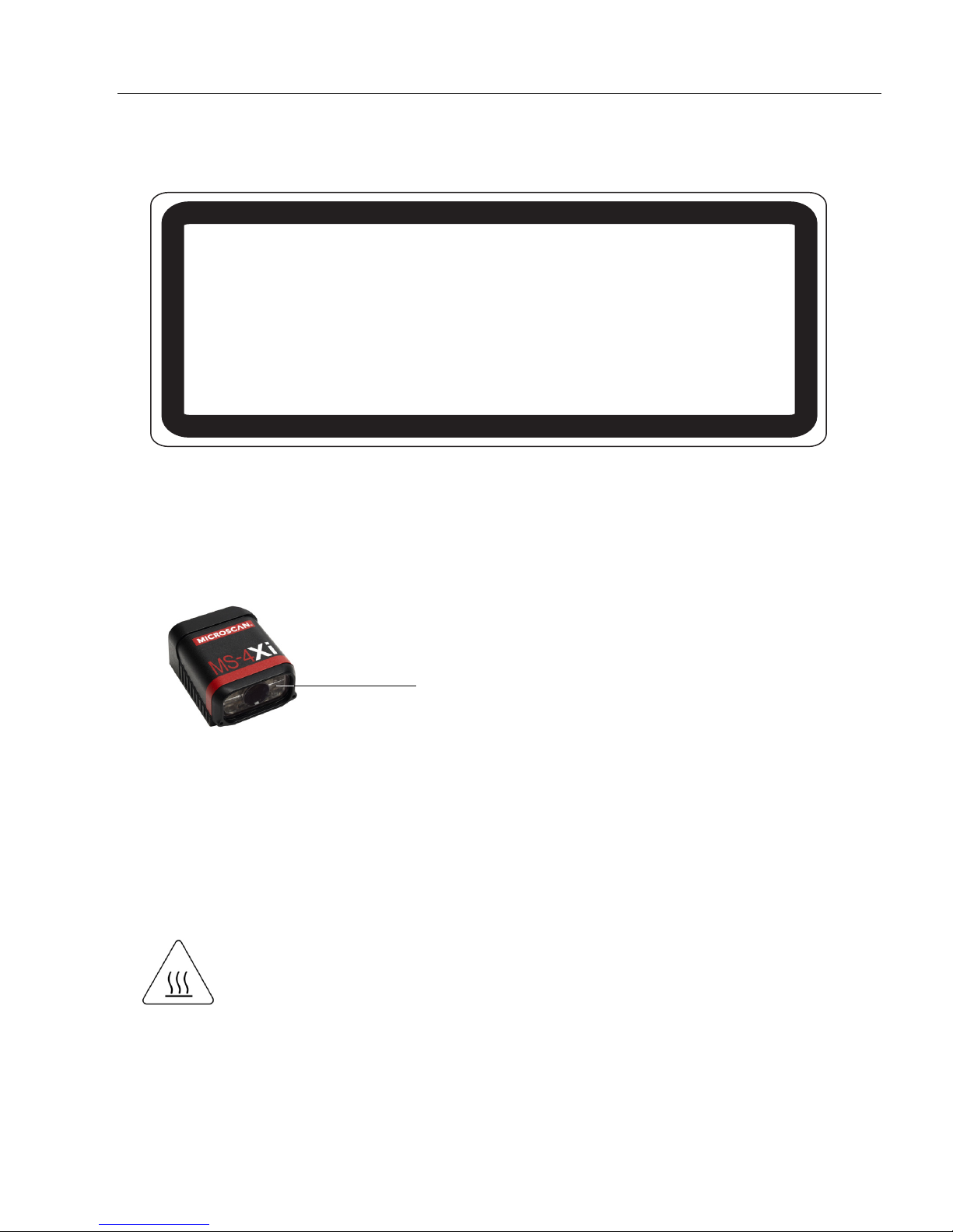
About the MS-4X Imager
About the MS-4Xi Imager
The key features of the MS-4Xi Imager are:
• Powerful X-Mode
• Ethernet TCP/IP connectivity
• Compatible with industrial M12 cabling
• Software-adjustable focus
• Support for both linear and 2D symbologies
• High-output LED illumination
• 10-30 VDC
• Optoisolated I/O
• EZ Button for setup and testing
• A blue target pattern that identifies the center point of the field of view
• A green flash (visible from all angles) to signal a successful read
• Compact size for easy integration into a wide variety of applications
™ decoding technology
MS-4Xi Communications
There are three ways to configure and test the MS-4Xi:
Microscan’s Windows-based
•
of use and visual responses to user adjustments.
• Serial commands, such as <K100,1>, that can be sent from ESP’s Terminal or another
terminal program.
•The EZ Button at the back of the imager.
ESP
(Easy Setup Program), which offers point-and-click
ease
viii MS-4Xi Imager User’s Manual
Page 9
Introduction
WARNING
LED LIGHT
DO NOT VIEW DIRECTLY WITH OPTICAL INSTRUMENTS
CLASS 1 LED PRODUCT
LED Output: .564 mW. Wavelength: 470 nm; 525 nm; 617 nm.
IEC 60825-1:1993+A1:1997+A2:2001
LED Aperture Window
Warning and Caution Summary
• Viewing the MS-4Xi’s LED output with optical instruments such as magnifiers, eye
loupes, or microscopes within a distance of 100 mm could cause serious eye injury.
• Maximum LED output: .564 mW.
• Wavelength: 470 nm; 525 nm; 617 nm.
• Location of the MS-4Xi’s LED aperture window:
CAUTION: Use of controls or adjustments or performance of procedures other than those
specified herein may result in hazardous radiation exposure.
IMPORTANT: The MS-4Xi is intended for connection to a UL-listed direct plug-in power unit
marked Class II and rated 24 VDC at 5 Watts, or greater if using electrical accessories.
European models must use a similarly rated Class I or Class II power supply that is certified
to comply with standard for safety EN 60950.
WARNING: Baseplate temperature may exceed 70° C at maximum operating
temperature and may cause burns. Use caution when handling.
MS-4X Imager User Manual ix
Page 10

Statement of Agency Compliance
Statement of Agency Compliance
The MS-4Xi has been tested for compliance with FCC (Federal Communications Commission)
regulations and has been found to conform to all applicable FCC Rules and Regulations.
To comply with FCC RF exposure compliance requirements, this device must not be co-located
or operate in conjunction with any other antenna or transmitter.
Changes or modifications not expressly approved by the party responsible for compliance
could void the user’s authority to operate the equipment.
The MS-4Xi
guidelines, and has been found to conform to applicable CE standards, specifically the
EMC requirements EN 55024:1998+A1:2001+A2:2003, ESD EN 61000-4-2, Radiated RF
Immunity EN 61000-4-3, ENV 50204, EFT EN 61000-4-4, Conducted RF Immunity EN
61000-4-6, EN 55022:1998+A1:2000+A2:2003 for Class A products, Class A Radiated
Emissions, and Class A Conducted Emissions.
The MS-4Xi has been tested by an independent electromagnetic compatibility laboratory in
accordance with the applicable specifications and instructions.
has been tested for compliance with CE (Conformité Européenne)
standards and
x MS-4Xi Imager User’s Manual
Page 11

Introduction
Statement of RoHS Compliance
All Microscan readers with a ‘G’ suffix in the FIS number are RoHS-Compliant. All compliant
readers were converted prior to March 1, 2007. All standard accessories in the Microscan Product
Pricing Catalog are RoHS-Compliant except 20-500013-01 and 98-000039-02. These products
meet all the requirements of “Directive 2002/95/EC” European Parliament and the Council of
the European Union for RoHS compliance. In accordance with the latest requirements, our
RoHS-Compliant products and packaging do not contain intentionally added Deca-BDE,
Perfluorooctanes
trace levels. To view the document stating these requirements, please visit:
http://eur-lex.europa.eu/LexUriServ/LexUriServ.do?uri=CELEX:32002L0095:EN:HTML
and
http://eur-lex.europa.eu/LexUriServ/LexUriServ.do?uri=OJ:L:2006:372:0032:0034:EN:PDF
Please contact your sales manager for a complete list of Microscan’s RoHS-Compliant products.
This declaration is based upon information obtained from sources which Microscan believes to be reliable, and
from random sample testing; however, the information is provided without any representation of warranty,
expressed or implied, regarding accuracy or correctness. Microscan does not specifically run any analysis on our
raw materials or end product to measure for these substances.
The information provided in this certification notice is correct to the best of Microscan’s knowledge at the date of
publication. This notice is not to be considered a warranty or quality specification. Users are responsible for
determining the applicability of any RoHS legislation or regulations based on their individual use of the product.
In regards to “RoHS Directive 2011_65_EU” Microscan produces Monitoring and Control Instruments as well as
Industrial Monitoring & Control Instruments as defined within the directive. Microscan has developed and is
implementing a RoHS2 compliance plan with the intention of bringing all active products listed in our current
marketing literature within full compliance as per the directive deadlines.
Key milestones for the transition plan are as follows:
• Complete internal product audit by July 2014.
• Initial “Monitoring and Control Instruments” RoHS2 compliant products available by December 2014
• Initial “Industrial Monitoring & Control Instruments” RoHS2 compliant products available by July 2015
• All new products introduced in 2015 are expected to be WEEE & RoHS2 compliant.
Microscan will mark the products with the ‘CE’ marking that complies with the RoHS2 process to acquire ‘CE’ certification
per the example given: Example >> Machinery directive + EMC directive + RoHS2 = Declaration of Conformity.
(PFOS) or Perfluorooctanic Acid (PFOA) compounds above the maximum
MS-4X Imager User Manual xi
Page 12

Statement of RoHS Compliance
xii MS-4Xi Imager User’s Manual
Page 13

Contents
Step 1 Check Hardware................................................................................................................1-2
Step 2 Connect the System ..........................................................................................................1-3
Step 3 Position Imager and Symbol..............................................................................................1-4
Step 4 Install ESP.........................................................................................................................1-5
Step 5 Select Model......................................................................................................................1-6
Step 6 Connect ............................................................................................................................. 1-7
Step 7 Locate the Symbol in the Field of View ............................................................................. 1-8
Step 8 Calibrate ......................................................................................................................... 1-10
Step 9 Test Read Rate .............................................................................................................. 1-11
Step 10 Configure the Imager in ESP........................................................................................ 1-12
Step 11 Save Configuration in ESP........................................................................................... 1-13
1 Quick Start
This section is designed to get your MS-4Xi up and running quickly, using the EZ button or
ESP (Easy Setup Program). Following these steps will allow you to get a sense of the
imager’s capabilities and to test sample symbols.
Detailed setup information for installing the imager into your actual application can be
found in the subsequent sections.
MS-4Xi Imager User’s Manual 1-1
Page 14
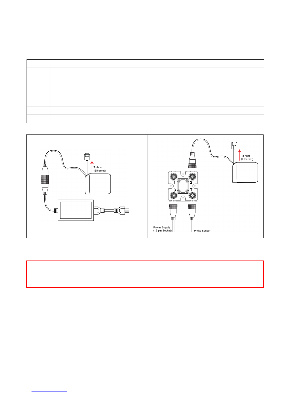
Check Hardware
Caution: Be sure that all cables are connected BEFORE applying power to the
system. Always power down BEFORE disconnecting any cables.
Ethernet Standalone with QX-1Ethernet Standalone without QX-1
1
3
1
2
3
4
Step 1 — Check Hardware
Item Description Part Number
FIS-1004-1X10G
1 MS-4Xi
2 QX-1 Interface Device 98-000103-02
3 Power Supply, M12 12-pin Socket, 1.3 m (Screw-On) 97-000003-03
4 Photo Sensor, M12 4-pin Plug, NPN, Dark On, 2 m 99-000020-02
(X = 1 for Low
Density, 2 for
Standard Density)
1-2 MS-4Xi Imager User’s Manual
Page 15
Quick Start
Caution: Be sure that all cables are connected BEFORE applying power to the
system. Always power down BEFORE disconnecting any cables.
Ethernet Standalone with QX-1Ethernet Standalone without QX-1
1
3
1
2
3
4
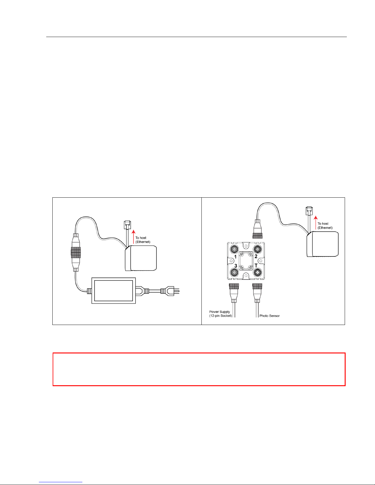
Step 2 — Connect the System
Ethernet Standalone without QX-1
• Connect the M12 (power and I/O) end of the imager’s cable to the power supply (3).
• Connect the RJ45 (Ethernet) end of the imager’s cable to the host.
• Plug in the power supply to apply power to the imager.
Ethernet Standalone with QX-1
• Connect the M12 (power and I/O) end of the imager’s cable to “2” on the QX-1 (2).
• Connect the RJ45 (Ethernet) end of the imager’s cable to the host.
• Connect the power supply (3) to “3” on the QX-1.
• Connect the photo sensor (4) to “T” on the QX-1.
• Plug in the power supply to apply power to the imager.
MS-4Xi Imager User’s Manual 1-3
Page 16
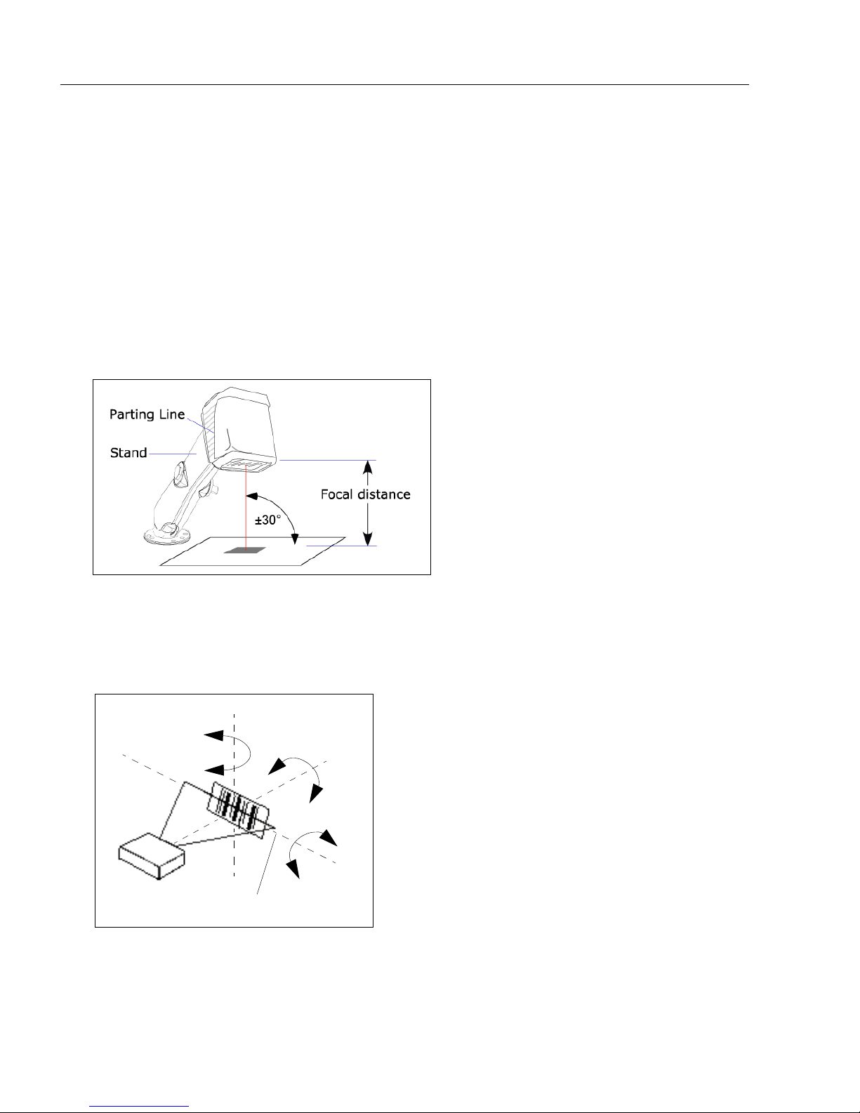
Position Imager and Symbol
Imager and Symbol Orientation
Imager and Symbol Orientation
Skew axis
Tilt
axis
Pitch
axis
Scan line
Step 3 — Position Imager and Symbol
• Position the imager at a distance from the symbol that matches the factory pre-set focal
distance. If your imager is pre-set at 4” (Standard Density), position the parting line 4”
from the symbol. If your imager is pre-set at 3” (Low Density), position the parting line 3”
from the symbol.
• Tip the imager relative to the symbol to avoid the glare of direct (specular) reflection.
The case parting line should be perpendicular to the plane of the symbol by either pitching
the symbol or the imager as shown.
• Position the imager in a place with as little ambient light as possible.
• Symbols can be rotated (tilted) at any angle; however, for best results symbols should
be aligned with the FOV (field of view).
• In the case of linear symbols, aligning the bars in the direction of their movement (“ladder”
orientation) will minimize the chances of blurring, and will produce better reads.
Important: Avoid excessive skew or pitch. Maximum skew is ±30°; maximum pitch is
±30°. The illustration below shows skew axis, pitch axis, and tilt axis.
Note: For accuracy of testing and performance, Microscan recommends using a mounting
arm adapter kit. Contact your Microscan sales manager for details about mounting arm
adapter kits and other accessories.
1-4 MS-4Xi Imager User’s Manual
Page 17

Quick Start
Step 4 — Install ESP
ESP Software can be found on the Microscan Tools Drive that is packaged with the MS-4Xi.
1. Follow the prompts to install ESP from the Tools Drive.
2. Click on the ESP icon to run the program.
Note: ESP can also be installed from the Download Center at
www.microscan.com.
Minimum System Requirements
• 233 MHz Pentium processor
• Windows 7 (32-bit or 64-bit), Vista (32-bit or 64-bit), XP, or 2000 operating system
• Internet Explorer 6.0 or higher
• 128 MB RAM or greater
• 80 MB hard drive space
• 800 x 600 minimum 256 color display (1024 x 768 32-bit color recommended)
MS-4Xi Imager User’s Manual 1-5
Page 18
Select Model
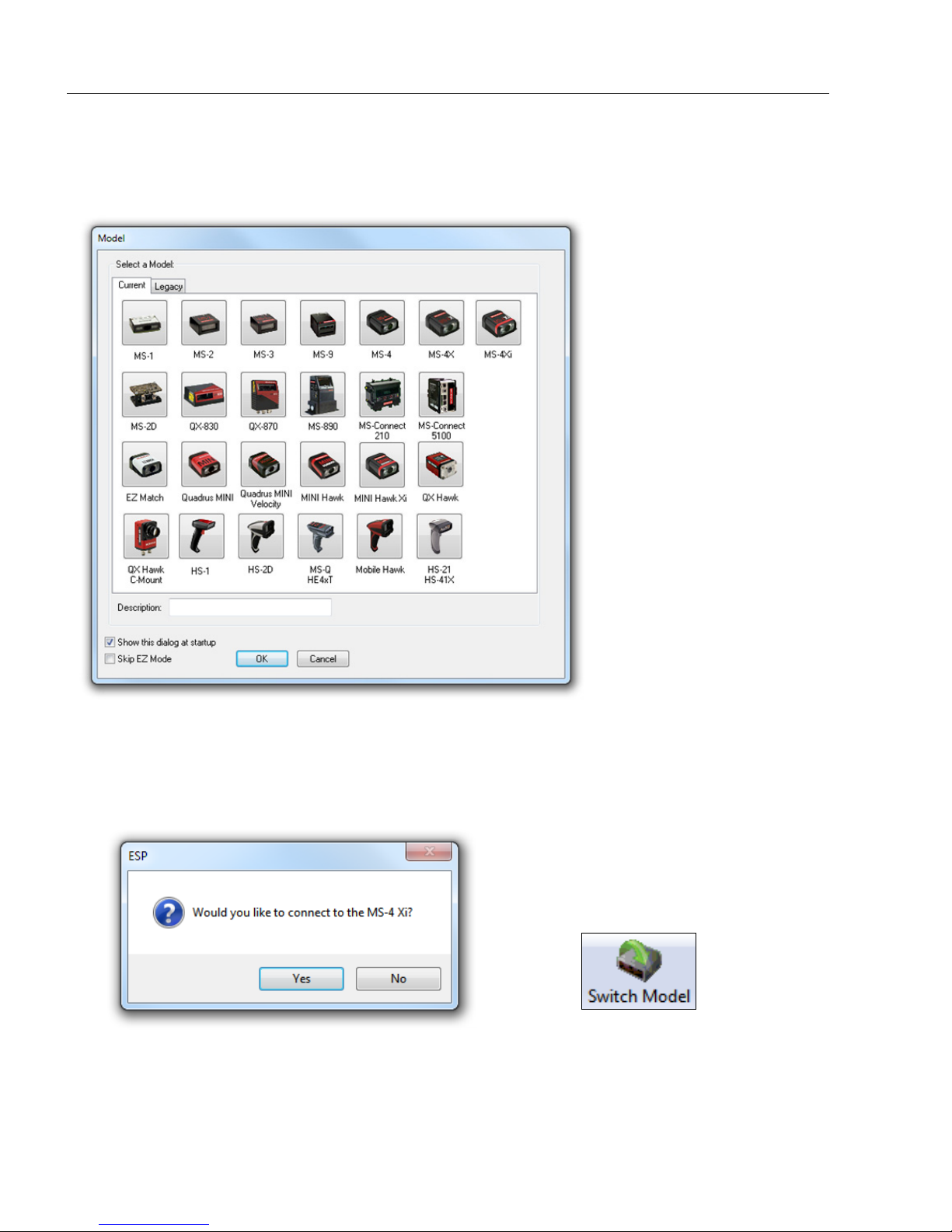
Step 5 — Select Model
When you start ESP, the following menu will appear:
1. Click the button showing the MS-4Xi.
2. Click OK.
Note: You can also double-click the MS-4Xi button to make your selection.
3. Click Yes when this dialog appears:
Note: If you need to select another model later, click the Switch Model button near
the top of the screen or use Model > New Model in the menu toolbar.
1-6 MS-4Xi Imager User’s Manual
Page 19
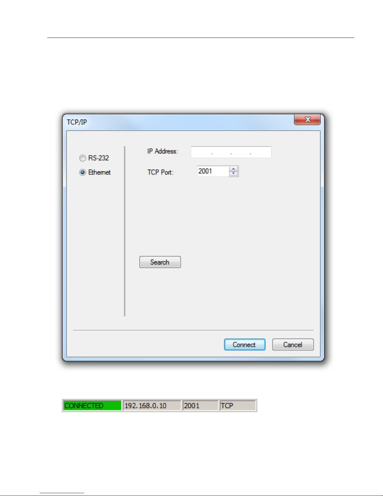
Step 6 — Connect
• Click Connect on the menu toolbar, and then select Connection Wizard.
• Select the communication interface required by your application.
• Configure settings as required by the application, and click Connect.
Quick Start
• When a connection is established, the green indicator in the status bar at the bottom
right of the screen will be visible:
Important: The imager is in Continuous Read Mode by default. For best connection
results, be sure that no decodable symbols are within the imager’s field of view while
attempting to connect.
MS-4Xi Imager User’s Manual 1-7
Page 20
Locate the Symbol in the Field of View
Center on object
in field of view.
Target pattern shown as it would appear between 3 and 6 inches.
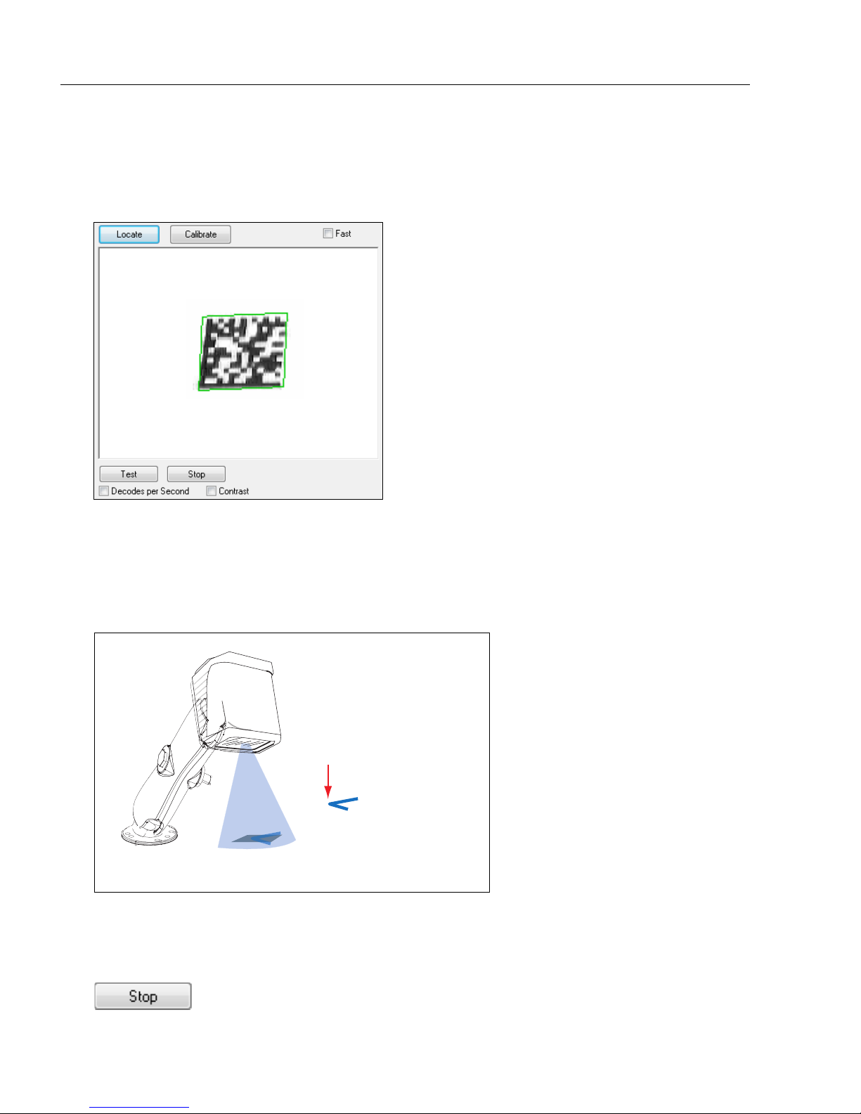
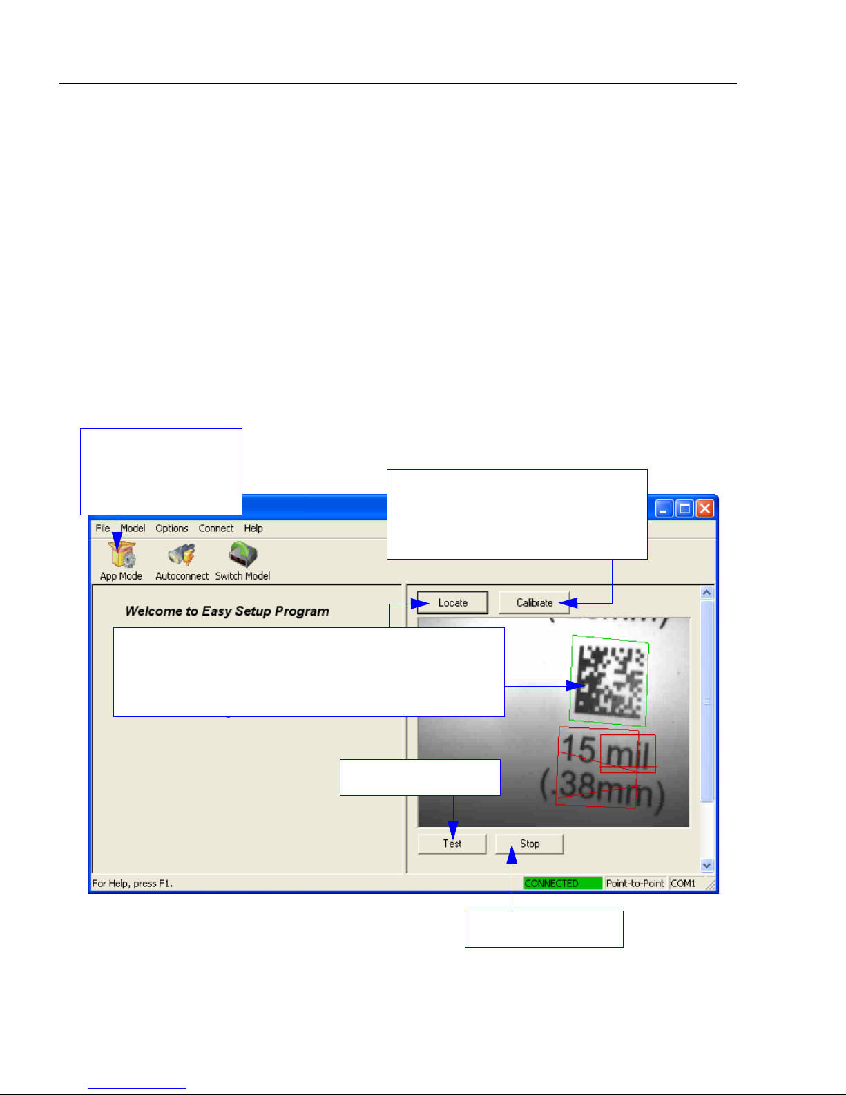
Step 7 — Locate the Symbol in the Field of View
Locate by ESP
•In ESP’s EZ Mode, click the Locate button to enable the blue target pattern.
The symbol in the field of view will appear in the video view beneath the Locate and
Calibrate buttons, and you will see the blue target pattern projected from the front of the
imager.
• Center the target pattern on the symbol.
At 2 to 3 inches, the pattern resembles an X. At 3 to 6 inches, the pattern resembles a V.
Important: The entire symbol should fall within the field of view (FOV) of the imager. The
field of view is what appears in ESP’s Locate/Calibrate window in EZ Mode.
• Click the Stop button to end the Locate function.
1-8 MS-4Xi Imager User’s Manual
Page 21
Quick Start
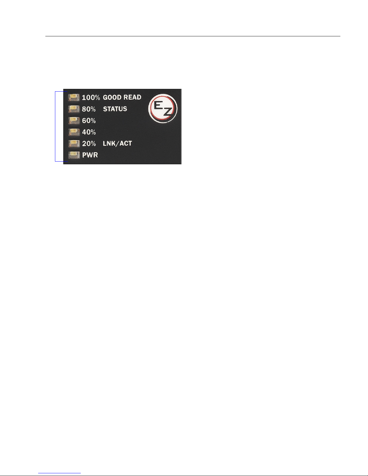
MS-4Xi Read Rate LEDs and
EZ Button
Locate by EZ Button
If you are not connected to a host computer, the EZ Button allows you to locate a symbol
in the imager’s field of view.
• Hold down the EZ Button for about one second and release when you hear one short
beep. The amber
from the front of the imager.
• Center the target pattern on the symbol.
20%
LED will illuminate, and you will see the blue target pattern projected
Note: To end all EZ Button functions, press the EZ Button once and quickly release.
MS-4Xi Imager User’s Manual 1-9
Page 22
Calibrate
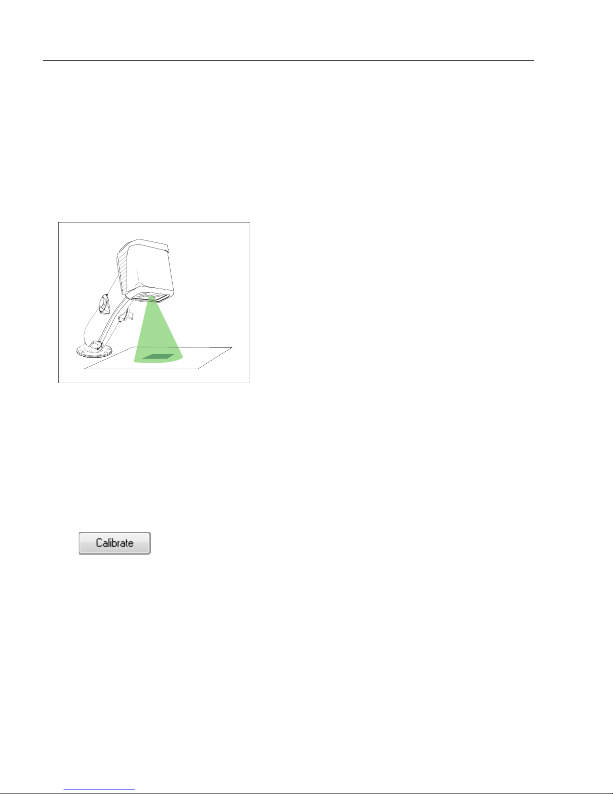
Step 8 — Calibrate
MS-4Xi settings can be adjusted automatically for optimum symbol decoding performance
either the EZ Button or by ESP.
During the calibration routine, the reader will flash its amber Read Rate percent LEDs and
red illumination LEDs while searching camera settings and determining the best configuration
for decoding symbol data. Upon successful completion of this routine, a green LED pattern
will flash brightly
and stop searching.
and illuminate the symbol. If unsuccessful, the imager will emit 5 short beeps
by
Calibrate by EZ Button
1. Hold down the EZ Button for about two seconds and release when you hear two
short beeps. The 20% and 40% LEDs will illuminate.
2. The imager will search camera settings to determine the best configuration for decoding
symbol data.
Note: To end all EZ Button functions, press the EZ Button once and quickly release.
Calibrate by ESP
1. Click the Calibrate button.
2. The imager will search camera settings to determine the best configuration for decoding
symbol data.
A successful calibration will display a green frame around the symbol, and the following
message will appear: “Uploading all reader parameters.” After a moment the symbol
data will be presented in the field below the image display window.
Calibrate by Serial Command
Send <@CAL> from a terminal program to begin calibration.
1-10 MS-4Xi Imager User’s Manual
Page 23
Quick Start
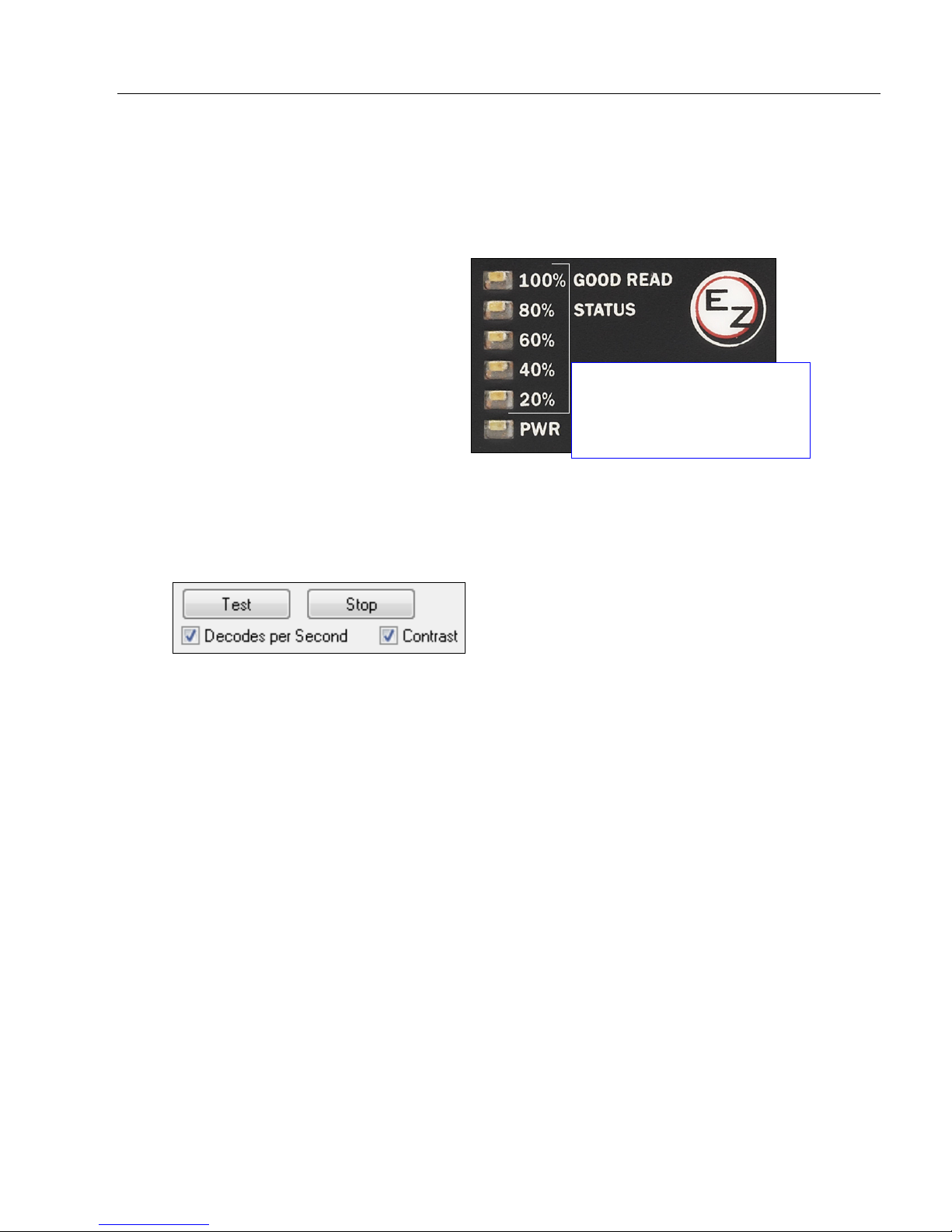
20%, 40%, 60%, 80%, 100%.
These LEDs represent the
percentage of Good Reads
per images captured.
Step 9 — Test Read Rate
Read Rate indicates the number of successful decodes per second achieved by the imager.
Test Read Rate by EZ Button
1. To start the Read Rate test, hold
down the EZ Button about three
seconds until you hear three
short beeps. The 20%, 40%, and
60% LEDs will illuminate.
While the symbol is being
inspected, the Read Rate LEDs
will indicate the corresponding
read rate percentage on the back
of the unit.
2. To end the Read Rate test, press the EZ Button and quickly release.
Test Read Rate by ESP
1. Click the Test button to start the Read Rate test and Stop to end it.
If a symbol has been successfully decoded, the symbol’s data and related features will
be presented in the field below the image display window. Also, while the symbol is
being inspected, the Read Rate LEDs will indicate the corresponding Read Rate
percentage on the back of the unit.
2. To end the test, click the Stop button.
Note: Read Rate can also be tested using the Read Rate interface in Utilities.
Test Read Rate by Serial Command
You can also start a test with the <C> or <Cp> command and end it with the <J> command.
MS-4Xi Imager User’s Manual 1-11
Page 24
Configure the Imager in ESP
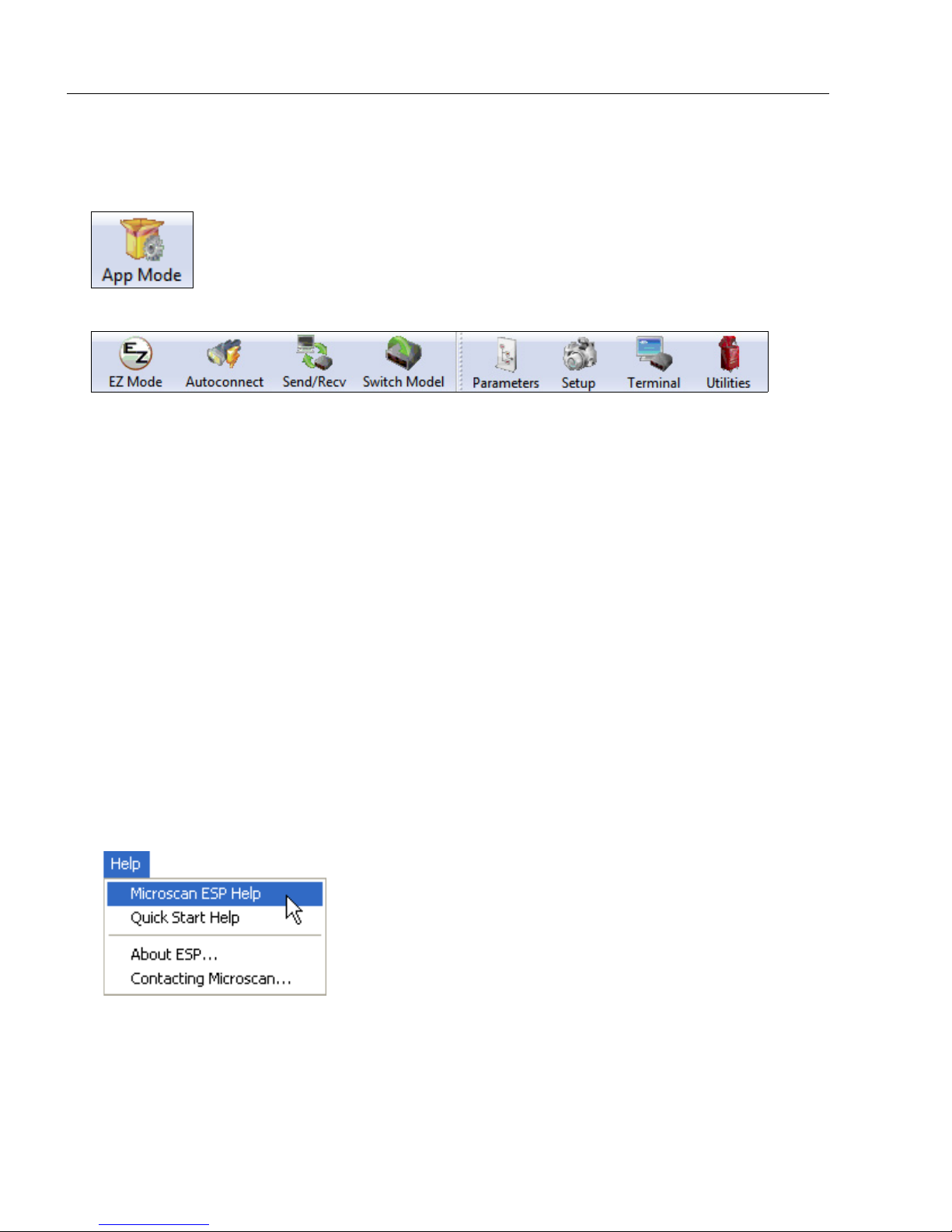
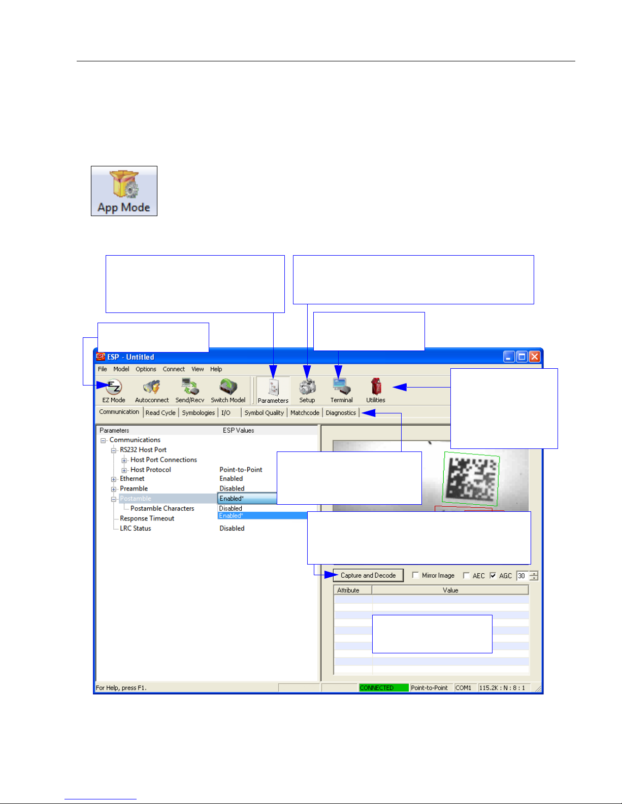
Step 10 — Configure the Imager in ESP
To make setup changes to the MS-4Xi, click the App Mode button.
The following modes are accessible by clicking the buttons in the first row of
• Click the EZ Mode button to return to EZ Mode.
• Click the Autoconnect button to establish communication.
• Click the Send/Recv button to send or receive commands.
• Click the Switch Model button to open the model menu, or to return to a previous model.
• Click the Parameters button to show the tabbed tree controls for Communication, Read
Cycle, Symbologies, I/O Parameters, Symbol Quality, Matchcode, and Diagnostics.
• Click the Setup button to access a Camera Setup tree control and Video view, and to
Evaluate image captures, Calibrate the imager, set the Window of Interest, fine-tune
capture settings and processing settings in the Configuration Database, set up output
filters and parse symbol data in Ordered Output and Output Format, and control multiple
read cycle functions in Dynamic Setup.
• Click the Terminal button to display tube or cap detection data or decoded symbol data,
and to send serial commands to the imager using text or macros.
• Click the Utilities button to test Read Rate, request or clear Counters, enable or disable
the imager or send output pulses in Device Control, determine the Differences from
Default in the current settings, add or remove master symbol data in Master Database,
and verify or update the imager’s Firmware.
App Mode
icons:
For further details, see ESP Help in the dropdown Help menu.
1-12 MS-4Xi Imager User’s Manual
Page 25
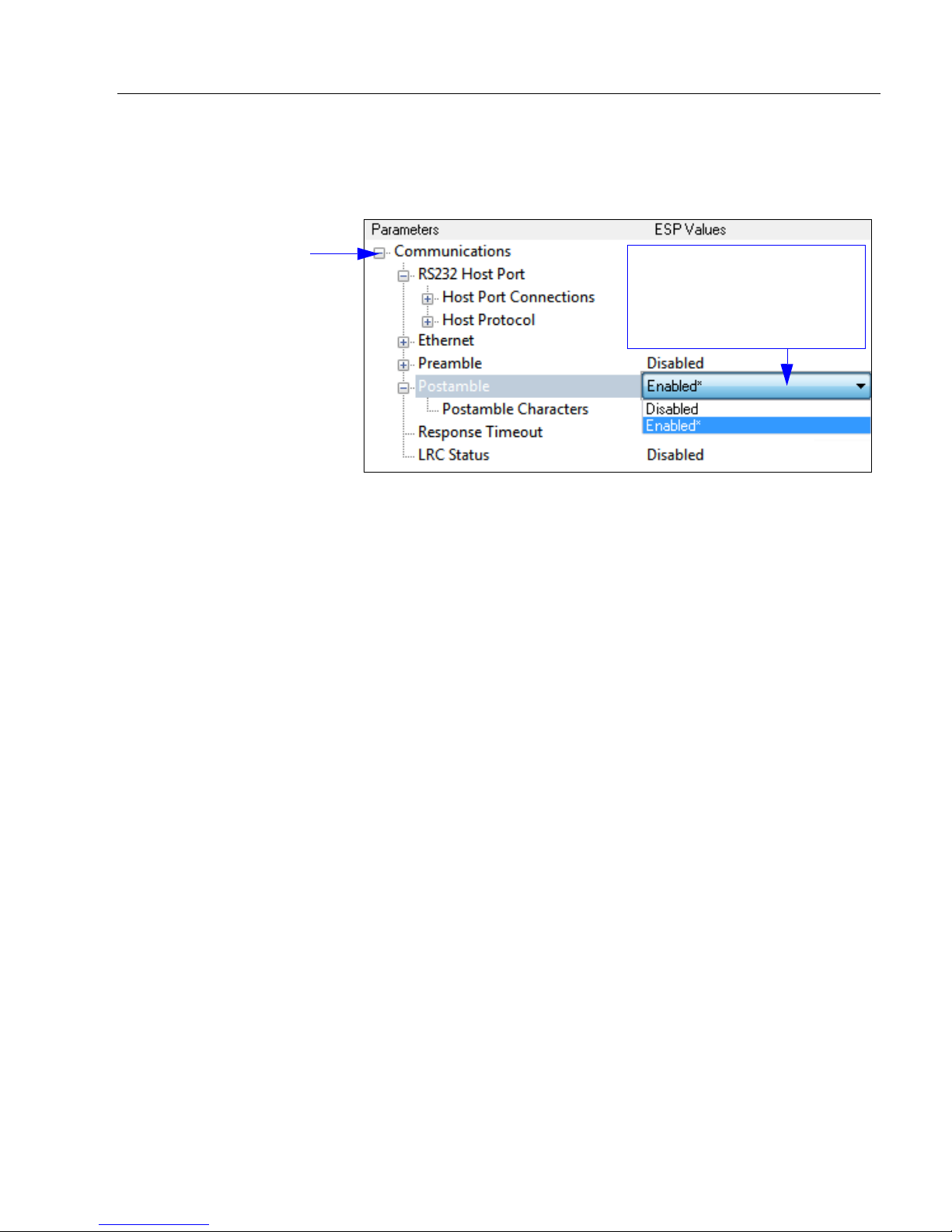
Step 11 — Save Configuration in ESP
1. Left-click on the +
to expand the
desired tree.
2. Double-click on the
desired parameter
and click once in the
selection box to view
options.
5. Right-click on the open
screen and select Save to
Reader to implement the
command in the imager.
4. Left-click again on the open
screen to complete your
selection.
3. Place your cursor in the
selection box, scroll down to
the setting you want to
change, and click once on
the setting.
To make changes to a configuration setting:
Quick Start
Saving Options
• Send, No Save. Changes will be lost when power is re-applied to the imager.
• Send and Save. This activates all changes in current memory and saves to the imager
for power-on.
MS-4Xi Imager User’s Manual 1-13
Page 26

Save Configuration in ESP
1-14 MS-4Xi Imager User’s Manual
Page 27

2 Using ESP
EZ Mode........................................................................................................................................2-2
Application Mode...........................................................................................................................2-3
Menu Toolbar................................................................................................................................2-4
View ............................................................................................................................................2-13
Navigating in ESP .......................................................................................................................2-14
Send/Receive Options ................................................................................................................2-15
Using EZ Trax .............................................................................................................................2-17
Contents
This section is designed to help you understand the basic structure and elements of ESP
(Easy Setup Program).
When you open ESP, unless otherwise specified in the ESP Preferences dialog accessible
from the Options heading on the menu toolbar, you will enter EZ Mode for initial setup.
From there, you can enter Application Mode (App Mode) and access several configuration
menus (Communications, Read Cycle, Symbologies, I/O Parameters, Symbol Quality,
Matchcode, and Diagnostics), a Camera setup interface, a Termin al interface, a Utilities
interface, and an Output Format interface.
ESP can be used to configure the MS-4Xi in three different ways:
•
Tree Controls:
specific element of imager operation. For example, the
Host Port Connections
Bits
, and
• Graphic User Interfaces: Imager settings can be configured using such point-and-click
tools as radio buttons, zoom in/zoom out sliders, spin boxes, check boxes, and drag-and-drop
functions.
• Terminal: ESP’s Terminal allows you to send serial configuration and utility commands
directly to the imager by typing them in the provided text field.
Each configuration menu contains a list of all option settings that pertain to that
Data Bits
Communications
option, and then a list of the sub-options
. Each of these sub-options is configurable by using dropdown menus.
Baud Rate, Parity, Stop
menu shows a
Information about using ESP in specific applications is provided in subsequent sections.
For
ESP
MS-4Xi Imager User’s Manual 2-1
system requirements, see
Minimum System Requirements
in
Quick Start
.
Page 28
EZ Mode
Starts Read Rate test.
Click Calibrate to begin the initial
calibration routine. Calbration is
explained at the left of the EZ Mode
screen, and also in Quick Start.
Click Locate to activate the MS-4Xi’s blue target pattern
LEDs. Center the target pattern on the symbol. The display
shows you where the symbol is located in the imager’s
field of view.
Ends Read Rate test.
Enter App Mode to
access configuration
trees and other setup
features.
EZ Mode
In
EZ Mode
to your imager,
instructions that will help you with positioning, testing, and calibration.
Test
Click the Test button to start the Read Rate test for a quick indication of the imager’s read
capabilities and the limits of your application. When Decodes per Second is unchecked,
the test will count the percentage of decodes relative to the number of actual scans. Click
Stop to end the test.
Calibrate
The calibration routine that will optimize the imager by comparing Read Rates at various
camera and image processing settings.
you are presented with the
EZ Mode
is the screen you will see. You will be provided with on-screen
Locate, Calibrate
, and
Test
options. After connecting
2-2 MS-4Xi Imager User’s Manual
Page 29
Using ESP
Open the Terminal
view.
Decoded symbol data
is shown in this table.
Return to EZ Mode.
Video, Evaluation, Calibration, Window of
Interest, Configuration Database, Ordered
Output, Output Format, Dynamic Setup
Click on tabs in this row to
access configuration trees
like the one shown here.
Communication, Read Cycle,
Symbologies, I/O Parameters,
Symbol Quality, Matchcode,
Diagnostics
Read Rate,
Counters,
Device Control,
Differences,
Master Database,
Firmware
Click Capture and Decode to read the
symbol in the field of view, and to see a high
resolution image capture of the symbol.
Application Mode
From EZ Mode, you can click on the App Mode button to access specific configuration
menus, Utilities tools, Camera setup, Output Format options, and a Terminal window
where serial commands can be entered.
Note: The App Mode and EZ Mode buttons appear in the same position to allow easy
switching between these primary modes.
Note: For specific information on any of the icons shown above in the operations bar or
configuration bar, see the corresponding sections of this manual.
MS-4Xi Imager User’s Manual 2-3
Page 30
Menu Toolbar
(Save to Imager)
(Receive Imager
Settings)
Menu Toolbar
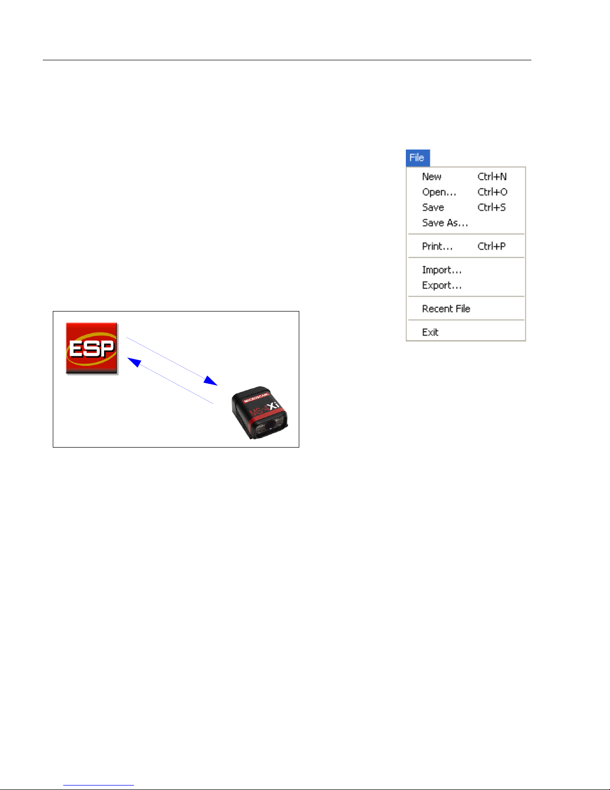
File > New
Whenever New is selected, the default configuration of ESP is
loaded.
Open/Save
When Save or Save As is selected, the ESP configuration is
saved to the host computer’s hard drive and available whenever
the same file is selected under Open.
Important: When you save menu changes to your hard drive,
these changes are not saved to your imager.
below shows how settings can be saved and received between
ESP and the imager, and ESP and the host hard drive.
The illustration
Import/Export
Import converts the ASCII settings from a text file to ESP configuration settings.
Export converts the active ESP configuration settings to an ASCII text file.
2-4 MS-4Xi Imager User’s Manual
Page 31

Using ESP
Model
In the Model menu you can select any of the models supported by ESP. When you choose
a different model, the connection to your present model will be terminated.
To connect to another model, select New Model, choose a new model from the menu that
appears, and click OK.
Note: When you save an ESP file, you are saving the settings of all the models defined in
that file.
MS-4Xi Imager User’s Manual 2-5
Page 32

Menu Toolbar
The Toolbar Style
options allow you to
determine how ESP
will display the mode
options in the two rows
at the top of the screen.
Options
The Options menu allows you to save memos and set up ESP
Preferences.
Note: Preferences will be saved and loaded into ESP whenever ESP
is opened next, whether or not you save the ESP file.
Preferences > General Tab
Reload Last File
At startup, reloads the last file saved to the host computer’s hard drive.
Show Model Prompt
At startup, shows the model menu displaying all supported readers.
Show Connect Prompt
At startup, displays the Would you like to connect to the MS-4Xi? prompt.
Receive After Connect
At startup, loads the imager’s settings into ESP. (This is not recommended if you want to
preserve your ESP settings for future use.)
Skip EZ Mode
At startup, skips EZ Mode and opens directly in App Mode.
Enable ‘Send and Save as Customer Defaults’
At startup, enables the Send and Save as Customer Defaults option in the Send/Recv
command.
2-6 MS-4Xi Imager User’s Manual
Page 33

Using ESP
Preferences > Terminal Tab
Show Non-Printable Characters
When Show Non-Printable Characters is enabled, characters such as “CRLF” will be
displayed in the Termi nal window. When Enhanced Format is checked, the characters
are displayed with more detailed formatting.
Change Keyboard Macros
Clicking the Change Keyboard Macros button brings
up the Function Keys dialog. In this dialog you can
select the desired function key and then enter your
macro keystrokes in the associated key map. For
example, to make Ctrl-F2 the keystroke to send a trigger
character, select F2, then in the Ctrl row, enter <trigger
character> and click OK. Then whenever the Ctrl-F2
keystroke is pressed, the trigger character will start the
read cycle.
Note: The F1 key is reserved for opening ESP Help and the F3 key is reserved for the
Find Next function.
Change Font
Allows you to modify the font used for decode data received from the imager on the
screen.
Term inal
Change Echo Font
Allows you to modify the font used for command characters typed into the Te rmin al view.
Enable Echo
Allows you to enter command characters in Terminal.
Display Incoming Data Even When Not in Focus
When Display Incoming Data Even When Not in Focus is enabled, data from the
imager will continue to appear in the terminal even when ESP is not the top window.
MS-4Xi Imager User’s Manual 2-7
Page 34

Menu Toolbar
Preferences > Bar Code Options Tab
The Bar Code Options dialog allows you to set the size of user-created symbols.
Sizing Information
Sets the bar width or module width (in
Example: A bar width of 18 is 0.018 inches.
2-8 MS-4Xi Imager User’s Manual
mils
, or thousandths of an inch) of user-created symbols.
Page 35

Using ESP
Preferences > Advanced Tab
The Auto Sync options at the top of the Advanced tab allow you to determine whether
Auto Sync will be enabled automatically in sections of ESP where it is used, or if it will ask
you before it enables Auto Sync functions.
Always Ask Before Auto Sync Occurs
If you check this option box, you are then able to determine what specific Auto Sync
functions will be enabled. Receive Settings from the Reader will automatically send the
imager’s settings to ESP when Auto Sync is enabled. Send ESP Settings to the Reader
will automatically send all imager configuration settings chosen in ESP to the imager. Do
Not Send or Receive Settings creates a condition in which Auto Sync will not automatically
send imager settings to ESP, or send ESP settings to the imager.
Show Target Pattern During Locate
Allows you to determine whether the blue LED target pattern will be on or off during the
Locate routine.
Show Target Pattern During Calibrate
Allows you to determine whether the blue LED target pattern will be on or off during the
Calibrate routine.
Use Higher Quality Images
Sets ESP to output images at a higher resolution than standard JPEG format.
Open Image after Save
When Open Image after Save is enabled, ESP automatically opens saved image captures.
Images can be saved from the Evaluation tab in the Camera view, or by right clicking an
image in any other image capture view and then saving.
Send XON with Autoconnect
Sends an
routine.
MS-4Xi Imager User’s Manual 2-9
XON (Begin Transmission
) command to the imager before starting the
Autoconnect
Page 36

Menu Toolbar
Preferences > Advanced Tab (cont.)
Ask to Save ESP File when Quitting
When enabled, prompts the user to save a .esp file when ending a session.
The .esp file will be saved in the location of your choice.
Connect to Readers via TCP/IP
When enabled, shows a TCP/IP option on the Connection Wizard.
Use Default Storage Location
When enabled, automatically stores data in ESP’s Application Data folder.
2-10 MS-4Xi Imager User’s Manual
Page 37

Using ESP
Document Memo
The information you type in the Document Memo field will appear in a context-sensitive text
box whenever your cursor hovers over the Document Memo item on the Options menu.
Model Memo
Similar to Document Memo, the information you type in the Model Memo field will appear
in a context-sensitive text box whenever your cursor hovers over the Model Memo item on
the Options menu. Memos created in Model Memo are specific to the model enabled
when the message was created.
Note:
Memos must be saved in a
If you do not save your current session, any memos that you have entered during the session
will be discarded, and will be unavailable in your next session.
MS-4Xi Imager User’s Manual 2-11
.esp
file if you want them to available in your next session.
Page 38

Menu Toolbar
Connect
The Connect dropdown menu allows the user to access the Connection Wizard, as well
as the Autoconnect dialog. Connect and Disconnect can also be performed directly
from the dropdown menu without opening a dialog.
Connection Wizard
To connect using the Connection Wizard:
• Click Connect on ESP’s menu toolbar, and then select Connection Wizard.
• Select the communication interface required by your application.
• Configure settings as required by the application, and click Connect.
• When a connection is established, the green indicator in the status bar at the bottom
right of the screen will be visible.
• If your RS-232 connection attempt fails, click the Auto Connect button to establish a
connection between the MS-4Xi and the host.
2-12 MS-4Xi Imager User’s Manual
Page 39

Using ESP
Choose a spatial
orientation for the
new symbol.
Create a caption
for the symbol
that matches the
encoded data, or
write your own
caption.
Drag specific configuration
values from the control tree
directly into this field to
encode new symbols.
The symbol you create
will be displayed in the
field at the bottom of the
Bar Code Dialog.
View
The View menu allows you to move quickly between interfaces without using the icon
buttons on the App Mode toolbar. It also allows you to access the Bar Code Dialog.
Bar Code Dialog
In the
Bar Code Dialog
you can create symbols by typing the text you wish to encode. This is a
useful tool for creating configuration symbols, allowing you to configure your reader by reading
the symbols you create.
MS-4Xi Imager User’s Manual 2-13
Page 40

Navigating in ESP
1. Left click on the + to
expand menu items.
2. Double-click the
desired parameter and
single-click in the
selection box to view
options.
3. Place your cursor in the
selection box, scroll
down to the setting you
want to change, and
single-click the setting.
4. Left click again on the open screen to complete the
selection.
5. Right click on the open screen and select Save to
Reader to implement the command in the imager.
You can send the command without saving it, or you
can send and save the command simultaneously.
The X denotes the
default option setting.
Navigating in ESP
To change imager settings, or to access the Utilities, Camera, Termi nal, or Output
Format views, click the App Mode button.
To return to EZ Mode, click the EZ Mode button.
To make changes to configuration settings in the control trees:
2-14 MS-4Xi Imager User’s Manual
Page 41

Using ESP
Send/Receive Options
To ac ces s Receive, Save, and Default options, click the Send/Recv button. You can also
access these options by right-clicking in any of the configuration views.
Receiving
From the Send/Recv menu, select Receive Reader Settings.
Caution: Do not select this option if you do not want to upload the imager’s settings. For
example, if your ESP file has a number of custom settings that you want to maintain and
download into the imager, these settings would be lost by choosing Yes.
This is useful if you want to receive (upload) the imager’s settings and save them as a file
for future use. For example, if your imager has settings that you do not want to change,
choosing Yes would allow you to load those settings to ESP and save them in an ESP file
for later retrieval.
Receiving the imager’s settings will also assure that you will not be subsequently saving
any unwanted changes that you or someone else has made previously in ESP.
Saving
Send, No Save (<A>)
Saves
memory.
Send and Save (<Z>)
Activates all changes in
current memory and saves
to the imager for power-on.
Send and Save as Customer Defaults (<Zc>)
Saves your default settings for quick retrieval.
This option will be visible only if you have checked Enable ‘Send and Save as Customer
Defaults’ in ESP Preferences.
ESP
settings to current
MS-4Xi Imager User’s Manual 2-15
Page 42

Send/Receive Options
Defaulting
When you select Default Current Menu Settings or Default all ESP Settings, you are
only defaulting the ESP settings.
Advanced Options
Send Current View
This is the same as
>
Send No Save
commands in the current configuration
tree are sent.
Save to Reader
except that only the
Send Current Command
This is the same as
View
, except that it saves only the
command that is currently selected.
Send Current
Add/Remove Exception
After you perform a
option, you may see a list of serial commands. These are commands that may be in your
imager’s firmware, but not included in, or different from, your current version of
You can edit these commands by double-clicking on them and changing them as needed.
It is important to note that these commands will be saved to your imager whenever you
send a Save to Reader command, or an <A> or a <Z> command.
Also, if there is a corresponding ESP menu item, the ESP Value column for that item will
be blank following a Receive Reader Settings command.
Receive Reader Settings
command1 and you click on the
Add Exception
ESP
.
1. From the Send/Recv button or by right-clicking in any blank section of a tree control view.
2-16 MS-4Xi Imager User’s Manual
Page 43

Using ESP
Using EZ Trax
For detailed information about using EZ Trax, refer to the Help menu in EZ Trax software,
or the EZ Trax Quick Start Guide, available on the Microscan Tools Drive.
For information about how to configure the MS-4Xi for use with EZ Trax, see Setting Up the
Imager for EZ Trax in Read Cycle.
MS-4Xi Imager User’s Manual 2-17
Page 44

Using EZ Trax
2-18 MS-4Xi Imager User’s Manual
Page 45

Contents
Communications by ESP .............................................................................................................. 3-2
Communications Serial Commands.............................................................................................. 3-3
Host Port Connections.................................................................................................................. 3-4
Host Port Protocol.........................................................................................................................3-5
ACK/NAK Options.........................................................................................................................3-6
Polling Mode Options....................................................................................................................3-7
Ethernet ........................................................................................................................................ 3-8
Response Timeout......................................................................................................................3-14
LRC Status..................................................................................................................................3-15
Protocol Configuration Examples................................................................................................3-16
ASCII Character Entry Modifier................................................................................................... 3-17
Preamble.....................................................................................................................................3-18
Postamble................................................................................................................................... 3-19
3 Communications
This section explains how to set up communications parameters with the host.
With Microscan’s ESP (Easy Setup Program), configuration changes can be made in the
ESP
menus and then sent and saved to the imager. The user can also send serial commands
to the imager via ESP’s Terminal window.
MS-4Xi Imager User’s Manual 3-1
Page 46

Communications by ESP
Click the Parameters
button and then the
Communication tab.
To open nested options,
single-click the +.
To change a setting, double-click the
setting and use your cursor to scroll
through the options.
Communications by ESP
3-2 MS-4Xi Imager User’s Manual
Page 47

Communications
Communications Serial Commands
Host Port Connections <K100,baud rate,parity,stop bits,data bits>
<
K126,
Ethernet
Ethernet TCP Ports <K127,TCP Port 1,TCP Port 2>
Host Port Protocol <K140,protocol,address>
Preamble <K141,status,preamble characters>
Postamble <K142,status,postamble characters>
Response Timeout <K143,response timeout>
LRC <K145,status>
ACK/NAK Options <K147,RES,REQ,STX,ETX,ACK,NAK>
Polling Mode Options <K148,RES,REQ,STX,ETX,ACK,NAK>
status,IP address,subnet,gateway,IP address mode>
MS-4Xi Imager User’s Manual 3-3
Page 48

Host Port Connections
Host Port Connections
The host port can be configured with RS-232 connections.
The following settings define the basic transmission speeds and digital standards that
ensure common formatting.
Baud Rate, Host Port
Usage: Can be used to transfer data faster or to match host port settings.
Definition: The rate at which the reader and host transfer data back and forth.
Serial Cmd: <K100,baud rate,parity,stop bits,data bits>
Default: 115.2K
Options: 0 = 600 1 = 1200 2 = 2400
3 = 4800 4 = 9600 5 = 19.2K
6 = 38.4K 7 = 57.6K 8 = 115.2K
9 = 230K
Parity, Host Port
Usage: Only changed if necessary to match host setting.
Definition: An error detection routine in which one data bit per character is set to 1 or 0
so that the total number of bits in the data field is either even or odd.
Serial Cmd: <K100,baud rate,parity,stop bits,data bits>
Default: None
Options: 0 = None 1 = Even 2 = Odd
Stop Bits, Host Port
Usage: Only changed if necessary to match host setting.
Definition: One or two bits added to the end of each character to indicate the end of
the character.
Serial Cmd: <K100,baud rate,parity,stop bits,data bits>
Default: One
Options: 0 = One 1 = Two
Data Bits, Host Port
Usage: Only changed if necessary to match host setting.
Definition: One or two bits added to the end of each character to indicate the end of
the character.
Serial Cmd: <K100,baud rate,parity,stop bits,data bits>
Default: Eight
Options: 0 = Seven 1 = Eight
3-4 MS-4Xi Imager User’s Manual
Page 49

Communications
Host Port Protocol
Usage: In general, the point-to-point protocols will work well in most applications.
They require no address and must use RS-232 communications standards.
Definition: Protocols define the sequence and format in which information is transferred
between the reader and the host.
Serial Cmd: <K140,protocol,address>
Default: Point-to-Point
Options: 0 = Point-to-Point
4 = ACK/NAK
5 = Polling Mode
Note: In all protocol modes, the preamble <K141> and postamble <K142> character
strings can be used to frame the decode data, and both are included in calculating the
LRC (Longitudinal Redundancy Check).
Point-to-Point (Standard)
Usage: Used only with RS-232.
Definition: Standard Point-to-Point requires no address and sends the data to the
host whenever it is available, without a request or handshake from the host.
Serial Cmd: <K140,0>
ACK/NAK
Definition: See the ACK/NAK Options command <K147>.
Serial Cmd: <K140,4>
Polling Mode
Definition: See the Polling Mode Options command <K148>.
Serial Cmd: <K140,5>
Poll Address
Serial Cmd: <K140,protocol,address>
Default: 1
Options: 1 to 50
1 = Poll address 0x1C, Select address 0x1D
2 = Poll address 0x1E, Select address 0x1F
...
50 = Poll address 0x7E, Select address 0x7F
MS-4Xi Imager User’s Manual 3-5
Page 50

ACK/NAK Options
ACK/NAK Options
Definition:
Serial Cmd: <K147,RES,REQ,STX,ETX,ACK,NAK>
These parameters take effect for
port and are completely independent of the
The imager always follows the protocol in both directions (to and from the
host). There is no option to disable it from either direction.
ACK/NAK <K140,4>
Polling Mode Options <K148>
on the main RS-232
RES-NAK Defaults
RES: (Reset) 00 (disabled)
REQ: (Request) 00 (disabled)
STX: (Start of Text) 00 (disabled)
ETX: (End of Text) 00 (disabled)
ACK: (Acknowledge) 06
NAK: (Negative Acknowledge) 15
The following are general outlines of the ACK/NAK protocol. Items that are framed by
brackets ( [ ] ) can either be disabled or enabled. LRC does not include STX, but it does
include preamble, postamble, and ETX.
Symbol Data Output
TX to host: [STX] [preamble] SYMBOL DATA [postamble] [ETX] [LRC]
Response from host: ACK/NAK. Sent when LRC, ETX, postamble, or timeout (waiting
for more data) are detected (if REQ is disabled) depending on what is enabled.
.
Commands from Host to Imager
TX to Imager: [STX] <command> [ETX] [LRC]
Response from Imager: ACK/NAK. Sent when LRC, ETX, or command-ending angle
bracket ‘>’ are received, depending on what is enabled.
Command Response from Imager to Host
TX to host: [STX] [preamble] COMMAND RESPONSE DATA [postamble] [ETX] [LRC]
Response from host: ACK/NAK. Sent when LRC, ETX, postamble, command-ending
angle bracket ‘>’, or timeout (waiting for more data) are detected, depending on what is
enabled.
As with Polling Mode <K140,5>, the imager can optionally perform the REQ and RES
event sequences in ACK/NAK mode. If the sender does not receive an ACK or NAK, it will
send REQ to request such a response (if enabled). When the sender receives an ACK, too
many NAKs, or times out (if already enabled), it will send a RES (if enabled) to terminate the
transaction.
Note:
See
ACK/NAK Data Flow Examples
3-6 MS-4Xi Imager User’s Manual
for sample ACK/NAK communication scenarios.
Page 51

Communications
Polling Mode Options
Definition: These parameters only take effect for Polling Mode <K140,5> on the main
RS-232 port and are completely independent of the ACK/NAK Options
<K147>.
The values of protocol characters can be changed, but the protocol events
cannot be disabled. The polling mode address is configured in the <K140>
command (see Poll Address).
If RS-232 is enabled, <K102,0>, Polling Mode will operate as a Point-to-
Point polling protocol. This is because the RS-232 transmitter is always left
on when enabled.
Serial Cmd: <K148,RES,REQ,STX,ETX,ACK,NAK>
RES-NAK Defaults
RES: (Reset) 04
REQ: (Request) 05
STX: (Start of Text) 02
ETX: (End of Text) 03
ACK: (Acknowledge) 06
NAK: (Negative Acknowledge) 15
Note: See Polling Mode Data Flow Examples for sample Polling Mode communication
scenarios.
MS-4Xi Imager User’s Manual 3-7
Page 52

Ethernet
Ethernet
Enables or disables Ethernet connectivity in the imager.
IP Address
Enter the IP address of the imager in this field.
3-8 MS-4Xi Imager User’s Manual
Page 53

Subnet
Enter the Subnet address of the imager in this field.
Communications
Gateway
Enter the Gateway address of the imager in this field.
MS-4Xi Imager User’s Manual 3-9
Page 54

Ethernet
IP Address Mode
Determines how the imager’s IP address will be defined.
Static
In Static Mode, the imager uses the user-defined IP address entered in ESP.
DHCP
In DHCP Mode, the imager automatically acquires the IP address, Subnet, and Gateway
addresses from a DHCP or BOOTP server.
3-10 MS-4Xi Imager User’s Manual
Page 55

TCP Port 1
Communications
One of two TCP ports for Ethernet communication with the imager. The default setting is
Symbol Data Output
Enables or disables decoded symbol data output from the imager.
2001
.
Extra Symbol Information
Enables or disables extra symbol information output from the imager.
Diagnostics Output
Enables or disables diagnostics output from the imager.
External Source Processing Mode
Enables or disables processing of commands or data from sources external to the imager.
Command
Command enables command processing in the imager.
Data
Data enables Ethernet TCP Port 1 as a data source port.
Note: The data path between in the source port and out the source port is always two-way.
Data is copied from source data ports and all those source ports’ data is transmitted to the
destination port, and from the destination port to the source port.
MS-4Xi Imager User’s Manual 3-11
Page 56

Ethernet
TCP Port 2
One of two TCP ports for Ethernet communication with the imager. The default setting is
Symbol Data Output
Enables or disables decoded symbol data output from the imager.
2003
.
Extra Symbol Information
Enables or disables extra symbol information output from the imager.
Diagnostics Output
Enables or disables diagnostics output from the imager.
External Source Processing Mode
Enables or disables processing of commands or data from sources external to the imager.
Command
Command enables command processing in the imager.
Data
Data enables Ethernet TCP Port 2 as a data source port.
Note: The data path between in the source port and out the source port is always two-way.
Data is copied from source data ports and all those source ports’ data is transmitted to the
destination port, and from the destination port to the source port.
3-12 MS-4Xi Imager User’s Manual
Page 57

Search and Configure Mode
After the imager is in full use in an
application, you may want the
imager to continue to appear in
the Search response list for future
searches. This can help prevent
disruption of the system that may
occur is ESP were to show only
unconfigured units.
Communications
Search and Configure Mode
is intended primarily for initial setup of an imager in a network.
This parameter controls whether or not the imager will respond to ESP’s Search function in
the Ethernet TCP/IP connect dialog section of the Connection Wizard:
Changes to this parameter are saved to NOVRAM and are set to default on power on.
A Reset <A> is required for settings to take effect.
Important: Once this setting is Disabled, ESP will only be able to connect to the imager if
you know the IP address and enter it in the IP Address field of the Ethernet TCP/IP connect
dialog. Search and Configure Mode can be re-enabled by defaulting the imager.
Enabled
When enabled, Search and Configure Mode will find the imager and settings can be
changed.
Timed Window
When Timed Window is selected, Search and Configure Mode will find the imager and
settings can be changed, but only 60 seconds from the last reset. After 60 seconds,
Search and Configure Mode will be disabled.
MS-4Xi Imager User’s Manual 3-13
Page 58

Response Timeout
Response Timeout
Usage: Only used when a response is required from the host. The reader can be
set to wait indefinitely by setting Response Timeout to zero.
Definition: The time that the imager will wait before timing out if ACK, NAK, and ETX
are enabled, and a host response is expected.
Serial Cmd: <K143,response timeout>
Default: 12 (in 1 ms increments)
Options: 0 to 255 (A zero (0) setting causes an indefinite wait.)
3-14 MS-4Xi Imager User’s Manual
Page 59

Communications
LRC Status
(Longitudinal Redundancy Check)
Usage: Used when extra data integrity is required.
Definition: An error-checking routine that verifies the accuracy of transmissions. It is
the exclusive OR of all characters following the STX (start of text) up to and
including the
of all the characters in a transmission are cumulatively added in a column
and each resulting odd integer is assigned a 1 and each even integer a 0
(two 1s = 0, two 0s = 0, a 1 and a 0 = 1). The extra LRC character is then
appended to the transmission, and the receiver (usually the host) performs
the same addition and compares the results.
Serial Cmd: <K145,status>
Default: Disabled
Options: 0 = Disabled 1 = Enabled
ETX
(end of text). What this means is that the binary representation
MS-4Xi Imager User’s Manual 3-15
Page 60

Protocol Configuration Examples
Protocol Configuration Examples
Point-to-Point (Main Port)
<K100,8,0,1,1> Baud Rate: 115.2K; Parity: None; Stop Bits: 2; Data Bits: 8
<K140,0> Point-to-Point
<K102,0> RS-232 enabled
Polling Mode (Main Port)
<K100,4,0,1,1> Baud Rate: 9600; Parity: None; Stop Bits: 2; Data Bits: 8
<K140,5,23> Polling Mode; Address: 23
<K102,0>
<K143,30> 30 ms Response Timeout
“User-Defined” Polling Mode (Main Port)
<K100,4,0,1,1> Baud Rate: 9600; Parity: None; Stop Bits: 2; Data Bits: 8
<K140,5,12> Polling Mode; Address: 12
<K148,,08,09,18,0B,0C,0D> Default RES (0x04), REQ=0x08; EOT=0x09; STX=0x18;
<K102,0> RS-232 Point-to-Point polling
<K143,40> 40 ms Response Timeout
RS-232 Point-to-Point polling
ETX=0x0B; ACK=0x0C; NAK=0x0D
ACK/NAK (Main Port)
<K100,9,0,1,1> Baud Rate: 230K; Parity: None; Stop Bits: 2; Data Bits: 8
<K140,4> ACK/NAK
<K147,,,01,1B,2E,1F> Default RES and REQ (00, disabled); STX=0x01; ETX=0x1B;
ACK=0x2E; NAK=0x1F
<K102,0> RS-232 enabled
<K143,50> 50 ms Response Timeout
3-16 MS-4Xi Imager User’s Manual
Page 61

Communications
ASCII Character Entry Modifier
Commands that require ASCII text fields, such as Preamble and Postamble commands,
can be sent to the imager as hex pairs (see ASCII Table for conversions).
Serial Cmd Format: <Knnnh,00-FF>
To enter ASCII fields as hex values (00 to FF), add a lower-case h directly after the command’s
K
number, and then enter the hex value that corresponds with the desired ASCII character.
Example:
Consider the Postamble command:
Serial Cmd: <K142,status,postamble character(s)>
Imagine that your application requires the ASCII character > to be the postamble in your
symbol decode output.
The ASCII characters <, >, and
postamble in your symbol decode output, enter the Postamble command as follows:
<K142h,,3E>
Note that the “status” field contains only a
changed is the “postamble character(s)” field. (See Serial Configuration Command
Conventions for a more detailed explanation of this command shortcut.)
, can only be entered as hex pairs. So, to make > the
, . This is because the only field that is being
MS-4Xi Imager User’s Manual 3-17
Page 62

Preamble
Preamble
Preamble Status
Usage: Useful for identifying and controlling incoming data. For example, defining
the preamble as a carriage return and a line feed causes each decoded
message to be displayed on its own line.
Definition: Defines a one to four character data string that can be added to the front of
the decoded data.
Serial Cmd: <K141,status,preamble character(s)>
Default: Disabled
Options: 0 = Disabled 1 = Enabled (within any protocol)
Preamble Characters
Serial Cmd: <K141,status,preamble character(s)>
Default: ^M corresponds to: carriage return.
Options: To enter control characters within a serial command, hold down the Ctrl
key while typing the desired character.
Example: <K141,1,CNTL-m> to enter the control character ^M.
Important:
For <: <K141h,,3C>
For >: <K141h,,3E>
, : <K141h,,2C>
For
The ASCII characters <, >, and , can only be entered as hex pairs:
3-18 MS-4Xi Imager User’s Manual
Page 63

Communications
Postamble
Postamble Status
Usage: Useful for identifying and controlling incoming data. For example, defining
the postamble as a carriage return and a line feed causes each decoded
message to be displayed on its own line.
Definition: Allows the user to enable or disable up to four postamble characters that
can be added to the end of the decoded data.
Serial Cmd: <K142,status,postamble character(s)>
Default: Enabled
Options: 0 = Disabled 1 = Enabled (within any protocol)
Postamble Characters
Serial Cmd: <K142,status,postamble character(s)>
Default: ^M^J corresponds to: carriage return/line feed.
Options: To enter control characters within a serial command, hold down the control
key while typing the desired character.
Example: <K142,1,CNTL-m CNTL-j> to enter ^M^J.
Important:
For <: <K142h,,3C>
For >: <K142h,,3E>
, : <K142h,,2C>
For
The ASCII characters <, >, and , can only be entered as hex pairs:
MS-4Xi Imager User’s Manual 3-19
Page 64

Postamble
3-20 MS-4Xi Imager User’s Manual
Page 65

4 Calibration
Calibration Serial Commands .......................................................................................................4-2
Calibration Overview..................................................................................................................... 4-2
Calibration Options .......................................................................................................................4-3
Calibration by ESP..................................................................................................................... 4-10
Initiating Calibration ................................................................................................................... 4-12
Additional Notes about Calibration............................................................................................. 4-18
Contents
This section shows the MS-4Xi’s calibration options, and explains the different ways that
those options can be configured.
MS-4Xi Imager User’s Manual 4-1
Page 66

Calibration Serial Commands
Calibration Serial Commands
Calibration Options <K529,gain,shutter speed,symbol type,WOI framing,WOI
margin,line scan height,processing>
Autocalibrate
<
@CAL
>
Calibration Overview
Autocalibration is one of the most powerful features of the MS-4Xi. The calibration process
can be initiated by serial command, EZ button, or ESP user interface.
When the imager enters calibration, it runs through an optimization cycle that sets the ideal
parameters for reading symbols at the highest possible level of performance. Autocalibration
can be specially configured to optimize specific parameters, such as focus, gain, shutter
speed, and symbol type.
The calibration process consists of five separate phases: quick focus, search pass, focus
pass, medium pass, and fine-tune pass. During this process the imager quickly locates
configuration setup, defines a calibration range for the configuration parameters, and then
tunes those parameters for optimal performance.
4-2 MS-4Xi Imager User’s Manual
Page 67

Calibration
Calibration Options
This command specifies the operation of the imager’s calibration feature. The default
configuration is set up to perform calibration on gain, focus, and symbol type. The
default shutter speed setting is disabled, because not all applications require shutter
speed, and when it is required, the application-specific settings tend to vary widely.
Note: Background Color is part of the calibration process regardless of the calibration
setup. After successful completion of the calibration routine, the background color will be
set to the appropriate value, depending on the symbol in the field of view. The Illumination
Brightness parameter is not part of the calibration process, and it must be configured
appropriately prior to calibration.
Gain
Definition: When enabled, gain will be calibrated to provide the best available image
quality and performance.
When disabled, gain is fixed and is not part of the calibration process.
Serial Cmd: <K529,gain,shutter speed,symbol type,WOI framing,WOI margin,line
scan height,processing>
Default: Enabled
Options: 0 = Disabled 1 = Enabled
Shutter Speed
Definition:
Serial Cmd: <K529,gain,shutter speed,symbol type,WOI framing,WOI margin,line
Default: Disabled
Options: 0 = Disabled 1 = Enabled
Note:
various line speeds. The configurations shown depend on the imager’s optical configuration,
and on symbol element size.
The following table shows general guidelines for shutter speed configurations based on
Shutter Speed Line Speed
0 - 250 static
250 - 750 5” / sec
750 - 1500 10” / sec
1500 - 2000 15” / sec
2000 - 2500 20” / sec
Unless an application is a static setup, the shutter speed setting should be
configured by the user based on the application. For dynamic applications, the
user should configure the shutter speed setting so the calibration process can
optimize the gain for that setting.
scan height,processing>
2 = Fast Shutter
MS-4Xi Imager User’s Manual 4-3
Page 68

Calibration Options
Disabled (Shutter Speed)
When this feature is disabled, the shutter speed is fixed and is not part of the calibration
process.
Enabled (Shutter Speed)
When this feature is enabled, shutter speed will be calibrated to provide the best possible
image quality and performance.
Fast Shutter
The calibration process will concentrate on achieving the fastest possible shutter setting that
will still provide good performance. The image quality or contrast may not be as good as
what would be achieved with the Enabled setting. The calibration process is not designed to
choose the fastest shutter speed that can decode a symbol, but rather to optimize for the
fastest shutter speed that still provides good image quality.
4-4 MS-4Xi Imager User’s Manual
Page 69

Calibration
Symbol Type
Serial Cmd: <K529,gain,shutter speed,symbol type,WOI framing,WOI margin,line
scan height,processing>
Default: Enabled
Options: 0 = Disabled 1 = Enabled
Disabled
When this feature is disabled, only the currently-enabled symbologies will be considered
during the calibration process.
Enabled
When this feature is enabled, autodiscrimination will be in effect during the calibration
process. All symbologies that are readable by the imager except PDF417 and Pharmacode
will be considered during calibration. Any new symbologies successfully decoded during
calibration will remain enabled at the end of the process. All enabled symbologies will
remain enabled.
For example, assume that only Code 39 is enabled at the beginning of calibration. If a
Code 128 symbol is read during calibration, then Code 128, as well as Code 39, will be
enabled after the calibration process is complete.
MS-4Xi Imager User’s Manual 4-5
Page 70

Calibration Options
Configured WOI
Starting WOI
After Decode
Calibration Passed
Calibration Failed
Configured WOI
After Decode
Calibration Passed Calibration Failed
Window of Interest (WOI) Framing
Definition: If a WOI framing mode is enabled, it will set the camera WOI to a full-size
image when calibration begins. Once a symbol is decoded, the camera
WOI will be zoomed-in both vertically and horizontally (regardless of
which WOI mode is enabled) to include the symbol plus an additional
margin area. This is done to accelerate the calibration process.
When a successful calibration process is completed, the camera WOI
will be adjusted according to the mode enabled. Otherwise, the original
WOI configuration will be retained.
Serial Cmd: <K529,gain,shutter speed,symbol type,WOI framing,WOI margin,line
scan height,processing>
Default: Disabled
Options: 0 = Disabled 1 = Row and Column
2 = Row 3 = Column
4 = Straight Line 5 = Straight Line Framed
If WOI framing is not enabled, the current WOI configuration will be used until a symbol
has been decoded. After a symbol is decoded, the WOI is framed exactly as it would be if
a WOI framing mode was enabled. When the calibration process is complete, the original
WOI configuration is restored. Refer to the diagram below:
4-6 MS-4Xi Imager User’s Manual
Page 71

Calibration
Disabled
When this feature is disabled, the Window of Interest is not modified after the calibration
process is complete.
Row and Column
If the calibration process is successful, the Window of Interest will be modified to frame the
symbol as well as an additional margin area around the symbol, determined by the WOI
Margin parameter. Refer to the diagram below:
Column
If the calibration process is successful, the Window of Interest columns will be modified to
vertically frame the symbol, plus an additional margin area around the symbol, determined
by the WOI Margin parameter. Refer to the diagram below:
Row
I
f the calibration process is successful, the Window of Interest rows will be modified to horizontally
frame the symbol, plus an additional margin area around the symbol, determined by the
Margin
MS-4Xi Imager User’s Manual 4-7
parameter. Refer to the diagram below:
WOI
Page 72

Calibration Options
Straight Line
This feature is intended for use with linear symbologies. If the calibration process is successful
the orientation of the symbol is determined and the Window of Interest is modified according
to the symbol orientation. The scan line orientation is determined to be vertical if the
symbol tilt is between 225° and 315°, or between 45° and 135°. Otherwise, the scan line
will be horizontal.
If the symbol is vertical, the image column size will be set by the scan height parameter,
and will be configured for full row resolution. If the symbol is horizontal, the image row size
will be set by the scan height parameter, and will be configured for full column resolution.
The scan line will be centered in the middle of the symbol. If the symbol is tilted such that
the scan line will not pass completely through the symbol, the scan width will be adjusted
to include the entire symbol. Refer to the diagram below:
,
Straight Line Framed
This parameter is the same as “Straight Line”, except that the Window of Interest will also
frame the scan line on the symbol length as well. The scan line includes the symbol plus
an additional margin area determined by the WOI Margin parameter.
4-8 MS-4Xi Imager User’s Manual
Page 73

Window of Interest (WOI) Margin
Calibration
Definition:
Serial Cmd: <K529,gain,shutter speed,symbol type,WOI framing,WOI margin,line
Default: 75 (pixels)
Options: 20 to 1280
Sets the margin size that is applied to the calibrated symbol. This parameter
is expressed in number of pixels. If the margin causes the image to exceed
the maximum image size, it will be reduced accordingly.
scan height,processing>
Line Scan Height
Definition: This parameter is only used with the Straight Line modes. It sets the scan
height of the straight-line image, and it is expressed in number of pixels.
Serial Cmd: <K529,gain,shutter speed,symbol type,WOI framing,WOI margin,line
scan height,processing>
Default: 64 (pixels)
Options: 3 to 1024
Processing
Definition: This setting defines the amount of time and effort the imager will spend
attempting to decode a symbol for each parameter configuration.
Serial Cmd: <K529,gain,shutter speed,symbol type,WOI framing,WOI margin,line
scan height,processing>
Default: Medium
Options: 0 = Low 1 = Medium
2 = High 3 = Definable
Low
The imager will spend a low amount of effort attempting to decode the given symbol for
each parameter configuration.
Medium
The imager will spend a medium amount of effort attempting to decode the given symbol
for each parameter configuration.
High
The imager will spend a high amount of effort attempting to decode the given symbol for
each parameter configuration.
Definable
The processing time for each image frame is defined by the Image Processing Timeout
parameter <K245>.
MS-4Xi Imager User’s Manual 4-9
Page 74

Calibration by ESP
Before and After tabs give the user an authentic
representation of the difference in what the imager
“sees” before and after the calibration routine.
Determines the
amount of time
and effort the
imager will spend
attempting to
decode a symbol
for each parameter
configuration.
(Low, Medium,
High, Definable).
Focus, Shutter,
Gain, and Image
Quality values
are all tracked in
real-time during
the calibration
process.
Initiates the
calibration
routine.
Cancels the
calibration
process, if
necessary.
The Window of Interest section of the Calibration interface allows the user to make precise adjustments
to WOI Framing, WOI Margin (in pixels), and the scan height of the straight-line image (in pixels).
Dropdown menu of 1D and 2D symbologies, and a check
box for enabling or disabling Composite symbologies.
Gain, Shutter Speed, and
Focal Distance (Capture
Settings) are all configurable
in the Calibration interface.
Calibration by ESP
ESP’s Calibration view incorporates all the functionality of the <K529> (Calibration
Options) command in a single easy-to-use, intuitive interface. This calibration process
allows the user much finer control of individual parameters than the calibration routine in
EZ Mode or on the Video tab.
Before/During Calibration
4-10 MS-4Xi Imager User’s Manual
Page 75

After Calibration
Notice the improved image
resolution after the calibration
process is complete.
The calibration
progress bar
indicates that
the process has
been completed.
Saves the optimal configuration parameters
determined by calibration results.
The Focus, Shutter,
Gain, and Quality
indicator bars
remain stationary at
the end of calibration
to provide a visual
reference for the
final values of these
four parameters.
Calibration
MS-4Xi Imager User’s Manual 4-11
Page 76

Initiating Calibration
Initiating Calibration
Calibration can be initiated by serial command, the EZ button, or from the Calibration
interface in
In ESP, the Calibrate button starts the calibration routine.
ESP
. A symbol must be in the imager’s field of view during the calibration process.
To initiate calibration by serial command, enter the serial command
such as
and readability.
ESP
’s
Termina l
interface.
<@CAL>
is a calibration routine that emphasizes contrast
<@CAL>
from a terminal,
See Calibrate by EZ Button for the EZ button calibration procedure.
4-12 MS-4Xi Imager User’s Manual
Page 77

Calibration
Search Pass
Calibrated
Successfully
Focus Pass
Medium Pass
Fine-Tune Pass
Calibration Progress Indicators
During the calibration process, the imager has a number of ways to communicate its progress to the user. The following three types of feedback are the primary ways that the
imager communicates calibration progress.
Read Rate LEDs
When calibration is initiated through a serial command or the EZ Button, the imager’s
Read Rate LEDs indicate calibration progress as follows:
LEDs Calibration Progress
20% Search Pass in progress.
20%, 40% Focus Pass in progress.
20%, 40%, 60% Medium Pass in progress.
20%, 40%, 60%, 80% Fine-Tune Pass in progress.
20%, 40%, 60%, 80%, 100% Calibrated Successfully (holds for green flash duration).
MS-4Xi Imager User’s Manual 4-13
Beeper/Green Flash
The beeper and green LED flash are used to indicate calibration status as shown in the
table below:
Indicator Status
2 quick beeps Calibration has started.
5 quick beeps Calibration has failed.
1 long beep Calibration has been completed successfully.
1 sec. Green Flash Calibration has been completed successfully.
Page 78

Initiating Calibration
Calibration Progress Output to Terminal
When initiated by serial command or EZ button, the autocalibration operation will output
progress and process information to a terminal if the system is configured to do so.
Terminal
Depending upon how the calibration options are configured, the autocalibration process
can have up to 5 steps (Quick Focus, Search Pass, Focus Pass, Medium Pass, Fine-Tune
Pass). Calibration data is shown in a simple table format under 8 category headings, each
of which are defined below.
Heading Definition
Prog Progress indicator with a range of 0 - 100. Indicates percent complete.
Rating Rating indicator; higher ratings are more favorable.
Decode Number of successful decodes for the pass.
Quality Quality indicator; higher ratings are more favorable.
Focus Focus position under operation.
Shutter Shutter setting under operation.
Gain Gain setting under operation.
Locate Time required to locate symbol, expressed in milliseconds.
Calibration Progress Output Examples (Terminal)
Quick Focus
This mode is only run if Quick Focus calibration mode is enabled. Quick Focus calibration
mode is designed to quickly locate the focus setting for an object at the center of the
imager’s field of view. There is no terminal output for this operation.
Search Pass
The purpose of Search Pass is to decode a symbol in as few configurations as possible
during calibration. This process is designed to quickly identify symbology type, and any
image processing parameters that are already calibrated, as well as determining focus
position.
Running Search Pass
Prog Rating Decode Quality Focus Shutter Gain Locate
12 0 0 0 313 250 0 0
14 0 0 0 313 250 9 0
16 0 0 0 313 250 18 0
18 2174 1 72 313 250 27 24
4-14 MS-4Xi Imager User’s Manual
Page 79

Calibration
Focus Pass
The purpose of
This is accomplished by determining the inside and outside focus positions and then recording
the center position as the desired focal position.
Prog Rating Decode Quality Focus Shutter Gain Locate
38 0 0 0 353 250 0 0
38 0 0 0 353 250 9 0
38 4256 2 48 353 250 18 5
38 0 0 0 409 250 0 0
38 4236 2 28 409 250 9 5
38 0 0 0 447 250 0 0
38 4236 2 28 447 250 9 4
38 0 0 0 492 250 0 0
38 4232 2 24 492 250 9 4
38 0 0 0 536 250 0 0
38 2128 1 24 536 250 9 5
38 0 0 0 572 250 0 0
38 0 0 0 572 250 9 0
38 2144 1 40 572 250 18 4
38 0 0 0 601 250 27 0
38 0 0 0 601 250 36 0
38 0 0 0 601 250 45 0
38 0 0 0 601 250 45 0
38 0 0 0 601 250 45 0
38 0 0 0 601 250 45 0
42 4280 2 72 297 250 45 6
42 4280 2 72 283 250 45 5
42 4280 2 72 270 250 45 5
42 4280 2 72 258 250 45 5
42 4280 2 72 247 250 45 5
42 4280 2 72 236 250 45 6
42 4280 2 72 227 250 45 5
42 4280 2 72 217 250 45 5
42 4280 2 72 209 250 45 6
42 4280 2 72 200 250 45 6
46 0 0 0 601 250 45 0
Focus Pass
is to determine the optimal focal position of the optical system.
Running Focus Pass
Inside Focus = 200; Outside Focus = 572; Center Focus = 386
MS-4Xi Imager User’s Manual 4-15
Page 80

Initiating Calibration
Medium Pass
The theory behind Medium Pass is to develop a readable range from which to dial in a
decoded symbol.
Running Medium Pass
Prog Rating Decode Quality Focus Shutter Gain Locate
51 4216 2 8 386 250 0 5
53 8436 4 20 386 250 4 4
55 6336 3 24 386 250 8 4
57 8448 4 32 386 250 12 4
59 8456 4 40 386 250 16 5
61 8464 4 48 386 250 20 4
63 8472 4 56 386 250 24 5
65 8488 4 72 386 250 28 5
67 8504 4 88 386 250 32 5
69 8512 4 96 386 250 36 5
71 8528 4 112 386 250 40 6
73 8584 4 168 386 250 44 5
75 8644 4 228 386 250 48 5
Rating List (Best):
Rating = 8606; Focus = 386; Shutter = 250; Gain = 48
Rating = 8581; Focus = 386; Shutter = 250; Gain = 44
Rating = 8553; Focus = 386; Shutter = 250; Gain = 40
Rating = 8527; Focus = 386; Shutter = 250; Gain = 36
Rating = 8505; Focus = 386; Shutter = 250; Gain = 32
Rating = 8488; Focus = 386; Shutter = 250; Gain = 28
Rating = 8476; Focus = 386; Shutter
= 25
0; Gain = 24
4-16 MS-4Xi Imager User’s Manual
Page 81

Calibration
Fine-Tune Pass
The theory behind Fine-Tune Pass is to dial in a decoded symbol based on the range
supplied by the Medium Pass.
Running Fine Tune Pass
Prog Rating Decode Quality Focus Shutter Gain Locate
77 6416 3 104 386 250 38 7
79 6424 3 112 386 250 39 6
81 6424 3 112 386 250 40 6
84 6432 3 120 386 250 41 6
86 6448 3 136 386 250 42 5
88 6464 3 152 386 250 43 5
90 6476 3 164 386 250 44 5
93 6488 3 176 386 250 45 5
95 6506 3 194 386 250 46 6
97 6524 3 212 386 250 47 5
100 6538 3 226 386 250 48 6
Rating List (Best):
Rating = 6527; Focus = 386; Shutter = 250; Gain = 48
Rating = 6517; Focus = 386; Shutter = 250; Gain = 47
Rating = 6505; Focus = 386; Shutter = 250; Gain = 46
Rating = 6491; Focus = 386; Shutter = 250; Gain = 45
Rating = 6476; Focus = 386; Shutter = 250; Gain = 44
Rating = 6462; Focus = 386; Shutter = 250; Gain = 43
Rating = 6449; Focus = 386; Shutter = 25
Calibration PASSED.
0; Gain = 42
MS-4Xi Imager User’s Manual 4-17
Page 82

Additional Notes about Calibration
Additional Notes about Calibration
The following conditions apply to the imager’s calibration process. Some of these items
are noted at various points throughout this section, or in other sections of the imager’s
documentation.
1. A symbol must be in the imager’s field of view during the calibration process.
2. The Illumination Brightness parameter <K514> is not part of the calibration process.
3. Background Color <K451> is calibrated.
4. If Window of Interest Framing is enabled, the WOI will be set to full frame when
calibration begins. If WOI Framing is disabled, the current WOI configuration will be
used for the Search Pass.
5. If Symbol Type is enabled for calibration (Autodiscriminate), then Interleaved 2 of 5
Range Mode Status (Interleaved 2 of 5) <K472>
Interleaved 2 of 5 symbols to be decoded. If an Interleaved 2 of 5 symbol is decoded
during calibration, then code length # 1 will be set to the decoded symbol length at the
end of calibration. Otherwise, the symbol lengths will be restored to their original
configurations.
6. Pharmacode is not calibrated.
7.
All symbol types that were enabled before calibration will still be enabled after calibration.
For example, if Data Matrix ECC 200 was enabled before calibration, and the calibration
routine was performed on a Code 128 symbol, then after calibration is completed both
Data Matrix ECC 200 and Code 128 will be enabled.
8. The calibration process does not modify the global Composite status <K453>. The
global Composite status must be configured properly before calibration.
9. If the user requires calibration of a stacked symbology <K482>, <K483>, or <K484>,
that symbology must be enabled and configured appropriately before calibration.
10. UPC Supplementals will be disabled during calibration.
11. The Search process will use the configurable Window of Interest for image captures.
However, when the search process is completed, the WOI will be reduced to include
only the symbol of interest and some additional boundary area.
will be enabled. This allows variable-length
4-18 MS-4Xi Imager User’s Manual
Page 83

Contents
Read Cycle by ESP ......................................................................................................................5-2
Read Cycle Serial Commands......................................................................................................5-3
Read Cycle Setup......................................................................................................................... 5-4
Multisymbol................................................................................................................................... 5-5
Trigger Mode and Filter Duration.................................................................................................. 5-6
External Trigger Polarity ............................................................................................................. 5-11
Serial Trigger ..............................................................................................................................5-12
Start Trigger Character (Non-Delimited) ..................................................................................... 5-13
Stop Trigger Character (Non-Delimited) ..................................................................................... 5-14
End of Read Cycle...................................................................................................................... 5-15
Capture Mode.............................................................................................................................5-17
Capture Timing ........................................................................................................................... 5-21
Image Processing Timeout ......................................................................................................... 5-23
Image Storage ............................................................................................................................ 5-24
Minimum Good Reads ................................................................................................................5-26
Setting Up the Imager for EZ Trax..............................................................................................5-27
5 Read Cycle
After you’ve established communications and completed basic read rate testing, you will
need to address the spatial and timing parameters associated with your application. This
section explains those parameters.
MS-4Xi Imager User’s Manual 5-1
Page 84

Read Cycle by ESP
To change a setting,
double-click the
setting and use your
cursor to scroll
through the options.
To open nested options,
single-click the +.
Click the Parameters
button and then the
Read Cycle tab.
Read Cycle by ESP
5-2 MS-4Xi Imager User’s Manual
Page 85

Read Cycle Serial Commands
Read Cycle
Trigger Mode/Filter Duration
Serial Trigger Character <K201,serial trigger character>
External Trigger State <K202,external trigger state>
End of Read Cycle <K220,end of read cycle,read cycle timeout>
Minimum Good Reads <K221,minimum good reads>
Multisymbol <K222,number of symbols,multisymbol separator>
Start Trigger Character <K229,start character>
Stop Trigger Character <K230,stop character>
Capture Timing <K242,time before first capture,time between first and second
Image Storage <K244,image storage type,image store mode>
Image Processing Timeout <K245,image processing timeout>
<K200,trigger mode,leading edge trigger filter,trailing edge
trigger filter>
captures,,,,,,,,time between seventh and eighth captures>
MS-4Xi Imager User’s Manual 5-3
Page 86

Read Cycle Setup
Read Cycle Setup
Setting up read cycle and triggering parameters will involve a series of decisions based on
your particular application, as follows:
1. Select the number of symbols to be read in a single cycle. The MS-4Xi can read multiple
symbols in a single image frame.
2. Decide on the trigger type to be used: if serial, choose a serial character; if external,
choose either Level or Edge.
3. Designate how the read cycle should end (Timeout, New Trigger, Last Frame).
4. Select Capture Mode, Continuous Mode, or Rapid Mode.
5. Select Number of Captures (if in Rapid Capture Mode).
6. Set the Time Before First Capture and Time Between Captures, if any.
Note: The imager’s camera captures images at a rate of about 16/second (based on a
1280 x 1024 image). The capture rate increases as frame sizes decrease.
Note: If you need to set up your MS-4Xi for use with EZ Trax software, see Setting Up the
Imager for EZ Trax.
5-4 MS-4Xi Imager User’s Manual
Page 87

Read Cycle
Multisymbol
Usage: Multisymbol is commonly used in shipping applications where a shipping
symbol contains individual symbols for part number, quantity, etc. This
feature allows on trigger to pick up all the symbols.
Definition: Multisymbol allows the user to define up to 100 symbols that can be read
in a single read cycle.
Conditions: The following conditions apply:
• Each symbol must be different to be read, unless in Rapid Capture
Mode, configured for “triggered capture”.
• The maximum number of characters in a read cycle is 3,000 for all
symbols.
• All No Read messages are posted at the end of the data string, unless
output filtering is enabled.
• If more than one symbol is within the field of view at the same time,
symbol data may not be displayed in the order of appearance.
•
If
Matchcode Type
Read 1 Output, the imager will behave as if Number of Symbols were
set to 1, regardless of the user-defined configuration.
is set to
Sequential
or if
Trigger
is set to
Continuous
Number of Symbols
Definition: Number of Symbols is the number of different symbols that can be read in
a single read cycle.
Serial Cmd: <K222,number of symbols, multisymbol separator>
Default: 1
Options: 1 to 100
Multisymbol Separator
Usage: Used to delimit or separate data fields with a user defined character.
Definition:
Serial Cmd: <K222,number of symbols,multisymbol separator>
Default: , (comma)
Options: Any available ASCII character.
Important:
For <: <K222h,,3C>
For >: <K222h,,3E>
, : <K222h,,2C>
For
Note: If No Read messages are disabled and there are No Reads occurring, separators
will only be inserted between symbol data outputs.
Any valid ASCII character, inserted between each symbol read when Multisymbol
is set to any number greater than 1.
The ASCII characters <, >, and , can only be entered as hex pairs:
MS-4Xi Imager User’s Manual 5-5
Page 88

Trigger Mode and Filter Duration
Trigger Mode and Filter Duration
Trigger Mode
Definition: The Trigger is the event that initiates a read cycle.
Note: When calibrating the imager or testing read rate, the current trigger
setting will be disregarded.
Serial Cmd: <K200,trigger mode,leading edge trigger filter,trailing edge trigger filter>
Default: Continuous Read
Options: 0 = Continuous Read
1 = Continuous Read 1 Output
2 = External Level
3 = External Edge
4 = Serial Data
5 = Serial Data and Edge
Continuous Read
Usage: Continuous Read is useful in testing symbol readability or reader functions.
It is not recommended for normal operations.
Definition: In Continuous Read, trigger input options are disabled, the imager is
always in the read cycle, and it will attempt to decode and transmit every
capture. If a single symbol stays within read range for multiple read cycles,
its data will be transmitted repeatedly until it leaves the read range.
The imager sends replies to serial commands that require responses when
symbol data is transmitted, or read cycle timeout is enabled and a timeout
occurs and at least one captured image has been processed. Depending
on the combination of enabled symbologies, the imager may take longer
than the timeout to process a captured image.
Note: When to Output
Read.
Serial Cmd: <K200,0>
5-6 MS-4Xi Imager User’s Manual
and
No Read
options have no affect on
Continuous
Page 89

Read Cycle
Continuous Read 1 Output
Usage: Continuous Read 1 Output can be useful in applications where it is not
feasible to use a trigger and all succeeding symbols contain different
information. It is also effective in applications where the objects are presented
by hand.
Definition: In Continuous Read 1 Output the imager self-triggers whenever it
decodes a new symbol or a timeout occurs.
If End of Read Cycle is set to Timeout and the symbol doesn’t change,
the output is repeated at the end of each timeout period. For example, if
Timeout
and repeats the output at intervals of one second for as long as it continues
to capture the symbol.
If End of Read Cycle is set to New Trigger, the imager will send the current
symbol data immediately, but only once. A new symbol appearing in the
imager’s range will be read and sent immediately, provided it is not identical
to the previous symbol.
Serial Cmd: <K200,1>
Caution: In automated environments, Continuous Read 1 Output is not recommended
because there is typically no reliable way to verify that a symbol was missed.
Note: If Trigger Mode is set to Continuous Read 1 Output, the imager will behave as if
Number of Symbols were set to 1, regardless of the user-defined configuration.
is set to one second, the imager sends the symbol data immediately
MS-4Xi Imager User’s Manual 5-7
Page 90

Trigger Mode and Filter Duration
Initiate Read Cycle:
Object #1, moving in front of the
detector beam, causes a
change in the trigger state,
which initiates the read cycle.
End Read Cycle:
The same object, moving out of
the detector beam, causes
another change in the trigger
state, which ends the read cycle.
Initiate Read Cycle:
Object # 1, moving in front of the
detector beam, causes a change in
the trigger state, which initiates the
read cycle.
Initiate Second Read Cycle:
Object # 2, moving in front of the
detector beam, causes another
change in the trigger state. This signal initiates a new read cycle and
ends the previous read cycle unless
Timeout
is enabled and a good read
or timeout has not occured.
External Level
Usage: This mode is effective in an application where the speeds of the conveying
apparatus are variable and the time the imager spends reading each object
is not predictable. It also allows the user to determine if a No Read has
occurred.
Definition: External Level allows the read cycle (active state) to begin when a trigger
(change of state) from an external sensing device is received. The read
cycle persists until the object moves out of the sensor range and the active
trigger state changes again.
Serial Cmd: <K200,2>
Important: Level and Edge apply to the active logic state (Active Open or Active Closed)
that exists while the object is in a read cycle, between the rising edge and the falling edge.
Rising edge is the trigger signal associated with the appearance of an object. Falling edge is
the trigger signal associated with the subsequent disappearance of the object. This applies
both to External Level and External Edge.
External Edge
Usage: This mode is highly recommended in any application where conveying
speed is constant, or if spacing, object size, or read cycle timeouts are
consistent.
Definition: External Edge, as with Level, allows the read cycle (active state) to begin
when a trigger (change of state) from an external sensing device is
received. However, the passing of an object out of sensor range does not
end the read cycle. The read cycle ends with a good read output, or,
depending on the End of Read Cycle setting, a timeout or new trigger
occurs.
Serial Cmd: <K200,3>
5-8 MS-4Xi Imager User’s Manual
Page 91

Read Cycle
Serial Data
Usage: Serial Data is effective in a highly controlled environment where the host
knows precisely when the object is in the field of view. It is also useful in
determining if a No Read has occurred.
Definition: In Serial Data, the imager accepts an ASCII character from the host or
controlling device as a trigger to start a read cycle. A Serial Data trigger
behaves the same as an External Edge trigger.
Serial commands are entered inside angle brackets, as shown here: <t>.
Serial Cmd: <K200,4>
Note: In Serial Data, sending a non-delimited start serial character will start a read cycle;
however, a non-delimited stop serial character has no effect.
Serial Data and Edge
Usage: Serial Data or External Edge is seldom used but can be useful in an
application that primarily uses an external sensing device but occasionally
needs to be triggered manually.
Definition: In this mode the imager accepts either a serial ASCII character or an external
trigger pulse to start the read cycle.
Serial Cmd: <K200,5>
Note: In Serial Data, sending a non-delimited start serial character will start a read cycle;
however, a non-delimited stop serial character has no effect.
MS-4Xi Imager User’s Manual 5-9
Page 92

Trigger Mode and Filter Duration
Leading Edge Trigger Filter
Usage: Used to ignore spurious triggers when Trigger Mode is set to External
Edge or External Level.
Definition: To consider a change in state on the trigger input, the level must be stable
for the trigger filter duration. In an edge mode, the imager will trigger a read
cycle if the active state has been uninterrupted for the entire trigger filter
duration. In a level mode, the leading edge is filtered such that on an active
edge, the state must be held interrupted for the trigger filter duration before
a trigger will occur.
Serial Cmd: <K200,trigger mode,leading edge trigger filter,trailing edge trigger filter>
Default: 313 (~10 ms)
Options: 1 to 65535 (Trigger filter range: 32.0 µs to 2.10 seconds)
Trailing Edge Trigger Filter
Usage: Used to ignore spurious triggers when Trigger Mode is set to External
Edge or External Level.
Definition: To consider a change in state on the trigger input, the level must be stable
for the trigger filter duration. In an edge mode, the imager will trigger a read
cycle if the active state has been uninterrupted for the entire trigger filter
duration. In a level mode, the trailing edge is filtered such that on the falling
edge, the state must be held for the trigger filter duration before the trigger
will be deemed inactive.
Serial Cmd: <K200,trigger mode,leading edge trigger filter,trailing edge trigger filter>
Default: 313 (~10 ms)
Options: 1 to 65535 (Trigger filter range: 32.0 µs to 2.10 seconds)
5-10 MS-4Xi Imager User’s Manual
Page 93

Read Cycle
External Trigger Polarity
Usage: Allows users to select the trigger polarity that will be used in their application.
Definition: Determines the active state of the trigger signal applied to the cable input of
the imager.
Serial Cmd: <K202,active state>
Default: Positive
Options: 0 = Negative 1 = Positive
MS-4Xi Imager User’s Manual 5-11
Page 94

Serial Trigger
Serial Trigger
Usage: Allows the user to define the trigger character and delimiters that start
and stop the read cycle.
Definition: A serial trigger is considered an online host command and requires the
same command format as all host commands. It must be entered within
angle bracket delimiters < > or, in the case of non-delimited triggers, it must
define individual start and stop characters.
Serial Trigger Character (Delimited)
Usage: Allows the user to define the trigger character that initiates the read cycle.
Definition: A single ASCII host serial trigger character that initiates the read cycle.
A delimited trigger character is one that either starts or ends the read cycle
and is enclosed by delimiters such as < >.
Serial Cmd: <K201,serial trigger character>
Default: Space bar
Options: Any single ASCII character, including control characters, except NUL (00 in
hex), an existing host command character, or an on-line protocol character.
Control characters entered on the command line are displayed in the menu
as mnemonic characters.
Note: Serial Data or Serial Data or External Edge triggering mode must be enabled for
Serial Trigger Character to take effect.
Important:
For <: <K201h,3C>
For >: <K201h,3E>
, : <K201h,2C>
For
The ASCII characters <, >, and , can only be entered as hex pairs:
5-12 MS-4Xi Imager User’s Manual
Page 95

Read Cycle
Start Trigger Character (Non-Delimited)
Usage: Useful in applications where different characters are required to start a
read cycle.
Definition: A single ASCII host serial trigger character that starts the read cycle and is
not enclosed by delimiters such as < and >.
Non-delimited Start characters can be defined and will function according
to the trigger event.
When defining Start trigger characters, the following rules apply:
•In External Edge the imager looks only for the Start trigger character
and ignores any Stop trigger character that may be defined.
•In External Level the Start trigger character begins the read cycle and
the Stop trigger character ends it. Note that even after a symbol has
been decoded and the symbol data transmitted, the imager remains in
External Level trigger read cycle until a Stop character is received.
•In Serial Data or External Edge trigger mode, either a Start trigger
character or a hardware trigger can start an edge trigger read cycle.
Serial Cmd: <K229,start character>
Default: NUL (00 in hex) (disabled)
Options:
Two hex digits representing any ASCII character except
XON
and
XOFF
.
Important:
For <: <K229h,3C>
For >: <K229h,3E>
, : <K229h,2C>
For
The ASCII characters <, >, and , can only be entered as hex pairs:
MS-4Xi Imager User’s Manual 5-13
Page 96

Stop Trigger Character (Non-Delimited)
Stop Trigger Character (Non-Delimited)
Usage: Useful in applications where different characters are required to end a
read cycle.
Definition: A single ASCII host serial trigger character that ends the read cycle and is
not enclosed by delimiters such as < and >.
Non-delimited Stop characters can be defined and will function according
to the trigger event.
When defining Stop trigger characters, the following rules apply:
•In External Edge the imager looks only for the Start trigger character
and ignores any Stop trigger character that may be defined.
•In External Level the Start trigger character begins the read cycle and
the Stop trigger character ends it. Note that even after a symbol has
been decoded and the symbol data transmitted, the imager remains in
External Level trigger read cycle until a Stop character is received.
•In Serial Data or External Edge trigger mode, either a Start trigger
character or a hardware trigger can start an edge trigger read cycle.
Serial Cmd: <K230,stop character>
Default: NUL (00 in hex) (disabled)
Options:
Two hex digits representing an ASCII character.
Important:
For <: <K230h,3C>
For >: <K230h,3E>
, : <K230h,2C>
For
The ASCII characters <, >, and , can only be entered as hex pairs:
5-14 MS-4Xi Imager User’s Manual
Page 97

Read Cycle
End of Read Cycle
Definition: The read cycle is the time during which the imager will attempt to capture
and decode a symbol. A read cycle can be ended by a timeout, a new
trigger, or by the last frame in a capture sequence or a combination of the
above.
End of Read Cycle Mode
Note: When operating in Continuous Read or Continuous Read 1 Output, the imager is
always in the read cycle.
Serial Cmd: <K220,end of read cycle,read cycle timeout>
Default: Timeout
Options: 0 = Timeout
1 = New Trigger
2 = Timeout or new Trigger
3 = Last Frame
4 = Last Frame or New Trigger
Timeout
Usage: Typically used with Serial Data or External Edge and Continuous Read
1 Output.
It is effective in highly controlled applications when the maximum length of
time between objects can be predicted. It assures that a read cycle ends
before the next symbol appears, giving the system extra time to decode
and transmit the data to the host.
Definition: Timeout ends the read cycle, causing the reader to stop reading symbols
and send the symbol data or No Read message when the time set in
elapses (times out), if When to Output is set to End of Read Cycle.
If in Continuous Read 1 Output, a timeout initiates a new read cycle and
allows the same symbol to be read again.
With External Edge, Serial Data, or Serial Data or External Edge
enabled, a timeout ends the read cycle and symbol data or a No Read
message is sent to the host.
With External Level enabled, the read cycle does not end until the falling
edge trigger occurs or a timeout occurs. The next read cycle does not begin
until the next rising edge trigger.
Timeout
MS-4Xi Imager User’s Manual 5-15
Page 98

End of Read Cycle
New Trigger
Usage: New Trigger is an effective way to end a read cycle when objects move
past the reader at irregular intervals (not timing-dependent).
Definition: New Trigger ends the current read cycle and initiates a new one when a
new trigger occurs. New Trigger refers only to a rising edge trigger.
With External Edge, Serial Data, or Serial Data or External Edge
enabled, an edge or serial trigger ends a read cycle and initiates the next
read cycle.
In the case of External Level, a falling edge trigger ends the read cycle but
the next read cycle does not begin until the occurrence of the next rising
edge trigger.
Timeout or New Trigger
Usage: Useful in applications that require an alternative way to end the read
cycle. For example, if an assembly line should stop completely or the
intervals between objects are highly irregular.
Definition: Timeout or New Trigger is identical to Timeout except that a timeout or a
new trigger (whichever occurs first) ends the read cycle.
Last Frame
Usage: Useful in applications in which the number of captures needed can be
defined but the timeout duration varies.
Definition: Last Frame only applies to Rapid Capture Mode.
Last Frame or New Trigger
Usage: Useful in applications in which line speeds are irregular and a new
labelled object could appear before the last frame in a Rapid Capture
sequence.
Definition: Last Frame or New Trigger is identical to New Trigger except that a new
trigger or last frame (whichever occurs first) ends the read cycle.
Read Cycle Timeout
Definition: Read Cycle Timeout is the duration of the read cycle.
Serial Cmd: <K220,end of read cycle,read cycle timeout>
Default: 200 (x10 ms)
Options: 1 to 65535
5-16 MS-4Xi Imager User’s Manual
Page 99

Read Cycle
Processing time
End of
read cycle
Capture
Start of Read
Cycle
1
2
34
5
Capture Mode
Definition: Capture Mode relates to the way that images are captured and processed.
<
Serial Cmd:
K241,capture mode
Default: Continuous Capture
Options: 0 = Rapid Capture 1 = Continuous Capture
Rapid Capture
Definition: In a rapid capture mode, one or multiple captures (as many as 32) can be
taken at an interval specified by the time-between-captures parameter. In
this mode, the only limiting time factor is integration and transfer timing.
Continuous Capture
Usage: Continuous Capture is useful in applications with slower line speeds or
where symbol spacing may be random or not time-dependent.
Definition: In Continuous Capture Mode, image captures are taken throughout the
read cycle in a multi-buffered format (see diagram below). The imager
begins processing the first captured image at the same time that it captures
the second image. Captures will continue occurring throughout the read
cycle until an end condition occurs, such as a timeout, a new trigger, the
last frame in a capture sequence, or a combination of the above.
,number of captures,rapid capture mode>
MS-4Xi Imager User’s Manual 5-17
Page 100

Capture Mode
Number of Captures
Usage:
Definition:
Serial Cmd:
Default: 1
Options:
Note: The range of maximum number of captures is dynamic. This range is dependent
on the maximum image size in the system. A full-size image (1280 x 1024) reduces the
maximum number of images to 6. The smaller the image size, the greater the maximum
number of captures. Once the image size is reduced to small enough dimensions, the
maximum number of captures will be capped at 64.
If a user enters a maximum capture value greater than that allowed, the value will be
limited to the number of system images. This command also affects the number of
stored images allowed in the system. If the maximum number of captures is selected,
the number of stored images allowed will be 0.
Number of Captures
in Rapid Capture Mode.
Sets the total number of captures that are processed during a read cycle in
Rapid Capture Mode
parameters to specify the capture sequence of a rapid capture read cycle.
<
K241,
capture mode,
1
to 64
is used to specify the number of captures to be processed
. This feature is used in conjunction with
number of captures
,rapid capture mode>
Capture Timing
Rapid Capture Mode
Definition: In Rapid Capture Mode, one or multiple captures (as many as 32) can be
taken at an interval specified by the time-between-captures parameter. In
this mode, the only limiting time factor is integration and transfer timing.
<
Serial Cmd:
Default: Timed Capture
Options:
K241,
0 = Timed Capture
capture mode,number of captures,
1 = Triggered Capture
rapid capture mode
>
5-18 MS-4Xi Imager User’s Manual
 Loading...