

Page 1
MS-3000
Single Head Decoder
User's Manual
P/N 83-003001 REV. H
Page 2

ii
MS-3000 Single Head Decoder User’s Manual
Information and specifications in this manual are subject to change w i t hou t no t ic e.
Copyright © 1998
by Microscan Systems, Inc. ,
1201 S.W. 7th Street, Renton, Washington, U.S.A. 98055
(425) 226-5700 FAX: (425) 226-8682
All rights reserved. The informatio n contained herein is pr oprietary and is provide d solely for
the purpose of allowing cu stomers to ope rate and/or s ervice Micro scan manuf actured equi pment and is not to be released, reproduced, or used for any other purpose without written permission of Microscan.
Throughout this manual, trademarked names might be used. Rather than put a trademark (™)
symbol in every occur rence of a trademarked name, we state here in that we are using the
names only in an editorial fashion, and to the benefit of the trademark owner, with no intention
of infringement.
Microscan Limited Warranty Statement and Exclusions
What is Covered?
Microscan Systems Inc. w arrants to the origina l purchaser that produc ts manufactured by it
will be free from defects in material and workmanship und er normal use and service for a
period of one year from the date of shipment. This warranty is specifically limited to, at Microscan’s sole option, repair or replacemen t with a funct ionally equiv alent unit and return without
charge for service or return freight.
What is Excluded?
Any products or parts that have been subje ct to misuse, neglect, accident, unauthorize d
repair, improper installation, or abnormal conditions or operations. Any products or parts that
have been transferred by the ori ginal purchaser. Custom er mis-adjust ment of settings contrary to the procedure de scribed in the Microsca n owners manual. Up grading software versions at customer request unless required to meet specifications in effect at the time of
purchase. Units returned and found to have no failure will be excluded. Claims for damage in
transit are to be directed to the freight carrier upon receipt.
THIS EXPRESS WARRANTY EXCLUDES ALL OTHER WARRANTIES, EXPRESS OR
IMPLIED, INCLUDING BUT NOT LIMITED TO, IMPLIED WARRANTIES OF MERC HANTABILITY AND FITNESS FOR PURPOSE. M ICROSCAN SYSTEMS INC. SHALL NOT BE
LIABLE FOR ANY SPECIAL, INCIDENTAL, OR CONSEQUENTIAL DAMAGE S, WHETHER
IN CONTRACT, TORT, OR OTHERWISE.
Some states do not allow the exclusion or limitation of incidental or consequential damages or
limitations on an implied warrant y, so the above lim itation or exclu sion may not app ly to you.
This warranty gives you s pecific legal ri ghts, and you m ay also have other rights whic h may
vary from state to state.
The buyer acknowledges that he/she is not relying on the seller’s skill or judgment to select or
furnish goods suitable fo r any particul ar pu rpos e and t hat there ar e no w arr antie s tha t exten d
beyond the description on the fa ce hereof.
Before Requesting Service…
Please check the owners manual for proper setup and cabling procedures and any customer
settings for mis-adj ust ment for your particular appl ication. Correcting t hese may save you a service call.
To receive Warranty Service…
Contact your nearest Micro scan Service Center at the address shown bel ow for a Return
Material Authorization (RM A) numb er be fore retu rning p roduc t. Re ceip t of an RM A numb er is
not an admission of warranty status. All produc t must be returned freigh t prepaid to the location issuing the RMA number befo re the exp irat i on of the warranty period.
Page 3

MS-3000 Single Head Decoder User’s Manual
iii
Table of Contents
List of Illustrations...................................................................................v
List of Tables..........................................................................................vi
About the MS-3000 Decoder.................................................................vi
About This Manual................................................... ..... .........................vi
Keystroke Entries..................................................................................vii
Approvals.............................................................................................. vii
Warning and Caution Summary............................................................ vii
Safety Labels........................................................................................viii
Chapter 1 Setup and Installation
Step 1 - Plan Scanning System...........................................................1-2
Step 2 - Attach Cabling........................................................................1-3
Step 3 - Configure Decoder...............................................................1-10
Step 4 - Position Scan Head and Label.............................................1-10
Step 5 - Do Read Rate Test...............................................................1-11
Step 6 - Install Decoder.....................................................................1-12
Ground and Shield Considerations....................................................1-14
Chapter 2 Menu Configuration
Communications Menu........................................................................2-5
Operations Menu...............................................................................2-13
Code Types Menu..............................................................................2-22
User Outputs Menu............................................................................2-29
Raster Setup Menu............................................................................2-33
Chapter 3 Serial Configuration
Summary of Serial Configuration Commands......................................3-2
Concatenating Serial Commands........................................................3-4
Serial Command Status Request.........................................................3-4
Loss of Communications......................................................................3-4
Trigger Filter Timing Value...................................................................3-5
Communications Commands...............................................................3-6
Operations Commands......................................................................3-10
Code Types Commands....................................................................3-12
User Outputs Commands..................................................................3-14
Raster Setup Commands...................................................................3-17
Page 4

iv
MS-3000 Single Head Decoder User’s Manual
Chapter 4 Profile Card Configuration
Summary of MS-3000 Modes.............................................................. 4-2
Operating Instructions......................................................................... 4-3
General Settings.................................................................................. 4-4
Communications Settings................................................. ...... ...... ....... 4-6
Operations Settings............................................................................. 4-8
Code Types Settings......................................................................... 4-11
User Outputs Settings.......................................................................4-11
Chapter 5 Operational Commands
Summary of Operational Commands..................................................5-2
Program Management Commands .....................................................5-3
Device Control Commands..................................................................5-3
Code Type Commands........................................................................5-4
Counter Commands ............................................................................5-4
Test Commands..................................................................... ............. 5-5
Status Commands...............................................................................5-5
Master Label Commands....................................................................5-5
Appendices
Appendix A — Decoder Specifications...............................................A-2
Appendix B — ASCII Table................................................................A-3
Appendix C — Defaulting the Decoder................................................A-4
Appendix D — Troubleshooting...........................................................A-6
Appendix E — Interfacing with the MS-90 Scan Head.......................A-9
Appendix F — Bar Code Symbology.................................................A-11
Appendix G — Interface Standards...................................................A-12
Appendix H — Auxiliary Monitor........................................................A-13
Appendix I — Multidrop Communications...............................................A-17
Appendix J — Glossary of Terms......................................................A-21
Page 5

MS-3000 Single Head Decoder User’s Manual
v
List of Illustrations
Figure 1-1 System Diagram .......................................................................1-2
Figure 1-2 Front Panel ...............................................................................1-3
Figure 1-3 Trigger Connector Socket .........................................................1-4
Figure 1-4 Trigger Connector Wiring Diagram (untriggered) .....................1-5
Figure 1-5 Decoder to Scan Head .............................................................1-5
Figure 1-6 Rear Panel of MS-3000 Decoder ..............................................1-6
Figure 1-7 Power Connector Socket ..........................................................1-6
Figure 1-8 LAN Connector .........................................................................1-7
Figure 1-9 Host Connector .........................................................................1-9
Figure 1-10 DTE and DCE Host Connections ............................................1-9
Figure 1-11 Monitor Connector ..................................................................1-9
Figure 1-12 Bottom Mounting Diagram (not full size) ...............................1-12
Figure 1-13 Mounting Diagram (without housing, not full size) ................1-13
Figure 1-14 Grounding Diagram, Decoder-Host ......................................1-14
Figure 2-1 Configuration Program - Main Menu .........................................2-2
Figure 2-2 Communications Menu Structure .............................................2-5
Figure 2-3 Operations Menu Structure .....................................................2-13
Figure 2-4 External Level Trigger Signals ................................................ 2-15
Figure 2-5 External Edge Trigger Signals ................................................2-15
Figure 2-6 Match Code Logic Diagram ....................................................2-20
Figure 2-7 Code Types Menu Structure ...................................................2-22
Figure 2-8 User Outputs Menu Structure .................................................2-29
Figure 2-9 Raster Setup Menu Structure .................................................2-33
Figure 2-10 Raster Sweep Arc .................................................................2-33
Figure 4-1 Profile Card ...............................................................................4-3
Figure A-1 MS-2000 ...................................................................................A-2
Figure A-2 MS-3000 ...................................................................................A-2
Figure A-3 Profile Card Default Setting ......................................................A-4
Figure A-4 Host Connector Default Pins ....................................................A-5
Figure A-5 MS-90 User Outputs Menu (with Label Speed Option) ............A-9
Figure A-6 Typical Multidrop Network ......................................................A-17
Figure A-7 Polling Sequence ...................................................................A-18
Figure A-8 Select Sequence ....................................................................A-19
Page 6

vi
MS-3000 Single Head Decoder User’s Manual
List of Tables
Table 1-1 Cable Distances ........................................................................ 1-3
Table 1-2 Trigger Connector Pin Assignments .......................................... 1-4
Table 1-3 Power Connector Pin Assignments ...........................................1-6
Table 1-4 LAN Connector Pin Assignments .............................................. 1-7
Table 1-5 Host Connector Pin Assignments .............................................. 1-8
Table 1-6 Monitor Connector Pin Assignments ......................................... 1-9
Table 2-1 Raster Settings ........................................................................2-33
Table 3-1 Summary of Serial Configuration Commands ........................... 3-2
Table 3-2 Protocol Commands .................................................................. 3-7
Table 4-1 Profile Card Mode Descriptions .................................................4-2
Table 4-2 Calculating Binary Conversion ................................................4-13
Table 5-1 Summary of Operational Commands ........................................ 5-2
Table A-1 Status Lights .............................................................................A-2
Table A-2 ASCII Table with Control Characters ........................................A-3
Table A-3 Troubleshooting Table ..............................................................A-6
Table A-4 Label Speeds for Code 39 in Inches per Second ....................A-10
Table A-5 Label Speeds for Code 128 in Inches per Second ..................A-10
Table A-6 Multidrop Address Characters .................................................A-20
Page 7

MS-3000 Single Head Decoder User’s Manual
vii
About the MS-3000 Decoder
The MS-3000 single he ad dec od er, c om pan ion to Mi cr o scan’ s MS -520 an d
MS-1200 scan heads, is designed to acc ep t hig h sp eed bar cod e data from
a scan head, translate that data in to alphanumeric characters, and send
that data to a host or other terminal.
Page 8

viii
MS-3000 Single Head Decoder User’s Manual
About This Manual
This manual provides com plete informati on on setting u p and installin g the
MS-3000 decoder.
Chapter 1 provides overall step-by-step instructions for setting up and
installing the MS-3000 decoder with specific “go to” references to other
chapters and appendices.
Chapter 2 provides instructions for configuring the MS-3000 decoder by
menu.
Chapter 3 provides instructions for configuring the MS-3000 decoder by
serial command.
Chapter 4 describes serial ope rational comma nds that can be used b y the
host.
For specifications, se e appe ndix A. T he appen dices also incl ude refe rence
tables, as well as other usefu l information relating to bar coding and th e
MS-3000 decoder.
Page 9

MS-3000 Single Head Decoder User’s Manual
ix
Keystroke Entries
Keystrokes to be entered from your te rminal are highlighted in bold, as in <D>, inclu ding a < left angle bracket symbol (unless redefined by Command Start Character
command) and followed by a > right angle bracket symbol.
Page 10

x
MS-3000 Single Head Decoder User’s Manual
Approvals
• UL (Underwriters Laboratories, Inc.)
• CSA (Canadian Standards Association)
• TüV (Technischer überwachungs-Verein) European models must use a
similarly rated Class 1 or Class 2 power supply that is certified with the
standard for Safety EN 60950:1992 + A2:1993 or A3:1995.
• FCC (Federal Communication Commission)
• This Class A digital apparatus meets all requirements of the Canadian
Interference-Causing Equipment Regulations.
Cet Appareil numerique de la cl asse A respec te toutes les exige nces du
Reglement sur le material broilleur du Canada.
Page 11

MS-3000 Single Head Decoder User’s Manual
xi
Warning and Caution Summary
Caution: There are no user serviceable parts in the MS-3000 decoder.
Opening the decoder voids the Microscan Systems warranty.
Note: The MS-520 and MS-1200 scan heads are designed to be connected to the MS-2000 and 3000 decoders. When installed, power for
the scan head is provided by the decoder.
Caution: This equipment has been tested and found to comply with the
limits for a Class B digital device, pursuant to part 15 of the FCC Rules.
These limits are designed to provide reasonable protection against harmful
interference when the equipment is operated in a commercial environment. This equipment generates, uses, and can radiate radio frequency
energy, and, if not installed and used in accordance with the instruction
manual, may cause harmful interference to radio communications. Operation of this equipment in a residential area is likely to cause interference in
which case the user will be required to correct the interference at his or her
own expense.
Note: For connection to a listed direct plug-in power unit marked Class 2
and rated at +12 VDC regulated @ 40 mA maximum, –12 VDC regulated
@ 40 mA maximum, +5 VDC regulated @ 300 mA maximum.
Page 12
xii
MS-3000 Single Head Decoder User’s Manual
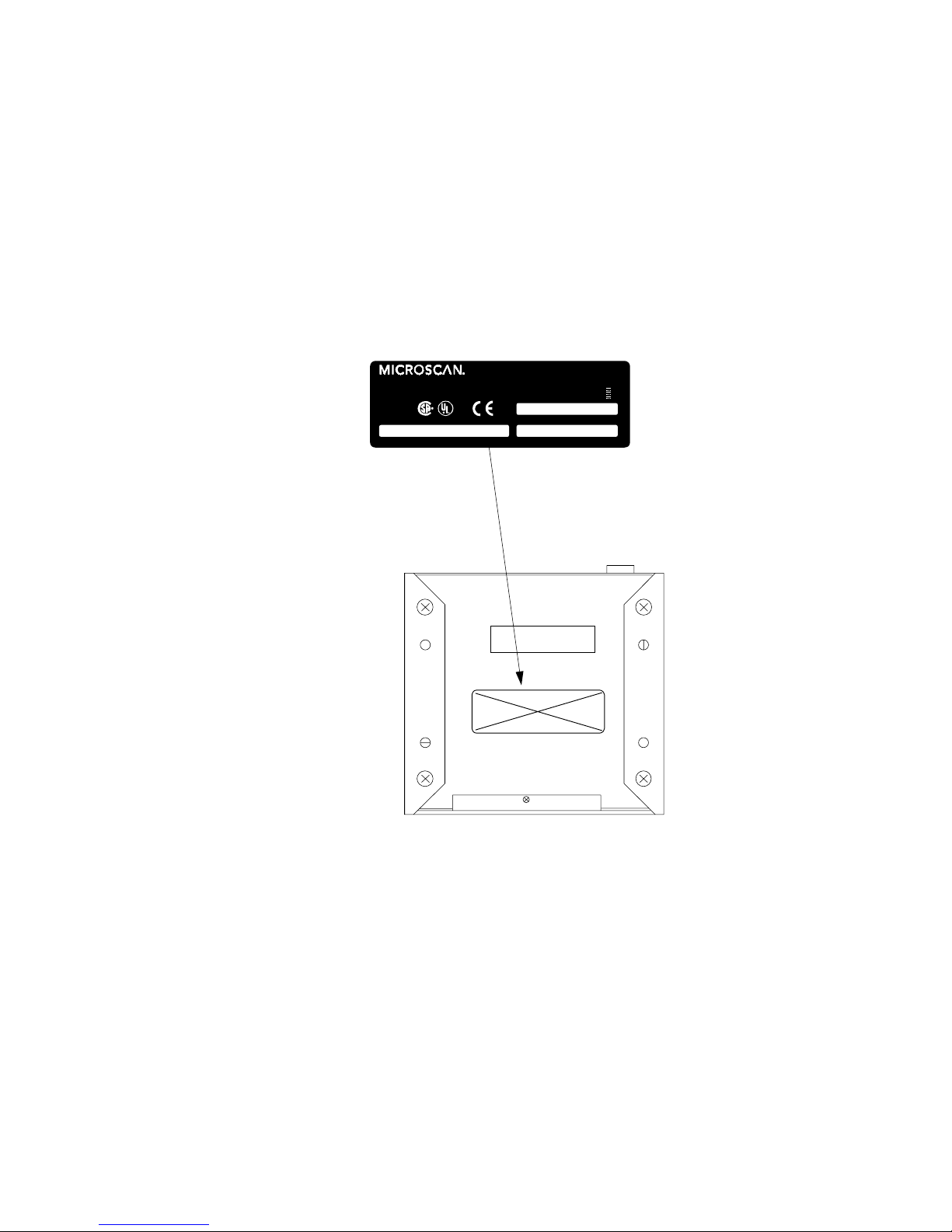
Safety Labels
The following labels are found on the bottom of the MS-3000:
THIS EQUIPMENT HAS BEEN TESTED WITH CLASS A COMPUTING
DEVICES, AND HAS B E E N FO UND TO COM PL Y WITH PART 15 O F FC C
RULES. SEE INST RUCTION MANUA L . OPERATIO N IN A RES IDE NT IA L ARE A
MAY CAUSE UNA CCEPTABL E INTERFERENC E TO RADIO A ND T V
RECEPTION REQUIRING THE OPERATOR TO TAKE WHATEVER STEPS ARE
NECESSARY T O CO RRE C T T H E I NT E RFERE NCE.
FIS NO. MANUFACTURED
SERIAL NUMBER
11-100018-02
1201 S.W. 7th St. Renton, WA 98 0 55
MADE IN U.S.A.
+12V, 40mA
- 12V, 40mA
+ 5V , 300mA
U.S. PATENT NO.: 4,855,581
LISTED
UL 1950
4K68
POWER:
R
CAUT ION: The 6-32 mou nting screws
should not ex tend m ore than 0.12 in.
(3 mm ) int o th e mountin g hol e s.
Page 13

Chapter
MS-3000 Single Head Decoder User’s Manual
1-1
1–Setup and Inst.
1
Setup and
Installation
Chapter Contents
Step 1 - Plan Scanning System............................................................1-2
Step 2 - Attach Cabling........................................................................1-3
Step 3 - Configure Decoder................................................................1-10
Step 4 - Position Scan Head and Label .............................................1-10
Step 5 - Do Read Rate Test...............................................................1-11
Step 6 - Install Decoder......................................................................1-12
Ground and Shield Considerations ....................................................1-14
This chapter provides step-by-step instructions for setting up and installing the 3000 single head decoder.
Note: Bar code labels should meet minimum ANSI (American National
Standards Institute) standards as specified in ANSI Bar Code Print Quality
Guideline, X3.182-1990.
1
Page 14
Chapter 1 Setup and Installation
1-2
MS-3000 Single Head Decoder User’s Manual
1–Setup and Inst.
1
Plan Scanning System
Before installing the MS-3000 decoder you should sketch out a diagram of
your scanning system, showing equipment, connector and cable types, and
cable lengths.
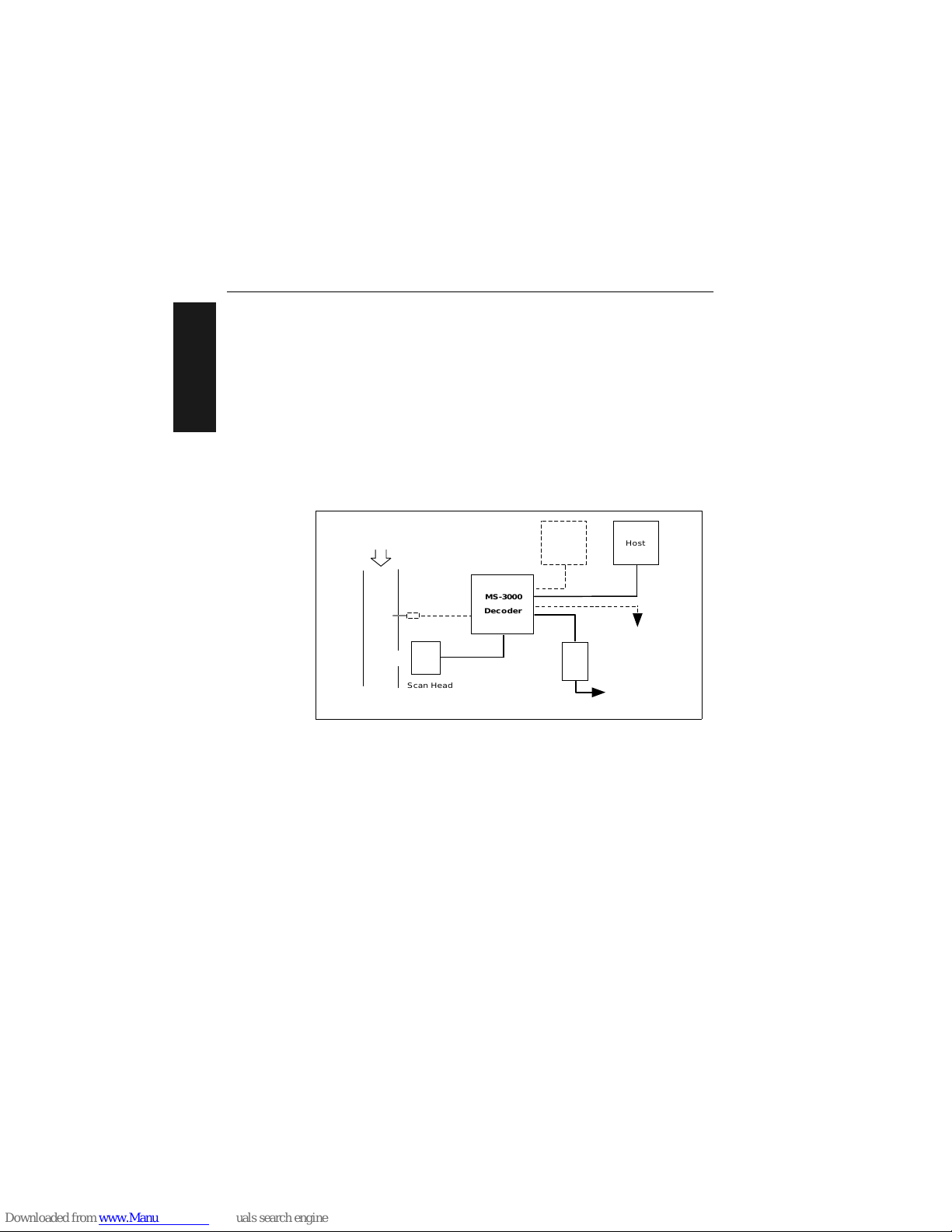
Figure 1-1 shows a possible scanning system setup. There are six I/O con-
nectors on the MS-3000 decoder: the 25-pin host connector (see figure 1-9
on page 1-9), a 6--pin trigger connector (see figure 1-4 on page 1-5), the
5-pin power connector (see figure 1-7 on page 1-6), the modular RJ-45
scan head connector (see figure 1-5 on page 1-5), the modular RJ-11 LAN
connector (see figure 1-8 on page 1-7), and the 9-pin monitor connector
(see figure 1-11 on page 1-9).
Figure 1-1 System Diagram
Object
Detector
8-pin cable
Optional
monitor
To op tiona l multidro p
concentrator
Power
pack
To 120/240 VAC
power supply
Bar-coded
item fl o w
MS-3000
Decoder
Host
Scan Head
Page 15
Attach Cabling
MS-3000 Single Head Decoder User’s Manual
1-3
1–Setup and Inst.
2
Attach Cabling
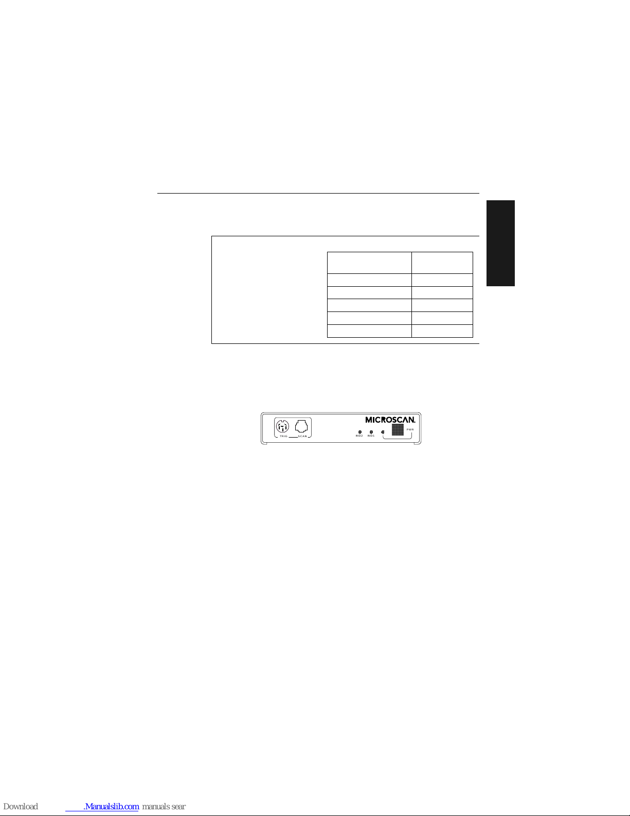
Front Panel Connectors
The MS-3000 decoder has six I/O connectors. On the front panel
(figure 1-2) there are the following two connectors:
a. Trigger (Micr oscan or other object detector) (6-pin DIN socket)
b. Scan head (modular RJ-45)
Figure 1-2 Front Panel
Under ideal conditions, maximum cable lengths can match
the distances shown in table
1-1
. However, since cable
lengths and sizes are dictat ed
by local conditions such as
wire size, wire shape (flat or
round), shielding, grounding,
extraneous signal noise, etc.,
maximum cable distanc es will
vary.
Table 1-1 Cable Distances
Cabling
Maximum
Distance
RS-232 Decoder to Host 50 ft. (15.2 m)
RS-422 Decoder to Host 4000 ft. (1219 m)
Decoder to Scan Head 15 ft. (4.57 m)
RS-485 Multidrop Trunk 4000 ft. (1219 m)
RS-485 Multidrop Drop 10 ft. (3 m)
IND2 IND1
PWR
TRIG SCAN
Page 16

Chapter 1 Setup and Installation
1-4
MS-3000 Single Head Decoder User’s Manual
1–Setup and Inst.
Trigger Connector
The trigger connector (TRIG) is a 6-pin DIN socket (figure 1-3) that mates
with a 240 degree 6-pin DIN plug. Pin assignments are shown in table 1-2.
Pin 1 is the input from the object detector. When operating the decoder in
external trigger mode, a toggle at this pin causes the decoder to begin a
read cycle.
Pin 2 of the trigger connector is a programmable relay driver. The MS-3000
software can be programmed to set this pin high or low upon a good read, a
no read, a good match, or a mismatch. This pin can source or sink 4 mA
(maximum) and can be used to drive a small relay to operate an alarm,
diverter, etc.
Microscan offers an optical object detector (P/N 99-440001-03) that plugs
directly into this connector and a user-customized trigger port connector (P/
N 20-600090-02).
1
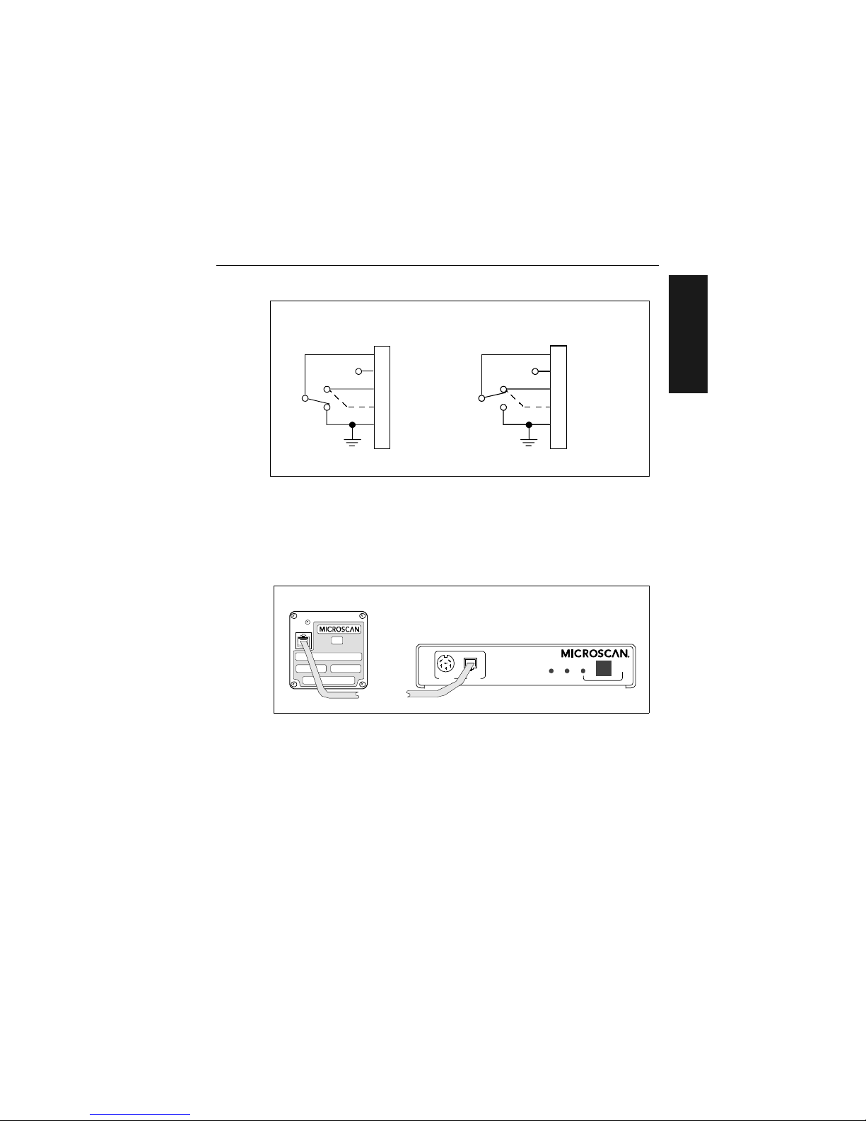
Figure 1-4 shows examples of positive and negative external trigger inputs
that could be applied to the trigger connector. (Shown in untriggered state.)
Table 1-2 Trigger Connector
Pin Assignments
Pin Function
1
Trigger Input +3 VDC
to + 24 VDC
2
TTL Relay driver output
signal 5 VDC
3+5 VDC
4 +12 VDC
5 Ground
6 Not used
1. Trigger sources other than the Microscan object detector can be used. Mechanical switches,
relays, etc.—which tend to be slow and bouncy and produce multiple trigger signals—are not
recommended unless equipped with optical sensors or filtered transitions (optical, Hall effect,
or DC solid state relays).
Figure 1-3 Trigger
Connector Socket
TRIG
5
1
6
32
4
Page 17
Attach Cabling
MS-3000 Single Head Decoder User’s Manual
1-5
1–Setup and Inst.
Figure 1-4 Trigger Connector Wiring Diagram (untriggered)
Scan Head Connector
To prevent voltage loss, cables between decoder and scan head should not
exceed 15 feet (4.57 m) unless wire sizes exceed the minimum 26 AWG.
Figure 1-5 shows a MS-3000 decoder connected to a Microscan MS-500
scan head.
Figure 1-5 Decoder to Scan Head
1
3
4
2
Trigger input
+5 VDC
+12 VDC
Ground
+0 VDC to +24 VDC
5
6
N.C.
Not used
Aux. relay driver
J2
Decoder
Solid
state
switchin g
device
Negative Trigger
1
3
4
2
Trigger input
+5 VDC
+12 VDC
Ground
Not used
Aux. relay driver
+0 VDC to +24 VDC
5
6
N.O.
Solid
state
switchin g
device
J2
Decoder
Positive Trigger
IND2 IND1
PWR
TRIG SCAN
MS-3000 Decoder
MS-520 Scan Head
Page 18
Chapter 1 Setup and Installation
1-6
MS-3000 Single Head Decoder User’s Manual
1–Setup and Inst.
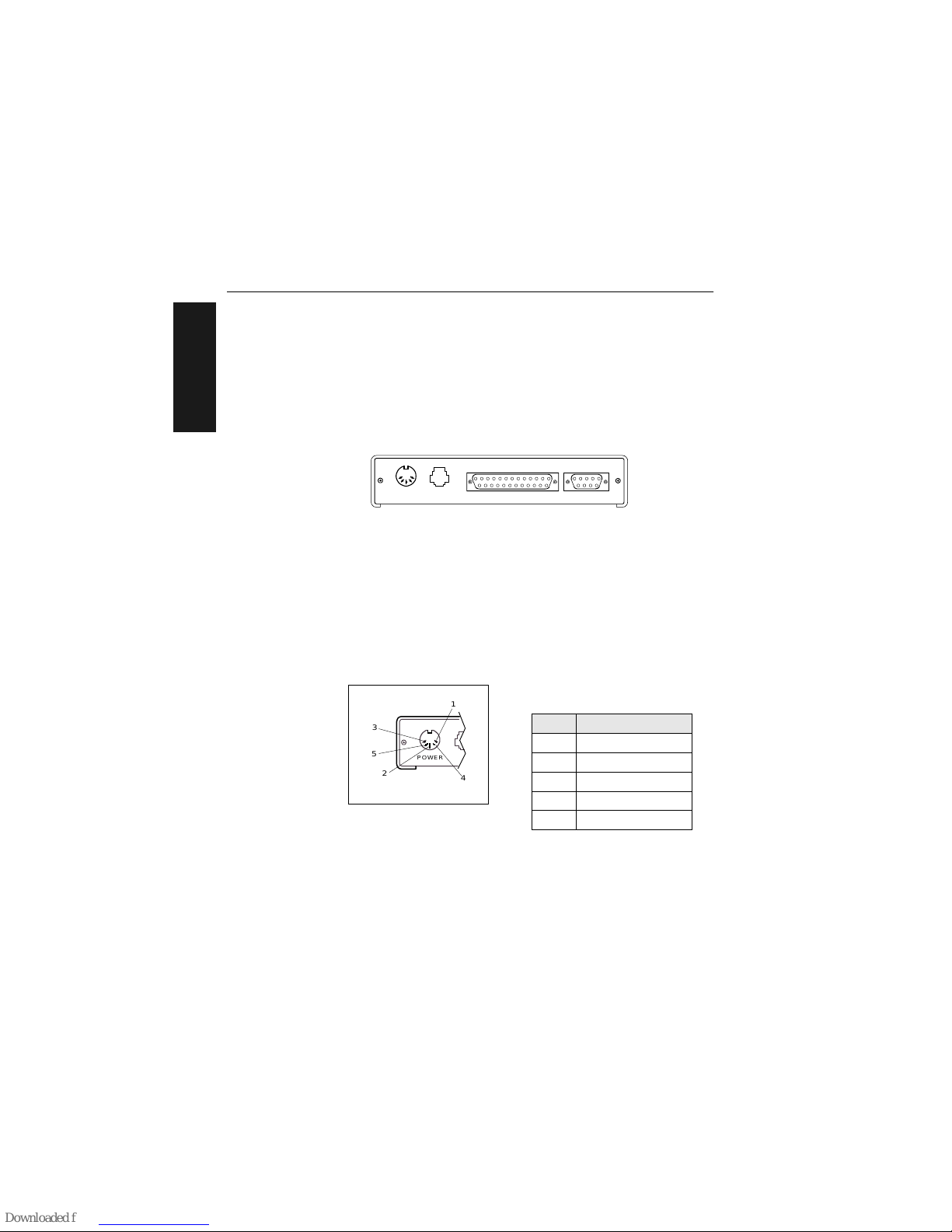
Back Panel Connectors
On the rear panel (figure 1-6) there are the following four connectors:
a. Power (5-pin DIN socket)
b. LAN (modular RJ-11)
c. Host (25-pin D-subminiature socket)
d. Monitor (9-pin D-subminiature socket)
Figure 1-6 Rear Panel of MS-3000 Decoder
Power Connector
The power connector (figure 1-7) has a 5-pin DIN socket with pin assignments shown in table 1-3.
You may also supply the required DC voltages yourself. A mating connector
(Switchcraft #05BL5M plug) is required.
Caution: Switching power supplies for Microscan equipment with a switching
noise of 20 mV or greater with ±12 VDC are not recommended due to excessive ripple characteristics.
Table 1-3 Power Connector
Pin Assignments
Pin Function
1 DC Ground
2Chassis Ground
3 +5 VDC
4 –12 VDC
5 +12 VDC
POWER LAN
HOST MONITOR
Figure 1-7 Power
Connector Socket
POWER
5
1
3
2
4
Page 19

Attach Cabling
MS-3000 Single Head Decoder User’s Manual
1-7
1–Setup and Inst.
LAN Connector
The Local Area Network ( LA N) co nnector allows the MS-300 0 de co de r to
communicate with a mu lt idr op conc en tr ato r via a 4-w ire cabl e (p r efer a bl y
shielded) with a 6 -pin, 6-wir e, RJ- 11 type c onnec tor. Pin ass ignme nts a re as
shown in table 1-4. The LAN connector is used when a MS-3000 decoder is
configured for RS-485 multidrop communications.
For proper operation of RS-485 multidrop communications, the main cable
should not exceed 4000 feet, with each drop no more than 10 feet. The
Microscan MS-5000 multidrop concentrator can support up to 50 decoders
or other multidrop devices on one RS-485 line. Note that the last device
must be terminated correctly. RS-485 pinouts are also available at the host
connector.
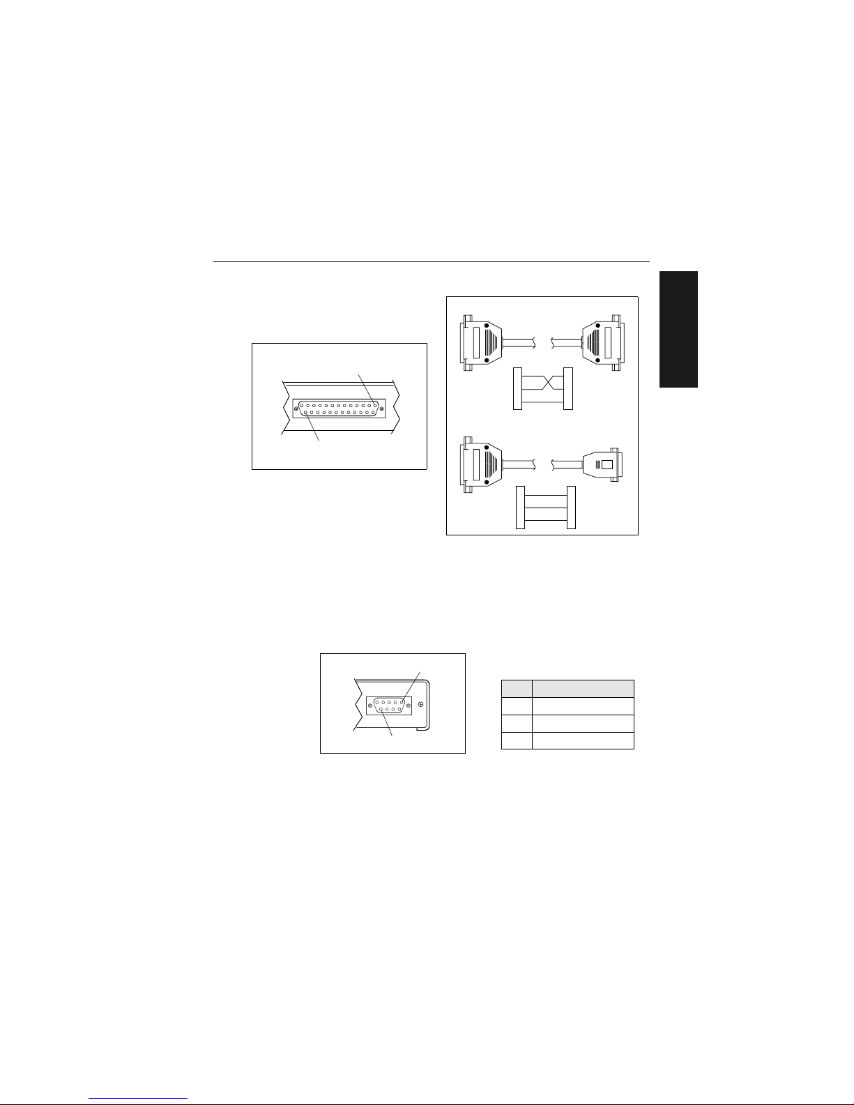
Host Connector
The host connector (figure 1-9 on page 1-9), a 25-pin D-subminiature
socket, allows the decoder to be connected to a host, a concentrator, or
other communications device such as a PLC (programmable logic controller), a monitor, a PC, a relay, a diverter, an alarm, etc.
Note:
All Microscan products are configured as DTE at the host connector
when in RS-232 operation.
Caution: Do not use a host cable with more wires connected than are required
for the application. The host connector of the decoder has many outputs that
could cause damage or interfere with normal operation if connected and improperly used.
Tab le 1-4 LAN Connecto r
Pin Assignments
Pin Function
1 Ground
2 Receive Data (+)
3 Receive Data (–)
4 Transmit Data (+)
5 Transmit Data (–)
Figure 1-8 LAN Connector
16
Page 20

Chapter 1 Setup and Installation
1-8
MS-3000 Single Head Decoder User’s Manual
1–Setup and Inst.
A good read will cause a 5V signal (high or low) to be output to pin 6. A
noread will cause a 5V signal (high or low) to be output to pin 8.
Caution: There must be ±12V present before the decoder will transmit data to
the host. However, the decoder can receive commands without the presence
of either voltage.
Table 1-5 Host Connector Pin Assignmentsa
a. The default communications mode does not support pin 4 (RTS). If RTS is not required by
the host port, pin 4 should not be wired as the results will be unpredictable.
Pin Function Comment
1
Chassis ground connected to dc ground
2
Transmit data +12v data output from the decoder
3
Receive data
±12v signal indicating data from the host to the
decoder
4
Request-to-send
±12v signal asserted high by the decoder when it
has data to send to the host
5
Clear-to-send
±12v signal asserted low by the host to stop the
decoder from sending data to it (data transmission
will resume when the signal is asserted high.)
6
TTL 5V signal indicates a good read
7
Signal Ground connected to chassis ground
8
TTL 5V signal indicates a noread
9
+5 VDC auxiliary supply
10
Trigger input +0 VDC to +24 VDC
11
Default (reset)
resets decoder to default
configuration
12
Aux Input (future use)
13
RXD + RS-422/485
14
TXD – RS-422/485
16
RXD – RS-422/485
19
TXD + RS-422/485
20 +12 VDC
data terminal ready (asserted high on power-up to
indicate decoder is on)
21
Profile Card Input
22
Signal Ground
23
–12 VDC
24
+12 VDC
25
Match Code next label read as master label, if enabled
Page 21
Attach Cabling
MS-3000 Single Head Decoder User’s Manual
1-9
1–Setup and Inst.
Figure 1-10 DTE and DCE Host
Connections
Monitor Connector
The monitor connector (auxiliary terminal) connects the decoder to an auxiliary monitor via a 9-pin D-subminiature socket and cable. Table 1-6 shows
auxiliary terminal pin assignments. Communication at this connector is
RS-232 only.
Figure 1-11 Monitor Connector
Figure 1-9 Host Connector
HOST
1
25
Transmit
2
3
7
2
3
7Signal Grnd
HostDecoder
Receive
Transmit
Signal Grnd
Receive
Transmit
Receive
2
3
7
2
3
5 Signal G rn d
Host
Decoder
Transmit
Receive
Signal Grnd
DB-25 DTE to DE-9 DCE Connection
DB-25 DTE to DB-25 DTE Connection
Table 1-6 Monitor Connector
Pin Assignment s
Pin Function
2 Receive Data (in)
3 Transmit Data (out)
5 Signal Ground
MONITOR
1
9
Page 22

Chapter 1 Setup and Installation
1-10
MS-3000 Single Head Decoder User’s Manual
1–Setup and Inst.
3
Configure Decoder
Settings for Communications, Operations, Code Types, and User Outputs
and Raster Setup are stored in non-volatile memory and can be configured
by menu, serial command, or profile card commands.
For explanations of configuration settings, see Chapter 2, “Menu Configu-
ration.”
To establish communications you will need to match the host’s or auxiliary
terminal’s communication settings with your decoder’s settings (see Com-
munications Menu” on page 2-5). Also make certain that the code type
enabled in the decoder matches that of the label being used (see Code
Types Menu” on page 2-22).
Hint: Sending the <P> command will allow your scan head to read all of the
listed code types.
4
Position Scan Head and Label
Before testing, you will need to position the scan head and label in a manner that matches as nearly as possible the actual conditions of your application. Consult your scan head user’s manual for important setup
specifications.
Communicating with an d ASCII Terminal
The MS-3000 decoder communicates in full duplex, terminal mode with no
handshake. It also recognizes carriage returns and line feeds.
The host or ASCII terminal must match the following de fault settin gs before an y
communication can ta ke plac e:
9600
Baud Rate,
Seven
Data Bits,
Even
Parity,
and
One
Stop Bit.
A PC or Macintosh computer can be used as a dumb terminal if connected as
shown in table 1-5 on page 1-8 and running a communications program set to
the above defaults. See your computer user’s manual for communication’s port
pinouts.
Page 23

Do Read Rate Test
MS-3000 Single Head Decoder User’s Manual
1-11
1–Setup and Inst.
5
Do Read Rate Test
This test calculates the percentage of scans decoded. It is useful during
setup procedures to help optimize scan head-to-label orientation.
a. Place the label used i n your application i n front of the scan hea d and
within the desired read range.
Note:
Ensure that the label being scanned is of a code type enabled in the
decoder’s software.
Hint:
Read rates are easier to read on the screen if Postamble is enabled.
b. Select from the ESP Utilities menu or send a <C> command to the
decoder to start testing (see the “Enter Read Rate Test” command on
page 5-5).
A percentage number from 0 to 100
will be displayed on the monitor in
the read rate test indicating the ratio
of good reads per total number of
scans.
c. Find the correct read rate area by
moving the label in and out and right
and left while observing read rate on
the monitor.
Avoid the specular reflection area (see scan head user’s manual).
d. Record the range area measurements and file the test results for
future reference.
If the results are not satisfactory, reposition or re-configure the
decoder or choose a different narrow-bar-width label size.
e. Select from the ESP Utilities menu or send a <J> command to the
decoder when testing is complete (see the “Exit Read Rate Test” command on page 5-5).
Read Rate
Percentage
Label Data
Page 24
Chapter 1 Setup and Installation
1-12
MS-3000 Single Head Decoder User’s Manual
1–Setup and Inst.
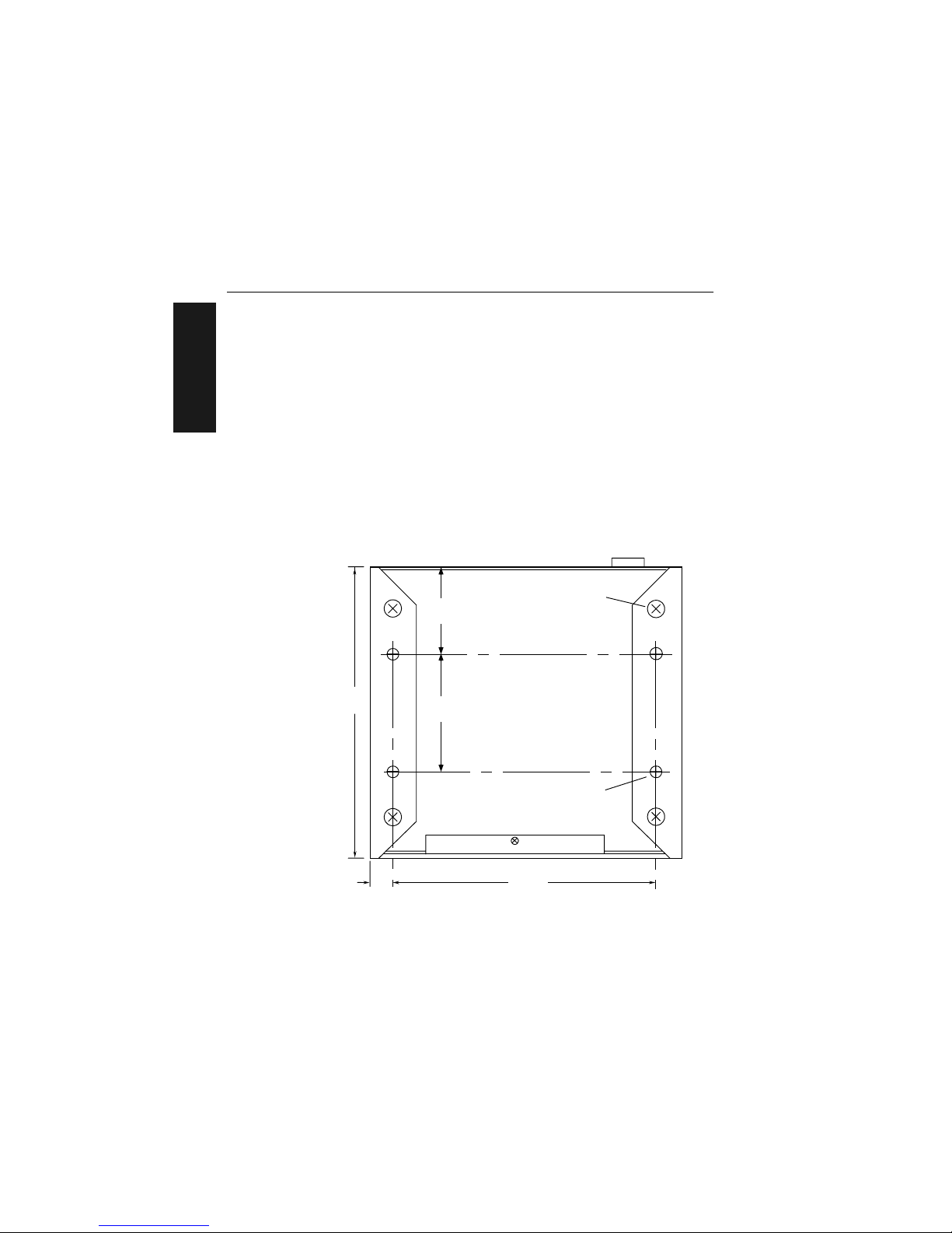
6
Install Decoder
The MS-3000 decoder can be mounted temporarily using the four rubber
pads, or permanently, as follows:
a. Position the decoder in a dry place.
b. Before mounting, ensure that there is at least a 3 inch (76.2 mm) clear-
ance at the rear and front of the decoder for the connectors and cables
being used.
c. Use the measurements provided in figure 1-12 to locate centers of
mounting holes and drill four 5/32 inch or four 4 mm holes.
d. Secure decoder with four 6-32 screws of the appropriate length.
Caution: Make certain that mounting screws do not penetrate into the
decoder case more than .175 in. (4.4 mm) or damage to the decoder could
result.
Figure 1-12 Bottom Mounting Diagram (not full size)
6.2"
(157.48)
Measurements in inche s (m illim ete rs )
Front
0.5"
(12.7)
1.85"
(46.99)
2.5"
(63.5)
5.6"
(142.24)
6/32 threads
(4 plac es )
Optional foot pads
(4 places)
Page 25
Install Decoder
MS-3000 Single Head Decoder User’s Manual
1-13
1–Setup and Inst.
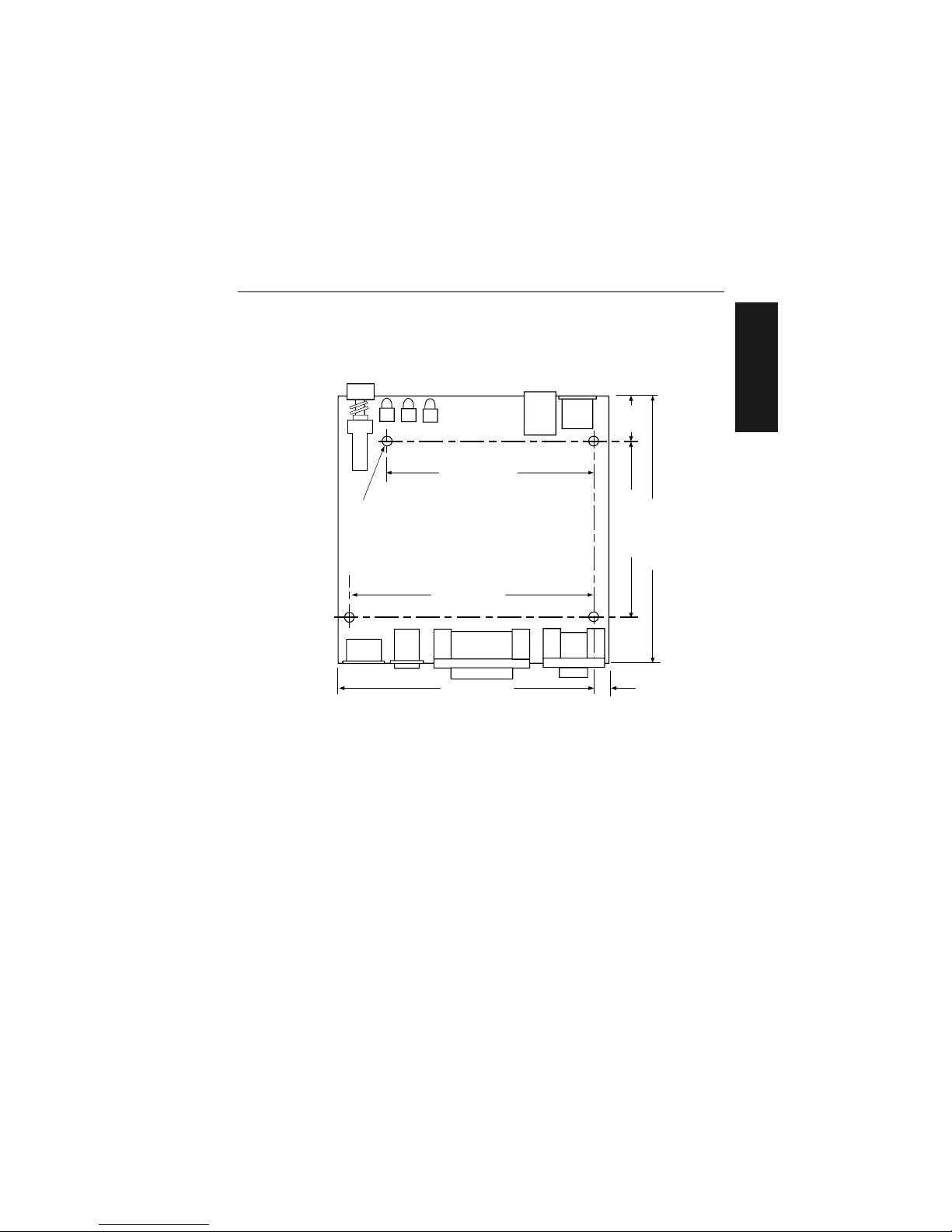
If the unit does not have housing, use the measurements provided in
figure 1-13 to locate the centers of the mounting holes.
Figure 1-13 Mounting Diagram (without housing, not full size)
4.5" (114.30)
3.8" (96.52)
5.8" (147.32)
5.2" (132.08)
0.030" (7.62)
5.8" (147.32)
0.160" (4.06)
Dia. (4 places)
Front
1.0"
(25.4)
Measurements in inc hes (millimet ers)
Page 26

Chapter 1 Setup and Installation
1-14
MS-3000 Single Head Decoder User’s Manual
1–Setup and Inst.
Ground and Shield Considerations
Proper grounding is necessary for operator safety, noise reduction, and the
protection of equipment from voltage transients. Buildings–including any
steelwork, all circuits, and all junction boxes–must be grounded directly to
an earth ground in compliance with local and national electrical codes.
RS-232 signals have a common signal ground (pin 7 of the 25-pin connector). Pin 7 is normally connected to pin 1 (chassis ground) in the decoder;
however, under certain conditions (e.g., when potential differences exist
between power outlet grounds) signal and chassis grounds can be isolated
from each other inside the decoder by Microscan technicians.
Any data line, as necessary, can be shielded. If shielding is used, isolate it
from the decoder and ground only to the host earth ground.
Noise Interference
Noise interference can be mini-
mized if cabling subject to
noise interference is twisted
and/or shielded or encased in
grounded conduit, and the
conduit or shielding (“drain”
line) is grounded only to earth
ground at the host, as shown in
figure 1-14. You might need to
examine and if necessa ry cut
the shielding connec ti on at or
near the concentrator cable
connector.
Ground Loops
Ground loops, signal degradation due to different ground potentials in com-
municating devices, can be eliminated or minimized by ensuring that the
host, concentrator, and their power supplies are connected to a common
earth ground.
Figure 1-14 Grounding Diagram, Decoder-Host
HOST
Decoder
Shieldin g
Communication s
Cable
Earth Ground
Page 27

Chapter
MS-3000 Single Head Decoder User’s Manual
2-1
2–Menu Config.
Menu
Configuration
Chapter Contents
Communications Menu........................................................................2-5
Operations Menu...............................................................................2-13
Code Types Menu..............................................................................2-22
User Outputs Menu............................................................................2-29
Raster Setup Menu............................................................................2-33
This chapter describes how to configure the MS-3000 decoder with on
screen menu commands from a host or auxiliary terminal.
All keystrokes are in bold typeface.
Default parameters in the menu structures are also in bold typeface.
All of these parameters, with the exception of Full Screens, can also be
changed by serial commands (see Chapter 3, “Serial Configuration”).
In addition, most of these configuration parameters can also be changed
with a Microscan profile card (P/N 99-500011-01), obtainable from your
Microscan representative (see Chapter 4, “Profile Card Configuration”).
Communicating with an ASCII Terminal
The MS-3000 decoder communicates in full duplex, terminal mode with no
handshake. It also recognizes carriage returns and line feeds.
The host or ASCII terminal with must match the following default settings
before any communication can take place: 9600 Baud Rate, Seven Data
Bits
, Even
Parity, and
One
Stop Bit.
2
Page 28
Chapter 2 Menu Configuration
2-2
MS-3000 Single Head Decoder User’s Manual
2–Menu Config.
Entering the Menu Configuration Program
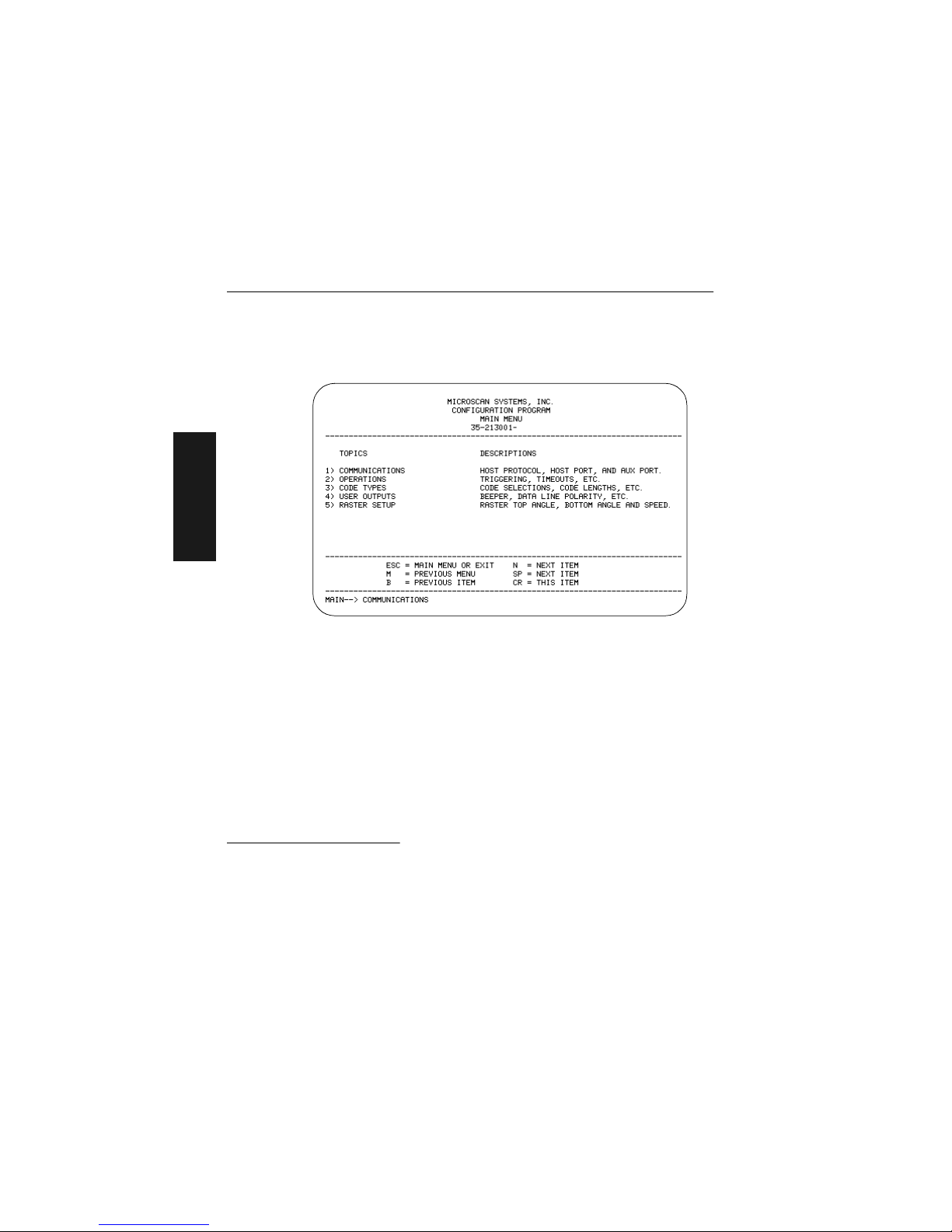
To see the Main menu (figure 2-1), from an ASCII terminal that is connected to the decoder, send the serial command <D> (enter the < >
brackets as well as the upper case D).
1
Figure 2-1 Configuration Program - Main Menu
2
If the menu does not appear, see Appendix D, “Troubleshooting,” on
page A-6.
Using the Menu Configuration Program
The bottom line on the screen is called the command line. The command
line identif ies your place in the menu program, shows current status and
allows you to review and change options. Use the designated keys
3
to
scroll to and select the parameter you wish to change; press SP (space
bar key) or N to scroll ahead, B to scroll back, CR (carriage return key) to
select, and M to return to the previous higher level menu. To return to the
Main menu at any time, press ESC (escape key) and M.
1. Command start character by defa ult is a left angl e bracket, <. It ma y be redefine d by
menu or serial command. However, the end character, a right angle bracket, >, cannot be changed.
2. Item 5, Raster Setup, applies only to the MS-1280 raster scan head.
3. The menu navigational keys are displayed in each menu.
xx
Page 29
MS-3000 Single Head Decoder User’s Manual
2-3
2–Menu Config.
For example, to enable LRC (see figure 2-2, “Communications Menu
Structure,” on page 2-5 and “Longitudinal Redundancy Check” on
page 2-10), you would use the following command line path:
To view LRC’s new status in the menu , p ress M to refresh the screen. To
return to the Main menu, press M again. You can make additional c ha nges
within another menu before exiting the program. Simply follow the same
method of scrolling to and selecting each main topic, then its subtopics, until
you reach the par a me te r y ou wa nt to cha ng e. Re me mb er , to ret u r n to th e
Main menu at any time, press ESC (escape key) and M.
Some parameters are user defined, in which case they prompt you with an
arrow for data, such as:
At the prompt, redefine the parameter within the allowable range, and press
CR to enable.
Main —> Communications
Main —> Operations
Main —> Code Types
Main —> User Outputs
Main —> Raster Setup
Communications —> Host Protocol
Communications —> Host Por t
Communications —> Aux P ort
Host Protocol —> Protocol
Host Protocol —> Preamble = ^M
Host Protocol —> Preamble = Disabled
Host Protocol —> Postamble = ^M^J
Host Protocol —> Postamble = Disab le d
Host Protocol —> LRC = Disabled
Host Protocol —> Response Timeout
in 1ms incs = 12
Host Protocol —> Intercharacter Delay
in 1ms incs = 0
Host Protocol —> LRC = Disabled
Host Protocol —> LRC = Enabled
From the Main menu, press
CR at the Communications
prompt (this is the first prompt
displayed in the Menu Configuration Program) to access the
Communications menu.
Since LRC is a subtopic of
Host Protocol, press CR to
access the Host Protocol
parameters.
Protocol is the first parameter
under Host Protocol. Press SP
until you reach LRC, then
press CR.
To enable LRC, pr es s CR, SP,
and CR.
Page 30

Chapter 2 Menu Configuration
2-4
MS-3000 Single Head Decoder User’s Manual
2–Menu Config.
Saving Menu Changes
Press ESC (escape key) to see the following on the command line:
Press M to return to the Main menu, or press E to exit the Menu Configuration program. If E is pressed, the following question will appear:
Press N to exit without saving changes, or press Y to retain the current settings to non-volatile RAM for power up. If Y is selected, a beep will indicate
the save has been carried out.
Loss of Communications
Defaulting might be necessary if communications between the decoder and
another device are interrupted or if using incompatible equipment (for
example, a terminal is set to communicate at 9600 baud, but the decoder is
configured at 38.4K baud). Communication can also be lost if an address
has been assigned to the decoder.
To reset parameters to default values, see Appendix C, “Defaulting the
Decoder,” on page A-4.
Defining Special Characters
To define any control character from the ASCII table: Press SP once, then
enter the control character by holding down the control key and simultaneously pressing the desired character. For example to define a line feed,
press SP, then Control and J simultaneously. It is displayed as ^J on the
command line and as <LF> in the menu when the screen is refreshed.
To define CR as a character: Press SP, then CR. It is displayed as ^M on
the command line and as <CR> in the menu when the screen is refreshed.
To define a space as a character: Press SP twice. It is displayed as a blank
space in the menu when the screen is refreshed. While it appears that nothing has been assigned, the hex value 20 will be sent during data transmission.
To select NUL as t he char act er: Press SP, then a 0 (zero). It is displayed as
<NUL> in the menu when the screen is refreshed.
Page 31

Communications Menu
MS-3000 Single Head Decoder User’s Manual
2-5
2–Menu Config.
Communications Menu
The Communications menu allows you to set the communication protocols
between the decoder and the host.
Figure 2-2 Communications Menu Structure
Protocol
–
Point-to-Point
–
Point-to-Point
w/RTS/CTS
–
Point-to-Point
w/XON/XOFF
–
Point-to-Point
w/RTS/CTS &
XON/XOFF
–
Polling Mode D
–
Multidrop
–
Address = 1
– User Definable (1 to 50)
–
User Defined
–
RES – Address = ^A – REQ – EOT – STX – ETX – ACK – NAK
–
User Defined Multidrop
–
RES – Address = ^A – REQ – EOT – STX – ETX – ACK – NAK
Preamble
–
^M
–
User
Definable
(ASCII char.)
Preamble
–
Disabled
–
Enabled
Postamble
–
^M ^J
–
User
Definable
(ASCII char.)
Postamble
–
Disabled
–
Enabled
Host Protocol
LRC
–
Disabled
–
Enabled
Response Timeout
–
12
–
User Definable (0 to 65,000)
Interchar Delay
–
0
–
User Definable (0 to 255)
Baud Rate
–
9600– 1200
–
19.2K– 2400
–
38.4K– 4800
–
600
Parity
–
Even
–
Odd
–
None
Stop Bits
–
One
–
Two
Data Bits
–
Seven
–
Eight
Communications
Host Port
Aux Port
Baud Rate
–
9600– 1200
–
19.2K– 2400
–
38.4K– 4800
–
600
Parity
–
Even
–
Odd
–
None
Stop Bits
–
One
–
Two
Data Bits
–
Seven
–
Eight
–
Bold text represents default settings.
RS-422
–
Disabled
–
Enabled
Aux Mode
–
Disabled
–
Transparent
–
Half Duplex
–
Full Duplex
Page 32

Chapter 2 Menu Configuration
2-6
MS-3000 Single Head Decoder User’s Manual
2–Menu Config.
There are three subtopics in this m enu: Hos t Protocol, H ost Port, and Aux Po rt.
To help visualize the menu’s organization and to locat e the page numb er
where each topic is describ ed, se e figure 2-2, “Communications Menu
Structure,” on page 2-5.
Note: Changes in Communications parameters or assigning an addres s to the
decoder can cause loss of communica tio ns wit h the co nfi guration termi nal when
you exit the menu program (whether or not changes are saved for power-on).
Host Protocol Parameters
Protocol
Default: Point-to-Point
Options: Point-to-Point, Point-to-Point with RTS and CTS, Point-to-Point
with XON/XOFF, Point-to-Point with RTS/CTS and XON/XOFF,
Polling Mode D, Multidrop, User Defined, User Defined Multidrop
Protocols define the seq ue nce an d for m at i n whi ch in fo rm at io n is t ran sf erre d
between devices. Generally there are two basic protocol modes: unpolled
and polled. In unpolled mode (all of the Point-to-Point protocols), a device
sends information wi th ou t bei ng asked f or b y the ho st . I n polled mode (Multidrop, Polling Mode D, an d Us er D efi n ed Mul ti dr op), a device has an address
and waits for a request from the host before sending data.
Note: User Defined and User Defined Multidrop have more options available to
them. Selection instructions for these protocols are provided under each topic.
Selecting: Has this effect:
Point-to-Point
Has no address and sends data to the host
(RS-232) whenever it is available and without any
request or handshake from the host.
Point-to-Point with
RTS/CTS (Request-toSend/Clear-to-Send)
Used only with RS-232. This is a simple handshaking
protocol that allows a device to initiate data transfers
to the host with an RTS (request-to-send)
transmission. The host, when ready, responds with a
CTS (clear-to-send) and the data is transmitted. RTS
and CTS signals are transmitted over two dedicated
wires (pins 4 and 5) as defined in the RS-232
standard.
Page 33

Communications Menu
MS-3000 Single Head Decoder User’s Manual
2-7
2–Menu Config.
Point-to-Point
with XON/XOFF
(Transmitter On/Off)
Used only with RS-232
or RS-422. This selection
enables the host to send a single byte
transmission command of start (XON) or stop
(XOFF). If an XOFF has been received from the
host, data will not be sent to the host until the
host sends an XON. During the XOFF phase, the
host is free to carry on other chores and accept
data from other devices.
Point-to-Point
with RTS/CTS
and XON/XOFF
Used only with RS-232. It is a combination of Pointto-Point with RTS/CTS and Point-to-Point with
XON/XOFF.
Polling Mode D Like Point-to-Point, Polling Mode D requires a
separate connection to the host but unlike Point-toPoint, it requires the device to have an address and
to wait for a poll from the host before sending data.
When in Polling Mode D, an address 1 is
automatically displayed on the configuration
screen. However, during transmission, a 1C hex
poll address (FS) and a 1D hex select address
(GS) are substituted for the 1.
Multidropa
Similar to Polling Mode D except that a unique poll
address and select address are required for each
multidrop device, and only one host port connection
is needed for up to 50 devices. (For Multidrop poll
and select characters, see Table A-6, “Multidrop
Address Characters,” on page A-20.)
Requires a concentrator or controller using RS-485
communications. When Multidrop is selected, the
protocol characters for RES, REQ, etc. are
assigned automatically. (See “Appendix I —
Multidrop Communications” on page A-17 for
poll and select sequences.)
Selecting: Has this effect:
Note: Decoders intended to link up to a
MS-5000 multidrop
concentrator can
only be configured in
standard Multidrop
protocol.
Hint: Attach a tag to
each decoder to
identify its multidrop
address.
Page 34

Chapter 2 Menu Configuration
2-8
MS-3000 Single Head Decoder User’s Manual
2–Menu Config.
Note: Definitions of commands in User Defined and User Defined Multidrop
must be duplicated in host applications to enable poll and select sequences to
execute correctly during transmission.
Typically, parameters in User Defined Multidrop are defined by first
enabling Multidrop, then enabling User Defined Multidrop. This pre-loads
Multidrop characters into the parameters. You then change individual characters to match the host or other requirements.
User Defined
Used only with RS-232 or RS-422. ASCII
characters can be assigned as an address and as
protocol commands (RES, REQ, EOT, STX, ETX,
ACK, and NAK). User Defined is necessary when a
new protocol must be defined to match a specific
host protocol. When User Defined is selected, the
displayed protocol commands match those of the
previously selected protocol. User Defined is
considered to be in a polled mode only if an address
has been assigned. The address can be any ASCII
character from the ASCII in appendix B, except
NUL.
b
User Defined
Multidrop
Used when connecting to a concentrator or other
device that does not match standard Multidrop
protocol.
Any single character (01 hex to 7E hex) in the ASCII
table can be assigned as the address character.
The character chosen is used as the poll character
and the subsequent ASCII character becomes the
select character. For example, if a ^A (01 hex) is
selected as the address, ^B (02 hex) becomes the
select address that the host will use in sending host
select commands. (See Table A-I, “Multidrop
Communications,” on page A-17.)
a. Once the decoder is configured for Multidrop, a profile card, a terminal connected to the aux-
iliary RS-232 pins, or a default procedure must be used to access the configuration menus
again (although serial commands will continue to function).
b. For example a simple ACK/NAK protocol can be developed by first selecting Point-to-Point,
then User Defined, and then assigning characters to ACK and NAK commands. First scroll to
the following command:
HOST PROTOCOL --> PROTOCOL --> USER DEFINED--> ACK = -->
Enter a ^F by holding down the Control
key while pressing the F key, and then press CR to
see the following:
HOST PROTOCOL --> PROTOCOL --> USER DEFINED --> ACK = ^F
The mnemonics ACK and NAK replace the default NULs in the menu.
Selecting: Has this effect:
NOTE: A specific
ASCII character must
not be assigned more
than once.
Note: A specific ASCII
character must not be
assigned more than
once.
Note: A specific
ASCII character
must not be assigned more than
once.
Page 35

Communications Menu
MS-3000 Single Head Decoder User’s Manual
2-9
2–Menu Config.
Preamble
Default: ^M (and a null). Corresponds to <CR><NUL> (carriage return/null)
displayed in the menu.
Options: Any ASCII character, including control characters. Control char-
acters entered on the command line are displayed in the menu as
mnemonic characters. See “Defining Special Characters,” on
page 2-4 and table A-2 on page A-3.
Allows you to define a one or two character data string that can be added to
the front of the decoded data. For example, a carriage return and line feed
would display each decoded message on its own line.
If User Defined, Polling Mode D, or Multidrop is enabled, the Preamble and
Postamble character s a re t ran smi tt e d wi th in th e STX a nd ETX da ta blo ck.
Preamble (enable/disable)
Default: Disabled
Options: Disabled, Enabled (within any protocol)
Allows you to enable or disable the preamble character(s).
Postamble
Default: ^M^J. Corresponds to <CR><LF> (carriage return/line fe ed) dis-
played in the menu.
Options: Any ASCII character, including control characters. Control char-
acters entered on the command line are displayed in the menu as
mnemonic characters. See “Defining Special Characters,” on
page 2-4 and Table A-2, “ASCII Table with Control Characters,” on page A- 3.
Allows you to define a one or two character data string that can be added
after the decoded message.
If User Defined, Polling Mode D, or Multidrop is enabled, the Postamble and
Preamble characters are t ran sm it te d wi thi n th e STX and ETX da t a bl ock.
Postamble (enable/disable)
Default: Disabled
Options: Disabled, Enabled (within any protocol)
Allows you to enable or disable the Postamble character(s).
Page 36

Chapter 2 Menu Configuration
2-10
MS-3000 Single Head Decoder User’s Manual
2–Menu Config.
Longitudinal Redundancy Check
Default: Disabled (in unpolled mode), Enabled (in polled mode)
Options: Disabled, Enabled
An error-checking routine that verifies the accuracy of transmissions. It is
the exclusive OR of all characters following the SOM (start of message) up
to and including the EOM (end of message).
Response Timeout
Default: 12 ms
Options: 0 to 65,000 ms. A zero (0) causes an indefinite wait.
Allows you to set the time the decoder will wait before timing out if ACK,
NAK, and ETX are enabled, and a host response is expected.
Intercharacter Delay
Default: 0. Corresponds to 0 ms displayed in the menu.
Options: 0 to 255. A zero (0) causes no delay between characters.
Allows you to set the time interval in milliseconds between individual characters transmitted from the decoder to the host. A high setting will significantly slow down communications. For example, a 200 setting will result in
a 1/5 second delay between each character that is transmitted.
Host Port Parameters
Allows you to set parameters for host port communications.
Baud Rate
Default: 9600
Options: 9600, 19.2K, 38.4K, 600, 1200, 2400, 4800
Allows you to set the number of bits transmitted per second.
NOTE: Due to timing considerations, polled modes require 2400 baud or faster.
Parity
Default: Even
Options: Even, Odd, None
Allows you to select an error detection routine in which one data bit in each
character is set to 1 or 0 so that the total number of 1 bits in the data field is
even or odd.
Page 37

Communications Menu
MS-3000 Single Head Decoder User’s Manual
2-11
2–Menu Config.
Stop Bits
Default: One
Options: One, Two
Allows you to select the last one or two bits in each character to indicate the
end of the character.
Data Bits
Default: Seven
Options: Seven, Eight
Allows you to establish the total number of bits in each character.
RS-422
Default: Disabled
Options: Disabled, Enabled
Note: Used only in Point-to-Point protocol only, and not with RTS/CTS.
Whenever RS-422 is disabled, RS-232 is enabled in the background.
However, when Multidrop is enabled, the functioning protocol is RS-485
regardless of the displayed status of RS-422 in the menus. Before enabling
RS-422, first double-check that Multidrop is not enabled. (See “Protocol,”
on page 2-6.)
(See App end ix G, “Int er face St and ar ds,” on page A-1 2 for additional
information on RS-422.)
Aux Port Parameters
Aux Port (auxiliary port) allows you to set communications settings between
the decoder and an auxiliary monitor. An auxiliary monitor can be used to
configure the menus, send data to the host, and display data transmissions
originating from the host or decoder.
Note: Aux Port operates in RS-232 only. See Appendix H, “Auxiliary Moni-
tor,” on page A-13 for a full description of auxiliary port options.
Page 38

Chapter 2 Menu Configuration
2-12
MS-3000 Single Head Decoder User’s Manual
2–Menu Config.
Aux Mode
Default: Disabled
Options: Disabled, Transparent, Half Duplex, Full Duplex
Aux Mode (auxiliary mode) allows you to select a co mmunica tio ns mod e f or
auxiliary operations (see Appendix H, “Auxiliary Monitor,” on page
A-13).
Other Aux Port Parameters
The other Aux Port parameters—Baud Rate, Parity, Stop Bits, and Data
Bits—are identical to the host port parameters and are changed in the
same manner (see page 2-10).
Note: The Aux Port baud rate should never exceed Host Port baud rate or
auxiliary port data could be lost.
Page 39

Operations Menu
MS-3000 Single Head Decoder User’s Manual
2-13
2–Menu Config.
Operations Menu
The Operations menu allows you to set the operations parameters for the
decoder.
To help visualize the menu’s organization and to locate the page number
where each topic is described, see figure 2-3.
Figure 2-3 Operations Menu Structure
Triggering Mode
–
Continuous Read
–
Continuous Read 1
Output
–
External Level
–
External Edge
–
Serial Data
–
Serial Data & Edge
End of
Read Cycle
–
Timeout
–
New Trigger
–
Timeout &
New Trigger
Timeout in
10 ms incs *
–
100
–
User Definable
(ASCII char.)
Serial Trigger
Character
–
^]
–
User
Definable
(ASCII char.)
External Trigger
Polarity
–
Positive
–
Negative
Number of
Reads
–
1
–
User
Definable
(1 to 31)
Match Code
–
Disabled
–
Enabled
Bar Code
Output
–
Enabled
–
Disabled
Number of
Labels
–
1
–
User
Definable
(1 to 6)
Operations
–
Bold text represents default settings.
Field
Separator
–
, (comma)
–
User
Definable
(ASCII char.)
* Divide the number entered on the command line by 100 for time in seconds.
Noread Message
(7 digits)
–
NOREAD
–
User Definable
(ASCII char.)
Noread
Message
–
Enabled
–
Disabled
When to
Output
–
As Soon As
Possible
–
End of Read
Cycle
Page 40

Chapter 2 Menu Configuration
2-14
MS-3000 Single Head Decoder User’s Manual
2–Menu Config.
Triggering Mode
Default: Continuous Read
Options: Continuous Read, Continuous Read 1 Output, External Level,
External Edge, Serial Data, Serial Data & External Edge
Allows you to establish the type of trigger event that will initiate or end the
read cycle. (See “End of Read Cycle” on page 2-16.)
Selecting: Has this effect:
Continuous Read T rigger input options are disabled and the decoder is
always in the read cycle. Bar code data is decoded,
and label information is transmitted repeatedly, as
long as the label is in the range of the scan head.
When To Output options have no affect on
Continuous Read. Continuous Read is useful in
testing label or scan head functions.
Continuous Read 1
Output
a
Label data is immediately transmitted with Timeout
enabled for End Of Read Cycle. If the label doesn't
change, the decoder will repeat the output at the end
of each subsequent timeout period. For example, if
Timeout were set to one second, the decoder would
output the label data immediately, and then repeat
the output at intervals of one second, for as long as
the label continued to be scanned.
With Timeout disabled (that is, End Of Read Cycle
set to New Trigger), the decoder will output the
current label data immediately, but output it only
once. A new label appearing at any time in the scan
range will produce a new read output as long as the
new label is not identical to the previous label.
External Level Allows a read cycle to be initiated by a trigger signal
from an object detector when an object appears
within the detector’s range. The read cycle endures
until the object moves out of the detector’s range
(figure -1 on page -15), unless a timeout occurs
and Timeout is enabled for End of Read Cycle (page
2-16).
b
NOTE: If Continuous Read is enabled
with Match Code, the
decoder defaults to
Continuous Read 1
Output mode.
NOTE: Enabling
Continuous Read 1
Output when Number of Labels (page
2-21) is set to any
number greater than
one will cause Number of Labels to default back to one.
Page 41

Operations Menu
MS-3000 Single Head Decoder User’s Manual
2-15
2–Menu Config.
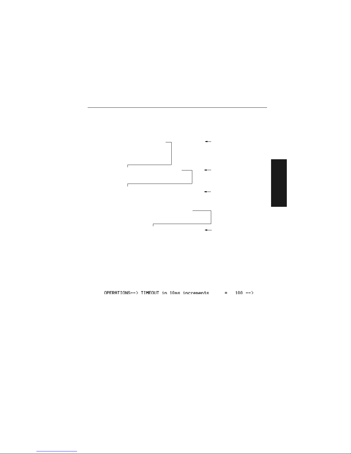
External Edge As with Level, Edge allows a read cycle to be
initiated by a trigger signal from an object detector
when it detects the appearance of an object (rising
edge). But unlike Level mode, the removal of an
object (falling edge) does not end the read cycle.
With Edge enabled, the read cycle ends with a good
read, a timeout, or a new trigger (figure -1).
Serial Data The decoder accepts an ASCII character from the
host or controlling device as a trigger to start a read
cycle.
Serial Data &
External Edge
The decoder accepts either an external trigger or a
serial ASCII command to start a read cycle.
a. Continuous Read 1 Output will allow an output regardless of how Goo d Decode Rea d is se t.
b. Level and Edge apply to the active l ogic state (positi ve or negative) tha t exists while the ob ject is
in a read cycle, between the rising edge and fall ing edge . For the purpose of this discussion , ris-
ing edge is the trigger signal asso ciated wi th the appear ance of an object a nd fallin g edge is the
trigger signal associated with t he subseq uent di sapp earance of the ob je ct.
Selecting: Has this effect:
Second trigger
The same object,
mov in g ou t of t he
detector's beam,
causes a seco nd
trigger (falling edg e
trigger) signal to be
sent to the decoder,
ending the read cycle.
1
First trigger
An object, m ov i ng in
front of the detector
beam, causes the
first trigger (rising
edge trigger) signal
to be sent to the
decoder, initiating
the read cycle.
Object
detector
1
Object
detector
Subsequent rising edge trigger
Object #2, moving in front of
the detector's beam, causes
a second trigger (rising edge
trigger) signal to be sent to
the decoder.
This signal initiates a new
read cycle
and
ends the
prev ious read c ycl e
provided
that New Trigger or Timeout
and New Trigger is enabled
and a good read or timeout
has not already occurred.
2
First rising edge trigger
Object #1, moving in
front of the d etector
beam, causes the first
trigger (rising edge
trigger) signal to be sent
to the decoder, initiating
the read cycle.
1
Object
detector
Object
detector
Figure 2-1 External Edge Trigger Signals
Figure 2-1 Ex ternal Level Trigger Signals
Page 42

Chapter 2 Menu Configuration
2-16
MS-3000 Single Head Decoder User’s Manual
2–Menu Config.
End of Read Cycle
Default: Timeout
Options: Timeout, New Trigger, Timeout & New Trigger
Allows you to choose the conditions that will end the read cycle. The read
cycle is the time during which the decoder will receive and process label
data. When the Triggering Mode option is set in an External or Serial mode
of operation, the trigger event initiates the read cycle.
Note: The Aux Port baud rate should never exceed Host Port baud rate or auxiliary port data could be lost.
Selecting: Has this effect:
Timeout Can end the read cycle after a specified period of time, and
if no label has been read, causes a noread message, if
enabled, to be transmitted.
With either External Edge, Serial Data, or Serial Data &
Edge enabled, a timeout ends the read cycle.
With External Level enabled, the read cycle does not end
until the falling edge trigger occurs, and the next read cycle
does not begin until the next rising edge trigger.
With Continuous Read 1 Output enabled, a timeout initiates
a new read cycle and allows the same label to be read
again.
New Trigger Ends the read cycle at the occurrence of a new trigger
event, and if no label has been read, causes a noread
message, if enabled, to be transmitted at the occurrence of
the new trigger event.
With either External Edge, Serial Data, or Serial Data &
Edge enabled, an edge or serial trigger ends a read cycle
and initiates the next read cycle.
With External Level enabled, a falling edge trigger ends a
read cycle. However, the next read cycle does not begin
until the occurrence of the next rising edge trigger.
Page 43

Operations Menu
MS-3000 Single Head Decoder User’s Manual
2-17
2–Menu Config.
Timeout (in 10 ms incs)
Default: 100 (one second). Corresponds to 1000 ms displayed in the
menu.
Options: 0 to 65535. Divide the number entered on the command line by
100 for time in seconds.
Note:
Timeout or Timeout & New Trigger under End of Read Cycle (page 2-16)
must be enabled for Timeout (in 10 ms incs) to take effect.
Allows you to define the duration of the timeout period.
Serial Trigger Character
Default: ^]. Corresponds to <GS> displayed in the menu.
Options: Any single ASCII character, including control characters, except a
NUL (00H), an existing host command character,
1
or an on-line
protocol character. Control characters entered on the command
line are displayed in the menu as mnemonic characters. See
“Defining Special Characters” on page 2-4 and Table A-2,
“ASCII Table with Control Characters,” on page A-3.
Note: Serial Data (page 2-15) or Serial Data & Edge (page 2-15) must be
enabled for Serial Trigger Character to take effect. “N/A” is displayed in the
menu when all other triggering modes are enabled.
Allows you to define a single ASCII character as the host serial trigger character that initiates the read cycle. The serial trigger is considered an on-line
Timeout &
New Trigger
Ends the read cycle after a specified period of time or at the
occurrence of new trigger event, and if no label has been
read, causes a noread message, if enabled, to be
transmitted.
With either External Edge, Serial Data, or Serial Data &
Edge enabled, a timeout, or an edge or serial trigger,
whichever comes first, ends the read cycle. An edge or
serial trigger also initiates a new read cycle.
With External Level enabled, the read cycle does not end
until the occurrence of a falling edge, and the next read
cycle does not begin until the next rising edge trigger.
1. For example, assigning an upper case D would nullify the <D> (Enter Menu Configuration)
command. For a list of operational commands used by the decoder, see table A-1 on page 5-
2.
Selecting: Has this effect:
Page 44

Chapter 2 Menu Configuration
2-18
MS-3000 Single Head Decoder User’s Manual
2–Menu Config.
host command and requires the same command format as all host commands (that is, to be entered within the < > brackets).
External Trigger Polarity
Default: Positive
Options: Positive, Negative
Note: External Level (page 2-14), External Edge (page 2-15), or Serial Data
& Edge (page 2-15) must be enabled for External Trigger Polarity to take
effect. “N/A” is displayed in the menu when all other triggering modes are
enabled.
Allows you to determine whether a positive or negative transition will initiate the read cycle.
Note: If using the Microscan object detector (P/N 99-440001-03), use positive
trigger polarity.
Noread Message
Default: NOREAD
Options: Up to seven ASCII characters (except a NUL).
Allows you to define any combination of ASCII characters (except a NUL)
up to seven characters as the noread message.
The noread message, if enabled and if no bar cod e label has been decode d,
will be transmitted to the host at a timeout or the end of a read cycle.
Noread Message (enable/disable)
Default: Enabled
Options: Enabled, Disabled
Note:
If Noread Output is enabled, the noread message will only output if Bar
Code Output is also enabled.
Allows you to enable or disable the noread message.
Bar Code Output
Default: Enabled
Options: Enabled, Disabled
Allows you to choose whether or not to send label data (or noreads) to the
host. When disabled, a label is decoded and the read cycle transpires as
usual, but neither label data nor the noread message is transmitted to the
host. All decoder counters are updated, and the number of good reads or
noreads can be obtained via operational commands.
Page 45

Operations Menu
MS-3000 Single Head Decoder User’s Manual
2-19
2–Menu Config.
When to Output
Default: As Soon As Possible
Options: As Soon As Possible, End of Read Cycle
Allows you to choose when bar code data is sent to the host.
Number of Reads Before a Good Decode
Default: 1
Options: 1 to 31
Allows you to select the number of good reads (from 1 to 31) required per
label before a good decode output.
Note:
Be sure to set the value within the determined scan rate for the scanning setup so that the decoder is capable of scanning a label the required
number of times.
Match Code
Default: Disabled
Options: Disabled, Enabled
Note:
A triggered mode (page 2-14 to page 2-15) must be enabled for Match
Code to take effect.
Note: If Match Code is enabled with Continuous Read, the decoder defaults
to Continuous Read 1 Output mode, and the label data must change before
the decoder will output data again, unless a timeout, if enabled, occurs.
Note: Enabling Match Code when Number of Labels is set to any number
greater than one will cause Number of Labels to default back to one.
Allows you to enter a master label into the decoder’s memory to be compared with subsequently scanned labels.
Selecting: Has this effect:
As Soon As Possible Causes bar code data (good reads) to be
transmitted immediately upon a good decode.
End of Read Cycle Causes bar code data output to be delayed until
the end of the read cycle.
Page 46

Chapter 2 Menu Configuration
2-20
MS-3000 Single Head Decoder User’s Manual
2–Menu Config.
With Match Code enabled, a master label can be entered in three ways:
1. With New Master Pin enabled (see page 2-31), toggling pin 25 to
ground (pin 7) enables the next good read to be the master label.
2. Sending serial command <G> enables the next good read to be the
master label.
3. Sending serial command <)XXXX)> downloads data as master
label. (Master label data is entered in place of the Xs.)
Figure 2-4 shows the sequence of operation (and reference) for setting
up and entering master labels.
Figure 2-4 Match Code Logic Diagram
Enable Match Code:
1. by menu selection,
2. by operational command
<E>, or
3. by serial configuration
command <Kn1>.
Enable New Master Pin:
1. by menu selection, or
2. by serial configuration
command <Kz1>.
Toggle internal pin 25
to GND (pin 7) to
enter next label
scanned as the
Read in the
master label.
Download a new master
label directly into memory:
1. by operational command
<)XXXX)>.
Enter the next label scanned
as the master label:
1. by operational command <G>.
Compare the
master label with
subsequent labels*
* See the option/outputs available in the relay
driver you have selected.
Page 47

Operations Menu
MS-3000 Single Head Decoder User’s Manual
2-21
2–Menu Config.
Number of Labels
Default: 1
Options: 1 to 6
Note: If Number of Labels is set to any number greater than one while Match
Code or Continuous Read 1 Output is enabled, Number of Labels will default
back to one.
Allows you to choose the number of different labels that will be read in a
single trigger event. The labels can be a mix of any of the enabled bar
code symbologies and more than one label can be decoded per scan line.
The following conditions apply:
1. Each label must be different to be read.
2. The maximum number of characters in any one label is 31.
3. The maximum number of characters in a single scan line is 62.
4. The maximum number of characters for all labels is 128, including
preamble and postamble and all spaces and commas.
5. All noread messages are posted at the end of the data string.
6. If more than one label is within the scan beam at the same time,
label data may not be displayed in the order of appearance.
Field Separator
Default: , (comma)
Options: Any available ASCII character, except NUL.
Allows you to choose the separator character to be inserted between
labels.
Page 48

Chapter 2 Menu Configuration
2-22
MS-3000 Single Head Decoder User’s Manual
2–Menu Config.
Code Types Menu
The Code Types menu allows you to choose among five bar code types
and define their parameters.
Figure 2-5 Code Types Menu Structure
Status
–
Enabled
–
Disabled
Narrow Margins
Status
–
Disabled
–
Enabled
Code Types
–
Bold text represents default settings.
Check Digit
–
Disabled
–
Enabled
Check Digit
Output
–
Disabled
–
Enabled
Fixed Code
Length
–
Disabled
–
Enabled
Code Length
–
10
–
User Definable
(1 to 31)
Code 39
Status
–
Disabled
–
Enabled
Start &
Stop Match
–
Enabled
–
Disabled
Start & Stop
Output
–
Enabled
–
Disabled
Fixed Code
Length
–
Disabled
–
Enabled
Code Length
–
10
–
User
Definable
(1 to 31)
Codabar
Status
–
Disabled
–
Enabled
Check Digit
–
Disabled
–
Enabled
Check Digit
Output
–
Disabled
–
Enabled
Code Length #1
–
10
–
User Definable
(even, 0 to 30)
Code Length #2
–
6
–
User Definable
(even, 0 to 30)
I 2 of 5
Status
–
Disabled
–
Enabled
Fixed Code
Length
–
Disabled
–
Enabled
Code Length
–
10
–
User Definable
(1 to 31)
Code 128
Status
–
Disabled
–
Enabled
EAN
–
Disabled
–
Enabled
Supplementals
–
Disabled
–
Enabled
–
Required
UPC
Separator
–
Enabled
–
Disabled
Separator
(character)
–
, (comma)
–
User Definable
(ASCII char.)
Large
Interchar Gap
–
Disabled
–
Enabled
Large Interchar
Gap
–
Disabled
–
Enabled
Page 49

Code Types Menu
MS-3000 Single Head Decoder User’s Manual
2-23
2–Menu Config.
Note:
Options listed in the command line do not always appear in the same
order as those posted in the first column of the menu.
Options can be defined for any bar code type whether or not the bar code
itself is enabled at the time.
Narrow Margins
Status
Default: Disabled
Options: Disabled, Enabled
Allows the decoder to read bar codes with qui et zones less th an 10 times th e
narrow-bar-width. Quiet zon e is a t erm used to descr ibe t he mini mum spac e at
the leading and trailing ends o f a label. Eac h quiet zone can be as small as five
times the narrow bar element wh en Nar row Margins is enable d.
Code 39
Status
Default: Enabled
Options: Enabled, Disabled
Check Digit
Default: Disabled
Options: Disabled, Enabled
Code 39 is self-checking and does not normally require a check digit. However, for additional data integrity, a Modulus 43 check digit can be added to
the bar code message. With Check Digit and an External or Serial trigger
option enabled (see “Triggering Mode” on page 2-14), an invalid check
digit calculation will cause a noread message to be transmitted at the end of
the read cycle.
Check Digit Output
Default: Disabled
Options: Disabled, Enabled
When enabled, the check digit character is sent al ong w ith the lab el da ta.
When disabled, label data is sent without th e check digit.
Page 50

Chapter 2 Menu Configuration
2-24
MS-3000 Single Head Decoder User’s Manual
2–Menu Config.
Large Intercharacter Gap
Default: Disabled
Options: Disabled, Enabled
Allows the decoder to read labels with gaps between bar code characters
exceeding three times the narrow element width.
Fixed Code Length
Default: Disabled
Options: Disabled, Enabled
Used to increase data integrity by ensuring that only one label length will be
accepted.
Code Length
Default: 10
Options: 1 to 31
Note:
Fixed Code Length (page 2-24) must be enabled for Code Length to take
effect.
Allows you to specify the exact number of characters that the decoder will
recognize (this does not include start and stop). The decoder will ignore any
code not having the specified length.
Codabar
Status
Default: Disabled
Options: Disabled, Enabled
Start & Stop Match
Default: Enabled
Options: Enabled, Disabled
Requires the Codabar start and stop characters (a, b, c, or d) to match
before a valid read can occur.
Start & Stop Output
Default: Enabled
Options: Enabled, Disabled
Allows the start and stop characters to be transmitted with bar code data.
Page 51

Code Types Menu
MS-3000 Single Head Decoder User’s Manual
2-25
2–Menu Config.
Large Intercharacter Gap
Default: Disabled
Options: Disabled, Enabled
Allows the decoder to read labels with gaps between bar code characters
exceeding three times the narrow element width.
Fixed Code Length
Default: Disabled
Options: Disabled, Enabled
Used to increase data integrity by ensuring that only label length will be
accepted.
Code Length
Default: 10
Options: 1 to 31
Note:
Fixed Code Length (page 2-25) must be enabled for Code Length to take
effect.
Allows you to specify the exact number of characters that the decoder will
recognize. The decoder will ignore any code not having the specified
length.
Interleaved 2 of 5
Status
Default: Disabled
Options: Disabled, Enabled
Because I 2 of 5 is a continuous code, it is prone to substitution errors.
Hence, a code length must be defined and a bar code label containing an
even number of digits must be used. It is also recommended that a Modulus
10 check digit be used to ensure the best possible data integrity.
Check Digit
Default: Disabled
Options: Disabled, Enabled
I 2 of 5 uses a Modulus 10 check digit.
Page 52

Chapter 2 Menu Configuration
2-26
MS-3000 Single Head Decoder User’s Manual
2–Menu Config.
Check Digit Output
Default: Disabled
Options: Disabled, Enabled
When enabled, the check digit character is sent along with the label data.
When disabled, label data is sent without the check digit.
Code Length #1
Default: 10
Options: 0 to 30, even. If you enter an odd number the decoder will use the
next lower number.
With I 2 of 5, two code lengths can be defined. When using only one label
length in an application, we recommend setting Code Length #2 to 0 to
ensure data integrity. If a check digit is used, it must be included in the code
length count.
Code Length #2
Default: 6
Options: 0 to 30, even. If you enter an odd number the decoder will use the
next lower number.
If using a second label, you may also specify a zero or any even code
length from 2 to 30. If not using a second label, set Code Length #2 to 0 to
ensure data integrity.
UPC
Status
Default: Disabled
Options: Disabled, Enabled
When enabled, the decoder will read UPC version A and UPC version E only.
EAN
Default: Disabled
Options: Disabled, Enabled
Note:
UPC must be enabled for EAN to take effect.
When EAN is enabled, the decoder will read UPC version A, UPC version
E, EAN 13, and EAN 8. It will also append a leading zero to UPC version A
label information and transmit 13 digits. If you do not want to transmit 13
digits when reading UPC version A labels, disable EAN.
Page 53

Code Types Menu
MS-3000 Single Head Decoder User’s Manual
2-27
2–Menu Config.
Supplementals
Default: Disabled
Options: Disabled, Enabled, Required
Note:
Narrow Margins must be enabled if the gap between the standard code and
the supplemental code is between 5:1 and 10:1 (in relation to narrow-bar-width).
Allows the decoder to read supplemental bar code data that has been
appended to the standard UPC or EAN codes.
When set to Required, the decoder treats the supplemental data and the
bar code label as a single label. Also, supplemental data must be found or a
noread will result.
When set to Enabled, the decoder treats the supplemental data and the bar
code label as separate labels.
Separator
Default: Enabled
Options: Enabled, Disabled
Allows you to insert a character between the standard UPC or EAN code
and the supplemental code.
Separator (character)
Default: , (comma)
Options: Any ASCII character.
Allows you to change the separator character from a comma to a new
value.
Page 54

Chapter 2 Menu Configuration
2-28
MS-3000 Single Head Decoder User’s Manual
2–Menu Config.
Code 128
Status
Default: Disabled
Options: Disabled, Enabled
Fixed Code Length
Default: Disabled
Options: Disabled, Enabled
Allows you to increase data integrity by ensuring that only one label length
will be accepted.
Code Length
Default: 10
Options: 1 to 31
Note:
Fixed Code Length must be enabled for Code Length to take effect.
Allows you to specify the exact number of characters that the decoder will
recognize. The decoder will ignore any code not having the specified
length.
Page 55

User Outputs Menu
MS-3000 Single Head Decoder User’s Manual
2-29
2–Menu Config.
User Outputs Menu
The User Outputs menu all ows yo u to con f igu re the decod er’s output.
Figure 2-6 User Outputs Menu Structure
Beeper
Default: On Good
Options: On Good, On Noread, Disabled
A beep is emitted either after each good read of a bar code label, after each
noread, or not at all, according to the setting.
Note:
The beep period will be short for triggered modes where a new trigger
occurs immediately or the output is delayed to the end of the read cycle on edge
and serial triggers.
Beeper Volume
Default: Level 4
Options: Level 4, Level 5, Level 1, Level 2, Level 3
Beeper
Status
–
On Good
–
On Noread
–
Disabled
Beeper
Volume
–
Level 4
–
Level 5
–
Level 1
–
Level 2
–
Level 3
Full Screens
–
Enabled
–
Disabled
New Master
Pin
–
Disabled
–
Enabled
User Outputs
–
Bold text represents default settings.
* Divide the number entered on the command line by 100 for time in seconds.
Laser On/Off
–
Disabled
–
Enabled
Reverse
Video
–
Disabled
–
Enabled
Good/Bad
Polarity
–
Positive
–
Negative
Relay Driver
–
Mismatch or
Noread
–
Good Match
–
Mismatch
–
Noread
Command
Start Character
–
<
–
User Definable
(ASCII char.)
Good/Bad
Pulse Width*
–
50 ms
–
User Definable
(0 to 255)
Beeper
Speed
–
Fast
–
Slow
Serial command Echo
–
Disabled
–
Enabled
Beep on serial Command
–
Disabled
–
Enabled
Page 56

Chapter 2 Menu Configuration
2-30
MS-3000 Single Head Decoder User’s Manual
2–Menu Config.
Beeper Speed
Default: Fast
Options: Fast, Slow
Beeper Speed allows you to set the beeper to accommodate your application. The beeper takes approximately 80 ms to sound when Slow is
enabled. If your application speed is faster than 80 ms (approximately),
enable Fast.
Full Screens
Default: Enabled
Options: Enabled, Disabled
Allows you to display eit he r th e f ul l me nu scr een o r just the co mm an d li ne .
When Full Screens is di sabl ed, on ly th e co mman d li ne wil l be dis pla ye d.
Relay Driver
Default: Mismatch Or Noread
Options: Mismatch Or Noread, Good Match, Mismatch, Noread
Note:
All options (except Noread) require that you enable Match Code (page
2-19) and download a master label into memory.
Allows you to determine the conditions under which a Relay Driver pulse
of 5V is output. To see your options for enabling Match Code and downloading a master label into memory, see figure 2-4, “Match Code Logic
Diagram,” on page 2-20.
Selecting: Has this effect:
Mismatch
or Noread
Sends a pulse to pin 2 of the trigger connector when
a label’s data does not match that of the master label,
or the label is not decoded before the end of the read
cycle.
Good Match Sends a pulse to pin 2 of the trigger connector when
a label’s data matches that of the master label.
Mismatch Sends a pulse
to pin 2 of the trigger connector
when
a label’s
data does not match that of the
master label.
Noread Sends a pulse
to pin 2 of the trigger connector
when no data is decoded before the end of the
read cycle.
Page 57

User Outputs Menu
MS-3000 Single Head Decoder User’s Manual
2-31
2–Menu Config.
New Master Pin
Default: Disabled
Options: Disabled, Enabled
Note:
Match Code (page 2-19) and a triggered mode (page 2-14) must be
enabled for New Master Pin to take effect.
Allows you to externally toggle pin 25 to momentarily bring it to ground (pin
7). This clears any existing master label information from memory and
records the next good read as the new master label information.
Laser On/Off
Default: Disabled
Options: Disabled, Enabled
Note:
A serial or external trigger (see “Triggering Mode” on page 2-14) must be
enabled for Laser On/Off to take effect.
When enabled, the laser is ON only during the read cycle. When disabled,
the laser operates continuously.
Note:
Laser On/Off does not relate to the <H> (Enable Laser Scanning) or <I>
(Disable Laser Scanning) operational commands on page 5-3.
Reverse Video
Default: Disabled
Options: Disabled, Enabled
When enabled, the decoder will read bar code labels with bars that are
lighter in color than their corresponding backgrounds.
Good/Bad Polarity
Default: Positive
Options: Positive, Negative
Allows you to choose between positive and negative output signals for pins
6 (good read) and 8 (noread) on the host connector and pin 2 on the trigger
connector.
Page 58

Chapter 2 Menu Configuration
2-32
MS-3000 Single Head Decoder User’s Manual
2–Menu Config.
Good/Bad Pulse Width
Default: 5 (.05 seconds). Corresponds to 50 ms displayed in the menu.
Options: 0 to 255 (0 to 2.55 seconds). Divide the number entered on the
command line by 100 for time in seconds.
Allows you to set the duration of the good read/no read output signals at
host connector pins 6 and 8 by entering any number from 0 to 255.
Caution: Too long of a pulse width can cause missed labels, especially if Good/
Bad Pulse Width exceeds End of Read Cycle Timeout (see page 2-16,).
Command Start Character
Default: <
Options: Any ASCII character.
Allows you to define a new ASCII start character in a serial command.
Serial Command Echo
Default: Disabled
Options: Disabled, Enabled
When enabled, serial configuration commands (“K” commands) will be processed
and the new string for that command will be echoed back to the host. If an invalid
command is sent to the host, the decoder will echo back the current setting of that
command. For example, if the current Noread Message is “NOREAD” and
<Kk1,NONSENSE> is entered, the decoder will echo back: <Kk1,NOREAD>. In
this example the attempted entry “NONSENSE” exceeds the maximum allowable
seven characters. Therefore it is rejected and the current NOREAD message is
echoed back and remains the Noread Message.
Note: It is important to note that if a command with multiple fields is processed,
some of the fields may have been processed properly following an “invalid”
command. These changes will be in the string echoed back so that the user wi ll
know what did or did not change.
Beep on Serial Command
Default: Disabled
Options: Disabled, Enabled
When enabled, the decoder beeps once whenever a K command is entered to
indicate that the command was accepted and processed. If an invalid command is
entered, the decoder beeps 5 times to indicate an invalid entry. However, this does
not necessarily mean that all data fields have been entered incorrectly. Only one
bad field needs to be found in order to activate the 5 beep response.
Page 59

Raster Setup Menu
MS-3000 Single Head Decoder User’s Manual
2-33
2–Menu Config.
Raster Setup Menu
Note: Raster Setup is applicable to the MS-1280 raster scan head only.
The Raster Setup menu allows you to set top and bottom offset values as
well as the raster motor speed.
Figure 2-7 Raster Setup Menu Structure
Status
Default: Enabled
Options: Enabled, Disabled
For additional information on raster setup see the MS-1280 Raster Scan
Head User’s Manual.
Top Offset in Degrees
Default: 0 (degrees)
Options: 0 to 45 (in one-degree increments)
Status
–
Enabled
–
Disabled
Top Offset in
Degrees
–
0
–
User
Definable
(0 to 45)
Bottom Offset in
Degrees
–
45
–
User Definable
(0 to 45)
Sweeps per
Second
–
14
–
User
Definable
(0 to 135)
Raster Setup
–
Bold text represents default settings.
Table 2-1 Raster Settings
Raster
Arc
Sweeps per Second
Minimum Maximum
1° 1 135
5° 1 75
10° 1 45
15° 1 35
20° 1 29
25° 1 23
30° 1 21
35° 1 19
40° 1 17
45° 1 14
Bottom
Offset = 45°
Top
Offset = 0°
MS-1280 Raster
Scan Head
Figure 2-8 Raster Sweep Arc
Page 60

Chapter 2 Menu Configuration
2-34
MS-3000 Single Head Decoder User’s Manual
2–Menu Config.
Note: The top offset must always be less than the bottom offset or the resulting
arc will be 0 degrees.
Top Offset in Degrees, along with Bottom Offset in Degrees, allows you to
set the raster sweep arc. See figure 2-8.
Bottom Offset in Degrees
Default: 45 (degrees)
Options: 0 to 45 (in one-degree increments)
Note: The bottom offset must always be greater than the top offset or the resulting arc will be 0 degrees.
Bottom Offset in Degrees, along with Top Offset in Degrees, allows you to
set the raster sweep arc. See figure 2-8 on page 2-33.
Sweeps per Second
Default: 14
Options: 0 to 135
Allows you to control the raster motor speed. A “sweep” is defined as a single pass, up or down, describing the raster image.
table A-1 on page 2-33 shows minimum and maximum possible sweep
speeds at selected raster ar cs. Th e m ini mu m possi ble speed at any arc is
always one sweep per second. Maxi mu m swee p sp ee ds are t he max imu ms
to which the scan head defaults—even when you enter higher speeds.
To maximize the number of scans a label will receive, select as few as possible sweeps per second. However, to ensure that the minimum required
scan lines cross the bar code label, it is essential that at least two full
sweeps occur during the time it takes for the label to pass through the readable scan width area.
For example, if the label is readable in the read range for only 1/10th of a
second, then the number of sweeps per second should be at least 20. If
readable for only 1 second, then sweeps per second (SPS) should be at
least 2. To see the formula for calculating sweeps per second, see the
MS-1280 Raster Scan Head User’s Manual.
Page 61

Chapter
MS-3000 Single Head Decoder User’s Manual
3-1
3–Serial Config.
Serial
Configuration
Chapter Contents
Summary of Serial Configuration Commands......................................3-2
Concatenating Serial Commands........................................................3-4
Serial Command Status Request.........................................................3-4
Loss of Communications......................................................................3-4
Trigger Filter Timing Value...................................................................3-5
Communications Commands...............................................................3-6
Operations Commands......................................................................3-10
Code Types Commands....................................................................3-12
User Outputs Commands..................................................................3-14
Raster Setup Commands...................................................................3-17
This chapter describes how to configure the MS-3000 single decoder by
serial commands from a host.
1
All of the configuration parameters that can be changed in the menus with
the exception of Full Screens, as described in Chapter 2, “Menu Configu-
ration,” can also be changed by serial configuration commands.
All of the serial configuration parameters, with the exception of Trigger Filter
Timing Value, also appear in the menus.
In addition, most of these configuration parameters can also be changed
with a Microscan profile card (P/N 99-500011-01), obtainable from your
Microscan repr es en t ati ve . (Se eChapter 4, “Profile Card Configuration.”)
1. The decoder communicates in full duplex, terminal mode with no handshake. It also recognizes carriage
returns and line feeds. The host or ASCII terminal with must match the following default settings before
any communication can t ak e pl ac e: 9600 Baud Rate, Seven Data Bits, Even Parity, and One Stop Bit. If
communicating from an auxiliary terminal via the auxiliary port (pins18 and 19 of the 25 pin connector),
the serial command <D> (Enter Menu Configuration Program) is the only command that the decoder will
recognize.
3
Page 62

Chapter 3 Serial Configuration
3-2
MS-3000 Single Head Decoder User’s Manual
3–Serial Config.
Summary of Serial Configuration Commands
Table 3-1 Summary of Serial Configuration Commands
Function Parameter
Command Format
(Not in
menu)
KF
Trigger Filter Timing Value
<
KF
?>
(returns current value in milliseconds)
<
KF
time in 10 ms increments>
Kf
Protocol <
Kf
protocol,data,
...>
Kd
Preamble <
Kd
status,ASCII characters
>
Ke
Postamble <
Ke
status,ASCII characters
>
Kc
LRC <
Kc
status
>
KA
Host Response Timeout <
KA
number
>
KB
Intercharacter Delay <
KB
number
>
KT
Host Protocol Status Request <KT?>
Kb
RS-422 <
Kb
status
>
Host
Port
Ka
Host Port <
Ka
baud,parity,stop bits,data bits
>
Ky
Aux Mode <Kymode>
KU
Host Port Status Request <KU?>
Kg
Triggering Mode <Kgmode>
Kh
End of Read Cycle <Khmode,time>
Ki
Serial Trigger Character <
Ki
character
>
Kj
External Trigger Polarity <
Kj
polarity
>
Kk
Noread Message <
Kk
status,noread message
>
Kl
Bar Code Output <
Kl
status,when to output
>
Km
Number of Reads <
Km
number
>
Kn
Match Code <
Kn
status
>
KL
Number of Labels <
KL
number of labels,separator character>
KV
Operations Status Request <KV?>
Ko
Narrow Margins <
Ko
status
>
Kp
Code 39
<
Kp
status,check digit,check digit output,
large interchar. gap,fixed length,length>
Kq
Codabar
<
Kq
status,S/S match,S/S output,large interchar
gap,fixed length,length>
Kr
Interleaved 2 of 5
<Krstatus,check di git,c heck di git ou tput, lengt h 1,
length 2>
Ks
UPC/EAN
<
Ks
status,EAN status,supplementals
status,separator status,separator char.
>
Kt
Code 128 <
Kt
status,fixed length,length
>
KW
Code Types Status Request <KW?>
Host Protocol
Operations
Code Types
Page 63

MS-3000 Single Head Decoder User’s Manual
3-3
3–Serial Config.
The format for a serial configuration command is,
<Kparameterdata,data,...e tc .><i ni t ial izin g command>
Where:
• Less than < and greater than > symbols are included as part of the commands.
1
• “parameter,” as used here, are t hose ch aract er( s) t ha t prece de th e dat a.
• The “initializing command” <A> or <Z> is sent after configuration is complete. <Z> resets and saves for power up. <A> initializes the change to
RAM.
2
(For more information, see page 5-3.)
For example, the following command enables UPC and saves the change
for power on: <Ks1><Z>.
When using serial configuration commands, n ote also the foll owing co nventions:
• Parameters and data are “case sensitive.” That is, characters must be
entered as upper or lower case, as specified.
• All data fields (except the last) must be followed by a comma (without a
space).
• If there is no change in a given field, then commas can be entered alone,
or with the existing data (for example, <Ka,,,0> or <Ka4,1,0,0>).
Ku
Beeper <Kubeeper status,beeper volume,beeper speed>
Kv
Relay Driver Usage <
Kv
mode
>
Kz
New Master Pin <
Kz
status
>
KC
Laser On/Off <
KC
status
>
KD
Reverse Video <
KD
status>
Kw
Good/Bad Polarity <
Kw
polarity
>
Kx
Good/Bad Pulse Width <
Kx
number
>
KE
Command Start Character <
KE
ASCII character>
KS
Verification Serial Command
<KSserial command echo status,serial command
beep status, control/hex output>
KX
User Output Status Request <KX?>
Raster
KR
Raster Setup (1280 only) <
KR
status,top offset,bottom offset,motor speed>
1. Command start character by default is a left angle bracket, <. It may be redefined by menu or serial command. However, the end character, a right angle bracket, >, cannot be changed.
2. See “Initializing serial configuration commands” on page 3-4 for definitions and examples.
Function Parameter
Command Format
User Outputs
Page 64

Chapter 3 Serial Configuration
3-4
MS-3000 Single Head Decoder User’s Manual
3–Serial Config.
• All fields preceding the modified field must be included. For example, in
the RS-232 port, to change Data Bits to Eight without changing any other
field, enter either: <Ka,,,1> or <Ka4,1,0,1>.
• All fields following the modified field can be left out. For example, in the
RS-232 port, to change Baud Rate to 4800, enter <Ka3>.
(See examples on following pages.)
Concatenating Serial Commands
Commands can also be concatenated (added together) to a maximum of 64
characters in a single string or data block. Additional data blocks of 64 or
less characters can be sent provided there is at least a 10 ms pause
between blocks.
1
For example, the following command, <Kc1><KA24><Ko1><A> enables LRC,
sets the Host Protocol Response Timeout to 24 ms, enables Narrow Margins and
resets the data buffers (without saving the changes for power-on).
Serial Command Status Request
The status of serial commands can be requested by entering the command
followed by a qu esti on ma rk. F or exam pl e, ent er <Ke?> to request the status
of Postamble. Comman ds KT? , KV ?, KW? , KX?, and KU? ar e use d t o
request the status of gro up s of seri al commands (see table 3-1 on page 3-
2).
Loss of Communications
Assigning a multidrop address to a decoder or making changes to communications parameters such as Baud Rate, Parity, Stop Bits, LRC, etc. without
corresponding changes in linked device(s) can result in the loss of menu
1. Data in excess of 64 characters will reset the buffer, causing the first 64 characters of the string to be lost and indicator #1 to illuminate red 2 seconds after the end of each read cycle, until the decoder’s memory is reset.
Initializing serial configuration commands
To ensure that a serial configuration comm and will tak e effe ct, yo u nee d
to follow it with one of the operational commands below:
<A> To reset
but not save changes for power on
<Z> To
reset
and save changes for power on
For example, to change Baud Rate an d reset without sa ving c hange s for
power-up, enter <Ka3><A>.
To change Baud Rate and reset , s avi ng the changes to NOVRAM, enter
<Ka3><Z>.
Page 65

MS-3000 Single Head Decoder User’s Manual
3-5
3–Serial Config.
access. If this should occur, try gaining ac cess to the dec oder by use of a profile card
1
or by entering a <D> command from an auxiliary terminal via the
auxiliary RS-232 port. If neither of these methods is available, try defaulting
the decoder. See Appendix C, “Defaulting the Decoder,” on page A-4.
Trigger Filter Timing Value
Returns the current trigger filter timing value in milliseconds.
Allows you to set trigger filter timing. Divide the desired number of milliseconds by 10 and enter the quotient.
1. See mode 0 in Chapter 4, “Profile Card Configuration.”
Format: <KF?>
Format: <KFone tenth trigger filter tim ing value>
Page 66

Chapter 3 Serial Configuration
3-6
MS-3000 Single Head Decoder User’s Manual
3–Serial Config.
Communications Commands
Note: Changes in Communications parameters or assigning an addres s to the
decoder can cause loss of communica tio ns wit h the co nfi guration termi nal when
you exit the menu program (whether or not changes are saved for power-on).
Protocol
If selecting one of the options from 0 to 4 (Point-to-Point, Point-to-Point with
RTS/CTS, Point-to-Point with XON/XOFF, Point-to-Point with RTS/CTS and
XON/XOFF, or Polling Mode D), use this format:
Example: To change the Protocol to Polling Mode D, enter <Kf4>.
If selecting Multidrop (5), you must define an address and add it to the for-
mat (data B).
Example: To change the Protocol to Multidrop with an address of 33, enter
<Kf5,33>.
If selecting User Defined (6) or User Defined Multidrop (7), you must complete the format by either choosing new parameters or concatenating
unchanged data fields (separate by commas).
Tip: For User Defined, you first select Point-to-Point <Kf0> and then User
Defined <Kf6...>. For user Defined Multidrop, you first select Multidrop <Kf5>,
then User Defined Multidrop <Kf7...>.
Example: To select an unpolled ACK/NAK User Defined protocol with LRC
disabled, enter <Kf0><Kf6,,,,,,,^F,^U><Kc0>.
1
ACK and NAK will
be displayed in the menu.
2
Format: <Kfprotocol>
protocol:
0 = Point-to-Point
1 = Point-to-Point with RTS/CTS
2 = Point-to-Point with XON/XOFF
3 = Point-to-Point with RTS/CTS & XON/XOFF
4 = Polling Mode D
5 = Multidrop (requires
address)
6 = User Defined
7 = User Defined Multidrop
Format: <Kfprotocol,address>
protocol:
5 = Multidrop (requires address)
address:
Any number from 1 to 50.
Format: <Kfprotocol,RES,address,
REQ,EOT,STX,ETX,ACK,NAK>
Protocol:
6 = User Defined
7 = User Defined Multidrop
Page 67

Communications Commands
MS-3000 Single Head Decoder User’s Manual
3-7
3–Serial Config.
Note: Address can be assigned any ASCII character except a null. Control characters are used to define RES through NAK (except Address). Table 3-2 lists the
control characters used for these data fields. (Refer to Table A-2, “ASCII Table
with Control Characters,” on page A-3 for more information.)
Preamble
Example: To enable Preamble with just one character, an FF (form feed),
enter <Kd1,^L>.
Postamble
Example: To enable Postamble with an FF (form feed) and a CR (carriage
return), enter <Ke1,^L^M>.
1. <Kf0> nulls the address and <Kc0> disables LRC.
2. A control character, although conventionally represented here and in the ASCII table on page A-3 as two
characters (^F or ^U, etc.), is actually a single ASCII character that is entered on the keyboard by holding
down the control key while pressing the desired letter.
Tab le 3-2 Protoco l Command s
Protocol Command
(Mnemonic displayed on
Microscan menu)
Control Characters
(Entered in menu or serial
command)
Effect of Command
RES ^D
Reset
REQ ^E
Request
EOT ^D
Reset
STX ^B
Start of Text
ETX ^C
End of Text
ACK ^F
Acknowledge
NAK ^U
Negative Acknowledge
Format: <Kdstatus,preamble cha ract er( s)>
status:
0 = Disabled
1 = Enabled
preamble character(s):
Enter one or two preamble characters
from table A-2 on page A-3, except a
null (00H). Default is ^M.
Format: <Kestatus,postamble>
status:
0 = Disabled
1 = Enabled
postamble char acter(s):
Enter one or two postamble characters
from table A-2 on page A-3, except a
null (00H). Default characters are ^M^J.
Page 68

Chapter 3 Serial Configuration
3-8
MS-3000 Single Head Decoder User’s Manual
3–Serial Config.
LRC
Example: To enable LRC, enter <Kc1>.
Host Response Timeout
Example: To change Response Timeout to 30 ms, enter <KA30>.
Intercharacter Delay
Example: To change Intercharacter Delay to 30 ms, enter <KB30>.
Host Port
Note: Changes made in the decoder’s communications parameters such as
baud rate, parity, stop bits, LRC, etc., must be matched in the other device(s) or
communications will be lost. If this occurs, default the decoder as described in
Appendix C — “Defaulting the Decoder.”
Example: To change the baud rate to 2400, enter <Ka2>.
To change Data Bits to Eight without changing any other fields, enter either:
<Ka,,,1> or <Ka4,1,0,1>.
Format: <Kcstatus>
status:
0 = Disabled 1 = Enabled
Format: <KAtimeout setting>
timeout setting:
Any number from 0 to 65,000 (a zero creates an indefinite wait).
Default is 12 (ms).
Format: <KBtime interval>
time interval (in milliseconds between characters):
Any number from 0 to 255. Default is 0.
Format: <Kabaud rate,parity,stop bi ts,data bit s>
baud rate:
0 = 600 3 = 4800
1 = 1200 4 = 9600
2 = 2400 5 = 19.2K 6 = 38.4K
parity:
0 = None
1 = Even
2 = Odd
stop bits:
0 = One 1 = Two
data bits:
0 = Seven 1 = Eight
Page 69

Communications Commands
MS-3000 Single Head Decoder User’s Manual
3-9
3–Serial Config.
RS-422
Example: To enable RS-422, enter <Kb1>.
This command assumes the decoder is in RS-232 before RS-422 is
enabled. If a multidrop address has been already assigned, the decoder will
be in RS-485 communications, regardless of RS-422 status.
Host Port Status Request
Format: <KU?>
Returns status of Host Port <Ka> and RS-422 <Kb>.
Auxiliary Port
Example: To enable Half Duplex and to change the baud rate to 2400, enter
<Ky2,2>.
Communications Status Request
Returns status of each command in the group.
Format: <KbRS-422 status>
RS-422 status:
0 = Disabled 1 = Enabled
Format: <Kystatus,baud rate,parit y,stop bits,da ta bits>
status:
0 = Disabled
1 = Transparent
2 = Half Duplex
3 = Full Duplex
baud rate:
0 = 600 3 = 4800
1 = 1200 4 = 9600
2 = 2400 5 = 19.2K 6 = 38.4K
parity:
0 = None
1 = Even 2 = Odd
stop bits:
0 = One
1 = Two
data bits:
0 = Seven
1 = Eight
Format: <KT?>
Page 70

Chapter 3 Serial Configuration
3-10
MS-3000 Single Head Decoder User’s Manual
3–Serial Config.
Operations Commands
Triggering Mode
Example: To select External Edge, send: <Kg3>.
End of Read Cycle
Example: To select Timeout and change the timeout value to 6 seconds,
enter <Kh0,600>.
Serial Trigger Character
1
Example: To define the Serial Trigger Character as a lowercase c, enter
<Kic>.
External Trigger Polarity
Example: To change External Trigger Polarity to Negative, enter <Kj0>.
Format: <Kgmode>
0 = Continuous Read
1 = Continuous Read 1 Output
2 = External Level
3 = External Edge
4 = Serial Data
5 = External and Serial
Format: <Khend of read cycle,timeout>
end of read cycle:
0= Timeout
1= New Trigger
2= External and Serial
timeout (in 10 millisecond increments):
Any number between 0 to 65,535.
Default is 100 (one seconds).
Format: <Kitrigger character>
trigger character:
Enter any available ASCII character (see table A-1 on page A-3).
Default is ^].
1. Avoid selecting a serial trigger character that is also an operational command. For example, an upper-
case C cannot be used as a serial trigger character because it is the operational command for Enter
Read Rate Test. However, a lowercase c could be used without interfering with the read rate test.
Format: <Kjpolarity>
polarity:
0 = Negative 1 = Positive
Page 71

Operations Commands
MS-3000 Single Head Decoder User’s Manual
3-11
3–Serial Config.
Noread Message
Example: To enable Noread Message and change noread message to
“Fail,” send: <Kk1,Fail>.
Bar Code Output
Example: To set Bar Code Output to End of Read Cycle, enter <Kl1,1>.
Number of Reads Before a Good Decode
Example: To change Number of Reads to 3, enter <Km3>.
Match Code
Example: To enable Match Code, enter <Kb1>.
Number of Labels
Example: To set Number of Labels to four with a dash (–) for a Field Sepa-
rator, enter <KL3,–>.
Operations Status Request
Format: <KV?> Returns status of each command in the group.
Format: <Kkstatus,noread message>
status:
0 = Disabled
1 = Enabled
noread message:
Any ASCII string up to 7 digits.
Default is NOREAD
Format: <Klstatus,when t o out pu t>
status:
0 = Disabled
1 = Enabled
when to output:
0 = As Soon As Possible
1 = End of Read Cycle
Format: <Kmnumber of reads>
number of reads:
Any number from 1 to 31.
Format: <Knstatus>
status:
0 = Disabled 1 = Enabled
Format: <KLnumber of labels, f ield separ a tor>
number of labels:
0 = One label 3 = Four labels
1 = Two labels 4 = Five labels
2 = Three labels 5 = Six labels
field separator:
Any ASCII character except NUL.
Default is a comma (,).
Page 72

Chapter 3 Serial Configuration
3-12
MS-3000 Single Head Decoder User’s Manual
3–Serial Config.
Code Types Commands
Narrow Margins
Example: To enable Narrow Margins, enter <Ko1>.
Code 39
Example: To set Fixed Code Length to 30, enter <Kp,,,,1,30> or
<Kp1,0,0,0,1,30>.
Codabar
Example: To enable Codabar and set Fixed Code Length to 9, enter
<Kq1,,,,1,9> or <Kq1,1,1,0,1,9>.
Format: <Kostatus>
status:
0 = Disabled 1 = Enabled
Format: <Kpstatus,check digit sta tus,che ck d igit o ut put,l ar ge inter ch ar.
gap,fixed code length, cod e l eng th >
status:
0 = Disabled
1 = Enabled
check digit status:
0 = Disabled
1 = Enabled
check digit output status:
0 = Disabled
1 = Enabled
large interchar.
gap status:
0 = Disabled
1 = Enabled
fixed code length status:
0 = Disabled
1 = Enabled
code length:
Any number from 1 to 31.
Default is 10.
Format: <Kqstatus,start & sto p mat ch, start & st op ou tput, lar g e i nter cha r.
gap,fixed code length, cod e l eng th >
status:
0 = Disabled
1 = Enabled
start & stop match status:
0 = Disabled
1 = Enabled
start & stop output status:
0 = Disabled
1 = Enabled
large interchar. gap
status:
0 = Disabled
1 = Enabled
fixed code length status:
0 = Disabled
1 = Enabled
code length:
Any number from 1 to 31.
Default is 10.
Page 73

Code Types Commands
MS-3000 Single Head Decoder User’s Manual
3-13
3–Serial Config.
I
2 of 5
Example: To enable I 2 of 5 and to set Fixed Code Length #1 to 8 and Fixed
Code Length #2 to 4, enter <Kr1,,,8,4> or <Kr1,0,0,8,4>.
UPC/EAN
Example: To enable UPC and EAN, change supplementals to required, and
change separator character to a dash (–), enter <Ks1,1,2,1,–> or
<Ks1,1,2,,–>.
Code 128
Example: To enable Code 128, enable Fixed Code Length, and set Code
Length to 9, enter <Kt1,1,9>.
Code Types Status Request
Format: <KW?>
Returns status of each command in the group.
Format: <Krstatus,check digit status,check dig it outpu t statu s,code len gth
#1,code length #2>
status:
0 = Disabled
1 = Enabled
check digit status:
0 = Disabled
1 = Enabled
check digit output status:
0 = Disabled
1 = Enabled
code length #1:
Zero or any even number
from 2 to 30. Default is 10.
code length #2:
Zero or any even number from 2 to 30. Default
is 6
Format: <Ksstatus,EAN status,s uppleme nt als sta tus,s ep arat or
status,separator character>
status:
0 = Disabled
1 = Enabled
EAN status:
0 = Disabled
1 = Enabled
(UPC must also be enabled)
supplementals status:
0 = Disabled
1 = Enabled
2 = Required
separator status:
0 = Disabled
1 = Enabled
separator character:
Any ASCII character (except NUL). Default is a
comma (,).
Format: <Ktstatus,fixed code le ngt h status, cod e leng th >
status:
0 = Disabled
1 = Enabled
fixed code length status:
0 = Disabled
1 = Enabled
code length:
Any number from 1
to 31.Default is 10.
Page 74

Chapter 3 Serial Configuration
3-14
MS-3000 Single Head Decoder User’s Manual
3–Serial Config.
User Outputs Commands
Beeper
Example: To enable the beeper for On No read a nd set t he beepe r vo lume to
Level 5, enter <Ku2,4>.
Relay Driver
Example: To change Relay Driver to Noread, enter <Kv2>.
New Master Pin
Example: To enable New Master Pin, enter <Kz1>.
Laser On/Off
Example: To enable Laser On/Off, enter <KC1>.
Format: <Kubeeper status,bee per volu me, beepe r spe ed>
beeper status:
0 = Disabled
1 = On Good
2 = On Noread
beeper volume:
0 = Level 1
1 = Level 2
2 = Level 3
3 = Level 4
4 = Level 5
beeper speed:
0 = Fast
1 = Slow
Format: <Kvrelay driver>
relay driver:
0 = Good Match
1 = Mismatch
2 = Noread
3 = Mismatch or Noread
Format: <Kzstatus>
status:
0 = Disabled 1 = Enabled
Format: <KCstatus>
status:
0 = Disabled 1 = Enabled
Page 75

User Outputs Commands
MS-3000 Single Head Decoder User’s Manual
3-15
3–Serial Config.
Serial Command Verification
Format: <KSserial command echo st atu s,se rial com mand b eep
status,control/hex output>
Example:
To enable Serial Command Echo Status and Beep Status, and Hex
output, enter <KS1,1,1>
Serial Command Echo Status
When enabled, serial configuration commands (“K” commands) will be processed
and the new string for that command will be echoed back to the host. (See “Serial
Command Echo,” on page 2-32 for more details.)
Beep on Serial Command
When enabled, the decoder beeps once whenever a K command is entered to
indicate that the command was accepted and processed. If an invalid command is
entered, the decoder beeps 5 times to indicate an invalid entry. However, this does
not necessarily mean that all data fields have been entered incorrectly. Only one
bad field needs to be found in order to activate the 5 beep response.
Control/hex Output
Determines the echoed display of a serial status request when ASCII characters
with control characters are entered in a serial configuration command. When set to
Control, the echoed output includes a control character as shown in the “Ctrl” column of Table A-2, “ASCII Table with Control Characters,” on page A-3.
When set to Hex, the output is the actual character entered, for example the preamble command <Ke,,CR> echoes back as >Ke,, because in Hex mode the carriage return key acts on the command. In Control mode <Ke,,^M> is returned.
User Output Status Request
Format: <KX?>
Returns status of each command in the User Output group.
Reverse Video
Example: To enable Reverse Video, enter <KD1>.
serial command echo
status:
serial command beep
status:
control/hex output:
0 = Disabled
1 = Enabled
0 = Disabled
1 = Enabled
0 = Control
1 = Hex
Format: <KDstatus>
status:
0 = Disabled 1 = Enabled
Page 76

Chapter 3 Serial Configuration
3-16
MS-3000 Single Head Decoder User’s Manual
3–Serial Config.
Good/Bad Polarity
Pin 6 and 8 on host connector, and pin 2 on trigger connector.
Example: To change Good/Bad Polarity to Negative, enter <Kw0>.
Good/Bad Pulse Width
Pin 6 and 8 on host connector, and pin 2 on trigger connector.
Example: To set Good/Bad Pulse Width to 600 ms, enter <Kx60>.
Command Start Character
Example: To change Command Start Character to a colon (:), enter <KE:>.
Note: Subsequent commands must start with a colon (:). For example, enter
:D> to access the menu, or :KE<> to change back to the default character.
User Outputs Status Request
Format: <KX?>
Returns status of each command in the group.
Format: <Kwpolarity>
polarity:
0 = Negative 1 = Positive
Format: <Kxrelay pulse>
duration of relay pulse:
Any number from 0 to 255. Default is 5 (50 ms).
Format: <KEcommand start character>
command start character:
Any ASCII character. Default is <.
Page 77

Raster Setup Commands
MS-3000 Single Head Decoder User’s Manual
3-17
3–Serial Config.
Raster Setup Commands
Example: To set the raster arc to 35º and the raster motor speed to 10
sweeps per second, enter <KR1,5,40,10>.
Format: <KRstatus,top offset, botto m offset ,moto r speed>
status:
0 = Disabled
1 = Enabled
top offset in degrees:
Any number from 0 to 45.
Default is 0.
bottom offset in degrees:
Any number from
0 to 45. Default is 45.
motor speed (in sweeps per second):
Any number from 0 to 135. Default is 14.
Page 78

Chapter 3 Serial Configuration
3-18
MS-3000 Single Head Decoder User’s Manual
3–Serial Config.
Page 79

Chapter
MS-3000 Single Head Decoder User’s Manual
4-1
4–Profile Card.
Profile Card
Configuration
Chapter Contents
Summary of MS-3000 Modes.......................................................4-2
Operating Instructions...................................................................4-3
General Settings...........................................................................4-4
Communications Settings.............................................................4-6
Operations Settings......................................................................4-8
Code Types Settings..................................................................4-11
User Outputs Settings.................................................................4-11
Note: Not all configuration changes that can be do ne by menu configuration can be done with the profile card.
The profile card, available from Microscan as an accessory (P/N 99500011-01), is not essential to the operation of the decoder. All configuration commands performed by the profile card can also be done by menu or
serial command. However, a profile card can speed up configuration and is
particularly useful for copying configuration from one decoder to another
and for configuring devices that have been given multidrop addresses.
4
Page 80

Chapter 4 Profile Card Configuration
4-2
MS-3000 Single Head Decoder User’s Manual
4–Profile Card.
Summary of MS-3000 Modes
Table 4-1 Profile Card Mode Descriptions
Mode Parameter Function
0
Write-to-Device
Function
Downloads (copies) all of the configuration parameters from the
profile card to the connected decoder.
Read Function
Uploads configuration data from the volatile RAM of the decoder to
the non-volatile RAM of the profile card.
Default Sets unit to the default configuration settings.
Menu Enters the menu program while decoder is in polled mode.
1 Write & Assign Address
Combines the write function from mode 0 with the address function of
mode 2. Downloa ds a m ult id ro p addr e ss a s wel l as all o f t he
configuration parameters in the profile card.
2
Assign Multidrop
Address
Assigns user-selected multidrop address to the decoder by using
data switches 1-6. Binary representation of the multidrop address is
used (the range is 1 to 50).
3
Baud Rate Defines Baud Rate for the host port.
Parity Defines Parity for the host port.
Stop Bits Defines Stop Bits for the host port.
Data Bits Defines Data Bits for the host port.
4
Preamble Enables/disables Preamble.
Postamble Enables/disables Postamble.
5
Protocol Defines the communications protocol.
RS-422 Enables/disables RS-422.
6 Aux Port Sets Aux. Port operation mode.
7
Triggering Mode Defines Triggering Mode.
End of Read Cycle Defines End of Read Cycle.
8
Bar Code Output Enables/disables Bar Code Output.
When to Output Defines the conditions for When to Output.
External Trigger Polarity Defines External Trigger Polarity (negative/positive).
Match Code Enables/disables Match Code.
Noread Message Enables/disables Noread Message.
9 Timeout in 10 ms inc.
Sets the trigger timeout value. The range is 1-255 for corresponding
values of 0.1 to 25.5 seconds.
10
Serial Trigger
Character
Assigns the Serial Trigger Character. (See the ASCII table on page
A-3 for decimal values and corresponding characters.)
11 Number of Reads Sets the number of reads for a good decode from 1-31.
12
Narrow Margins Enables/disables Narrow Margins for all code types.
Code Types Enables individual bar code types or Autodiscriminate.
13
Beeper Volume Sets the beeper volume.
Beeper Sets the conditions when the beeper is emitted.
14
Relay Driver Defines the mode selection for programmable output.
Full Screens Enables/disables Full Screens.
Good/Bad Polarity Sets the Polarity of output pulses.
New Master Pin Enables/disables New Master Pin.
Laser On/Off Enables/disables Laser On/Off.
Reverse Video Enables/disables Reverse Video.
Page 81

Profile Card Configuration
MS-3000 Single Head Decoder User’s Manual
4-3
4–Profile Card.
Operating Instructions
The profile card obtains all operating voltages from the decoder. Turn the
decoder off before starting procedures.
1. With the decoder OFF, insert the end of the profile card which is
labeled DECODER into the port labeled HOST on decoder.
2. Turn decoder ON.
3. Set the mode and
data switches to the
desired settings.
Data switches are on
the left, mode
switches on the right.
Note: Be sure all of the
data switch settings are
correct for the selected
mode before pressing the
load button.
4. Press the LOAD button.
5. A beeper will sound. This initializes the change and saves it to non-vol-
atile RAM for access on power-up.
6. When the configuration is complete, tu rn power OFF to the decoder
and remove the profile card.
If using RS-232 (only) and communication between the host and the
decoder is desired with the profile card, connect a cable to the profile card
end labeled TERMINAL and connect it to the host.
Figure 4-1 Profile Card
ON
DATA
N
N
LOAD
MOD E
PROFILE CARD
12345678
12
3
4
DECODER
TERMINAL
O
O
Page 82

Chapter 4 Profile Card Configuration
4-4
MS-3000 Single Head Decoder User’s Manual
4–Profile Card.
General Settings
Note: Unintentional defaults may oc c ur wh en us ing the pr of il e car d‘ s wr ite
functions (modes 0 and 1) to copy configuration changes from versions -26
and earlier to versions -27 and later (and vice ve rsa), and when cop ying
from versions -27 through -31 to versions -32 and later (and vice versa)
of Microscan standard firmware.
1
To solve, you can change all EP ROMs
to the same firmware v ersi on , u se a se par at e p ro fil e ca rd fo r ea ch version
group, or use a single profile card to first make all configuration copy
changes within one group (those with all earli er or all later versio ns) and
then, after individually chan gin g the setti ngs in one dec oder of th e sec ond
group, copying them to the other decoders in that group.
Mode 0: Write, Read, Default, Menu
Data Switches
1234
Write
Read
Default
Menu
1. The firmware number is 35-213001-XX for the MS-3000 single head decoder. The XX
is substituted here for the version number. The firmware version can be found on a
label on the EPROM, displayed in the heading of the Main menu in the Configuration
program, or on later versions, displayed by invoking the <#> serial operational command. You can also call-in the serial numbers of the decoders to Microscan to get the
firmware versions issued with those decod ers .
Mode Switches
= On
= Off
Page 83

Profile Card Configuration
MS-3000 Single Head Decoder User’s Manual
4-5
4–Profile Card.
Mode 1: Write Configuration and Assign Address
Data Switches
a
a. Use these switch settings for mode 2, 9, 10, and 11.
Address Address Address Address
123456 123456 123456 123456
1
14 27 40
2
15 28 41
3
16 29 42
4 17 30 43
5 18 31 44
6 19 32 45
7 20 33 46
8 21 34 47
9 22 35 48
10 23 36 49
11 24 37 50
12 25 38
13 26 39
Mode Switches
= On
= Off
Page 84

Chapter 4 Profile Card Configuration
4-6
MS-3000 Single Head Decoder User’s Manual
4–Profile Card.
Communications Settings
Note: Changes in Communications parameters or assign ing an address to
the decoder can cause loss of communications with the configuration terminal when you exit the menu program (whether or not changes are saved for
power-on).
Mode 2: Address
Address selection for mode 2 is identical to mode 1.
See mode 1 for switch settings.
Mode 3: Host Port Baud Rate, Parity, Stop Bits, Data Bits
Data Switches
Baud Rate Parity Stop Bits Data Bits
123 45 6 7
600 None One Seven
1200
Even
Two Eight
2400 Odd
4800
9600
19200
38400
Mode Switches
= On
= Off
Mode Switches
= On
= Off
Page 85

Profile Card Configuration
MS-3000 Single Head Decoder User’s Manual
4-7
4–Profile Card.
Mode 4: Preamble, Postamble
Data Switches
Preamble Postamble
12
Disabled Disabled
Enabled Enabled
Mode 5: Protocol, Host Port RS-422
Data Switches
Protocol RS-422
123 4
Point-to-Point Disabled
Point-to-Point with RTS/CTS Enabled
Point-to-Point with XON/XOFF
Point-to-Point with RTS/CTS & XON/XOFF
Polling Mode D
Multidrop
User Defined
User Defined Multidrop
Mode Switches
= On
= Off
Mode Switches
= On
= Off
Page 86

Chapter 4 Profile Card Configuration
4-8
MS-3000 Single Head Decoder User’s Manual
4–Profile Card.
Operations Settings
Mode 6: Aux Port
Data Switches
Aux port mode:
12
Disabled
Transparent
Half Duplex
Full Duplex
Mode 7: Triggering Mode, End of Read Cycle
Data Switches
Triggering Mode End of Read Cycle
123 45
Continuous Read Timeout
Continuous Read 1 Output New Trigger
External Level Timeout & New Trigger
External Edge
Serial Data
Serial Data & Edge
Mode Switches
= On
= Off
Mode Switches
= On
= Off
Page 87

Profile Card Configuration
MS-3000 Single Head Decoder User’s Manual
4-9
4–Profile Card.
Mode 9: Timeout
Since the number of profile card settings is limited to 255, trigger timeouts
entered from the profile card can only affect a range from 0.1 seconds to
25.5 seconds, in tenths of a second.
To set Timeout, multiply the desired number of seconds for timeout by 10
and enter the result in binary format.
See mode 1 for switch settings for timeout ranges from 0.1 seconds to 5
seconds. (Although not shown for mode 1, switches 7 and 8 are OFF for 1
through 50.) See “Binary Calculations” on page 4-13 for timeout
ranges from 5.1 seconds to 25.5 second s.
Mode 8: Bar Code Output, When to Output, External Trigger
Polarity, Match Code, Noread Messa ge
Data Switches
Bar Code
Output
When to
Output
External
Trigger
Polarity
Match
Code
Noread
Message
12 345
Disabled As Soon as Possible Negative Disabled Disabled
Enabled
End of Read Cycle
Positive
Enabled
Enabled
Mode Switches = On
= Off
Mode Switches
= On
= Off
Page 88

Chapter 4 Profile Card Configuration
4-10
MS-3000 Single Head Decoder User’s Manual
4–Profile Card.
Mode 10: Serial Trigger Character
You can define the Serial Trigger Character with an ASCII character of your
choice, or you can use the samples provided below. To use other ASCII
characters, see the ASCII table in appendix B for characters and their corresponding decimal values. See mode 1 for values from 1 to 50, or “Binary
Calculations” on page 4-13 for decimal va lue s from 51 to 255.
Mode 11: Number of Reads Before a Good Decode
The range for Number of Reads before a Good Decode is 1-31. See mode
1 for switch settings.
Data Switches
ASCII Decimal
Number
Sample Serial Trigger
ASCII Characters
12345678
29 ^]
49 1
65 A
90 Z
Mode Switches
= On
= Off
Mode Switches
= On
= Off
Page 89

Profile Card Configuration
MS-3000 Single Head Decoder User’s Manual
4-11
4–Profile Card.
Code Types Settings
User Outputs Settings
Mode 12: Code 39, Codabar, I 2 of 5, UPC, Code 128, Narrow Margins
Enabling data switches 1 through 5 will autodiscriminate for all code types.
Data Switches
Code 39 Codabar I 2 of 5 UPC Code 128
Narrow
Margins
123 4 56
Disabled Disabled Disabled Disabled Disabled Disabled
Enabled
Enabled Enabled Enabled Enabled Enabled
Mode 13: Beeper Volume, Beeper Enable, Beeper Speed
Data Switches
Beeper Volume Beeper Enable Beeper Speed
123 45 6
Level 1 Disabled Fast
Level 2
On Good Read
Slow
Level 3 On Noread
Level 4
Level 5
Mode Switches
= On
= Off
Mode Switches
= On
= Off
Page 90

Chapter 4 Profile Card Configuration
4-12
MS-3000 Single Head Decoder User’s Manual
4–Profile Card.
Mode 14: Relay Driver, Full Screens, Good/Bad Polarity,
New Master Pin, Laser On/Off, Reverse Video
Data Switches
Relay
Driver
Full
Screens
Good/Bad
Polarity
New
Master Pin
Laser
On/Off
Reverse
Video
12 3 4 5 6 7
Good Disabled Negative Disabled Disabled Disabled
Match
Mismatch
Enabled Positive
Enabled Enabled Enabled
Noread
Mismatch
or Noread
Mode Switches
= On
= Off
Page 91

Profile Card Configuration
MS-3000 Single Head Decoder User’s Manual
4-13
4–Profile Card.
Binary Calculations
Data switch settings for values 51 to 255 must be determined by the user
with binary calculation. (Specifically, the timeout values for 51 to 255 in
mode 9 and various serial trigger character selections in mode 10.)
The eight data switches on the profile card represent the eight data bits that
define any number from 0 to 255 in binary format. To convert a number to
its binary equivalent:
1. Determine which de cima l equiva len t (1, 2, 4, 8, 1 6, 32, 64 , 128) is the
largest number not exceeding the number to convert.
2. Put a one (1) above that number to indicate an ON position.
For example, table 4-2 shows the calculation process for the number 250.
The first one (1) is placed in the eighth bit column over the number 128,
since that is the largest possible decimal equivalent to use.
Table 4-2 Calculating Binary Conversion
3. Subtract the decimal equivalent from the original number.
4. Place the remainder above the next largest decimal equivalent that
does not exceed the remainder number.
5. Put a one (1) above that number.
6. Continue this process until the remainder equals zero (0), as follows:
250 -128=122, -64=58, -32=26, -16=10, -8=2, -2=0
OFF positions on the data switches result from:
• Decimal equivalent numbers passed over because they are greater than
the remainder (the third bit in table 4-2),
• Decimal equivalent numbers not used because the formula has terminated with a remainder of zero (0) (the first bit in table 4-2).
Data Switches
12345678
Data Switches (bit representation)
Data Switch Settings
1 11111
Binary Code
2102658122
Remainder Numbers
250
<--- Number to Convert
1 2 4 8 16 32 64 128
Decimal Equivalent
= On
= Off
Page 92

Chapter 4 Profile Card Configuration
4-14
MS-3000 Single Head Decoder User’s Manual
4–Profile Card.
Page 93

Chapter
MS-3000 Single Head Decoder User’s Manual
5-1
4–Operations
Operational
Commands
Chapter Contents
Summary of Operational Commands...........................................5-2
Program Management Commands...............................................5-3
Device Control Commands...........................................................5-3
Code Type Commands.................................................................5-4
Counter Commands......................................................................5-4
Test Commands ............................................... ..... ...... .................5-5
Status Commands........................................................................5-5
Master Label Commands..............................................................5-5
This chapter describes of all serial operationa l commands and the ir functio ns.
See table 5-1 on page 5-2 for quick reference.
On-line serial operational comma nds are sent from the host to the decode r to
carry out routine opera tio ns “o n th e f ly” as d isti ngu ishe d f rom serial configuration commands which are generally us ed in initia l setup.
1
Operational commands are p reced ed by a < le ft angle b racket sym bol (un less
redefined by Command Start Character command) and followed by a > right
angle bracket symbol.
2
1. The decoder will only recognize a <D> serial command (Enter Menu Configuration Program)
from an auxiliary terminal.
2. Command start character by default is a left angle bracket, <. It may be redefined by menu or
serial command. However, the end character, a right angle bracket, >, cannot be changed.
5
Page 94

Chapter 5 Operational Commands
5-2
MS-3000 Single Head Decoder User’s Manual
4–Operations
Summary of Operational Commands
Table 5-1 Summary of Operational Commands
* Can also be accomplished in configuration menu and serial configuration command.
Command Type Command Result
Program
Management
<A> S oftware Reset (does not save for power -o n)
<D> Enter Configuration Mode
<Z> Save Configuration for Power-on
Device
Control
<Bdata> Echo Data to Aux Monitor
<H> Enable Las er S canning
<I> Disable Laser Scanning
<L> Host Relay Driver
Code Types
<P> Aut odiscriminate All Codes
<Q> Enable Code 39 On ly *
<R> Enable Codabar Only*
<S> E nable I 2 Of 5 Only*
Counters
<N> Noread Counter
<O> Noread Counter Reset
<T> Trigger Counter
<U> Trigger Counter Reset
<V> Ma t ch C ode (or Good Read) Counter
<W> Match Code Counter Reset
<X> Mismatch Counter
<Y> Mismatch Counter Reset
Test
<C> Enter Read Rate Test
<m> Enter Scan Rate Test
<J> Exit Read Rate or Scan Rate Test
Status
<#> Display Software Part Number
<!> Display Checksum of EPROM
Master Label
<E> E nab l e M at ch C o de O ption*
<F> Disable Match Code Option*
<G> Store Next Label Scanned as Master Label
<)XXXX)> Download Master Label Information
<)> Request Master Label Infor m at i on
<))> Delete Master Label Information
Page 95

Operational Commands
MS-3000 Single Head Decoder User’s Manual
5-3
4–Operations
Program Management Commands
<A> Software Reset. Initializes all serial
configuration commands in R AM and
resets all counters and operating parameters. Changes for Baud Rate , Stop Bi ts,
Code Length, etc. d o not t ake e ff ect un til
this command is sent.
Note:
Software Reset will cause the numeric counters in use to lose their count;
record all data that you wish to save prior to sending this command.
<D> Enter Configuration Mode. Enters the menu configuration program. See
Chapter 2, “Menu Configuration.”
1
<Z> Save Configuration for Power-on.
Saves the current configuratio n to nonvolatile memory for availability on power-on.
The values of numeric count ers ar e no t
saved by this command.
Note:
The <Z> Save Configuration command can be executed 10,000 times. In
normal usage this will exceed the life of the decoder. If frequent changes to the
operating parameters are required, the <Z> command should be used only
when the current configuration has been changed and the changes are to be
permanent.
Device Control Commands
<Bdata> Echo Data to Aux Monitor. Echoes data from host to auxiliary monitor (see Appendix H, “Auxiliary Monitor,” on page A-13 for more detail).
<H> Enable Laser Scanning (L aser On).
<I> Disable Laser Scanning (Laser Off). This feature is useful during
extended periods of time when no bar code labels are be ing scanned. Disabling laser scanning will not affe ct any downloaded comman ds to the decoder.
The decoder remains active during this period.
<L> Host Relay Driver. Allows you to send a pulse ( at any time r egardl ess of
Match Code or Relay Driver status) to pin 2 of the trigger connector.
Code Type Commands
<P> Autodis crimina te All Codes. Enables the decoder to decode all available
bar code types without changing decode r configurat ion setting s.
1. The <D> command is the only serial command that the MS-3000 decoder will recognize from
an auxiliary terminal.
Initialize
<A>
RAM
NOVRAM
ROM
Initialize
<Z>
RAM
NOVRAM
ROM
Page 96

Chapter 5 Operational Commands
5-4
MS-3000 Single Head Decoder User’s Manual
4–Operations
NOTE:
For maximum scanning speed, enable only those bar code symbologies
used in the application.
<Q> Enable Code 39 Only. Allows only Code 39 labe ls to be read.
<R> Enable Codabar Only. Allows only Codabar labels to be read.
<S> Enable I 2 of 5 Only. Allows only In ter l ea ved 2 of 5 la be ls t o be r ea d.
Counter Commands
The Xs in all counter comman ds denote a nume ric value from 00000 to 65 ,535.
After reaching the maximum numeric limit of 65,535, you will receive an error
message and the counter will auto matical ly rollover and start counting ag ain at
00000. To obtain the cumulative total of cou nts after the roll over has occur red,
add 65,536 per each rollover (the deco der does not keep track of the number of
rollovers) to the current count.
Note:
You will lose all counter values if power to the decoder is cycled, when
sending the <A> command, or upon entering and exiting configuration setup
menus.
Note:
If you activate the counter command during a read cycle, the decoder will
not output the count until the read cycle ends.
<N> Noread Counter. The message N/XXXXX displays the total number of
noreads that have occurred since power-on or the last Noread Counter Reset
command.
<O> Noread Counter Rese t. Sets Noread Counter to 00000.
<T> Trigger Counter. The message T/XXXXX displays the t otal nu mbe r of
triggers since power-on or the las t Trigger Co unter Re set comman d.
<U> Trigger Counter Reset. Sets the trigger counter to 00 00 0.
<V> Match Counter (or Good Read Counter). The message V/XXXXX dis-
plays the total number of good reads m atching the mast er label since pow er-on
or the last Match Counter Rese t command. This counte r is always enabled, but
will only work as a match count w he n Matc h Cod e opt ion is en abl ed. I f th e
Match Code option is not enabled, this counter adds the number of good reads,
or decodes. This count can be requested at any ti me.
1
<W> Match Counter Reset. Sets the Matc h Counter to 00000 .
<X> Mismatch Counter. The message X/XXXXX displays the num ber of
labels successfully read t hat d o not m at ch t he maste r label since power-on or
the last Mismatch Counter command.
<Y> Mismatch Counter Reset. Sets the Mismat ch Count er to zero .
1. Can also be used as a good read counter when Match Code is not enabled.
Page 97

Operational Commands
MS-3000 Single Head Decoder User’s Manual
5-5
4–Operations
Test Commands
<C> Enter Read Rate Te st. Instructs the
decoder to output the percenta ge of scans
decoded. The read rate can vary dramati cally due to the angle a nd loca tio n of t he
label in relation to t he scan beam . Th is test
is very useful in aligning and posi tioning th e
scan head during installation.
<m> Enter Scan Rate Test. Display s the cur rent number of scans per se cond
produced by the spinning mirror.
<J> Exit Read Rate or Sc an Rat e Tes t. E nds the read rate test or scan r ate
test and returns to read or ready mode.
Status Commands
<#> Display Software Part N umber . Disp lays software pa rt number.
<!> Display Checksum of EPROM. Displ ays a four-digi t hex number ( corre-
sponding to a given f irmwa re ver sion ) u sed to ve ri fy a deco der ’ s EPR OM.
Master Label Commands
<E> Enable Match Code Option. Identical to Match Code command on page
2-19.
Instructs the decoder to com pare bar code lab els bein g scanne d with a m aster
label that has been ent ered in n onvo lat ile or vola til e RA M, a nd ma y un de r cer tain conditions send a r ela y dri ver si gnal t o pin 2 of the t rigge r co nne cto r. I f no
master label has been e nte red, e very deco ded label will be a “mismatch” a nd
will increment the mismatch counter by one.
Enable Match Code Op tion is intended for use when t he decod er i s in a triggered mode. If the Match Code op tion is enabled in the Co nti nuous Re ad
mode, the decoder defaults to Continuous Re ad 1 Output mode, and the label
data must change before the decoder will ou tput data again, unless a t imeout, if
enabled, occurs.
See “Match Code” on page 2-19 and “Relay Driver” on page 2-30.
<F> Disable Match Code Option. Disables Match Code.
<G> Store Next Label Scanned as Master Labe l.
Causes the decoder t o use
the next bar code label re ad as the master labe l if Match Code optio n has been
enabled. All subsequently decoded labels ar e compare d against the master
label information stored in RAM. (See “Match Code” on page 2-19.)
<)XXXX)> Download Master Label Information. Downloads ma ste r label
information from the host or a termina l. The master label infor mation can be
Read Rate
Percentage
Label
Data
Page 98

Chapter 5 Operational Commands
5-6
MS-3000 Single Head Decoder User’s Manual
4–Operations
downloaded at any ti me, a nd can be sa ved in no nvol ati l e memor y w it h a <Z>
command. A stored master label will not affect standa rd ope ration un less
Match Code option is ena ble d.
The Xs denote alphanumeric data , from 1 to 31 cha racter s.
<)> Request Master Label Information. Immediately sends the ma ster la bel
information to the host. To prevent conflicts with outp utting label data, first send
the <I> command (Disable Laser S cann ing (La ser Of f) ).
<))> Delete Master Label Information. Deletes master label information that
has previously been loaded by either <)XXXX)> Downloa d Master Label Inf ormation Command or <G> Store Next Label as Mast er Label comm and.
Note:
If the master label information has previously been stored in nonvolatile
RAM (by a <Z> command), sending an <A> Reset or cycling the power will
restore that information.
Page 99

MS-3000 Single Head Decoder User’s Manual
A-1
Appendices
Appendices
Contents
Appendix A — Decoder Specifications...............................................A-2
Appendix B — ASCII Table.................................................................A-3
Appendix C — Defaulting the Decoder................................................A-4
Appendix D — Troubleshooting...........................................................A-6
Appendix E — Interfacing with the MS-90 Scan Head .......................A-9
Appendix F — Bar Code Symbology.................................................A-11
Appendix G — Interface Standards...................................................A-12
Appendix H — Auxiliary Monitor........................................................A-13
Appendix I — Multidrop Communications ................ ...............................A-17
Appendix J — Glossary of Terms......................................................A-21
Page 100

Appendices
A-2
MS-3000 Single Head Decoder User’s Manual
Appendices
Appendix A — Decoder Specifications
Mechanical (MS-2000)
Length: 5.8 in. (147.3 mm) Width: 5.8 in. (147.3 mm)
Height: 1.0 in. (25.4 mm) Weight: 7.5 oz. (213 grams)
Figure A-1 MS-2000
Mechanical (MS-3000)
Length: 6.2 in. (157.5 mm) Width: 6.6 in. (167.6 mm)
Height: 1.35 in. (34.3 mm) Weight: 16 oz. (453 grams)
Figure A-2 MS-3000
4.5" (114.30)
3.8" (96.52)
5.8" (147.32)
5.2" (132.08)
0.030" (7.62)
5.8" (147.32)
0.160" (4.06)
Dia. (4 places)
Front
1.0"
(25.4)
Measurements in inches
(millimeters)
Measurements in inches (millimeters)
Front
6/32 threads
(4 places)
Optional foot pads
(4 places)
1.85"
(46.99)
6.2"
(157.48)
0.5"
(12.7)
5.6"
(142.24)
2.5"
(63.5)
Electrical Characteristi cs
Power Supply Requirements:
+12 VDC regulated @ 40 mA maximum
with 20 mV p-p max. ripple
–12 VDC regulated @ 40 mA maximum
with 20 mV p-p max. ripple
+5 VDC regulated @ 300 mA maximum
with 200 mV p-p max. ripple
Default Communications Settings
Baud Rate: 9600
Parity: Even
Stop Bits: One
Data Bits: Seven
Environment
Operating Temperature: 32° to 113°F (0° to 45°C)
Storage Temperature: –58° to 158°F (–50° to 70°C)
Humidity: Up to 95% (non-condensing)
Status Lights
Table A-1 Status Lights
Mode IND 1 (lighted)
a
a
IND 1 LED indicates a good read. Illuminates red when a serial data overflow
occurs and green when a bar code label is dec oded.
IND 2 (lighted)
b
b
IND 2 LED indicates a “ready” con dition. Ill uminates r ed at the end of a read
cycle, indicating that the scanner is ready to accept a new trigger.
Continuous
Read or Continuous Read 1 Output
Faintly flashes
when a good
read occurs.
Flashes when a
good read occurs.
Triggered Mod e
(External or
Serial Trigger)
Illuminates at
the end of a
read cycle and
remains ON until
a new trigger
occurs.
Illuminates when a
good read occurs
and remains ON
until a new trigge r
occurs.
Polled Mode
(Multidrop, Polling Mode D, and
User Defined
Multidrop)
User defined.
Illuminates when a
good read occurs
and remains ON
until the scanner’s
data is sent to the
concentrator.
 Loading...