

Page 1
MS-3 Laser E.book Page i Monday, August 30, 2004 11:09 AM
MS-3 Laser Scanner
User’s Manual
P/N 83-000003 Rev E
Page 2

MS-3 Laser E.book Page ii Monday, August 30, 2004 11:09 AM
Copyright © 2004
by Microscan Systems, Inc.,
1201 S.W. 7th Street, Renton, Washington, U.S.A. 98055
(425) 226-5700 FAX: (425) 226-8682
ISO 9001/Certification No. 00-1047
All rights reserved. The information contained herein is proprietary and is provided solely for the
purpose of allowing customers to operate and/or service Microscan manufactured equipment
and is not to be released, reproduced, or used for any other purpose without written permission
of Microscan.
Throughout this manual, trademarked names might be used. Rather than put a tr ademark (™)
symbol in every occurrence of a trademarked name, we state herein that we are using the
names only in an editorial fashion, and to the benefit of the trademark owner, with no inten tion
of infringement.
Disclaimer
The information and specifications described in this manual are subject to change without
notice.
Latest Manual Version
For the latest version of this manual, see the Download page on our web site at
www.microscan.com. For technical support email helpdesk@microscan.com.
Microscan Systems, Inc.
1201 S.W. Seventh Street
Renton, Washington 98055
U.S.A.
Tel: 425 226 5700
Fax: 425 226 8250
helpdesk@microscan.com
Microscan Europe
Tel: 31 172 423360
Fax: 31 172 423366
Microscan Asia Pacific R.O.
Tel: 65 6846 1214
Fax: 65 6846 4641
ii MS-3 Laser Scanner User’s Manual
Page 3

MS-3 Laser E.book Page iii Monday, August 30, 2004 11:09 AM
Microscan Limited Warranty Statement and Exclusions
What Is Covered?
Microscan Systems Inc. warrants to the original purchaser that products manufactured by it will
be free from defects in material and workmanship under normal use and service for a period of
one year from the date of shipment. This warranty is specifically limited to, at Microscan’s sole
option, repair or replacement with a functionally equivalent unit and return without charge for
service or return freight.
What Is Excluded?
This limited warranty specifically excludes the following: (1) Any products or parts that have
been subject to misuse, neglect, accident, unauthorized repair, improper installation, or abnor
mal conditions or operations; (2) Any products or parts that have been transferred by the original purchaser; (3) Customer mis-adjustment of settings contrary to the procedure described in
the Microscan Systems Inc. owners manual; (4) Upgrading software versions at customer
request unless required to meet specifications in effect at the time of purchase; (5) Units
returned and found to have no failure will be excluded; (6) Claims for damage in transit are to
be directed to the freight carrier upon receipt. Any use of the product is at purchaser’s own risk.
This limited warranty is the only warranty provided by Microscan S ystems Inc. regarding the
product. Except for the limited warranty above, the product is provided “as is.” T o the maximum
extent permitted by law, this express warr anty excludes all other warranties, express or implied,
including but not limited to, implied warranties of merchantability and. Technical support ques
tions may be directed to: helpdesk@microscan.com Register your product with Microscan:
www.microscan.com/register fitness for a particular purpose. Microscan Systems Inc. does not
warrant that the functions contained in the product will meet any requirements or needs pur
chaser may have, or that the product will operate error free, or in an uninterrupted fashion, or
that any defects or errors in the product will be corrected, or that the product is compatible with
any particular machinery.
-
-
-
Limitation of Liability
In no event shall Microscan Systems Inc. be liable to you or any third party for any special, incidental, or consequential damages (including, without limitation, indirect, special, punitive, or
exemplary damages for loss of business, loss of profits, business interruption, or loss of business
information), whether in contract, tort, or otherwise, even if Microscan Systems Inc. has been
advised of the possibility of such damages. Microscan Systems Inc.’s aggregate liability with
respect to its obligations under this warranty or otherwise with respect to the product and docu
mentation or otherwise shall not exceed the amount paid by you for the product and documentation. Some jurisdictions do not allow the exclusion or limitation of incidental or consequential
damages or limitations on an implied warranty, so the above limitation or exclusion may not
apply to you. This warranty gives you specific legal rights, and you may also have other rights
which may vary from state to state.
Tel: 425.226.5700 | Fax: 425.226.8250 | helpdesk@microscan.com
-
MS-3 Laser Scanner User’s Manual iii
Page 4

MS-3 Laser E.book Page iv Monday, August 30, 2004 11:09 AM
Chapter 1 Quick Start
Step 1 Hardware Required .........................................................................1-2
Step 2 Connect the System........................................................................1-3
Step 3 Position Symbol and Reader...........................................................1-4
Step 4 Install ESP.......................................................................................1-5
Step 5 Select Reader Model.......................................................................1-6
Step 6 Autoconnect.....................................................................................1-7
Step 7 Test for Read Rate..........................................................................1-8
Step 8 Calibrate the Reader .......................................................................1-9
Step 9 Save Calibration Settings for Power-on.........................................1-10
Step 10 Configure the Reader..................................................................1-11
Table of Contents
Chapter 2 Using ESP
Setup Mode.................................................................................................2-2
Application Mode ........................................................................................2-3
Pulldown Menus................................................ .. ........................................2-4
Connect Menu............................................................................... .. ............2-9
View ..........................................................................................................2-11
Navigating in ESP.....................................................................................2-12
Send/Receive Options..............................................................................2-13
Chapter 3 Communications
Communications by ESP............................................................................3-2
Communications By Serial Command........................................................3-2
Password Protection...................................................................................3-3
RS-232/422 Host Port.................................................................................3-4
RS-232 Auxiliary Port........................................................ ... .....................3-11
Preamble...................................................................................................3-20
Postamble.................................................................................................3-21
LRC Status................................................................................................3-22
Intercharacter Delay..................................................................................3-22
Chapter 4 Read Cycle
Read Cycle by ESP ..................................................... ... ............................4-2
Read Cycle by Serial Command 2
Multisymbol.................................................................................................4-3
Number of Symbols ..................................................... ... ............................4-4
Serial Trigger .................................................... ................................. ... ....4-12
End of Read Cycle....................................................................................4-14
Decodes Before Output ............................................................................4-16
iv MS-3 Laser Scanner User’s Manual
Page 5

MS-3 Laser E.book Page v Monday, August 30, 2004 11:09 AM
Scanner Setup ............................................ ... .................................. .. .......4-17
Laser Setup...............................................................................................4-21
Chapter 5 Symbologies
Symbology by Serial Command..................................................................5-2
Code 39.......................................................................................................5-3
Code 128.....................................................................................................5-6
Interleaved 2 of 5 ......................................................................................5-13
Codabar ....................................................................................................5-17
UPC/EAN..................................................................................................5 -21
Code 93.....................................................................................................5-24
Pharmacode..............................................................................................5-25
Narrow Margins.........................................................................................5-27
Symbology ID....................................................................... ... ..................5-28
Background Color .....................................................................................5-29
Autodiscriminate........................................................................................5-29
Chapter 6 I/O Parameters
Output Conditions by ESP Menu ................................................................6-2
I/O Parameters by Serial Command...........................................................6-3
Symbol Data Output....................................................................................6-4
Message Output............................................. .............................................6-7
Noread Message.........................................................................................6-8
Bad Symbol Message .................................................................................6-9
No Symbol Message.................................................................................6-10
Beeper.......................................................................................................6-11
Partial Output............................................................................................6-12
Serial Verification................................................... ...................................6-13
Test Button................................................................................................6-15
Output 1 ........................................... .................................. .......................6-18
Output 2 ........................................... .................................. .......................6-24
Output 3 ........................................... .................................. .......................6-25
Quality Output...........................................................................................6 -26
Chapter 7 Matchcode
Matchcode by ESP............................................... .......................................7-2
Matchcode by Serial Command..................................................................7-2
Overview of Matchcode...............................................................................7-3
Using Master Symbols ............................. ...................................................7-3
Matchcode Type.......................................... ... .................................. .. ... ......7-4
New Master Pin...........................................................................................7-9
Master Symbol Database..........................................................................7-10
Chapter 8 Diagnostics
Diagnostics by ESP Menu...........................................................................8-2
Diagnostics by Serial Command.................................................................8-2
Diagnostic Messages Overview..................................................................8-3
Counts.........................................................................................................8-4
MS-3 Laser Scanner User’s Manual v
Page 6

MS-3 Laser E.book Page vi Monday, August 30, 2004 11:09 AM
Hours Since Last Reset..............................................................................8-6
Laser High...................................................................................................8-7
Laser Low ...................................................................................................8-8
Service Message ........................................................................................8-9
Chapter 9 Calibration
Calibration...................................................................................................9-2
Auto Frame.................................................................................................9-6
Chapter 10 Terminal Mode
Terminal Window......................................................................................10-2
Find Function............................................................................................10-3
Macros......................................................................................................10-4
Terminal Window Functions......................................................................10-5
Chapter 11 Utilities
Utilities by ESP Menu ...............................................................................11-2
Summary of Utilities Commands...............................................................11-3
Read Rate......................................................................... ... .....................11-5
Counters ...................................................................................................11-6
Master Database............................................ ................................. ... ... ....11-8
Digital Bar Code......................................................................................11-11
Firmware.................................................................................................11-12
Device Control .................................................. .. ... .................................11-13
Symbol Type...........................................................................................11-15
Defaulting/Saving/Resetting....................................................................11-16
Microscan Grading..................................................................................11-17
Reader Status Requests.........................................................................11-19
Appendices 1
Appendix A General Specifications.............................................................A-2
Appendix B Electrical Specifications...........................................................A-4
Appendix C Connectivity.............................................................................A-7
Appendix D Serial Configuration Commands............................................A-13
Appendix E Serial Command Format .......................................................A-16
Appendix F ASCII Table ...........................................................................A-18
Appendix G Defaulting/Saving/Resetting..................................................A-20
Appendix H PDF Symbology ....................................................................A-23
Appendix I Symbol Configuration.................................................. ............A-26
Appendix J Object Detector......................................................................A-28
Appendix K Formulas for Number of Decodes..........................................A-29
Appendix L Operational Tips.....................................................................A-31
Appendix M Interface Standards...............................................................A-32
Appendix N Multidrop Communications....................................................A-33
Appendix O Glossary of Terms.................................................................A-38
Chapter 1 Index
vi MS-3 Laser Scanner User’s Manual
Page 7

MS-3 Laser E.book Page vii Monday, August 30, 2004 11:09 AM
Figure 1-1 Hardware Required ...................................................................1-2
Figure 1-2 Hardware Connections .............................................................1-3
Figure 1-3 Symbol/Reader Position ...........................................................1-4
Figure 1-4 Calibration .................................................................................1-9
Figure 1-5 Save Settings ..........................................................................1-10
Figure 2-1 How Settings are Saved ............................ ... ... .........................2-4
Figure 4-2 External Level Trigger ...............................................................4-8
Figure 4-3 Trigger Edge .............................................................................4-9
Figure 4-4 Laser On Position ...................................................................4-22
Figure 4-5 Laser Off Position ...................................................................4 -22
Figure 6-6 Read Cycle ...............................................................................6-6
Figure 9-7 Calibration Display ....................................................................9-3
Figure 9-8 Embedded Calibration Setup Menu ..........................................9-4
Figure 9-9 Auto Frame Defaults .................................................................9-6
Figure 9-10 Constrained Scan Beam Width ...............................................9-6
Figure 10-11 Terminal Window ................................................................10-2
Figure A-1 MS-3 Laser Scanner ................................................................A-2
Figure A-1 MS-3 Integral Right Angle
Laser Scanner .....................................................................................A-2
Figure A-2 MS-3/IB-131 Typical Setup ......................................................A-7
Figure A-3 IC-331
SCANNER Pinouts .............................................................................A-8
Figure A-4 IC-331
EXTERNAL Pinouts (to IB-131) ..........................................................A-8
Figure A-5 IB-131 Mechanical ..................................................................A-10
Figure A-6 IB-131 Multidrop Setup ...........................................................A-11
Figure A-7 Scanner/IB-131 Daisy Chain Setup ........................................A-12
Figure A-8 Hyperterminal Dialog ..............................................................A-15
Figure A-1 Object Detector ......................................................................A-28
Figure A-2 Ladder ....................................................................................A-29
Figure A-3 Picket Fence ...........................................................................A-29
Figure A-4 Angled Picket Fence ..............................................................A-30
Figure A-5 Polling Sequence ...................................................................A-35
Figure A-6 Polling Sequence ...................................................................A-36
List of Figures
MS-3 Laser Scanner User’s Manual vii
Page 8

MS-3 Laser E.book Page viii Monday, August 30, 2004 11:09 AM
Table 6-1-Test Button Options................................................ ..................6-16
Table 11-2-Utilities Commands.................................................................11-3
Table 11-3-Maximum Characters for Master Symbol Database.............11-10
Table 11-4-Software Reset/Save/Recall Commands..............................11-16
Table 11-5-Hex
Value to Binary
Conversion.......................................................................................11-19
Table 11-6-MS-3 FIS-0003 Laser Scanner Status..................................11-19
Table A-1-MS-3 Laser
High Density Ranges........................................................................ ...A-3
Table A-2-MS-3 Laser
Low Density Ranges............................................................................A-3
Table A-3-MS-3 Laser Connector, 15-pin Socket.......................................A-4
Table A-4-Host 25-pin Connector...............................................................A-9
Table A-5-Trigger 4-pin Connector.............................................................A-9
Table A-6-Power 3-pin Connector ..............................................................A-9
Table A-7-Scanner 15-pin Connector.........................................................A-9
Table A-8-Network 25-pin Connector .........................................................A-9
Table A-9-Serial Configuration Commands ..............................................A-13
Table A-10-ASCII Table with Control Characters.....................................A-18
Table A-11-Communication Protocol Commands.....................................A-18
Table A-12-Software Reset/Save/Recall Commands...............................A-20
Table A-13-Multidrop Addresses .............................................................. A-37
List of Tables
About the MS-3 Laser
The MS-3 Laser scanner is a ultra-compact scanner that can decode high density symbols from 2 to 10 inches at a 70 degrees scan angle with scan rates of 300 to 1000
decodes per second with a low power draw of 300
ton, which “out of the box” can do read rate, automatic calibr ation, and sa ve s, can also
be programmed to perform a variety of functions.
Programmable firmware also allows considerable control of multiple features, including
3 programmable relay outputs and new master and trigger inputs.
A user interface program, the ESP (Easy Setup Program), downloadable from our web
site (www.microscan.com), runs on Microsoft Windows
Windows
viii MS-3 Laser Scanner User’s Manual
NT™, Windows 2000™, or Windows XP operating systems.
mA at 5V. A multi-function TEST but-
95™, Windows 98™,
Page 9

MS-3 Laser E.book Page ix Monday, August 30, 2004 11:09 AM
About This Manual
This manual provides complete information on setting up, installing, and configuring the
reader. The chapters are presented in the order in which a reader might be setup and
made ready for industrial operation. Host serial commands are presented side-by-side
with ESP menus and wherever possible follow the order presented in ESP.
Chapter 1, “Quick Start” provides overall step-by-step instructions for getting your
reader operational with specific “go to” references to other chapters and appendices.
Host Communications
There are four ways the scanner can be programmed:
1. Windows™ based ESP ™ (Easy Setup Program), the preferred method which offers
point-and-click ease of use and visual responses to user adjustments. (NOT avail
able at this time.)
2. Se rial co mmands su ch as <K100,1> can be sen t from a terminal program. They
can also be sent from the Terminal window within ESP.
Note: You can learn the current setting of any parameter by in sert in g a qu est io n
mark after the number, as in <K100?> To see all “K” commands, send <K?>.
-
3. Embedded firmware (onboard menus).
4. Bar code symbol configuration.
Highlighting
Serial commands, selections inside instructions, and menu defaults are highlighted in
red bold.
Cross-references are highlighted in blue. Web links and outside references are highlighted in blue bold italics.
References to menu topics are highlighted in Bold Initial Caps. References to topic
headings within this manual or other documents are enclosed in quotation marks.
MS-3 Laser Scanner User’s Manual ix
Page 10
MS-3 Laser E.book Page x Monday, August 30, 2004 11:09 AM
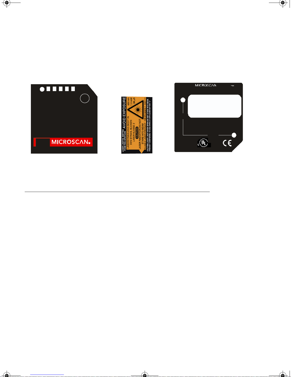
Product Labels
The following labels are located on the top, side, and bottom of the MS-3 FIS-0003
Reader:
PWR
40%
60%
11-000063-01
20%
MS-3
80%
ST
100%
GR
LASER
www.micros can.com1201SW 7th St.
TEST
helpdesk@micr oscan.com
0.85"
(21,6mm)
THISDEVICE COMPLIES WIT HPART 15O FT HEF CC RULES.
OPERATION IS SUBJECT TOT HE FOLLOWINGTWOCONDI TIONS. (1)
THISDEVICE MAYNOT CAUSE HARMFUL INTERFERENCE,AND( 2)T HIS
DEVICE MUST ACCEPTANY I NT ERFERENCE RE CEIVED,I NCLUDI NG
INTERFERENCETHATM AY CAUSE UNDESIREDO PERATION.
Rent on, WA 98055
1.25"
(31,8mm)
LISTED
UL6 0950
R
US
4k 68
11-00006 2-01
5V
2Watts max.
CLASS B DEVICE
Mad e i n US A
TopTop Side Bottom
Approvals
This equipment is in compliance or approved by the following organizations:
• CDRH (Center for Devices & Radiological Heal th)
• UL (Underwriters Laboratories, Inc.)
• cUL (UL mark of Canada)
• FCC (Federal Communication Commission)
•CE Compliant
• BSMI (Bureau of Standards, Metrology and Inspection)
x MS-3 Laser Scanner User’s Manual
Page 11
MS-3 Laser E.book Page xi Monday, August 30, 2004 11:09 AM
Warning and Caution Summary
This equipment has been tested and found to comply with the limits for a Class A digital
device, pursuant to part 15 of the FCC Rules. These limits are designed to provide rea
sonable protection against harmful interference in a residential installation. This equipment generates, uses, and can radiate radio frequency energy, and, if not installed and
used in accordance with the instructions, may cause harmful interference to radio com
munications. However, there is no guarantee that interference will not occur in a particular installation. If this equipment does cause harmful interference to radio or television
reception, which can be determined by turning the equipment off and on, the user is
encouraged to try to correct the interference by one or more of the following measures:
• Reorient or relocate the receiving antenna.
•Increase the separation between the equipment and receiver.
• Connect the equipment into an outlet on a circuit different from that to whi ch th e
receiver is connected.
• Consult the dealer or an e xper ien ce d radio/TV te ch nici an for hel p.
For connection to a UL Listed direct plug-in power unit marked Class 2 and rated at
VDC at 2 Amps or greater.
5
European models must use a similarly rated Class I or Class II power supply that is cer-
-
-
tified to comply with standard for safety EN 60950.
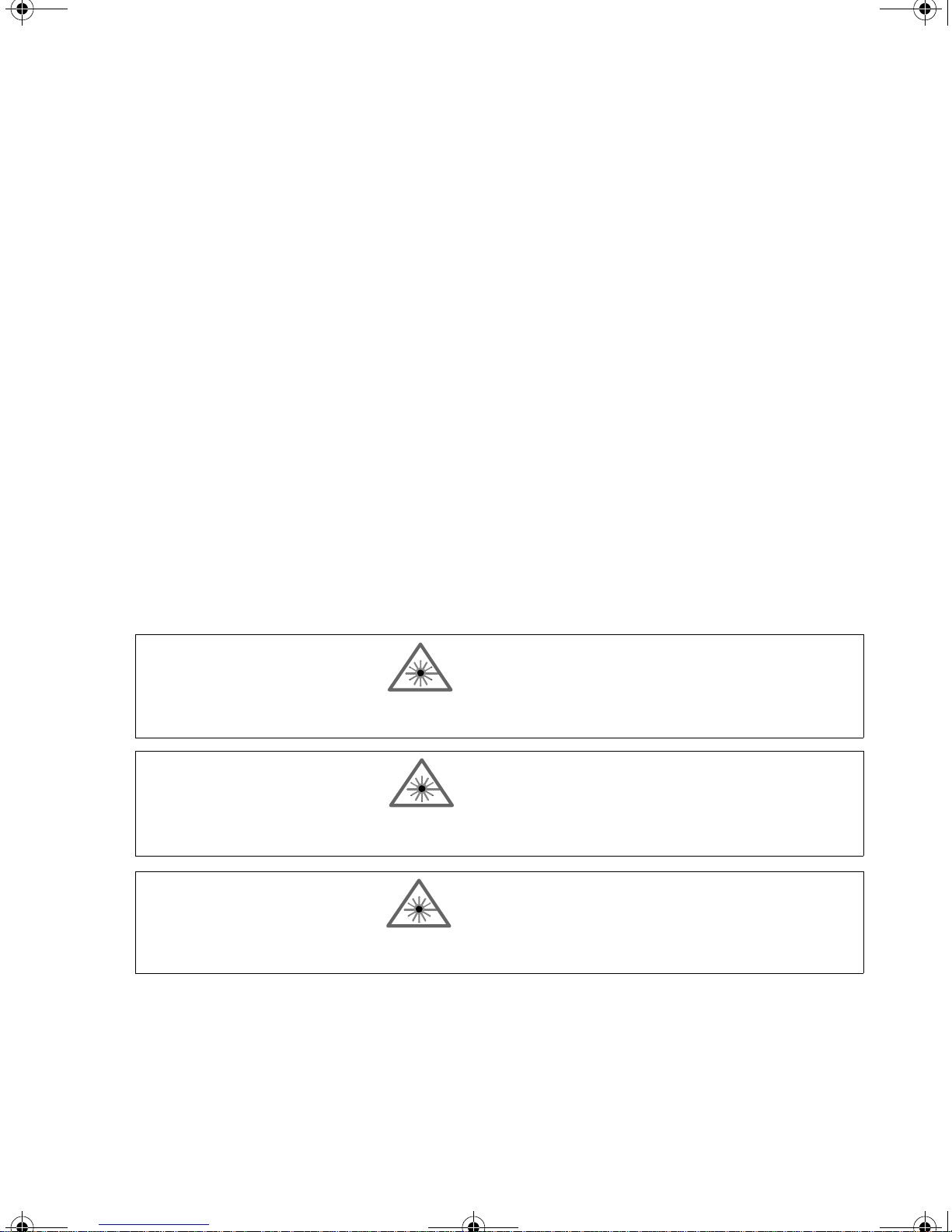
WARNING
Use of controls, adjustments, or performance of procedures other than those specified
herein may result in hazardous laser ligh t radiation expo sure.
WARNING
There are no user serviceable parts in the scanner. Open ing the scann er voids the Mi croscan Systems warranty and could expose the us er to laser diode powe r of up to 7 mW.
WARNING
The laser beam can be harmful to eyesight. Avoid eye contact with the laser beam.
Never point the beam at other people, or in a direction where people may be passing .
MS-3 Laser Scanner User’s Manual xi
Page 12

MS-3 Laser E.book Page xii Monday, August 30, 2004 11:09 AM
xii MS-3 Laser Scanner User’s Manual
Page 13

MS-3 Laser E.book Page 1 Monday, August 30, 2004 11:09 AM
Chapter
Chapter
1
1
Quick Star t
Chapter Contents
Step 1 Hardware Required..........................................................................1-2
Step 2 Connect the System.........................................................................1-3
Step 3 Position Symbol and Scanner..........................................................1-4
Step 4 Install ESP .......................................................................................1-5
Step 5 Select Scanner Model......................................................................1-6
Step 6 Autoconnect.....................................................................................1-7
Step 7 Test for Read Rate...........................................................................1-8
Step 8 Calibrate the Scanner......................................................................1-9
Step 9 Save Calibration Settings for Power-on.........................................1 -10
Step 10 Configure the Scanner.................................................................1-11
This section is designed to get the scanner up and running quickly so the user can get a
sense of its capabilities and test sample bar code symbols. Detailed setup information
for configuring the scanner for your specific application can be obtained in the subse
quent chapters.
-
MS-3 Laser Scanner User’s Manual 1-1
Page 14

MS-3 Laser E.book Page 2 Monday, August 30, 2004 11:09 AM
Step 1 — Hardware Required
Caution: If using your own power supply (see “Warning and Caution Summary” on
page i-xi), be certain that it is wired correctly and supply voltage is 10 to 28 VDC.
Incorrect wiring or voltage can cause software or equipment failures.
If connecting to a host with an IB-131 Interface box, you will need the following:
a
Item
1 FIS-0003-1XXX MS-3 laser scanner
2 FIS-0001-0029 IC-331 Interface converter
3 99-400005-02 IB-131 Interface box
4 Host computer
5 P/N 61-300026-01 Null modem configuration cable
97-100004-05 (120VAC)
6
97-100004-06 (240VAC)
7 99-4400001-10 Optional object detector
Part Number Description
Power supply
a. See figure 1-1 for diagram of system.
3
4
Scanner
Host
5
6
1
2
Network
7
Figure 1-1 Hardware Required
1-2 MS-3 Laser Scanner User’s Manual
Page 15
MS-3 Laser E.book Page 3 Monday, August 30, 2004 11:09 AM
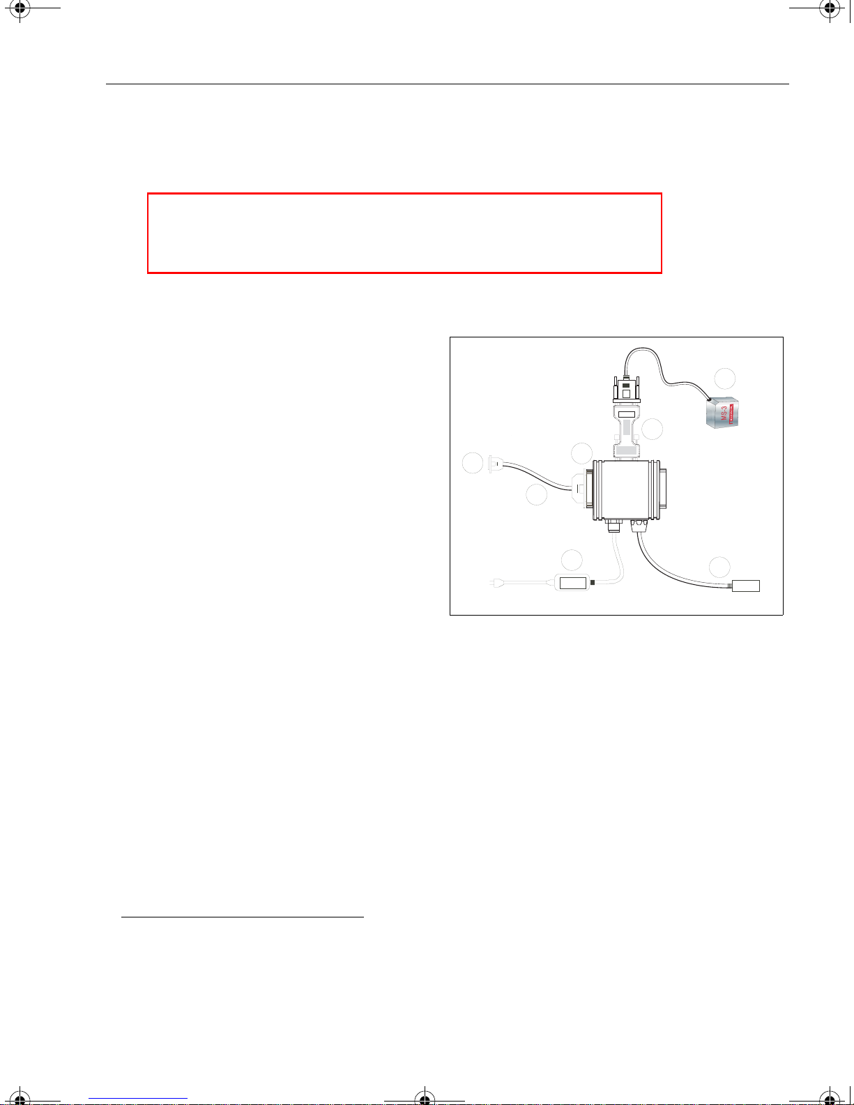
Step 2 — Connect the System
Caution:
• Be sure all cables are connected BEFORE applying power.
• Always power down BEFORE disconnecting any cables.
To connect the system, do the following:
1. Connect the scanner (1) to the
“SCANNER” connector on the
IC-331 interface converter (2)
using the attached 3-foot cable.
2. Connect the IC-331 directly to the
“SCANNER” 15 pin connector on the
IB-131 (3).
3. Connect the host computer (4) to
the IB-131 “HOST” 2 5 -pi n c onn ec
tor via the null modem cable (5).2
(Refer to “IB-131 Interface” on
page A-8 for pin connections.)
4. Connect power su pply (6) t o the
IB-131 “POWER” connector.
5. Apply power to the system.
Chapter 1 Quick Start
1
2
3
4
-
5
6
Scanner
Host
Network
Figure 1-2 Hardware Connections
1
7
1. Since power supply is included in the single cabling assembly, the reader cable should not
exceed 3 feet. RS232 cabling from the IB-131 to the host can be up to 47 feet provided it does
not include power input.
2. If using your own null modem RS232 host cable, be certain that the host’s TxD connects to the
reader’s RxD and the reader’s TxD connects to the host’s RxD.
MS-3 Laser Scanner User’s Manual 1-3
Page 16
h
t
is
Skew
S
MS-3 Laser E.book Page 4 Monday, August 30, 2004 11:09 AM
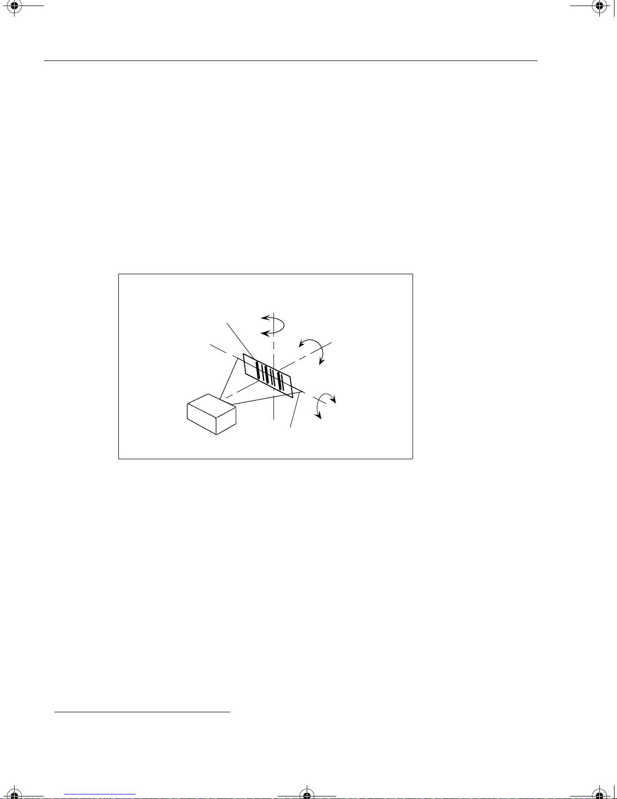
Step 3 — Position Symbol and Scanner
Note: Code 39 is the default code type enabled. If you are uncertain as to your symbology type, enable all codes by selecting the Auto Discriminate macro in Terminal
mode.
1. Set up a symbol at the scanning distance you are using in your application.
(See “Read Ranges” on page A-3.)
2. Avoid bright light or IR light from other sources, including other scanners.
3. Pit ch sym b ol or sc anne r slight ly to avoid specular reflection, the return of direct,
non-diffused light.
1
Bar code
symbol
canner
axis
Til
ax
Pitc
axis
Scan line
Figure 1-3 Symbol/Scanner Position
Note: If u s i ng a n I 2 / 5 sy m bol , verify that the number of characters in the symbol being
scanned matches the symbol length enabled for the I 2/5 symbol type. (Default is 10 and 6 .)
See “Interleaved 2 of 5” on page 5-13.
1. Consult table A-1 and table A-2 on page A-3.
1-4 MS-3 Laser Scanner User’s Manual
Page 17

MS-3 Laser E.book Page 5 Monday, August 30, 2004 11:09 AM
Step 4 — Install ESP
(ESP is short for Easy Setup Program.)
With your scanner connected to a host computer with Windows™ operating system, you
can use the ESP to configure and control the reader.
1. In se rt you r Mi cr osca n CD in to your computer’s CD drive.
2. Launch Setup.exe under ESP and follow the prompts.
If downloading from the web:
a) Go to http://www.microscan.com/esp
b) Enter c om pany inf ormat io n.
c) Select ESP and download to your computer hard drive.
d) Extract ESP WinZip files to a directory of your choice.
3. Note where your ESP.exe file is stored on your hard drive.
At the end of the install process, you should see the following icon on your
desktop:
Chapter 1 Quick Start
4. Click t he ESP icon to start the program.
MS-3 Laser Scanner User’s Manual 1-5
Page 18
MS-3 Laser E.book Page 6 Monday, August 30, 2004 11:09 AM
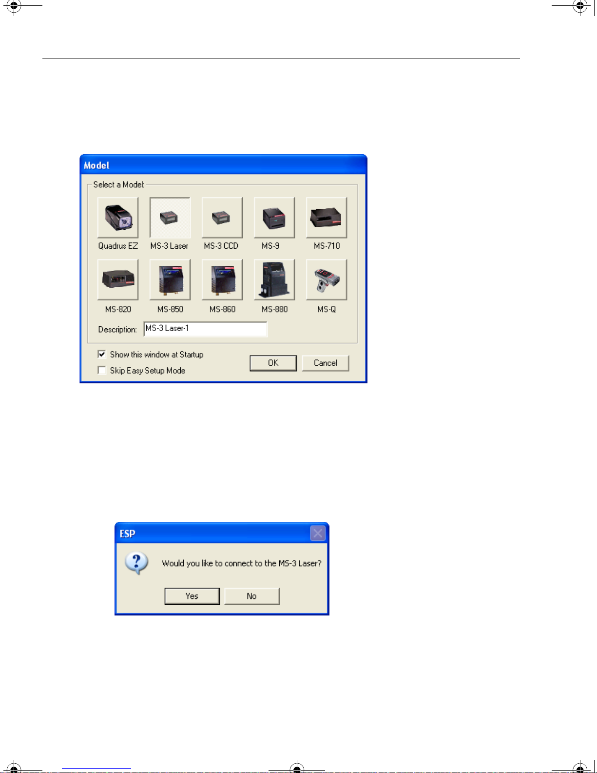
Step 5 — Select Reader Model
When you start the program, the following menu will appear.
Note: If you need to select another model later, you can find it in the App Mode under
Model on the menu bar.
1. Select MS-3 laser from the menu and click OK.
If you do not want to make this selection every time you load ESP, uncheck Show
this window at Startup.
2. Select the default name, for example MS-3 Laser-1, or type in a file name of
your choice and click OK.
3. Click Yes when the connect to the reader dialog appears.
1-6 MS-3 Laser Scanner User’s Manual
Page 19
MS-3 Laser E.book Page 7 Monday, August 30, 2004 11:09 AM
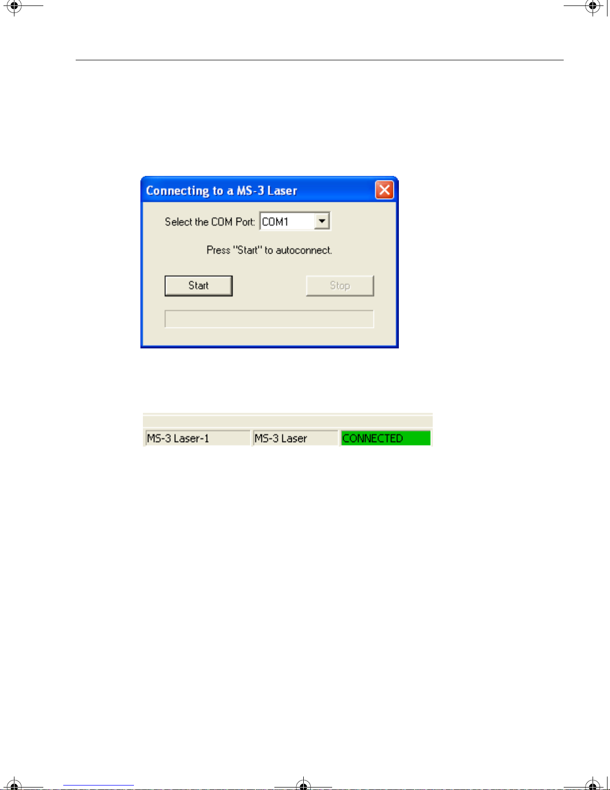
Step 6 — Autoconnect
1. In the Connecting to... dialog, if your com mun icat ions port i s not the defau lt
COM1, use the pull down arrow to change your communications port.
Chapter 1 Quick Start
2. Click t he Start button.
When connected, the CONNECTED message will app ear i n a g reen bo x in th e sta -
tus bar on the bottom right of the dialog.
3. If connection fails, enable a different Com port, check connections, and try again.
Tip: If you do not see either the CONNECTED or DISCONNECTED message at the bottom of your dialog, try expanding the ESP window horizontally.
Important Note: When you connect to the reader, the reader’s settings will be loaded
into ESP.
MS-3 Laser Scanner User’s Manual 1-7
Page 20

MS-3 Laser E.book Page 8 Monday, August 30, 2004 11:09 AM
Step 7 — Test for Read Rate
With this test you can learn the percentage of decodes per images captured by observing the LEDs (20% through 100%) on the top of the MS-3 which are active during a
read rate test. If the results are not satisfactory, move on to
on page 1-9.
By ESP
After connecting to the scanner, ESP will open in Easy Setup Mode.
1. Click t he Test button in Easy Setup Mode to begin the read rate test.
“Calibrate the Reader”
2. Follow th e in st ru ct ions in Easy Setup Mode screen.
3. To end the Read Rate test, click the Stop button.
By the Test Button
Test Button
1. Press and hold the TEST button
on the MS-3 until you hear one
beep and see one LED momen
tarily turn amber . This will signal
the beginning of the read rate
routine.
2. To end the read rate test press
the TEST button and quickly
release.
1
-
Read rate
performance
LEDs
TEST
100%STGR
80%
60%
40%
20%
PWR
1 1- 0000 63-0 1
r
e
s
a
L
3
-
S
M
1. This assumes that the default functions of the test button have not been re-programmed.
1-8 MS-3 Laser Scanner User’s Manual
Page 21
MS-3 Laser E.book Page 9 Monday, August 30, 2004 11:09 AM
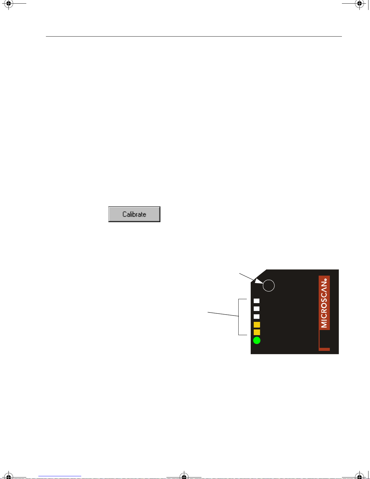
Step 8 — Calibrate the Reader
If , after doing the read rate test, the results are not satisfactory, try the calibration routine.
During the calibration routine, the scanner attempts various settings to determine the
optimum decode rate for the given conditions. In this process it might do the following:
Chapter 1 Quick Start
• Adjust laser power
• Adjust mirror motor speed
•Adjust AGC gain
The test will end automatically when the optimum combination of settings has been
achieved.
• Enable Autodiscrimination
(read several symbol types)
By ESP
Click the Calibrate button in Easy Setup Mode to begin the read rate test.
You can observe the progress of the calibration routine on the Calibration popup.
Note: You can also calibrate the scanner in the Calibration menu in the Apps Mode.
By the Test button
Press and hold the TEST button
until you hear two beeps and see
two amber performance LEDs turn
amber to indicate that the calibra
tion is in progress.
The scanner will beep once at the
end of calibration.
-
Read rate
performance
LEDs
Test Button
TEST
100%STGR
80%
60%
40%
20%
PWR
11-000063-01
R
E
S
A
L
3
-
S
M
Figure 1-4 Calibration
MS-3 Laser Scanner User’s Manual 1-9
Page 22
MS-3 Laser E.book Page 10 Monday, August 30, 2004 11:09 AM
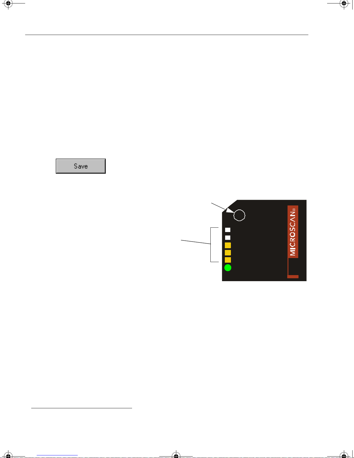
Step 9 — Save Calibration Settings for Power-on
After calibrating the MS-3, you can save your new settings to be av ailable on power-on.
By ESP
Caution: If you have settings in the scanner that you have not yet loaded into ESP, the
ESP settings will overwrite the scanner’s settings when you save. Under these condi
tions, it is highly recommended that you first do Receive Reader Settings before you
save for power-on.
After testing and/or calibrating the scanner, you can save the settings for power-on by
clicking the Save button.
-
By the Test Button
Press and hold the TEST button until
you hear three beeps and see three
performance LEDs momentarily turn
amber.
1
Test Button
Read rate
performance
LEDs
Figure 1-5 Save Settings
TEST
100%STGR
80%
60%
40%
20%
PWR
1 1- 0000 63-0 1
R
E
S
A
L
3
-
S
M
1. This assumes that the default functions of the test button have not been re-programmed.
1-10 MS-3 Laser Scanner User’s Manual
Page 23
MS-3 Laser E.book Page 11 Monday, August 30, 2004 11:09 AM
Step 10 — Configure the Reader
See the succeeding chapters and Appendices to see specific configuration command
explanations for both ESP and serial commands.
By ESP
To change reader settings, or to access the utilities or terminal window, click on the
App Mode button.
Chapter 1 Quick Start
See Chapter 2, “Using ESP.”
By Serial Commands
From your terminal program or the terminal screen in ESP, you can enter serial string
commands and configuration and utility commands as described in this manual.
See “Serial Configuration Commands” on page A-13 and “Summary of Utilities
Commands” on page 11-3.
Note: Y ou can learn the current setting of any parameter by inserting a question mark
after the number, as in <K100?> To see all “K” commands, send <K?>.
MS-3 Laser Scanner User’s Manual 1-11
Page 24

MS-3 Laser E.book Page 12 Monday, August 30, 2004 11:09 AM
1-12 MS-3 Laser Scanner User’s Manual
Page 25

MS-3 Laser E.book Page 1 Monday, August 30, 2004 11:09 AM
Chapter
2
Setup Mode.................................................................................................2-2
Application Mode.........................................................................................2-3
Pulldown Menus.................................. ................................. ... ... .................2-4
Connect Menu............................... ... ................................. ... .......................2-9
View...........................................................................................................2-11
Navigating in ESP .....................................................................................2-12
Send/Receive Options...............................................................................2-13
Using ESP
Chapter Contents
This section is designed to help you understand the structure, elements, and application
of the ESP (Easy Setup Program).
When you start up ESP, unless otherwise specified, you will enter the Setup Mode for
initial setup. From there, you move easily into the App Mode (application mode) where
you can access several configuration and utilities menus.
MS-3 Laser Reader User’s Manual 2-1
Page 26
MS-3 Laser E.book Page 2 Monday, August 30, 2004 11:09 AM
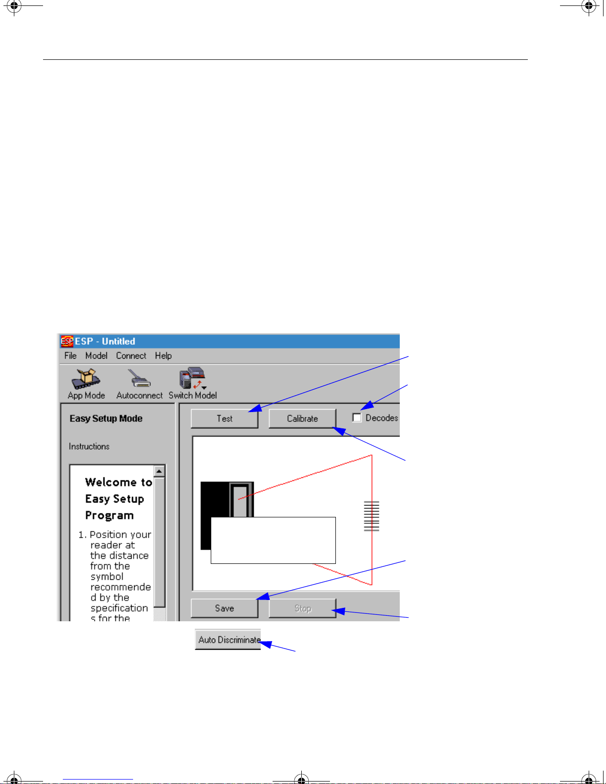
Setup Mode
Setup Mode
In Setup Mode you are presented with the Test option and if appropriate for your
application, Calibration. After connecting to your scanner (or reader) the Setup Mode
will first appear. This will provide you with instructions specific to your model that will
help you in positioning, testing, and if appropriate, calibrating.
Test
Click the Test button to start the read rate test for a quick indication of the read capabilities and the limits of your application. When Decodes per Second is unchecked,
the test will count the percentage of decodes relative to the number of actual scans.
Click Stop to end the test.
Calibrate
Some models include a calibration routine that will optimize reads by comparing read
rates at various settings in focal lengths, scan speeds, and gain settings.
Test button
Click here to change
from percentage of
good decodes to
decodes per second
Calibration is available on some models
Note: This view may be
slightly different for each
model.
Saves Calibration
results (if available)
2-2 MS-3 Laser Reader User’s Manual
Ends the read rate
test
On some models, clicking Auto Discriminate
will enable most available symbology types.
Page 27
MS-3 Laser E.book Page 3 Monday, August 30, 2004 11:09 AM
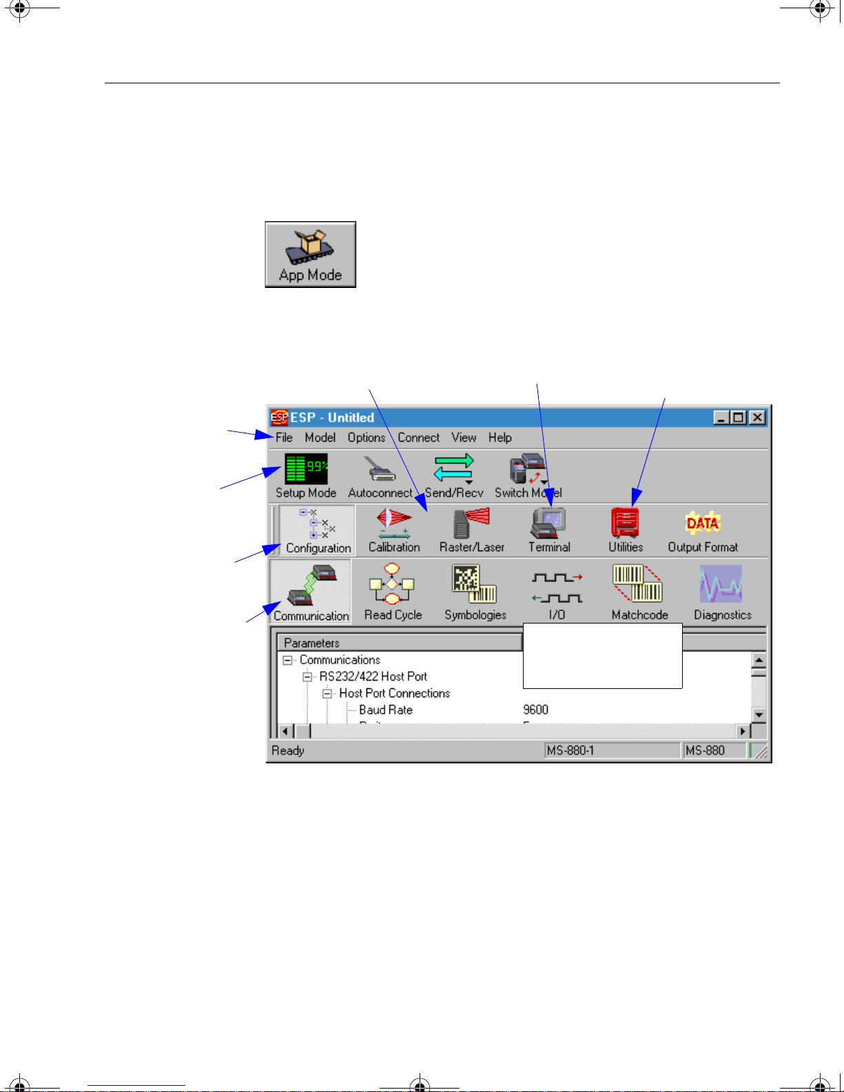
Application Mode
From Setup Mode, you can click on the App Mode button to access specific configuration menus, utilities, and a terminal window where serial commands can be entered.
Note that the App Mode and Setup Mode buttons appear in the same position to allow
easy switching between these primary modes.
Chapter 2 Using ESP
Pulldown menus
Click this icon to
return to Easy
Setup mode
Click this icon to
return to this view
from Utilities or
Terminal
Click on icons in this
toolbar to access
configuration menu
trees to make specific changes in configuration
The icons on this
toolbar are for operations
Click here to open
a terminal window
Note: This view may be
slightly different for
each model.
Click here to
access read rate
and other utilities
Note: For specific information on any of the icons shown abov e in the operations bar or
configuration bar, see specific chapters in this document.
MS-3 Laser Reader User’s Manual 2-3
Page 28
MS-3 Laser E.book Page 4 Monday, August 30, 2004 11:09 AM
Pulldown Menus
Pulldown Menus
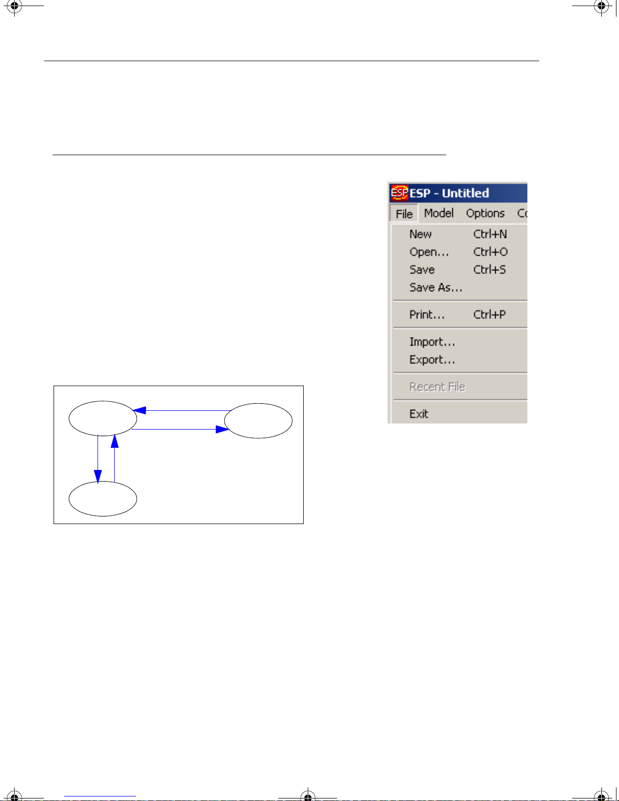
File
New
Whenever New is selected, the default configuration of
ESP is loaded.
Open/Save
When Save or Save As is selected, the ESP configuration is saved to the host computer’s hard drive and
available whenever the same file is selected under
Open.
Important: When you save menu changes to your
hard drive, these changes are not saved to your reader.
Figure 2-1 shows how settings can be saved and
received between ESP and the reader and ESP and the
host hard drive.
Receive Reader Settings
ESP
Save to Reader
File
Save
Host hard
drive
Figure 2-1 How Settings are Saved
File
Open
Reader
Import/Export
Import converts the ASCII settings from a text file to ESP configuration s ettings.
Export converts the active ESP co nfigurat ion settings to an ASCII text file.
2-4 MS-3 Laser Reader User’s Manual
Page 29
MS-3 Laser E.book Page 5 Monday, August 30, 2004 11:09 AM
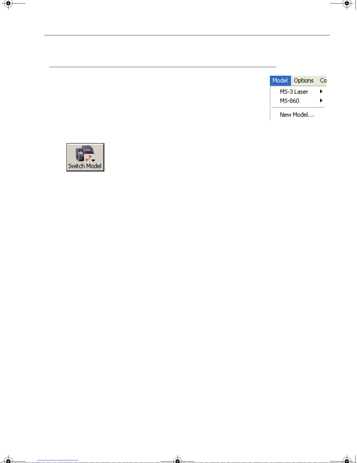
Model
In Model you can select between models. When you choose
another model, your current connection with your present model
will be terminated.
To connect to another model, select New Model, choose a new
model and click OK.
Note that all the models you have enabled by selecting will continue to appear in the Model menu and that the same menu is
repeated when clicking the Switch Model icon.
Chapter 2 Using ESP
When you save your ESP file, you will be saving the settings of all the models defined in
a single ESP file.
MS-3 Laser Reader User’s Manual 2-5
Page 30
MS-3 Laser E.book Page 6 Monday, August 30, 2004 11:09 AM
Pulldown Menus
Options
You can use the Options menu
save memos and set up ESP
Preferences.
Note: Preferences will be saved
and be loaded into ESP when
ESP is opened next, whether or
not you save the ESP file to the
computer.
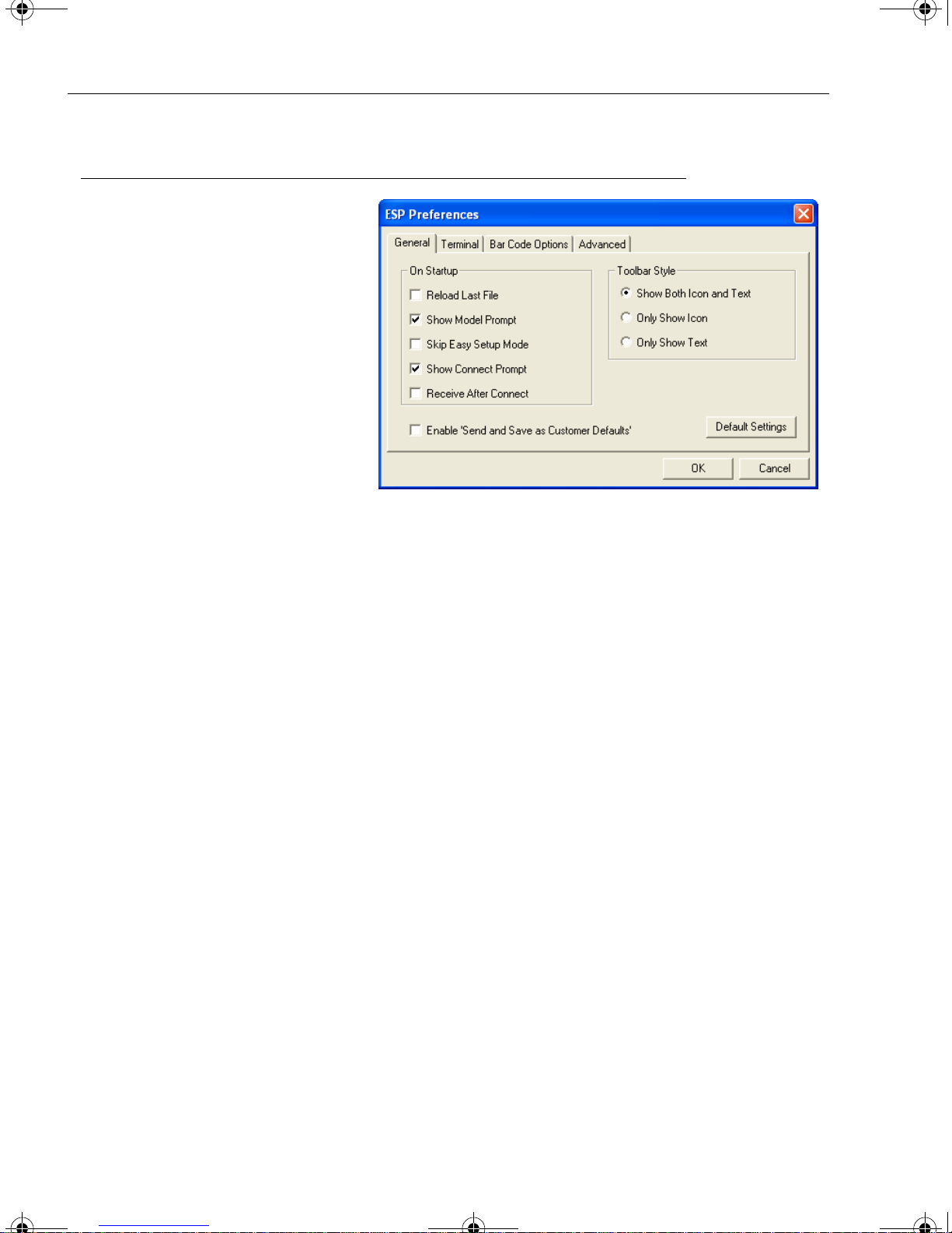
Preferences
General tab
Reload Last File
At startup, reloads the last file
saved to the computer.
Show Model Prompt
At startup, remembers the last connected model and displays it in the Connecting...
dialog whenever you attempt to connect.
Skip Easy Mode
At startup, Skips the Easy Mode and opens directly in the application mode.
Show Connect Prompt
At startup, displays the Would you like to connect... prompt.
Receive After Connect
At startup, loads the reader’s settings into ESP. (This is not recommended if you want to
preserve your ESP settings for future use.)
Enable ‘Send and Save as Factory Settings’
At startup, enables the Send and Save as Factory option in the Send/Recv command.
2-6 MS-3 Laser Reader User’s Manual
Page 31

MS-3 Laser E.book Page 7 Monday, August 30, 2004 11:09 AM
Terminal tab
When Show Non-Printable
Characters is checked, charac
ters such as CRLF will be displayed in the terminal window.
When Enhanced Format is
checked, the characters are dis
played with more detailed formatting.
Change Keyboard Macros
In this dialog you can first select
the function key and then enter
your macro keystrokes in the
associated key map. For exam
ple, to make Ctrl-F5 the keystroke to enable send a trigger
character, select F5, then in the
Ctrl row, enter <trigger character> and click OK. Then whenever the Ctrl-F5 key
stroke is pressed, the trigger character will start the read cycle.
Chapter 2 Using ESP
-
-
-
-
Change Font
Sets the font characteristics for the commands that you type in the terminal window.
Change Echo Font
Sets the font characteristics for text that is echoed back to the screen from the reader.
Toolbar Style
By user selection, displays toolbar buttons as icons, text only, or both (default).
Note: See also Chapter 14, “Terminal Mode.”
MS-3 Laser Reader User’s Manual 2-7
Page 32

MS-3 Laser E.book Page 8 Monday, August 30, 2004 11:09 AM
Pulldown Menus
Bar Code Options tab
Sets up the sizing, font, and
caption parameters for the bar
codes that you can create and
print from the Bar Code
Options Dialog under View.
Sizing Information
Sets the bar height (in inches)
and bar widths (in thousands of
an inch) of the symbols. A bar
width of 13 is 0.013 inches.
Caption
Sets the characteristics of caption font and its placement in
relation to the bar code symbol.
Advanced tab
As indicated.
Document Memo
Whatever you type into the Document Memo will appear in a text box whenever your
cursor hovers over the Document Memo option.
Model Memo
Memos created in Model Memo are specific to the model enabled when the message
was created.
2-8 MS-3 Laser Reader User’s Manual
Page 33

MS-3 Laser E.book Page 9 Monday, August 30, 2004 11:09 AM
Connect Menu
Autoconnect
Generally Autoconnect will be the quickest way that ESP
can get connected to a reader. Autoconnect will try con
necting at the most common communications settings and
step through the various settings until they match up with
the host’s settings.
Connect
When you select Connect, you will need to manually select the communications settings from a popup dialog.
Chapter 2 Using ESP
-
Configure Multidrop
To connect to the reader by Multidrop, you will need a multidrop concentrator such as
the MS-5000 and the required power supplies and cabling to communicate with your
scanner(s).
1. From the Communications drop down menu in
ESP, select Configure Multidrop to bring up the
Multidrop Settings dialog.
2. If ne ce ssa ry, change the default address to
match the address of your multidropped scanne r
and click OK.
If the host serial port is no t co nnec ted in ESP,
you will see the following popup message:
ESP is not currently connected to the multidrop
concentrator. Do you wish to establish a connec
tion now?
3. Click Yes.
You will see a Serial Communication Parameters dialog as shown on the next
page.
-
MS-3 Laser Reader User’s Manual 2-9
Page 34

MS-3 Laser E.book Page 10 Monday, August 30, 2004 11:09 AM
Connect Menu
4. Select the concentrator’s host port communications
settings.
When you click Connect, you will be connecting to
your concentrato r, which can then relay commands to
the scanner whose address w as set in the Multidrop
Settings dialog.
5. Click Connect.
6. You should see the CONNECTED message in green
at the bottom of the window along with the scanner’ s
Multidrop address.
7. Do Retrieve Scanner Settings to upload scanner’s
configuration (Step 4). If upload fails, return to the
Serial Communication Parameters dialog and make the corrections.
8. Follow the same procedure for connecting other scanners to your
multidrop network.
Note: For more information, see your scanner user’s manual or Microscan’s MS-5000
Multidrop Concentrator User’s Manual, 83-005000.
2-10 MS-3 Laser Reader User’s Manual
Page 35

MS-3 Laser E.book Page 11 Monday, August 30, 2004 11:09 AM
View
View indicates the current view (with a dot before the item)
and allows you to quickly move to other views which are also
accessed by clicking the icons on the toolbars.
It also allows you to access the Barcode Dialog.
Barcode Dialog
In the Barcode Dialog you can create bar code symbols by directly typing in the text bar
code text you want to appear in Code 128 bar code symbols. This is a very useful tool
for creating configuration symbols which allows you to configure your reader by reading
the bar code symbols you print out. To configure the size, text and caption parameters,
“Bar Code Options tab” on page 2-8.
see
Chapter 2 Using ESP
MS-3 Laser Reader User’s Manual 2-11
Page 36

MS-3 Laser E.book Page 12 Monday, August 30, 2004 11:09 AM
Navigating in ESP
Navigating in ESP
To change reader settings, or to access the utilities or terminal window, click on the
App Mode button.
To return to the Easy Mode, click on the EZ Mode button.
To make changes to a configuration setting in the menu trees:
1. Left click on the + to
expand tree
2. Double click on parameter and click once in selection box to view options.
3. Place your curser in the
selection box, scroll down
to the setting you want to
change and click once on
the setting.
4. Left click again on the
open screen to complete
the selection.
5. Right click on the open screen and select
Save to Reader to implement the command
in the reader.
2-12 MS-3 Laser Reader User’s Manual
Page 37

MS-3 Laser E.book Page 13 Monday, August 30, 2004 11:09 AM
Send/Receive Options
To access Receive, Save and Default options, click the Send/Recv
button:
configuration views.
Receiving
From the Send/Recv selector, select Receive Reader Settings.
Caution: Do no select this option if you do not want to upload the reader’ s settings. For
example, if your ESP file has a number of custom settings that you want to maintain
and download into the reader, these settings would be lost by choosing Yes.
This is useful if you want to receive (upload) the reader’s settings and save them as a
computer file for later retrieval. For example, if your reader has settings that you do not
want to change, choosing Yes would allow you to load those settings to ESP and save
as an ESP file for later retrieval.
Receiving the reader’s settings will also assure that you will not be subsequently saving
any unwanted changes that you or someone else previously made in ESP.
See “Send/Receive Options” on page 2-13 for more detail.
You can also access this selector by right -clicking in any of the
Chapter 2 Using ESP
Saving
1. Send, No Save.
(same as <A>)
This saves ESP settings to current
memory.
2. Send and Save.
(same as <Z>)
This activates all changes in current memory and saves to the reader for
power-on.
3. Send and Save as Customer Defaults.
(same as <Zc>)
(This option will be visible only if you had checked Enable ‘Send and Save as
Customer Defaults’ in ESP Preferences in the Options menu.)
Use this to save y our own set of defa ult settings that you can quickly retri eve with
a <Zrc> command.
For more on defaulting and saving settings, see “Defaulting/Saving/Resetting” on
page A-20.
MS-3 Laser Reader User’s Manual 2-13
Page 38

MS-3 Laser E.book Page 14 Monday, August 30, 2004 11:09 AM
Send/Receive Options
Defaulting
When you select Default Current... or Default all ESP... you are only defaulting the
ESP settings.
Advanced Options
Send Current View
This is the same as Save
to Reader, Send No Save
except that only the com
mands in the current menu
tree are sent.
Send Current Command
This is the same as Send
Current View above, but
only saves the command
that is currently selected.
-
Add Exceptions
After you perform a Receive from Reader command1 and you click on the Add Exception option
you may see a list of serial commands that looks
like the example to the right.
mands that may be in your reader’s firmware, but
not included or different from your current ESP
software.
Y ou can edit these commands by double-clicking on
them and changing as needed.
When exceptions are present, you can also access
them from an Exceptions button that will appear
on the Applications button bar.
It is important to note that these
commands will be saved to your reader whenever you do a Save to
Reader command or send an <A> or a <Z> command.
Also, if there is a corresponding ESP menu item, the ESP Value column
for that item will be blank following a Receive from Reader com
mand.
These are serial com-
-
1. From the Send/Recv button or right-clicking from within the tree menus.
2-14 MS-3 Laser Reader User’s Manual
Page 39

MS-3 Laser E.book Page 1 Monday, August 30, 2004 11:09 AM
Chapter
3
Communications
Chapter Contents
Communications by ESP.............................................................................3-2
Communications By Serial Command.........................................................3-2
Password Protection ...................................................................................3-3
RS-232/422 Host Port.................................................................................3-4
RS-232 Auxiliary Port................................................................................3-11
Preamble...................................................................................................3-20
Postamble ................................................................................................. 3 -21
LRC Status................................................................................................3-22
Intercharacter Delay..................................................................................3-22
The ESP™ (Easy Setup Program), configuration changes can be made in the ESP
menus, then sent and saved to your reader. The user can also send serial commands to
the reader via the ESP’s Terminal window.
This section includes connecting parameters and options for communicating by the auxiliary port and various interfaces.
Note: When assigning characters in user-defined fields, the characters NULL <> and ,
can only be entered through embedded menus, not through ESP or serial commands.
Note: Y ou can learn the current setting of any parameter by inserting a question mark
after the number, as in <K100?>. To see all “K” commands, send <K?>.
Note: Default settings for establishing communications are:
Baud = 9600
Parity = Even
Stop Bits = One
Data Bits = Seven
Flow Control = None
Note: Y ou can learn the current setting of any parameter by inserting a question mark
after the number, as in <K100?> To see all “K” commands, send <K?>.
MS-3 Laser Scanner User’s Manual 3-1
Page 40

MS-3 Laser E.book Page 2 Monday, August 30, 2004 11:09 AM
Communications by ESP
Communications by ESP
Click this button to bring up
the Communications menu.
To change a setting,
double-click the set-
ting and use your cursor to scroll through
the options.
To open nested options,
single-click the +.
Note: Y ou can learn the current setting of any parameter by inserting a question mark
after the number, as in <K100?> To see all “K” commands, send <K?>.
Communications By Serial Command
Command Title Format
Password Status <K732, status>
Password Entry, Change <K733 password,new password>
Host Port Parameters <K100,baud,parity,stop bits,data bits>
Host Protocol <K140, protocol>
Host RS422 Status <K102, status>
Aux Port Parameters
Preamble <K141,preambole status,preamble>
Postamble <K142,postamble status,postamble>
LRC Status <K145,status>
Intercharacter Delay <K144,intercharacter delay>
<K101,aux port mode,baud rate,parity,stop bits,data
bits,daisy chain status,daisy chain ID>
3-2 MS-3 Laser Scanner User’s Manual
Page 41

MS-3 Laser E.book Page 3 Monday, August 30, 2004 11:09 AM
Password Protection
Note: Password protection options are entered serially and are not available in ESP
menus.
Usage: Password Protection when enabled preve nts the sca nner’ s p ar ameters
from being modified but does not affect the flow of data from the scanner
or its response to read only commands.
Definition: Can require a password for any serial or menu command change.
Password
Entry:
If you enter the password correctly , you will see the password echoed to the screen and
you will then be able to make changes to the scanner’s parameters.
Enter the password once and the scanner’s command protection is temporarily
unlocked until the scanner is turned off or reset. If a reset occurs then the password will
need to be entered again.
From a terminal screen enter <K733 password>.
(Do not put a comma between K733 and the password.)
Chapter 3 Communications
Password Status
Definition: If Password Status is set to Disabled, then no parameters are off lim-
its.
If Password Status is set to Enabled, then this option cannot be subse-
quently disabled until the password defined in <K733> is entered. This
parameter is non-volatile and will be included in any <Z> or <Zc>
parameter save.
Serial Cmd: <K732,status>
Default: Disabled
Options: 0 = Disabled 1 = Enabled
New Password
Definition: To change the password from the current password, enter the current
password, a comma, and the new password. If successfully entered, the
new password will be displayed and the command change protection
temporarily removed.
Serial Cmd: <K733 password,new password>
Note: Follow this with a <Z> or <Zc> to save for power-on.
Default: MICRO
Options: Any ASCII string up to 8 characters.
MS-3 Laser Scanner User’s Manual 3-3
Page 42

MS-3 Laser E.book Page 4 Monday, August 30, 2004 11:09 AM
RS-232/422 Host Port
RS-232/422 Host Port
Host Port Connections
Baud Rate (host port)
Usage: Can be used to transfer data faster or to match host port settings.
Definition: The rate at which the reader and host transfer data back and forth.
Serial Cmd: <K100,baud rate,parity,stop bits,data bits>
Default: 9600
Options: 0 = 600 3 = 4800 6 = 38.4 K
1 = 1200 4 = 9600 7 = 57.6 K
2 = 2400 5 = 19.2 K 8 = 115.2 K
Parity (host port)
Usage: Only changed if necessary to match host setting.
Definition: An error detection routine in which one data bit in each character is set to
1 or 0 so that the total number of 1 bits in the data field is even or odd.
Serial Cmd: <K100,baud rate,parity,stop bits,data bits>
Default: Even
Options: 0 = None 1 = Even 2 = Odd
Stop Bits (host port)
Usage: Only changed if necessary to match host setting.
Definition: One or two bits added to the end of each character to indicate the end of
the character.
Serial Cmd: <K100,baud rate,parity,stop bits,data bits>
Default: One
Options: 0 = One 1 = Two
3-4 MS-3 Laser Scanner User’s Manual
Page 43

MS-3 Laser E.book Page 5 Monday, August 30, 2004 11:09 AM
Data Bits (host port)
Usage: Only changed if necessary to match host setting.
Definition: Number of bits in each character.
Serial Cmd: <K100,baud rate,parity,stop bits,data bits>
Default: Seven
Options: 0 = Seven 1 = Eight
Host Port Protocol
Usage: In general, the point-to-point protocols will work well in most applica-
tions. They require no address and must use RS-232 or RS-422 communications standards.
Definition: Protocols define the sequence and format in which information is trans-
ferred between the scanner and the host, or in the case of Multidrop,
between scanners and a concentrator.
Serial Cmd: <K140,protocol>
Default: Point-to-Point
Options: 0 = Point-to-Point
1 = Point-to-Point with RTS/CTS
2 = Point-to-Point with XON/XOFF
3 = Point-to-P oint with RTS/CTS &
XON/XOFF
If selecting one of the options from 0 to 4 (Point-to-Point, Point-to-
Point with RTS/CTS, Point-to-Point with XON/XOFF, Point-to-
Point with RTS/CTS and XON/XOFF, or Polling Mode D), use the
<K140,protocol> format.
Option 5 through 7 are special cases and discussed later in this section.
Chapter 3 Communications
4 = Polling Mode D
5 = Multidrop
6 = User Defined
7 = User Defined Multidrop
Point-to-Point (standard)
Usage: Used only with RS232 or RS422.
Definition: Standard Point-to-Point requires no address and sends data to the host
whenever it is available, without any request or handshake from the host.
Serial Cmd: <K140,0>
MS-3 Laser Scanner User’s Manual 3-5
Page 44

MS-3 Laser E.book Page 6 Monday, August 30, 2004 11:09 AM
RS-232/422 Host Port
Point-to-Point with RTS/CTS
Usage: A reader initiates a data transfer with an RT S (request -to-send) tran smis-
sion. The host, when ready, responds with a CTS (clear-to-send) and the
data is transmitted. CTS and RTS signals are transmitted over two dedicated wires as defined in the RS-232 standard.
Used only with RS232.
Definition: Point-to-Point with RTS/CTS (request-to-send/clear-to-send) is a
simple hardware handshaking protocol that allows a reader to initiate
data transfers to the host.
Serial Cmd: <K140,1>
Point-to-Point with XON/XOFF (Transmitter On/Off)
Usage: If an XOFF has been received from the host, data will not be sent to the
host until the host sends an XON. During the XOFF phase, the host is free
to carry on other chores and accept data from other devices.
Used only with RS232.
Definition: This option enables the host to send the XON and XOFF command as a
single byte transmission command of start (^Q) or stop (^S).
Serial Cmd: <K140,2>
Point-to-Point with RTS/CTS & XON/XOFF
Usage: Used only with RS232.
Definition: This option is a combination of Point-to-Point with RTS/CTS and
Point-to-Point with XON/XOFF.
Serial Cmd: <K140,3>
Po lling Mode D
Usage: When in Polling Mode D, an address of 1 is automatically displayed on
the configuration screen. However, during transmission, a 1C hex poll
address (FS) and a 1D hex select address (GS) are substituted for the 1.
Definition: Like Point-to-Point, Polling Mode D requires a dedicated connection to
the host; but unlike Point-to-Point, it requires an address and must
wait for a poll from the host before sending data.
Serial Cmd: <K140,4>
3-6 MS-3 Laser Scanner User’s Manual
Page 45

MS-3 Laser E.book Page 7 Monday, August 30, 2004 11:09 AM
Multidrop
See also Quick Start Help for Multidrop setup.
Usage: The MS-5000 can be used as a concentrator to a single host port connec-
tion.
When Multidrop is selected, the protocol characters for RES, REQ, etc.
are assigned automatically.
Definition: Multidrop allows up to 50 devices to be connected to a single RS485
host, with the scanner assigned an unique address (from 01 to 50).
Multidrop
Addresses:
Options: 01 through 50
Serial Cmd: If selecting Multidrop fan address must be defined and appended to the
Each address has its own separate poll and select address (from 1C to 7F
hex).
command string.
Format: <K100,5,address[01 to 50]>
Chapter 3 Communications
Note: Scanners linking up to a Microscan MS-5000 multidrop concentrator must be
configured in standard multidrop protocol.
User Defined Point-to-Point
Usage: Useful for developing custom protocols in polled or unpolled mode.
Definition: User Defined Point-to-Point allows the user to customize the point-to-
point protocol.
Serial Cmd: <K140,6,RES,address,REQ,EOT,STX,ETX,ACK,NAK,from host>
User Defined Address
Definition: User Defined is considered to be in a polled mode only if an address has
been assigned.
Serial Cmd: <K140,6,RES,address,REQ,EOT,STX,ETX,ACK,NAK,from host>
Default: No address
Options: Any ASCII character except a null.
User Defined Example
Definition: Example: ACK/NAK protocol can be configured using User Defined. The
scanner will transmit data to the host when an ACK is received. If a NAK
or response timeout occurs, the scanner will re-send the data to the host
up to 3 more times before aborting.
Tip: To use User Defined Point-to-Point, first select Point-to-Point
<K100,0> and then User Defined <K100,6>.
Example: To select an unpolled ACK/NAK User Defined protocol with
LRC disabled, send <K100,0><K100,6,,,,,,,^F,^U><Kc0>. ACK and
NAK will be displayed in the menu.
MS-3 Laser Scanner User’s Manual 3-7
Page 46

MS-3 Laser E.book Page 8 Monday, August 30, 2004 11:09 AM
RS-232/422 Host Port
Serial Cmd: <K140,6,RES,address,REQ,EOT,STX,ETX,ACK,NAK,from host>
Default: No assignment
Options: Any ASCII character except a null. Control characters can be used to
define RES through NAK in serial commands.
From Host
Definition: This option allows the handshaking protocol to be initiated from the host,
if not configured in an unpolled mode. Messages sent to the host will
include the scanner’s defined protocol. The status of From Host determines if messages sent from the host to the scanner must include the
defined protocol. If From Host is disabled, the defined protocol is not
included. If From Host is enabled, the defined protocol must be
included.
Serial Cmd: <K140,6,RES,address,REQ,EOT,STX,ETX,ACK,NAK,from host>
Default: Disabled
Options: 0 = Disabled 1 = Enabled
3-8 MS-3 Laser Scanner User’s Manual
Page 47

MS-3 Laser E.book Page 9 Monday, August 30, 2004 11:09 AM
User Defined Multidrop
Note: Any ASCII character except a null (00) and a ^A (01) can be assigned as an
address. Control characters can be used to define RES through NAK in serial com
mands. “Communication Protocol Commands” on page A-11.
Usage: This option is used when connecting to a concentrator or other device
that does not match standard multidrop protocol.
If selecting User Defined Multidrop (7), complete the format by either
choosing new parameters or place commas where unchanged data fields
occur.
Definition: User Defined Multidrop allows the user to customize the polling proto-
col.
Serial Cmd: <K140,7,RES,address,REQ,EOT,STX,ETX,ACK,NAK>
For User Defined Multidrop, first select Multidrop <K140,5>, then
User Defined Multidrop <K140,7...>.
Address: Any single character (02 hex to 7E hex) in the ASCII table can be
assigned as the address character. The character chosen is used as the
poll character and the subsequent ASCII character becomes the select
character. For example, if a ^B (02 hex) is selected as the address, ^C
(03 hex) becomes the select address that the host will use in sending
host select commands.
Chapter 3 Communications
-
Note: Definitions of commands in User Defined and User Defined Multidrop must
be duplicated in host applications to enable poll and select sequences to execute cor
rectly during transmission.
Note: Typically, parameters in User Defined Multidrop are defined by first enabling
Multidrop, then enabling User Defined Multidrop. This pre-loads multidrop charac
ters into the parameters. Then changes are made to individual characters to match the
host or other requirements.
-
-
MS-3 Laser Scanner User’s Manual 3-9
Page 48

MS-3 Laser E.book Page 10 Monday, August 30, 2004 11:09 AM
RS-232/422 Host Port
Host RS-232/422 Status
Used only in Point-to-Point protocol, and not with RTS/CTS.
Usage: Only changed if necessary to match host setting.
Definition: Enables RS422. When RS422 is enabled, RS232 is disabled.
Serial Cmd: <K102,status>
Default: Disabled
Options: 0 = Disabled 1 = Enabled
Whenever RS422 is disabled, RS232 is enabled in the background. However, when Multidrop is enabled, the functioning protocol is RS485 regardless of the displayed status
of RS422. Before enabling RS422, first double-check that Multidrop is not enabled.
3-10 MS-3 Laser Scanner User’s Manual
Page 49

MS-3 Laser E.book Page 11 Monday, August 30, 2004 11:09 AM
RS-232 Auxiliary Port
Note: The aux port cannot be used when the host port is set to RS422 or Multidrop.
As with the host port parameters, the auxiliary terminal’s settings (baud rate, parity,
stop bits, and data bits) must be identical with those of the auxiliary device.
Usage: These commands set the communication parameters with the auxiliary
port which can be used to configure menus, send data to the host, dis
play data transmissions originating from the host of the scanner, and
relay data from other scanners set in tandem (daisy chained). If the
scanner’s host port needs to be dedicated to the host, but configuration
must be done on the fly , the auxiliary port can be set to accept configura
tion changes by Command Processing (page 3-17).
Definition: An auxiliary port connects the scanner to a remote display or to other
scanners that can display or transfer data.
Chapter 3 Communications
-
-
Aux Port Connections
As with the host port parameters, the auxiliary terminal’s settings (baud rate, parity,
stop bits, and data bits) must be identical with those of the auxiliary device.
Baud Rate, Aux Port
Usage: Can be used to transfer data faster or match an auxiliary device.
Definition: The rate at which the scanner and host transfer data back and forth.
Serial Cmd: <K101,aux port mode,baud rate,parity,stop bits,data bits,daisy chain
ID status,daisy chain ID>
Default: 9600
Options: 0 = 600 3 = 4800 6 = 38.4 K
1 = 1200 4 = 9600 7 = 57.6 K
2 = 2400 5 = 19.2 K 8 = 115.2 K
MS-3 Laser Scanner User’s Manual 3-11
Page 50

MS-3 Laser E.book Page 12 Monday, August 30, 2004 11:09 AM
RS-232 Auxiliary Port
Parity, Aux Port
Usage: Only changed if necessary to match host setting.
Definition: An error detection routine in which one data bit in each character is set to
1 or 0 so that the total number of 1 bits in the data field is even or odd.
Default: Even
Options: <K101,aux port mode,baud rate,parity,stop bits,data bits,daisy chain
ID status,daisy chain ID>
Serial Cmd: 0 = None 1 = Even 2 = Odd
Stop Bits, Aux Port
Usage: Only changed if necessary to match host setting.
Definition: Allows the user to select the last one or two bits in each character to indi-
cate the end of the character.
Serial Cmd: <K101,aux port mode,baud rate,parity,stop bits,data bits,daisy chain
ID status,daisy chain ID>
Default: One
Options: 0 = One 1 = Two
Data Bits, Aux Port
Usage: Only changed if necessary to match host setting.
Definition: Number of bits in each character.
Serial Cmd: <K101,aux port mode,baud rate,parity,stop bits,data bits,daisy chain
ID status,daisy chain ID>
Default: Seven
Options: 0 = Seven 1 = Eight
3-12 MS-3 Laser Scanner User’s Manual
Page 51

MS-3 Laser E.book Page 13 Monday, August 30, 2004 11:09 AM
Auxiliary Port Mode
Definition: Determines the flow of data between the auxiliary port device(s), the
scanner, and the host.
Serial Cmd: <K101,aux port mode,baud rate,parity,stop bits,data bits,daisy chain
ID status,daisy chain ID>
Default: Disabled
Options: 0 = Disabled 1 = Transparent
2 = Half duplex 3 = Full duplex
4 = Daisy chain 5 = Command Processing
Chapter 3 Communications
MS-3 Laser Scanner User’s Manual 3-13
Page 52

MS-3 Laser E.book Page 14 Monday, August 30, 2004 11:09 AM
RS-232 Auxiliary Port
Transparent Mode
Usage: A common application, in conjunction with handheld scanners, is one that
employs an auxiliary readout to detect mis-applied bar code symbols.
Definition: In Transparent mode data is passed between the auxiliary port and the
host. The scanner buffers data from the auxiliary port and echoes the
keyed data on the auxiliary port.
Data initiated from the Auxiliary Port
• Auxiliary port data is passed through to th e hos t whenever a retur n
key is pressed at the auxiliary port or symbol data is sent.
• Whenever aux port data is sent with symbol
data, the aux port data will appear between the
preamble and the symbol data.
• Auxiliary port data to the host is always sent
with a preamble and a postamble.
• If the scanner is in a polled mode to the host,
auxiliary port data will NOT pass through.
• <D> is the only command accepted by the
scanner from the auxiliary port. All other commands will pass through
to the host.
Host
Host
Scanner
Scanner
Aux
Aux
Port
Port
Data initiated from the Scanner
• Transmission to the auxiliary port occurs immediately upon a good read.
• Scan data to the auxiliary port does not incl ude
Host
Aux
Port
a preamble or a postamble.
• Communications with the auxiliary port is
always in Point-to-Point protocol, even if the
Scanner
host is in a polled protocol mode.
Data initiated from the Host
• All host data is echoed to t he a uxili ar y por t in
Host
Aux
Port
unpolled and polled mode.
Scanner
Serial Cmd: <K101,aux port mode,baud rate,parity,stop bits,data bits,daisy chain
ID status,daisy chain ID>
1 = Transparent
3-14 MS-3 Laser Scanner User’s Manual
Page 53

MS-3 Laser E.book Page 15 Monday, August 30, 2004 11:09 AM
Half Duplex Mode
Usage: Useful when the user wants symbol data displayed on an auxiliary screen
close to the scanner.
Definition: In Half Duplex mode all auxiliary port data and symbol data is sent
directly to the host. Symbol data is displayed on the auxiliary port screen
at the same time the data is sent to the host.
Data initiated from the Auxiliary Port
• Auxiliary port data to th e hos t is i gnor ed i f t he
scanner is in a polled mo de.
• Auxiliary port data or scanned data is sent to
the host whenever it is received.
• Auxiliary port data is not e c hoed.
• Auxiliary port data to the host is always sent
without a preamble or a postamble.
• <D> is the only command th at i s a ccepted by th e sc anner f rom th e
auxiliary port. All other commands are passed through to the host.
Chapter 3 Communications
Host
Scanner
Aux
Port
Data initiated from the Scanner
• Scan data is transmitted to the auxiliary port at
the same time it is transmitted to the ho st .
• Data transmission confo rms with all parameters
Host
Aux
Port
specified in the configuration menu (e.g., Pre-
amble, Postamble, End of Read Cycle).
Data is initiated from the Host
Scanner
• All host data is echoed to the auxi li ary por t in
unpolled mode.
Host
Scanner
Aux
Port
Serial Cmd: <K101,aux port mode,baud rate,parity,stop bits,data bits,daisy chain
ID status,daisy chain ID>
2 = Half Duplex
MS-3 Laser Scanner User’s Manual 3-15
Page 54

MS-3 Laser E.book Page 16 Monday, August 30, 2004 11:09 AM
RS-232 Auxiliary Port
Full Duplex Mode
Usage: When communication to and from the auxiliary port is required.
Definition: In Full Duplex mode all auxiliary port data and symbol data is sent
directly to the host. Symbol data is not displayed on the auxiliary port
screen.
Data initiated from the Auxiliary Port
• Auxiliary port data to th e hos t is i gnor ed i f t he
scanner is in a polled mo de.
• Auxiliary port data or scanned data is sent to
the host whenever it is received.
• Auxiliary port data is not e c hoed.
• Auxiliary port data to the host is always sent
without a preamble or a postamble.
• <D> is the only command that is a ccepted by th e sc anner f rom th e
auxiliary port. All other commands are passed through to the host.
Host
Aux
Port
Scanner
Data initiated from the Scanner
• Scan data is not sent to the auxiliary port.
Host
Scanner
Aux
Port
Data initiated from the Host
• All host data is echoed to t he a uxili ar y por t in
Host
Aux
Port
unpolled mode.
Scanner
Serial Cmd: <K101,aux port mode,baud rate,parity,stop bits,data bits,daisy chain
ID status,daisy chain ID>
3 = Full duplex
3-16 MS-3 Laser Scanner User’s Manual
Page 55

MS-3 Laser E.book Page 17 Monday, August 30, 2004 11:09 AM
Daisy Chain Mode
Usage: Useful in applications where:
• A symbol might be scanned in both ladder and picket fence directions.
• A symbol may be present on multiple sides of a package.
• Symbols are presented at different depths.
Definition: In a daisy chain application, scanners are connected in tandem or “daisy
chain” and decoded data is relayed from one scanner to another on up to
the host.
A master scanner has its host port linked to the host computer and its
auxiliary port linked to the host port of the first “slave” scanner in the
chain. Thereafter, each slave’s auxiliary port is linked to the host port of
the slave that is further from the host in the daisy chain.
Each scanner in the daisy chain can be assigned an ID that accompanies
any data that it sends.
Serial Cmd: <K101,aux port mode,baud rate,parity,stop bits,data bits,daisy chain
ID status,daisy chain ID>
Options: 4 = Daisy chain
Function: Before the master scanner times out, it checks its auxiliary port for data.
It should be set to wait at least 20 mS for each slave in the daisy chain.
(See “Read Cycle Timeout” on page 4-15.) If no data is received
within the read cycle timeout, the master sends a noread message to the
host. Otherwise the complete data is sent.
If for example a master scanner is set to timeout in 120 mS, the first
slave scanner might be set to 100 mS, the next to 80 mS, and so forth,
thus assuring that at least 20 mS elapses between transmissions.
Daisy-chained scanners can send a series of symbols by enabling Multi-
symbol and a common multisymbol separator. If the master scanner
does not receive the expected number of symbols, noread messages are
appended to the data string to make up the difference between the num-
ber of symbols enabled in Multisymbol and the number of symbols read.
For example, a master and two slaves have Number of Symbols set to
3 and Multisymbol Separator defined as %. If the master and the firs t
slave do not find symbols, but the next slave scanner registers a good
read, the transmitted results will be: symbol data % noread % noread.
Chapter 3 Communications
a
a. The above example is based on the best case. Other factors such as baud rate, dynamic focus timing,
number of characters in a giv en symbol, and the number o f slaves in t he daisy chain can affe ct timing and may need to be included in your calculations for complete accuracy.
MS-3 Laser Scanner User’s Manual 3-17
Page 56

MS-3 Laser E.book Page 18 Monday, August 30, 2004 11:09 AM
RS-232 Auxiliary Port
Conditions: The conditions for a daisy chain application are as follows:
1. The ma st er s cann er’s trigger must be Serial or
External; the slave scanners’ triggers are configured for Serial.
2. All scanners are enabled to Daisy Chain mode.
3. Each scanner’s auxiliary port must be connected
to the Host port of its slave scanner.
4. Ea ch slave scanne r in the dais y chain must be
set to send its data no le ss t han 20 mS before its preceding scanner.
5. All but the master scanner must have Postamble enabled and set
to CR (^M) only.
6. All but the master scanner must have their noread messages disabled.
7. If Multisymbol is enabled, Multisymbol Sepa rator ch aracters
must match in all scanners and Number of Symbols must be set
to number large enough to include all the symbols it may it self read
plus the number of symbols that it will be expected to relay to the
host or the next scanner up the line.
8. Symbology ID enable/disable must be the sam e in all sc anners .
9. All but the master scanner must have their diagnostic warning messages disabled.
10. Daisy Chain ID Status enable/dis able a nd the numbe r of c haracters in Daisy Chain ID must be the same in all scanners.
Host
Slave
Master
Command Processing Mode
Usage: Allows user to send configuration from the Host port or the AUX port.
Definition: When enabled, Command Processing allows commands to be entered
via the aux port. The following rules apply:
1. Bar code data, includin g the serial trigger if used, will be transmitted to the last port from which a command was sent.
2. If a reset occurs, all data will be transmitted to the host port.
Serial Cmd: <K101,aux port mode,baud rate,parity,stop bits,data bits,daisy chain
ID status,daisy chain ID>
Options: 5 = Command Processing
3-18 MS-3 Laser Scanner User’s Manual
Page 57

MS-3 Laser E.book Page 19 Monday, August 30, 2004 11:09 AM
Daisy Chain ID Status
Usage: Used in a daisy chain setup in cases where the host needs to know which
scanner in a daisy chain setup sent the data.
Definition: Each scanner in a daisy chain can be assigned a one or two character ID
that will appear in front of decoded data and identify its source.
Serial Cmd: <K101,aux port mode,baud rate,parity,stop bits,data bits,daisy chain
ID status,daisy chain ID>
Default: Disabled
Options: 0 = Disabled 1 = Enabled
Note: Enable/disable and length must be the same in all scanners.
Daisy Chain ID
Chapter 3 Communications
Usage: Used in a daisy chain setup in cases where the host needs to know which
scanner sent the data.
Definition: A one or two character prefix which identifies the particular daisy chain
scanner from which the data is being sent.
Serial Cmd: <K101,aux port mode,baud rate,parity,stop bits,data bits,daisy chain ID
status,daisy chain ID>
Default: 1/
Options: Any one or two ASCII characters.
MS-3 Laser Scanner User’s Manual 3-19
Page 58

MS-3 Laser E.book Page 20 Monday, August 30, 2004 11:09 AM
Preamble
Preamble
Preamble Status
Usage: Useful for identifying and controlling incoming data. For example, defin-
ing the preamble as a carriage return and a line feed causes each
decoded message to be displayed of on its own line.
Definition: Defines a one to four character data string that can be added to the front
of the decoded data.
Serial Cmd: <K141,preamble status,preamble character(s)>
Default: Disabled
Options: 0 = Disabled 1 = Enabled (within any protocol)
Preamble Characters
Serial Cmd: <K141,preamble status,preamble characters>
Default: ^M corresponds to: carriage return/null/null/null.
Options: Up to four user-defined ASCII characters, including control characters.
Within a Serial Command.
To enter control characters within a serial command, hold down the control key while
typing the desired character.
Example: <K141,1,CNTL-m> to enter ^M.
Within an Embedded Menu
Control characters entered on the command line are displayed in the menu as mnemonic characters, such as: <CR><NUL><NUL><NUL>.
To enter a control character from within an embedded menu, first type in a space (with
the space key). This has the effect of allowing the control key to be recognized as a part
of the control character. Next hold down the control key while typing the desired char
acter.
Example: Space CNTL-m to enter ^M.
-
3-20 MS-3 Laser Scanner User’s Manual
Page 59

MS-3 Laser E.book Page 21 Monday, August 30, 2004 11:09 AM
Postamble
Postamble Status
Usage: Useful for identifying and controlling incoming data. For example, defin-
ing the postamble as a carriage return and a line feed causes each
decoded message to be displayed of on its own line.
Definition: Defines a one to four character data string that can be added to the end
of the decoded data.
Serial Cmd: <K142,status,postamble character(s)>
Default: Enabled
Options: 0 = Disabled 1 = Enabled (within any protocol)
Chapter 3 Communications
Postamble Characters
Serial Cmd: <K142, status,postamble characters>
Default: ^M^J. Corresponds to carriage return/line feed/null/null, as displayed in
the menu.
Options: Up to four user-defined ASCII characters, including control characters.
Within a Serial Command
To enter control characters within a serial command, hold down the control key while
typing the desired character.
Example: <K142,CNTL-m CNTL-j> to enter ^M^J.
Within an Embedded Menu
Control characters entered on the command line are displayed in the menu as mnemonic characters, such as: <CR><LF><NUL><NUL>
To enter a control character from within an embedded menu, first type in a space (with
the space key). This has the effect of allowing the control key to be recognized as a part
of the control character. Next hold down the control key while typing the desired char
acter.
Example: Space CNTL-m Space CNTL-j to enter ^M^J.
-
MS-3 Laser Scanner User’s Manual 3-21
Page 60

MS-3 Laser E.book Page 22 Monday, August 30, 2004 11:09 AM
LRC Status
LRC Status
(Longitudinal Redundancy Check)
Usage: Used when extra data integrity is required.
Definition: An error-checking routine that verifies the accuracy of transmissions. It is
the exclusive OR of all characters following the STX (start of text) up to
and including the ETX (end of text). What this means is that the binary
representation of all the characters in a transmissions are cumulatively
added in a column and each resulting odd integer is assigned a 1 and
each even integer a 0 (two 1s = 0, two 0s = 0, a 1 and a 0 = 1). The
extra LRC character is then appended to the transmission and the
receiver (usually the host) performs the same addition and compares the
results.
Serial Cmd: <K145,LRC status>
Default: Disabled
Options: 0 = Disabled 1 = Enabled
Intercharacter Delay
Usage: Used only when a host cannot receive data quickly enough and there is
enough time between symbols to allow data to be completely transferred.
It is rarely used since any setting other than zero will slow down commu
nications. For example, a 200 setting will result in a 1/5 second delay
between each character that is transmitted.
Definition: The time interval in milliseconds between individual characters transmit-
ted from the scanner to the host.
Serial Cmd: <K144,intercharacter delay>
Default: 0
Options: 0 to 255 (in milliseconds). Zero (0) causes no delay between
characters.
-
3-22 MS-3 Laser Scanner User’s Manual
Page 61

MS-3 Laser E.book Page 1 Monday, August 30, 2004 11:09 AM
Chapter
4
Read Cycle
Chapter Contents
Read Cycle by ESP................................................ ... ..................................4-2
Read Cycle by Serial Command ................................................................4-2
Multisymbol .................................................................................................4-3
Number of Symbols.....................................................................................4-4
Serial Trigger............................................ ... ... ................................. ... .......4-12
End of Read Cycle ....................................................................................4-14
Decodes Before Output.............................................................................4-16
Scanner Setup...........................................................................................4-17
Laser Setup...............................................................................................4-21
After you’ve established communications and completed basic read rate testing, you
will need to address the spatial and timing parameters associated with your application.
In a typical operation a bar coded item moves along a line past a reader. A trigger or
timer activates a read cycle during which the reader actively searches for symbols. You
will need to decide how to initiate the read cycle and how and when to end it.
Note: When assigning characters in user-defined fields, the characters NULL <> and ,
can only be entered through embedded menus, not through ESP or serial commands.
Note: Y ou can learn the current setting of any parameter by inserting a question mark
after the number, as in <K100?>. To see all “K” commands, send <K?>.
MS-3 Laser Scanner User’s Manual 4-1
Page 62

MS-3 Laser E.book Page 2 Monday, August 30, 2004 11:09 AM
Read Cycle by ESP
Read Cycle by ESP
Click this Button to bring
up the Read Cycle/
Triggering menu
To change a setting,
double-click the set-
ting and use your cursor to scroll through
the options.
To open nested options,
single-click the +.
Read Cycle by Serial Command
Command Title Format
Multisymbol <K222, number of symbols,multisymbol separator>
Trigger Mode <K200, trigger mode,trigger filter duration>
External Trigger State <K202, external trigger state>
Serial Trigger Character <K201, serial trigger character>
Start Serial Trigger Character <K229,start trigger character>
End Serial Trigger Character <K230, end trigger character>
End of Read Cycle <K220, end of read cycle,read cycle timeout>
Decodes Before Output <K221, number before output,decodes before output mode >
Automatic Gain Control <K504, gain level,AGC sampling mode,AGC min,AGC max>
Scan Speed <K500,scan speed>
Symbol Detect/Transition <K505, symbol detect status,transition counter>
Maximum Element <K502, maximum element>
Scan Width Enhance <K511,scan width enhance>
Laser Controls
<K700, laser on/off status,laser framing status,laser on position,laser
off position,laser power>
4-2 MS-3 Laser Scanner User’s Manual
Page 63

MS-3 Laser E.book Page 3 Monday, August 30, 2004 11:09 AM
Multisymbol
Usage: Commonly used in shipping applications where a shipping symbol con-
tains individual bar codes for part number, quantity, etc. This feature
allows one trigger to pick up all the symbols. AIAG and UCC/EAN-128 are
two application standards that address this need.
Definition: Allows the user to set up conditions that will allow more than one symbol
to be decoded and output.
Conditions The following conditions apply:
1. All noread messages are post ed at the end of the data string.
2. If more than one symbol is wi thin the scan be am at the same time,
symbol data may not be displayed in the order of appearance.
3. If Matchcode Type is set to Sequential or if Trigger is set to
Continuous Read 1 Output, Number of Symbols will default to
1 (if set to any number greater than 1).
4. The maximum number of characters in any one bar code (other than
PDF417) is 64.
5. The maximum number of characters in a single scan line is 102
(Code 39).
6. The maximum number of cha racters for all symbols is 392, including preamble, separators, and LRC.
Chapter 4 Read Cycle
MS-3 Laser Scanner User’s Manual 4-3
Page 64

MS-3 Laser E.book Page 4 Monday, August 30, 2004 11:09 AM
Number of Symbols
Number of Symbols
Definition: Number of Symbols allows the user to define up to 12 bar code sym-
bols that can be read in a single read cycle.
Serial Cmd: <K222,number of symbols,multisymbol separator>
Default: 1
Options 1 to 6
4-4 MS-3 Laser Scanner User’s Manual
Page 65

MS-3 Laser E.book Page 5 Monday, August 30, 2004 11:09 AM
Multisymbol Separator
Usage: Used to delimit or separate data fields with a user defined character.
Definition: The character that’s inserted between each symbol scanned when Multi-
symbol is set to any number greater than 1.
ESP: To select a new multisymbol separator, double-click on Separator and
select a character in the popup window.
Chapter 4 Read Cycle
Serial Cmd: <K222,number of symbols,multisymbol separator>
Note: If Multisymbol Separator has been changed to any character
other than the default comma and you wish to re-define the separator as
a comma, use ESP or the embedded menu.
Default: , (comma)
Options: Any available ASCII character, except < > NUL.
MS-3 Laser Scanner User’s Manual 4-5
Page 66

MS-3 Laser E.book Page 6 Monday, August 30, 2004 11:09 AM
Number of Symbols
Trigger
Trigger Mode
Definition: The type of trigger event that will initiate the read cycle.
Serial Cmd: <K200,trigger mode,trigger filter duration>
Default: Continuous Read
Options: 0 = Continuous Read
1 = Continuous Read 1 Output
2 = External Level
Continuous Read
3 = External Edge
4 = Serial Data
5 = Serial Data & External Edge
Usage: Continuous Read is useful in testing symbol readability or reader func-
tions. It is not recommended for normal operations.
Definition: In Continuous Read, trigger input options are disabled, the reader is
always in the read cycle, and it will attempt to decode and output every
scan crossing a symbol.When To Output and Noread options have no
affect on Continuous Read.
Serial Cmd: <K200,0>
4-6 MS-3 Laser Scanner User’s Manual
Page 67

MS-3 Laser E.book Page 7 Monday, August 30, 2004 11:09 AM
Continuous Read 1 Output
Usage: Continuous Read 1 Output can be useful in applications where it is not
feasible to use a trigger and all succeeding symbols contain different
information. It is also effective in applications where the objects are
hand-presented.
Definition: In Continuous Read 1 Output the scanner self-triggers whenever it
decodes a new symbol or a timeout occurs.
If End Of Read Cycle is set to Timeout and the symbol doesn't change,
the scanner will repeat the output at the end of each timeout period. For
example, if Timeout is set to one second, the scanner sends the symbol
data immediately and repeats the output at intervals of one second for as
long as the symbol continues to be scanned.
If End Of Read Cycle is set to New Trigger, the scanner will send the
current symbol data immediately, but send it only once. A new symbol
appearing in the scanner’s range will be read and sent immediately provided it is not identical to the previous symbol read.
Serial Cmd: <K200,1>
Chapter 4 Read Cycle
Caution: In automated environments, Continuous Read 1 Output is not recommended because there is no one to verify that a symbol was missed.
Note: If Trigger is set to Continuous Read 1 Output, Number of Symbols will
default back to 1 (if set to any number greater than 1).
MS-3 Laser Scanner User’s Manual 4-7
Page 68

MS-3 Laser E.book Page 8 Monday, August 30, 2004 11:09 AM
Number of Symbols
External Level
Usage: This mode is effective in an application where the speeds of the convey-
ing apparatus are variable and the time the reader spends scanning each
object is not predictable. It also allows the user to determine if a noread
has occurred.
1
Object
detector
Object
detector
Initiate Read Cycle:
Object # 1, moving in front of
the detector beam, causes a
change in the trigger state, initiating the read cycle.
End Read Cycle:
1
The same object, moving
out of the detector beam,
causes another change in
the trigger state, ending
the read cycle.
Associated waveforms
assume External Trigger
State is set to Positive.
Positive
0
Positive
0
Figure 4-2 External Level Trigger
Definition: External Level allows the read cycle to begin when a trigger (change of
state) from an external sensing device is received. The read cycle
endures until the object moves out of the sensor range and the active
trigger state changes again.
Serial Cmd: <K200,2>
Important: Level and Edge apply to the active logic state (Positive or Negative)
that exists while the object is in a read cycle, between the rising edge and falling edge.
Rising edge is the trigger signal associated with the appearance of an object. Falling
edge is the trigger signal associated with the subsequent disappearance of the object.
4-8 MS-3 Laser Scanner User’s Manual
Page 69

MS-3 Laser E.book Page 9 Monday, August 30, 2004 11:09 AM
External Trigger Edge
Usage: This mode is highly recommended in any application where conveying
speed is constant or if spacing, object size, or timeouts are consistent.
Definition: External Trigger Edge, as with Level, allows the read cycle to begin
when a trigger (change of state) from an external sensing device is
received. However, the passing of an object out of sensor range does not
end the read cycle. The read cycle ends with a good read output or,
depending on End of Read Cycle setting, a timeout or new trigger
occurs.
1
Object
detector
2
Object
detector
Initiate Read Cycle:
Object # 1, moving in front of the
detector beam, causes a change in
the trigger state, initiating the read
cycle.
Initiate Second Read Cycle:
Object # 2, moving in front of the
detector beam, causes another
change in the trigger state. This
signal initiates a new read cycle
and ends the previous read cycle
unless Timeout is enabled and a
good read or timeout has not
occurred.
Chapter 4 Read Cycle
Active
0
Associated waveforms
assume External State
is set to Positive.
Active
0
Figure 4-3 Trigger Edge
Serial Cmd: <K200,3>
Important: Level and Edge apply to the active logic state (Positive or Negative)
that exists while the object is in a read cycle, between the rising edge and falling edge.
Rising edge is the trigger signal associated with the appearance of an object. Falling
edge is the trigger signal associated with the subsequent disappearance of the object.
MS-3 Laser Scanner User’s Manual 4-9
Page 70

MS-3 Laser E.book Page 10 Monday, August 30, 2004 11:09 AM
Number of Symbols
Serial Data
Usage: Highly recommended in any application where conveying speed is con-
stant or if spacing, object size, or timeouts are consistent.
Definition: In Serial Data, the reader accepts an ASCII character from the host or
controlling device as a trigger to start a read cycle. A Serial Data trigger
behaves the same as an External Edge trigger.
Serial Cmd: <K200,4>
Serial Data or External Edge
Usage: Serial Data or External Edge is seldom used but can be useful in an
application that primarily uses an external sensing device but occasionally needs to be manually triggered. An auxiliary terminal can be connected to the aux port so the user can send the serial trigger character
through the scanner to the host.
Definition: In this mode the reader accepts either a serial ASCII character or an
external trigger pulse to start the read cycle.
Serial Cmd: <K200,5>
4-10 MS-3 Laser Scanner User’s Manual
Page 71

MS-3 Laser E.book Page 11 Monday, August 30, 2004 11:09 AM
Trigger Filter Duration
Usage: Trigger Filter Duration is useful where trigger bounce could cause false
triggers.
Definition: Trigger Filter Duration can prevent trigger bounce from falsely trigger-
ing the scanner by limiting the time in which trigger pulses can be
received.
Serial Cmd: <K200,trigger mode,trigger filter duration>
Default: 244 (0.0099796 seconds)
Options: 0.0000818 to 2.6803815 seconds
External Trigger State
Chapter 4 Read Cycle
Note: External Level, External Edge, or Serial Data or Edge trigger mode must be
enabled for External Trigger to take effect.
Usage: Users can select the trigger polarity that will operate with their systems.
Definition: Determines whether a positive or negative transition will initiate the read
cycle.
Serial Cmd: <K202,external trigger state>
Default: Positive
Options: 0 = Negative 1 = Positive
MS-3 Laser Scanner User’s Manual 4-11
Page 72

MS-3 Laser E.book Page 12 Monday, August 30, 2004 11:09 AM
Serial Trigger
Serial Trigger
Usage: Allows the user to define the trigger character that initiates the read
cycle.
Definition: An on-line host command composed of a single ASCII host serial trigger
character that initiates or ends the read cycle.
Trigger characters are of two types: delimited and non-delimited. A
delimited character is entered within angle brackets delimiters < >.
A non-delimited trigger character is one that either starts or ends the
read cycle and is NOT enclosed by delimiters such as < >.
Serial Trigger Character
Usage: Useful in applications wh er e a single serial chara ct er enclosed in angle
brackets initia tes th e read cycle.
Definition: A trigger character is one that starts the read cycle, is enclosed by delim-
iters < > and can only be sent when the trigger mode is set to Serial
Data or Serial Data & Edge.
Serial Cmd: <K201,serial trigger character>
Default: GS (corresponds to ^] displayed in the embedded menu)
Options: Any single ASCII character, including control characters, except NUL
(00H), an existing host command character, or an on-line protocol character.
Note: Serial Data or Serial Data & Edge triggering mode must be enabled for Serial
Trigger Character to take effect.
4-12 MS-3 Laser Scanner User’s Manual
Page 73

MS-3 Laser E.book Page 13 Monday, August 30, 2004 11:09 AM
Non-delimited Start and Stop Characters
Note: If the serial trigger is set to an existing command, it will override the command. The
command will no longer be valid. For example, if the serial trigger is <Z>, par ameters will
no longer be saved, but when the save command is sent (<Z>), the reader will trigger.
Note: In multidrop and user-defined protocols, the start and stop characters must be
delimited.
Both Start and Stop non-delimited characters can be defined and will function according to the trigger event, as follows:
When defining Start and Stop trigger characters, the following rules apply:
•In External Edge the reader looks only for the Start Trigger Character and
ignores any Stop Trigger Character that may be defined.
•In External Level, the Start Trigger Character begins the read cycle and Stop
Trigger Character ends it. Note that even after a symbol has been decoded and
the symbol data transmitted, the reader remains in External Level trigger read
cycle until a Stop character is received.
•In Serial Data & Edge trigger mode, either a Start Trigger Character or a hard-
ware trigger can start an Edge trigger read cycle.
Chapter 4 Read Cycle
Start Character (non-delimited)
Usage: It is useful in applications where different characters are required to start
and end a read cycle.
Definition: A single ASCII host serial trigger character that starts the read cycle and
is not enclosed by delimiters such as < and >.
Serial Cmd: <K229,start trigger character>
Default: Null (disabled)
Options: Tw o hex digits representing an ASCII character except <, >, XON and
XOFF.
Stop Character (non-delimited)
Usage: It is useful in applications where different characters are required to start
and end a read cycle.
Definition: A single ASCII host serial trigger character that ends the read cycle and is
not enclosed by delimiters such as < and >.
Serial Cmd: <K230,stop trigger character>
Default: Null (disabled)
Options: T wo hex digits representing an ASCII char acter except <, >, XON and XOFF.
See Appendix F — “ASCII Table” for ASCII character information.
MS-3 Laser Scanner User’s Manual 4-13
Page 74

MS-3 Laser E.book Page 14 Monday, August 30, 2004 11:09 AM
End of Read Cycle
End of Read Cycle
Note: When to Output must be set to End of Read Cycle before this command can
be active.
Definition: The read cycle is the time during which the scanner will attempt to read
End of Read Cycle Mode
Definition: A read cycle can be terminated by a new trigger, a timeout, or a combina-
Serial Cmd: <K220, end of read cycle,read cycle timeout>
Options: 0 = Timeout
and decode a symbol. At the end of a read cycle the scanner stops read
ing symbols and sends the symbol data or noread message to the host.
tion of both.
1 = New Trig ger
2 = Timeout & New Trigger
-
Note: When operating in Continuous Read or Continuo us Read 1 Output, the scan-
ner is always in the read cycle.
Timeout
Usage: Typically used with Serial or Edge and Continuous One.
It is effective in highly controlled applications when the maximum length
of time between objects can be predicted. It assures that a read cycle
ends before the next bar coded object appears, giving the system extra
time to decode and transmit the data to the host.
Definition: Timeout ends the read cycle when the time set in Read Cycle Timeout
elapses or “times out.”
If in Continuous Read 1 Output, a timeout initiates a new read cycle
and allows the same symbol to be read again.
With either External Edge, Serial Data, or Serial Data & Edge
enabled, a timeout ends the read cycle and symbol data or a noread message is sent to the host.
With External Level enabled, the read cycle does not end until the falling edge trigger or a timeout occurs. The next read cycle does not begin
until the next rising edge trigger.
New Trigger
Usage: New Trigger is an effective way to end a read cycle when objects move
past the scanner at irregular intervals (not timing dependent).
4-14 MS-3 Laser Scanner User’s Manual
Page 75

MS-3 Laser E.book Page 15 Monday, August 30, 2004 11:09 AM
Definition: New Trigger ends the current read cycle and initiates a new one when a
new trigger occurs. New Trigger refers only to a “rising edge” trigger.
With either External Edge, Serial, or Serial or Edge enabled, an edge
or serial trigger ends a read cycle and initiates the next read cycle.
In the case of External Level, a falling edge trigger ends the re ad cycle
but the next read cycle does not begin until the occurrence of the next
rising edge trigger.
Note: When New Trigger is enabled and if not in External Level mode, Laser On/
Off will have no effect. When noreads occur, the laser will remain on.
Timeout or New Trigger
Usage: Useful in applications that require an alternative way to end the read
cycle. For example, if an assembly line should stop completely or the
intervals between objects are highly irregular.
Definition:
Timeout or New Trigger
or a new trigger (whichever occurs first) ends the read cycle.
Chapter 4 Read Cycle
is identical to Timeout, except that a timeout
Read Cycle Timeout
Usage: It is useful in many tightly controlled applications which require a read
cycle to end before the next object appears and therefore need the flexibility of a timeout adjustment.
Definition: Read Cycle Timeout is the time span of the read cycle and is repre-
sented in 10 mS increments. It is used in conjunction with External
Edge or Serial Trigger.
Serial Cmd: <K220,
Default: 100 (Corresponds to one second or 1000 mS.)
Options: 0 to 65535. (Divide any positive number entered by 100 to determine the
time in seconds.)
Timeout does not function when in Continuous or Level read cycle modes.
Continuous 1: The scanner will only read a given symbol once until a timeout occurs
or a different symbol is presented.
Note: A minimum setting of 2 is recommended.
Note: Timeout or Timeout or New Trigger under End of Read Cycle must be
enabled for Read Cycle Timeout to take effect.
end of read cycle,read cycle timeout>
MS-3 Laser Scanner User’s Manual 4-15
Page 76

MS-3 Laser E.book Page 16 Monday, August 30, 2004 11:09 AM
Decodes Before Output
Decodes Before Output
Note: When setting up, determine if the reader’s scan rate is capable of scanning your
longest symbol the required number of times.
Decodes Before Output Mode
Usage: Useful when the highest level of reliability is required.
Definition: When consecutive is enabled, the number set in Decodes Before Out-
put must be achieved consecutively before decoded data is sent. For
example, if set to Number Before Output is set to 5, then the data will
be output whenever five decodes occur in succession.
When the default non-consecutive is set, whenever a cumulative number
of decodes is achieved, decoded data is sent. For example, if non-consec
utive is enabled and Decodes Before Output is set to 10, then data will
be sent when the total number of decodes reaches 10 regardless of the
number of bad reads between decodes.
Serial Cmd: <K221,number before output,decodes before output mode>
Default: Non-consecutive
Options: 0 = Non-consecutive 1 = Consecutive
-
Number Before Output
Usage: This is a very useful feature to increase reliability of reads for symbolo-
gies that do not have internal error checking such as Pharmacode.
Definition: The number of decodes required per symbol before a symbol’s decoded
data is sent. It requires the scanner to successfully decode a symbol a
designated number of times before it is sent. If it doesn’t achieve the
number of good reads during the read cycle, then a noread will be sent.
Note: Higher settings will decrease throughput speed.
Serial Cmd: <K221,number before output,decodes before output mode>
Default: 1
Options: 1 to 255
4-16 MS-3 Laser Scanner User’s Manual
Page 77

MS-3 Laser E.book Page 17 Monday, August 30, 2004 11:09 AM
Scanner Setup
Scanner Setup includes Gain, Scan Speed, Laser Power, and AGC.
Gain Level
Usage: Can be useful for fine-tuning gain or when portions of analog signals
spike, as in the case of specular reflection or extraneous noise.
Definition: Sets a voltage amplitude value for the analog circuitry.
Serial Cmd: <K504, gain level,AGC sampling,AGC min,AGC max>
Default: 90 (high density scanner) or 110 (low density scanner).
Note: Gain Level is optimized at the factory before shipment; the
default value may not be 90.
Options: 40 to 255
Chapter 4 Read Cycle
Scan Speed
Usage: To ensure a minimum number of scans, faster scan speeds are typically
used for fast moving symbols and/or longer symbols with larger bar
widths. See “Formulas for Number of Decodes” on page A-27.
Note: Scan beams move faster across symbols further out in the scan
range since the moving beam is being projected from a spinning mirror.
Definition: Allows the user to set the number of scans per second by controlling the
spinning mirror motor speed.
Serial Cmd: <K500,scan speed>
Default: 50 (x 10) Low density scanner
35 (x 10) High density scanner
Options: 300 to 1000
MS-3 Laser Scanner User’s Manual 4-17
Page 78

MS-3 Laser E.book Page 18 Monday, August 30, 2004 11:09 AM
Scanner Setup
Laser Power
Usage: Used to optimize read performance at different distances. T ypically higher
power is used at greater distances.
Definition: Allows the user or calibration routine to select laser power setting.
Serial Cmd: <K700,laser on/off status,laser framing status,laser on position,laser off
position,laser power>
Default: High Power (Low density scanner)
Medium Power (High density scanner)
Options: 0 = Low 1 = Medium 2 = High
Automatic Gain Control (AGC)
AGC Sampling Mode
Usage: AGC Sampling allows you to specify how automatic gain control sam-
pling will be done.
Definition: AGC is the acronym for Automatic Gain Control. AGC increases the depth
of field by attempting to maintain signal strength at a constant level
regardless of the range of the bar code symbol.
Serial Cmd: <K504,gain level,AGC sampling mode,AGC min,AGC max>
Default: Continuous
Options: 0 = Disabled 1 = Leading Edge 2 = Continuous
Disabled
Usage: Disabled is not recommended, but can be useful in certain applications
in which symbols do not require a large depth of field.
Definition: When AGC Sampling is set to Disabled, gain levels can only be manu ally
controlled by the Gain command.
Leading Edge
Usage: Leading Edge is rarely used, but in some cases can improve scan rates
when symbols are skewed and the leading edge of a symbol is difficult to
locate.
Definition: Finds the leading edge of a symbol by looking for a 40 µS quiet zone fol-
lowed by the number of transitions set in “Transition Counter” on
page 4-20, stores the highest value of the samples, and adjusts the AGC
accordingly at the end of the scan.
4-18 MS-3 Laser Scanner User’s Manual
Page 79

MS-3 Laser E.book Page 19 Monday, August 30, 2004 11:09 AM
Continuous
Usage: Continuous is the default and the preferred mode for sampling analog
signal amplitude.
Definition: Samples AGC throughout the scan at the rate set in “Transition
Counter” on page 4-20, averages the sample values, and adjusts the
AGC value at the end of the scan.
AGC Minimum
(Read Only)
Usage:
Definition: Limits the minimum range of the available gain.
Serial Cmd: <K504,gain level,AGC sampling mode,AGC min,AGC max>
Send <K504?> for a readout.
Default: 70
Options 40 to 250
Chapter 4 Read Cycle
AGC Maximum
(Read Only)
Usage:
Definition: Limits the maximum range of the available gain.
Serial Cmd: <K504,gain level,AGC sampling mode,AGC min,AGC max>
Send <K504?> for a readout.
Default: 245f
Options 60 to 255
Symbol Detect Status
Definition: During the read cycle, the scanner counts the number of bar and space
transitions defined in the Transition Counter. If the count matches or
exceeds the threshold, the scanner will perform AGC routines. When
enabled, a bad symbol or no symbol message can be output rather than
a noread message.
Serial Cmd: <K505,symbol detect status,transition counter>
Default: Disabled
Options: 0 = Disabled 1 = Enabled
MS-3 Laser Scanner User’s Manual 4-19
Page 80

MS-3 Laser E.book Page 20 Monday, August 30, 2004 11:09 AM
Scanner Setup
Transition Counter
Usage: Can be useful in certain application where extraneous objects in the field
of view might require a higher threshold.
Definition: Determines the number of bar/space transitions that are sampled before
AGC can be resolved.
Definition: Determines the number of bar/space transitions that must be read before
a symbol is considered present and AGC can be resolved.
Serial Cmd: <K505,symbol detect status,transition counter>
Default: 14
Options: 0 to 255
Note: Transition Counter is used for both AGC and symbol detection routines (see
“No Symbol Message” on page 6-10.
Maximum Element
Usage: Caution: Do not change this parameter unless instructed by a your tech-
nical representative.
Definition: Maximum Element represents the maximum bar element width, as mea-
sured in micro seconds, that’s allowed before a video reset occurs
(default to white).
Serial Cmd: <K502,maximum element>
Default: 1500 (45.75 µS)
Options: 1 to 65535 (.035 µS to 2294 µS increments)
Scan Width Enhance
Usage: This option should be enabled if large portions of scan width are needed.
For example, if a large character count symbol is used to the edge of the
scan or is using 70-80% of total scan width.
Definition: Scan width Enhance tends to trade depth for width.
Disable if outside edge/long range performance is needed.
Serial Cmd: <K511,scan width enhance>
Default: Enabled
Options: 0 = Disabled 1 = Enabled
4-20 MS-3 Laser Scanner User’s Manual
Page 81

MS-3 Laser E.book Page 21 Monday, August 30, 2004 11:09 AM
Laser Setup
Laser Setup includes Laser On/Off and Laser Fram ing .
Note: See also “Auto Frame” on page 9-6 for more details on laser framing.
Laser On/Off
Usage: Laser On/Off extends the life of the laser. It is useful where there are
significant time gaps between symbols. It also provides visual confirmation of a read cycle timeout and minimizes laser exposure to people.
Definition:
Serial Cmd: <K700,laser on/off status,laser framing status,laser on position,laser
Default: Disabled
Options: 0 = Disabled 1 = Enabled
When
the laser operates continuously.
off position,laser power>
enabled, the laser is ON only during the read cycle. When disabled,
Chapter 4 Read Cycle
Laser Framing Status
Usage: Useful in avoiding highly reflective objects, for filtering out un wanted sig-
nals, or avoiding the wrong symbols.
Definition: When Laser Framing is disabled, the laser is ON for 100 percent of the
full scan. When enabled, the extent of the laser arc is determined by the
Laser On Position and Laser Off Position settings.
Serial Cmd: <K700,laser on/off status,laser framing status,laser on position,laser
off position,laser power>
Default: Disabled
Options: 0 = Disabled 1 = Enabled
To adjust laser framing automatically, click the Calibration button and click the Auto
Frame button.
Note: Because scan widths are not always perfectly symmetrical, the most effective
way to setup laser framing is to experiment with the Laser On Position and Laser Off
Position commands until you get the best results.
MS-3 Laser Scanner User’s Manual 4-21
Page 82

MS-3 Laser E.book Page 22 Monday, August 30, 2004 11:09 AM
Laser Setup
Laser On Position
Definition: Percentage of the full scan arc that the
scan beam moves through before the
laser turns ON. For example, if set for
30, the laser will be off during the first
30 percent of the scan.
When Laser Framing is disabled, the
laser is ON for 100 percent of the full
scan. When Laser Framing Status is
enabled, the laser remains OFF from
the start of the scan and remains OFF
for the specified percentage of the
scan, which is up to 70 percent of the
scan, as specified by this command.
LaserOn
Position
LASER
MS-3
Figure 4-4 Laser On Position
Serial Cmd: <K700,laser on/off status,laser framing status,laser on position,laser
off position,laser power>
Default: 10
Options: 1 to 80
Laser Off Position
Definition: Percentage of the full scan arc that
the scan beam moves through
before the laser turns OFF.
Notes:
The combined values of Laser On
Position and Laser Off Position
cannot exceed 100 percent, the total
arc of one scan.
Laser Off Position must always
exceed the value of Laser On Posi
-
LASER
tion for an actual laser scan to take
place.
Serial Cmd: <K700,laser on/off status,laser framing status,laser on position,laser
off position,laser power>
Default: 90
Options: 20 to 100
Laser Off
Position
MS-3
4-22 MS-3 Laser Scanner User’s Manual
Page 83

MS-3 Laser E.book Page 1 Monday, August 30, 2004 11:09 AM
Chapter
5
Symbologies
Chapter Contents
Symbology by Serial Command..................................................................5-2
Code 39......................................... ... ................................. ... .......................5-3
Code 128........................................................................... ... .......................5-6
Interleaved 2 of 5............................................ ................................. ... .......5-13
Codabar.....................................................................................................5-17
Code 93......................................... ... ................................. ... .....................5-24
Narrow Margins.........................................................................................5-27
Symbology ID............................. ... .................................. ..........................5-28
Background Color......................................................................................5-29
Autodiscriminate........................................................................................5-29
This section describes the various symbol types that can be read and decoded by the
reader.
Code 39 is enabled by default. T o enable all codes, send a <P> serial command to the
scanner from the Terminal window.
See http://www.aimusa.org/standards/aimpubs.htm for additional information
about symbologies.
Note: When assigning characters in user-defined fields, the characters NULL <> and ,
can only be entered through embedded menus, not through ESP or serial commands.
1. If using an I 2/5 symbol, verify that the number of characters in the symbol being scanned
matches the code length enabled for the I 2/5 symbol type (default is 10 and 6).
1
MS-3 Laser Scanner User’s Manual 5-1
Page 84

MS-3 Laser E.book Page 2 Monday, August 30, 2004 11:09 AM
Symbology by Serial Command
Symbology by Serial Command
Command Title Format
Code 39
Code 128
Interleaved 2 of 5
Codabar
UPC/EAN
Code 93 <K475,status,fixed symbol length status,symbol length>
Pharmacode
Narrow Margins/
Symbology ID
Background Color <K451, background color>
<K470, status,check digit status,check digit output,large intercharacter
gap,fixed symbol length status,symbol length,full ASCII set>
<K474,status,fixed symbol length status,symbol length,EAN-128 sta-
tus,output format,application record separator status,application record
separator character,application record brackets,applic ation record pad
ding>
<K472,status,check digit status,check digit output status,symbol
length #1,symbol length #2,unused,range mode>
<K471,status,start & stop match status,start & stop output status,large
intercharacter gap,fixed symbol length status,fixed symbol length,check
digit type,check digit output status>
<K473, UPCstatus,EAN status,supplementals status,separator sta-
tus,separator character,unused,UPC-E output as UPC-A>
<K477,status,fixed bar length status,fixed bar length,min. no. of
bars,bar widths,direction,fixed threshold value>
<K450, na rrow margins status,symbology ID stat us>
-
5-2 MS-3 Laser Scanner User’s Manual
Page 85

MS-3 Laser E.book Page 3 Monday, August 30, 2004 11:09 AM
Code 39
Usage: Code 39 is considered the standard for non-retail bar code applications.
Definition: An alphanumeric symbol with unique start/stop symbol patterns, com-
posed of 9 black and white elements per character, of which 3 are wide.
Code 39 Status
Serial Cmd: <K470,status,check digit status,check digit output,large intercharacter
gap,fixed symbol length status,symbol length,full ASCII set>
Default: Enabled
Note: This is the only symbol type enabled by default.
Options: 0 = Disabled 1 = Enabled
Chapter 5 Symbologies
Check Digit Status (Code 39)
Serial Cmd: <K470,code 39 status,check digit st atus,ch eck digit output,large inter-
character gap,fixed symbol length status,symbol length,full ASCII set>
Default: Disabled
Options: 0 = Disabled 1 = Enabled
Check Digit Output (Code 39)
Usage: Check Digit Output Status, added to the symbol, provides additional
security.
Definition: When enabled, the check digit character is read and sent along with the
symbol data. When disabled, symbol data is sent without the check digit.
Note: With Check Digit Output Status and an External or Serial trig-
ger option enabled, an invalid check digit calculation will cause a noread
message to be transmitted at the end of the read cycle.
Serial Cmd: <K470,status,check digit status,check digit output,large intercharacter
gap,fixed symbol length status,symbol length,full ASCII set>
Default: Disabled
Options: 0 = Disabled 1 = Enabled
MS-3 Laser Scanner User’s Manual 5-3
Page 86

MS-3 Laser E.book Page 4 Monday, August 30, 2004 11:09 AM
Code 39
Large Intercharacter Gap (Code 39)
Usage: Large Intercharacter Gap is helpful for reading symbols that are
printed out of specification.
Caution: Do not use Large Intercharacter Gap with Narrow Margins
enabled since a large intercharacter gap (over 3x) could cause a narrow
margins (5x) to be interpreted as an intercharacter gap.
Definition: When enabled, the scanner can read symbols with gaps between symbol
characters that exceed three times (3x) the narrow element width.
Serial Cmd: <K470,status,check digit status,check digit output,large intercharac-
ter gap,fixed symbol length status,symbol length,full ASCII set>
Default: Disabled
Options: 0 = Disabled 1 = Enabled
5-4 MS-3 Laser Scanner User’s Manual
Page 87

MS-3 Laser E.book Page 5 Monday, August 30, 2004 11:09 AM
Fixed Symbol Length Status (Code 39)
Definition: When enabled, the scanner will check the symbol length against the sym-
bol length field. If disabled, any length is considered a valid symbol.
Serial Cmd: <K470, status,check digit status,check digit output status,large intercharac-
ter gap,fixed symbol length status,symbol length,full ASCII set>
Default: Disabled
Options: 0 = Disabled 1 = Enabled
Symbol Length (Code 39)
Usage: Fixed symbol Length helps prevent truncations and increases data
integrity by ensuring that only one symbol length will be accepted.
Definition: Specifies the exact number of characters that the scanner will recognize
(this does not include start and stop and check digit characters). The
scanner ignores any symbol not having the specified length.
Serial Cmd: <K470,status,check digit status,check digit output,large intercharacter
gap,fixed symbol length status,symbol length,full ASCII set>
Default: 10
Default: 1 to 64
Chapter 5 Symbologies
Full ASCII Set (Code 39)
Usage: Must be enabled when reading characters outside the standard character
set (0-9, A-Z, etc.)
User must know in advance whether or not to use Full ASCII Set option.
Since Full ASCII Set requires two symbol words to encode one charac
ter, it is less efficient.
Definition: Standard Code 39 encodes 43 characters; zero through nine, capital “A”
through capital “Z” , minus symbol, plus symbol, forward slash, space, dec
imal point, dollar sign and percent symbol. When Full ASCII Set is
enabled, the reader can read the full A SCII character set, from 0 to 255.
Serial Cmd: <K470,status,check digit status,check digit output,large intercharacter
gap,fixed symbol length status,symbol length,full ASCII set>
Default: Disabled
Options: 0 = Disabled 1 = Enabled
-
-
MS-3 Laser Scanner User’s Manual 5-5
Page 88

MS-3 Laser E.book Page 6 Monday, August 30, 2004 11:09 AM
Code 128
Code 128
Usage: Code 128 is useful in applications with tight spots and high security
needs.
Definition: A very dense alphanumeric symbology. It encodes all 128 ASCII charac-
ters; it is continuous, has variable length, and uses multiple element
widths measured edge to edge.
Code 128 Status
Serial Cmd: <K474,status,fixed symbol length status,fixed symbol length,EAN-128
status,output format,application record separator status,application
record separator character,application record brackets,application record
padding>
Default: Disabled
Options: 0 = Disabled 1 = Enabled
5-6 MS-3 Laser Scanner User’s Manual
Page 89

MS-3 Laser E.book Page 7 Monday, August 30, 2004 11:09 AM
Fixed Symbol Length Status (Code 128)
Definition: When enabled, the scanner will check the symbol length against the sym-
bol length field. When disabled, any length is considered a valid symbol.
Serial Cmd: <K474,status,fixed symbol length status,fixed symbol length,EAN-
128 status,output format,application record separator status,application
record separator character,application record brackets,application record
padding>
Default: Disabled
Options: 0 = Disabled 1 = Enabled
Symbol Length (Code 128)
Chapter 5 Symbologies
Usage: Fixed Symbol Length helps prevent truncations and increases data
integrity by ensuring that only a fixed symbol length will be accepted.
Definition: Specifies a fixed number of characters that the scanner will recognize
(this does not include start and stop and check digit characters). The
scanner ignores any symbol not having the specified length.
Serial Cmd: <K474,status,fixed symbol length status,fixed symbol le ngth,EAN-128
status,output format,application record separator status,application
record separator character,application record brackets,application record
padding>
Default: 10
Options: 1 to 64
Note: Fixed Symbol Length Status must be enabled for Symbol Length to take effect.
MS-3 Laser Scanner User’s Manual 5-7
Page 90

MS-3 Laser E.book Page 8 Monday, August 30, 2004 11:09 AM
Code 128
EAN-128 Status
Note: Code 128 must be Enabled for EAN-128 to function.
Usage: Used as a standard for shipping symbols.
Definition: A subset of Code 128, with extended features. (See the Uniform Code
Council, Inc. at www.uc-council.org.)
Serial Cmd: <K474,status,fixed symbol length status,fixed symbol length,EAN-128
status,output format,application record separator status,application
record separator character,application record brackets,application record
padding>
Default: Disabled
Options: 0 = Disabled 1 = Enabled 2 = Required
If set to Enabled, symbols can be read with or without a function 1 character in the
first position.
If set to Required, the symbol must have a function 1 in the first position and conform
to EAN format in order to decode the symbol.
5-8 MS-3 Laser Scanner User’s Manual
Page 91

MS-3 Laser E.book Page 9 Monday, August 30, 2004 11:09 AM
Output Format (Code 128)
Usage: Application Record is useful in applications in which the software can
utilize application record formatting to help automate the processing of
its EAN-128 data.
Definition: Offers an option between Standard EAN-128 and Application Record
format.
Serial Cmd: <K474,status,fixed symbol length status,fixed symbol length,EAN-128
status,output format,application record separator status,application
record separator character,application record brackets,application record
padding>
Default: Standard
Options: 0 = Standard 1 = Application Record
In Standard UCC/EAN-128 application identifiers and data fields are sent, but none of
the formatting (separators, parentheses, padding) will be included.
Application Record is a variation of UCC/EAN-128 that allows the user to define separators between data fields, enclose application identifiers in parentheses, and enable
padding (zeros) for variable length fields.
Note: If an illegal Application Record format is detected, the scanner will process it
as a noread and output a noread message (if enabled).
Chapter 5 Symbologies
MS-3 Laser Scanner User’s Manual 5-9
Page 92

MS-3 Laser E.book Page 10 Monday, August 30, 2004 11:09 AM
Code 128
Application Record Separator Status (Code 128)
Definition: When enabled, a separator character is inserted between application
records.
Serial Cmd: <K474,status,fixed symbol length status,fixed symbol length,EAN-128 sta-
tus,output format,application record separator status,application record
separator character,application record brackets,application record padding>
Default: Disabled
Options: 0 = Disabled 1 = Enabled
Note: Output Format must be set to Application Record before this parameter can
take effect.
Note: When set to Disable, app rec sep char is forced to NUL. When set to Enable,
Application Record Separator Character must also be sent in the same command.
Application Record Separator Character (Code 128)
Note: Application Record Separator Character Status is enabled by setting the
parameter to any value other than a null.
Definition: Allows the user to define an ASCII character as an application record sep-
arator.
Serial Cmd: <K474,status,fixed symbol length status,fixed symbol length,EAN-128
status,output format,application record separator status,application
record separator character,application record brackets,application
record padding>
Default: , (comma)
Options: User Defined ASCII character
Note: Has no effect unless Application Record Separator Status is enabled.
5-10 MS-3 Laser Scanner User’s Manual
Page 93

MS-3 Laser E.book Page 11 Monday, August 30, 2004 11:09 AM
Application Record Brackets (Code 128)
Definition: When enabled, parentheses ( ) are added to enclose application identifi-
ers.
Serial Cmd: <K474,status,fixed symbol length status,fixed symbol length,EAN-128
status,output format,application record separator status,application
record separator character,application record brackets,application
record padding>
Default: Disabled
Options: 0 = Disabled 1 = Enabled
Note: Output Format must be set to Application Record before this parameter can
take effect.
Chapter 5 Symbologies
MS-3 Laser Scanner User’s Manual 5-11
Page 94

MS-3 Laser E.book Page 12 Monday, August 30, 2004 11:09 AM
Code 128
Application Record Padding (Code 128)
Definition: Padding is the insertion of zeros to make up the maximum length of a
variable application record data field, except for the last field which does
not require padding.
When enabled, padding is included. When disabled, padding is omitted.
Note: Padding is never added to fixed length fields or to the last data
field of a symbol. Enabling or disabling Record Padding will have no
effect on these.
Serial Cmd: <K474,status,fixed symbol length status,fixed symbol length,EAN-128
status,output format,application record separator status,application
record separator character,application record brackets,application
record padding>
Default: Disabled
Options: 0 = Disabled 1 = Enabled
Note: Output Format must be set to Application Record before this parameter can
take effect.
5-12 MS-3 Laser Scanner User’s Manual
Page 95

MS-3 Laser E.book Page 13 Monday, August 30, 2004 11:09 AM
Interleaved 2 of 5
Usage: It is has been popular because it is the most dense symbol for printing
numeric characters less than 10 char acters in length; how ever we do not
recommend this symbology for any new applications because of inherent
problems such as truncation.
Definition: A dense, continuous, self-checking, numeric symbology. Characters are
paired together so that each character has five elements, two wide and
three narrow, representing numbers 0 through 9, with the bars repre
senting the first character and the interleaved spaces representing the
second character. (A check digit is highly recommended.)
Important: You must set Symbol Length in order to decode I 2/5 sym-
bols.
Chapter 5 Symbologies
-
Interleaved 2 of 5 Status
Serial Cmd: <K472,status,check digit status,check digit output status,symbol
length #1,symbol length #2,unused,range mode>
Default: Disabled
Options: 0 = Disabled 1 = Enabled
MS-3 Laser Scanner User’s Manual 5-13
Page 96

MS-3 Laser E.book Page 14 Monday, August 30, 2004 11:09 AM
Interleaved 2 of 5
Check Digit Status (Interleaved 2 of 5)
Usage: It is typically not used but can be enabled for additional security in appli-
cations where the host requires redundant check digit verification.
Definition: An error correcting routine in which the check digit character is added.
Serial Cmd: <K472,status,check digit status,check digit output status,symbol
length #1,symbol length #2,unused,range mode>
Default: Disabled
Options: 0 = Disabled 1 = Enabled
Check Digit Output Status (Interleaved 2 of 5)
Definition: When enabled, a check digit character is sent along with the bar symbol
data for added data security .
Serial Cmd: <K472,status,check digit status,check digit output status,symbol
length #1,symbol length #2,unused,range mode>
Default: Disabled
Options: 0 = Disabled 1 = Enabled
5-14 MS-3 Laser Scanner User’s Manual
Page 97

MS-3 Laser E.book Page 15 Monday, August 30, 2004 11:09 AM
Symbol Length #1 (Interleaved 2 of 5)
Usage: With Industrial 2/5, two symbol lengths can be defined. When using only
one symbol length in an application, setting Symbol Length #2 to 0
(zero) to ensure data integrity is recommended.
Definition: Specifies a number of characters that the reader will recognize, including
start and stop and check digit characters. The reader ignores any symbol
smaller than the specified length. Because In d u strial 2/5 i s a c o n t in u o u s
symbol, it is prone to substitution errors. Hence, a symbol length must be
defined and a bar symbol must contain an even number of digits.Note: If
start, stop or check digits are used, they are not included in the symbol
length count.
Note: If Range Mode is set to Enable, the settings for Symbol Length
#1 and Symbol Length #2 will define the range of symbol lengths that
can be decoded.
Serial Cmd: <K472,
length #1,symbol length #2,unused,range mode>
Default: 10
Options: 0 to 64
Since I 2/5 characters are paired, symbol length must be set to an even
number. If Check Digit is enabled, add 2 to your symbol length. For
example, if your symbol is 10 characters plus a check digit, then enable
Symbol Length for 12.
Note: Typically, when printing an I 2/5 symbol with an odd number of
digits, a 0 will be added as the first character.
status,check digit status,check digit output status,symbol
Chapter 5 Symbologies
MS-3 Laser Scanner User’s Manual 5-15
Page 98

MS-3 Laser E.book Page 16 Monday, August 30, 2004 11:09 AM
Interleaved 2 of 5
Symbol Length #2 (Interleaved 2 of 5)
Usage: If using a second symbol, a zero or any even symbol length in the option
range may be specified. If not using a second symbol, set Symbol
Length #2 to 0 to ensure data integrity.
Definition: Specifies a number of characters that the reader will recognize, including
start and stop and check digit characters. The reader ignores any symbol
smaller than the specified length.
Note: If Range Mode is set to Enable, the settings for Symbol Length
#1 and Symbol Length #2 will define the range of symbol lengths that
can be decoded.
Serial Cmd: <K472,status,check digit status,check digit output status,symbol length
#1,symbol length #2,unused,range mode>
Default: 6
Options: 0 to 64
Since I 2/5 characters are paired, symbol length must be set to an even
number. If Check Digit is enabled, add 2 to your symbol length. For
example, if your symbol is 10 characters plus a check digit, then enable
Symbol Length for 12.
Note: Typically, when printing an I 2/5 symbol with an odd number of
digits, a 0 will be added as the first character.
Range Mode Status (Interleaved 2 of 5)
Usage: Useful in applications where symbol lengths may vary.
Definition: Allows user the option to define a symbol length range for I–2 of 5.
Serial Cmd: <K472,status,check digit status,check digit output status,symbol length
#1,symbol length #2,unused,range mode>
Default: 0
Options: 0 = Disabled 1 = Enabled
When set to Enabled, minimum and maximum symbol lengths will be
defined by Symbol Length #1 and Symbol Length #2.
5-16 MS-3 Laser Scanner User’s Manual
Page 99

MS-3 Laser E.book Page 17 Monday, August 30, 2004 11:09 AM
Codabar
Usage: Used in photo-finishing and library applications. Formerly used in some
medical applications but not typically used in newer applications.
Definition: Codabar is a 16-character set (0 through 9, and the characters $, :, /, .,
+, and –) with start/stop codes and at least two distinctly different bar
widths.
Codabar Status
Serial Cmd: <K471,status,start & stop match status,start & stop output,large inter-
character gap,fixed symbol length status,symbol length,check digit
type,check digit output status>
Default: Disabled
Options: 0 = Disabled 1 = Enabled
Chapter 5 Symbologies
Start & Stop Match Status (Codabar)
Usage: Used to increase security of symbology.
Definition: Requires the Codabar start and stop characters (a, b, c, or d) to match
before a valid read can occur.
Serial Cmd: <K471,status,start & stop match status,start & stop output sta-
tus,large intercharacter gap,fixed symbol length status,symbol
length,check digit type,check digit output status>
Default: Enabled
Options: 0 = Disabled 1 = Enabled
Start & Stop Output Status (Codabar)
Usage: Used to verify matching.
Definition: Causes the start and stop characters to be transmitted with symbol data.
Serial Cmd: <K471,status,start & stop match status,start & stop output sta-
tus,large intercharacter gap,fixed symbol length status,symbol
length,check digit type,check digit status,check digit output status>
Default: Enabled
Options: 0 = Disabled 1 = Enabled
MS-3 Laser Scanner User’s Manual 5-17
Page 100

MS-3 Laser E.book Page 18 Monday, August 30, 2004 11:09 AM
Codabar
Large Intercharacter Gap (Codabar)
Usage: It is helpful for reading symbols that are printed out of specification.
Caution: Do not use Large Intercharacter Gap with Narrow Margins
enabled since enabling Large Intercharacter Gap (over 3x) could
cause a narrow margins (5x) to be interpreted as an intercharacter gap.
Definition: Instructs the scanner to read symbols with gaps between characters
exceeding three times the narrow element width.
Serial Cmd: <K471,status,start & stop match status,start & stop output status,large
intercharacter gap,fixed symbol length status,symbol length,check
digit type,check digit output status>
Default: Disabled
Options: 0 = Disabled 1 = Enabled
5-18 MS-3 Laser Scanner User’s Manual
 Loading...