

Microscan MicroHAWK ID-30, MicroHAWK ID-20, MicroHAWK ID-40 Configuration And Quick Start Manual
Page 1

Step 2 — Connect the System
MicroHAWK ID-20
To Host
USB Type A Plug
Micro-USB
Type B Plug
1
2
MicroHAWK ID-30
1
1
To Host
MicroHAWK ID-40
4
5
To Power
To Host
Note: An accessory cable is required
between the ID-30’s 15-pin corner-exit
cable and the host’s USB port.
Step 4 — Install WebLink Drivers (ID-20 and ID-30)
1. Plug the reader into a USB port and wait for the AutoPlay dialog to appear.
2. Click Open folder to view files and double-click the Double-Click Here.bat batch file.
3. At the command prompt, select
option 1
and then type
Enter. VCOM
and
USBLAN
drivers are installed.
4. At the command prompt, select option 3 to install the WebLink and FTP drive shortcuts. WebLink
and MicroHAWK FTP drive shortcut icons will appear on the desktop.
5. When installation of the drivers and shortcuts is complete, unplug the reader from the USB port.
6. Re-plug the reader into the USB port and wait for the reader to reboot and enter read mode (LEDs ON).
7. Double-click the WebLink desktop shortcut. WebLink will load and start (see Step 5).
8. Double-click the FTP drive shortcut and log in with username:
target
and password:
password
.
9. The FTP drive is opened so you can access additional resources and installers in the Tools and
Do
cumentation folder.
You are now ready to use the MicroHAWK ID-20 or ID-30 with WebLink.
Step 1 Step 3
Step 5 — Connect to WebLink (ID-20 and ID-30)
When you double-click the WebLink desktop shortcut or enter the reader’s IP address directly in the
address bar of your web browser, WebLink will load and start.
Note: WebLink is the preferred user interface for
MicroHAWK ID Readers, but Microscan’s ESP
Software can also be used for configuration and
testing. Use ESP in the following circumstances:
• Device discovery to find the reader IP address;
• If you only have an RS-232 (serial) connection;
• Updating MicroHAWK ID firmware;
• Using the Configuration Database;
• Creating barcodes for reader configuration;
• Generating Symbol Quality reports.
Type http://192.168.188.2
(the default IP address) in the
web browser’s address bar.
The WebLink session will
begin shortly after you enter
the reader’s IP address.
Configuration and Quick Start Guide
MicroHAWK ID-20, ID-30, ID-40
Copyright ©2015 Microscan Systems, Inc. P/N 83-9137234-02 Rev A
Step 1 — Check Hardware
The list of hardware below can be used in a variety of applications and configurations. Consult with
Microscan for further information about which items are most appropriate for your application.
Item Description Part Number
1 MicroHAWK ID-20, MicroHAWK ID-30, or MicroHAWK ID-40 7ABX-YZZZ-LPPP
2 Micro-USB Type B Plug to USB Type A Plug, 6 ft. (High Speed USB 2.0) 61-9000034-01
3
Ferrite Core Snap-On Kit for USB Cable (for Class B Emissions; not shown)
98-9000035-01
4 Power Supply, 100-240VAC, +24VDC, M12 12-pin Socket 97-000012-01
5 Host Ethernet Cordset, M12 8-pin Plug (Screw-On) to RJ45, 1 m 61-000160-02
Step 6 — Connect to WebLink (ID-40)
A slightly different method is required to connect to the MicroHAWK ID-40:
1. Configure reader hardware as required and open the web browser of your choice.
2. Type http://192.168.188.2 (the default IP address) in the web browser’s address bar.
3. Navigate to Control Panel > Network and Sharing Center on your PC.
4. Click Local Area Connection 4. In the Local Area Connection 4 Status dialog, click Properties
.
5.
In the Local Area Connection Properties dialog, select Internet Protocol Version 4 (TCP/IPv4)
and click Properties again. Set your PC to a 192.168.188.x address (192.168.188.5, for example).
6. Open ESP Software, connect to the MicroHAWK ID-40 via Ethernet TCP/IP, and click Search
to
find the re
ader. When the reader appears in the field below the Search and Se
nd buttons, select it.
7.
Set the ID-40’s IP address to match that of the host PC.
8. Click Send. The camera will reboot and ESP will search for the reader again. When the ID-4
0 is
found, you can use it with W
ebLink.
To create an FTP drive shortcut: right-click on your desktop and select New > Shortcut; enter
%windir%\explorer.exe ftp://192.168.188.2 as the target path; name your FTP drive; click Finish.
Double-click the FTP drive shortcut on the desktop. Log in with the target / password credentials to
navigate the reader’s file system.
Step 5 Steps 6 – 8
Step 7 — Explore the Start View
The Start View is the initial view you will see when the session begins. The connected reader is shown,
along with its user-defined name, IP address, Reader Model, Serial Number, MAC ID, Firmware
Vers ion, Sensor, Optics, Decoder, and Speed. This view allows you to choose Assisted Setup, to
Create a New Setup, or to Load a Setup.
Refer to WebLink Hel p for information about Advanced Settings and Termi na l functionality.
Click the gear icon to show Save,
New, Load, Advanced, Language,
Term in al, Beeper, Guided Tour,
Restore Default Settings, Manage
Login, Enable USB Drive Mode, and
About WebLink.
Step 8 — Create a New Setup or Load an Existing Setup
Assisted Setup
When you click the Assisted Setup button in the Start View, a dialog will appear asking you a series of
application-based questions. Based on your answers, WebLink generates your initial setup automatically.
Once the setup is created, you can fine-tune its parameters in the Setup View.
New Setup
The Start View also allows you to create a New Setup without using Assisted Setup. When you click the
New Setup button, WebLink searches for any differences from default in the reader parameters. If no
differences from default are found, you will see the Setup View. If differences from default are found, an
alert will appear asking if you want to restore the reader to factory defaults.
Load Setup
Select Load Setup to load an existing .json WebLink setup file.
Step 3 — Mount and Position the Reader
Important: See the Grounding and Isolation section of Appendix B in the MicroHAWK ID-20,
ID-30, ID-40 User Manual for proper grounding and isolation techniques.
• Position the reader several inches from the symbol. You may need to reposition the reader a few
times to find the ideal distance.
• Tip the reader relative to the symbol to avoid the glare of direct (specular) reflection.
• Symbols can be rotated (tilted) at any angle; however, for best results symbols should be aligned
with the field of view. In the case of linear symbols, aligning the bars in the direction of their movement
(ladder orientation) will minimize the chances of blurring and will result in more consistent decodes.
Important: Avoid excessive skew or pitch. Maximum skew is ±30°; maximum pitch is ±30°. The
illustration below shows approximate skew axis, pitch axis, and tilt axis.
Page 2
MicroHAWK ID Accessories
MicroHAWK ID Part Numbers
MicroHAWK ID part numbers follow the format 7ABX-YZZZ-LPPP.
7 = MicroHAWK.
(A) Model
1: Engine, No Case, USB
2: ID-20, IP40 Case, USB
3: ID-30, IP54 Case, 5V, USB
4: ID-40, IP65 Case, 24V, Ethernet
(B) Software
1: Auto ID
(X) Sensor
1: WVGA, 0.3 Megapixel, Mono
2: SXGA, 1.2 Megapixel, Mono
3: QSXGA, 5 Megapixel, Color
(Y) Optics
0: Custom
1: Standard Density
2: High Density
(ZZZ) Focus Distance
050: 50 mm = 1.96 in.
064: 64 mm = 2.51 in.
081: 81 mm = 3.18 in.
102: 102 mm = 4.02 in.
133: 133 mm = 5.23 in.
190: 190 mm = 7.48 in.
300: 300 mm = 11.81 in.
(L) Outer LED Color
0: N/A (Engine and ID-20)
1: Red
2: White
(PPP) Speed and Decoder
000: Standard Speed
001: High-Speed
002: 1D/2D Decoder
003: X-Mode Decoder
004: High-Speed 1D/2D Decoder
005: High-Speed X-Mode Decoder
Mounting Options
Adapter Plate Kit 98-9000034-01 MicroHAWK to MINI Adapter Plate Kit
Software and Documentation
Microscan Tools Drive 37-000010-01 Software, documentation, links to Microscan website
Note: Additional accessories are available in the Microscan Product Pr icing Catalog.
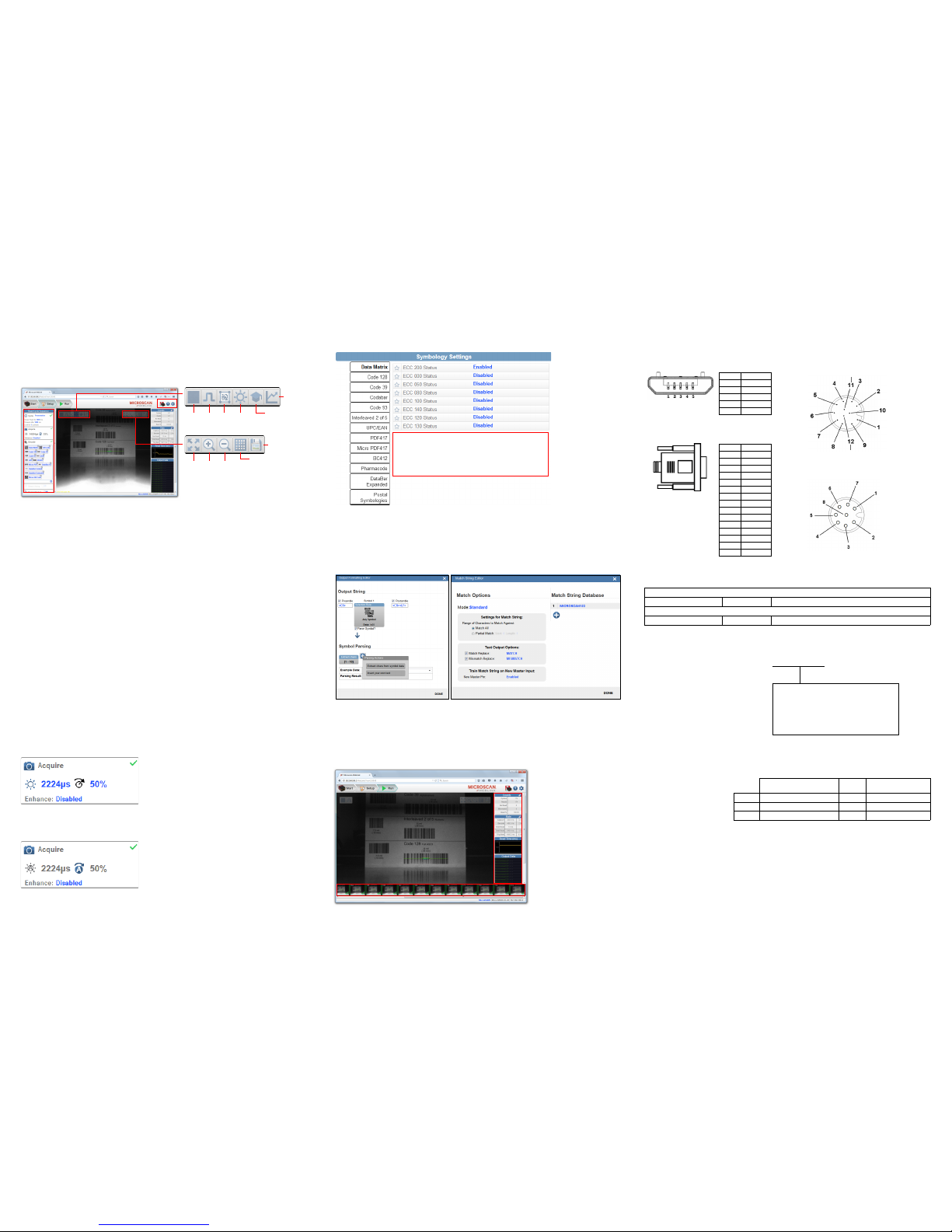
Power Requirements and Pin Assignments
MicroHAWK ID-20: 5VDC ± 5%; 350mA at 5VDC (typ.)
MicroHAWK ID-30: 5V ± 5%; 600mA at 5VDC (typ.)
MicroHAWK ID-40: 4.75V – 30V; 150mA at 24VDC (typ.)
ID-20 Micro-USB Type B Socket Connector
Pin Function
1 Vbus (5V)
2 D–
3 D+
4 N/C
5 Ground
ID-30 15-Pin High-Density Dsub
USB/Serial Socket Connector
ID-40 M12 Connectors
Pin Function
1 +5VDC
2 TX232
3 RX232
4 GND
5 D+
6 N/C
7 Output 1+
8 Default+
9 Trigger+
10 D–
11 Output 3+
12 New Master+
13 Chassis
14 Output 2+
15 Vbus
TX (+)
RX (–)
RX (+)
TX (–)
Terminated
Terminated
M12 8-pin Socket (Ethernet)
Terminated
Term i na t ed
Ground
Output 3
Output 1
Output 2
New Master
Default
Power
Input Common
Output Common
RS-232 (Host) RxD
Trigger
RS-232
(Host) TxD
M12 12-pin Plug
Note: Accessory
cable required
between 15-pin
socket and host
USB port.
Step 12 — Configure Symbology Settings
Clicking the gear icon at the bottom of the Decode dialog brings up Symbology Settings. This allows
you to configure every parameter for every available code type.
Data Matrix error correction parameters are
shown in this example, but you can configure any
parameter for any of the code types supported by
WebLink. All parameter changes for all code types
take effect immediately.
Step 9 — Explore the Setup View
The Setup View allows you to configure all aspects of a setup. The left pane of the UI gives you the
ability to configure Cycle type, Acquire, Decode, Match String, Format Output, and Outputs 1, 2,
and 3 parameters.
Clicking the Save icon in the upper right of the interface saves current settings to the reader’s flash
memory so the settings will be available when the reader is rebooted.
The question mark icon in the upper right of the interface opens WebLink Help.
The gear icon in the upper right of the interface brings up Application Settings.
Start
and
Stop
Trigger
WOI
Auto
Photometry
Optimize
Train
Resize
image to
fit image
area
Zoom
In
Zoom
Out
Show All
Images from
Read Cycle
Save full-size
image
Step 10 — Configure Read Cycle Settings
The Cycle section of the Setup View allows you to modify the trigger, determine the number of symbols
for the reader to expect, and set Read Cycle Timeout. A dropdown menu of various Cycle types provides
a variety of options, each with configurable parameters.
Presentation
This mode, commonly referred to as “hand presentation mode”, uses Continuous Trigger along with
Continuous Capture Mode and a Timeout at End of Read Cycle. Green Flash Mode is set to Static
Presentation and the Green Flash Duration is set to 1 second.
Continuous
This mode allows you to set the Read Cycle Timeout and the expected number of symbols.
Triggered
This mode sets the Read Cycle to Serial Data and Edge, End of Read Cycle is set to Timeout or New
Trigg er, and Capture Mode is set to Rapid Capture with 1 capture. You can adjust the Serial Trigger,
Trigger Delay, Timeout, and Number of Symbols.
Start / Stop
This mode uses External Level with a Read Cycle Timeout and Continuous Capture, allowing you to
set Leading Edge and Trailing Edge as well as the Serial Trigger and the Start and Stop Characters.
Custom
This mode allows you a wider variety of read cycle scenarios. Use this mode to select Tri gger mode and
to set Serial Trigger Character and Trigger Delay; to select Capture Mode and to set Number of
Captures, Rapid Capture Mode, and Delay between Images; and to select the End Cycle On setting
as well as Timeout and Number of Symbols.
Step 11 — Configure Acquire Settings
Acquire settings allow you to set Exposure (signified by the sun icon) and Gain (signified by the dial
and right-pointing arrow icon) in real time. Clicking any of these settings will cause a control to appear,
allowing you to modify that setting. Settings take effect immediately.
When Auto Photometry is enabled instead of Standard, Exposure and Gain are read-only. The A
shown on the sun and dial icons signifies that Auto Photometry is enabled. Auto Photometry constantly
determines the best Exposure and Gain settings during each read cycle.
Standard
Auto Photometry
Step 13 — Format Output and Match String
Format Output, when enabled in the Setup View, allows you to determine the many ways in which
barcode data can be formatted and parsed before it is output as a data string. You can also set Preamble
and Postamble in this dialog.
Match Options and Match String Database, accessible by clicking the Match String section in the
Setup View, allow you to set the match code mode, text output, new master, and match string database.
Step 14 — Run the Application
In the Run view, you can observe the progress of the setup as it follows the parameters you have
defined. The right panel of the UI shows Counts for Cycles, Reads, No Reads, and Mismatches, as
well as Rate information for Capture, Decode, Overhead, Total Read, and Trigger Rate, as well as
Output Data. A "filmstrip" below the image area shows each image capture with a green check mark
for good reads and a red x for no reads.
Example Part Number:
7312-2102-1005
MicroHAWK ID-30, Auto ID, SXGA 1.2
Megapixel, Mono, High Density, 102 mm
Focus Distance, Red Outer LEDs, High
Speed X-Mode Decoder.
Sensor Table
Pixels (H x V) Shutter
Frames per Second
(Standard / High)
WVGA 752 x 480, 0.3 MP, Mono Global 10 fps / 60 fps
SXGA 1280 x 960, 1.2 MP, Mono Global 10 fps / 42 fps
QSXGA 2592 x 1944, 5 MP, Color Rolling 5 fps
 Loading...