

Page 1
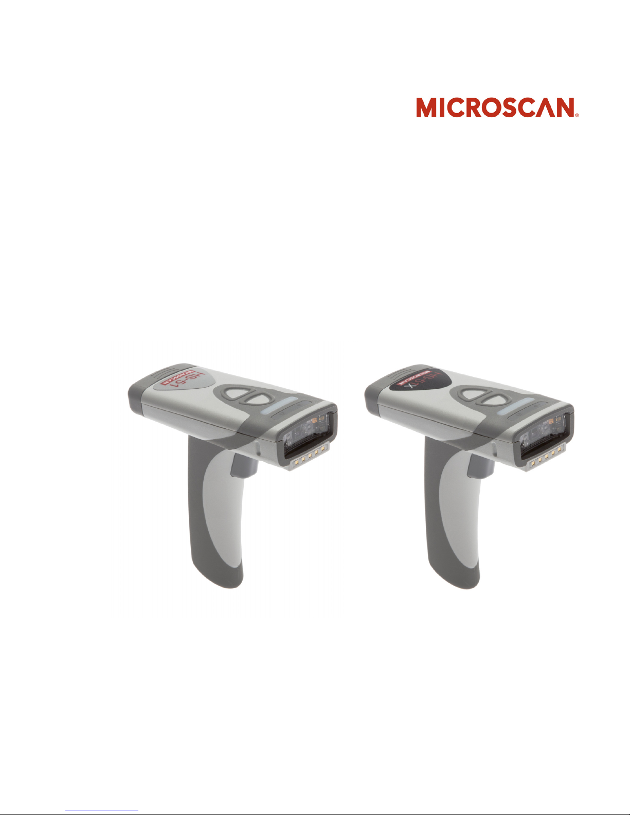
HS-51/HS-51X Wireless
Handheld Reader User Manual
P/N 84-100053 Rev A
Page 2

Copyright and Disclaimer
Copyright ©2014
Microscan Systems, Inc.
Tel: +1.425.226.5700 / 800.762.1149
Fax: +1.425.226.8250
All rights reserved. The information contained herein is proprietary and is provided solely for the purpose
of allowing customers to operate and/or service Microscan manufactured equipment and is not to be
released, reproduced, or used for any other purpose without written permission of Microscan.
Throughout this manual, trademarked names might be used. We state herein that we are using the names
to the benefit of the trademark owner, with no intention of infringement.
Disclaimer
The information and specifications described in this manual are subject to change without notice.
Latest Manual Version
For the latest version of this manual, see the Download Center on our web site at:
www.microscan.com.
Technical Support
For technical support, e-mail: helpdesk@microscan.com.
Warranty
For current warranty information, see: www.microscan.com/warranty.
Microscan Systems, Inc.
United States Corporate Headquarters
+1.425.226.5700 / 800.762.1149
United States Northeast Technology Center
+1.603.598.8400 / 800.468.9503
European Headquarters
+31.172.423360
Asia Pacific Headquarters
+65.6846.1214
ii HS-51/HS-51X Wireless Handheld Reader User Manual
Page 3

Table of Contents
Chapter 1 Quick Start
Check Hardware......................................................................................1-2
Install the Battery.....................................................................................1-3
Charge the Reader .................................................................................. 1-4
Wireless Interface....................................................................................1-5
Install ESP ............................................................................................... 1-6
Select Model............................................................................................ 1-7
Connect to the Reader ............................................................................ 1-8
Configure the Reader .............................................................................. 1-9
Save Changes in ESP ...........................................................................1-10
Chapter 2 Using ESP
App Mode ................................................................................................ 2-2
Tree Controls...........................................................................................2-3
Menu Toolbar .......................................................................................... 2-4
Send/Receive ....................................................................................... 2-14
Chapter 3 Basic Operations
Practice Targeting ................................................................................... 3-2
Dual Optics .............................................................................................. 3-3
Operational Feedback ............................................................................. 3-5
Introduction
Chapter 4 Communications
Communications by ESP......................................................................... 4-2
Communications Overview...................................................................... 4-3
Bluetooth ................................................................................................. 4-4
Batch Mode ............................................................................................. 4-6
Preamble ................................................................................................. 4-9
Postamble..............................................................................................4-10
Preamble and Postamble by ESP ......................................................... 4-11
Keyboard Mapping ................................................................................ 4-12
USB Keyboard Rate .............................................................................. 4-13
Text Command Timeout ........................................................................4-14
Other Communications Mode Commands ............................................ 4-15
Chapter 5 Read Cycle
Read Cycle by ESP ................................................................................. 5-2
Trigger Active .......................................................................................... 5-3
Default Continuous Event........................................................................5-4
Maximum Decodes per Read ..................................................................5-5
Read Cycle Timeout ................................................................................ 5-6
Ignore Duplicate Symbol Timeout ........................................................... 5-7
Targeting Zone Tolerance .......................................................................5-8
HS-51/HS-51X Wireless Handheld Reader User Manual iii
Page 4

Table of Contents
Chapter 6 Symbologies
Morphological Preprocessing .................................................................. 5-9
Camera Settings.................................................................................... 5-10
Symbologies by ESP............................................................................... 6-2
Data Matrix .............................................................................................. 6-3
QR Code ................................................................................................. 6-4
Aztec Code.............................................................................................. 6-5
Code 39................................................................................................... 6-6
Code 128................................................................................................. 6-7
BC412 ..................................................................................................... 6-8
Code 93................................................................................................... 6-9
Codabar................................................................................................. 6-10
Interleaved 2 of 5................................................................................... 6-11
UPC....................................................................................................... 6-12
Postal .................................................................................................... 6-13
Pharmacode .......................................................................................... 6-14
GS1 DataBar ......................................................................................... 6-16
PDF417 ................................................................................................. 6-17
MicroPDF417 ........................................................................................ 6-18
Composite ............................................................................................. 6-19
Symbology Identifier.............................................................................. 6-20
Chapter 7 I/O Parameters
I/O Parameters by ESP........................................................................... 7-2
No Read Notification ............................................................................... 7-3
Targeting ................................................................................................. 7-4
Beep and Vibrate..................................................................................... 7-5
Button Stay-Down Time .......................................................................... 7-6
Button/Trigger Programming ................................................................... 7-7
Data Validation ...................................................................................... 7-10
Chapter 8 Advanced Operations
Continuous Read..................................................................................... 8-2
Mirroring .................................................................................................. 8-3
Bluetooth Keyboard-to-Windows 7 Pairing.............................................. 8-4
Bluetooth Keyboard-to-Table Pairing ...................................................... 8-8
Bluetooth Keyboard-to-Mobile Phone Pairing ....................................... 8-11
Reader Paging ...................................................................................... 8-13
Bluetooth Out-of-Range Notification...................................................... 8-14
Cell Phone Reading Enhancement ....................................................... 8-15
Chapter 9 Terminal
Terminal View.......................................................................................... 9-2
Find ......................................................................................................... 9-3
Send ........................................................................................................ 9-4
iv HS-51/HS-51X Wireless Handheld Reader User Manual
Page 5

Macros..................................................................................................... 9-5
Terminal Right-Click Menu ...................................................................... 9-6
Terminal Dropdown Menu ....................................................................... 9-7
Chapter 10 Utilities
Differences from Default........................................................................10-2
Firmware................................................................................................ 10-3
Bluetooth ............................................................................................... 10-5
Advanced............................................................................................... 10-6
Appendices
Appendix A General Specifications .........................................................A-2
Appendix B Electrical Specifications .......................................................A-5
Appendix C Configuration Symbols.........................................................A-6
Appendix D Communications Protocol ..................................................A-18
Appendix E ASCII Table........................................................................A-19
Appendix F Maintenance.......................................................................A-20
Appendix G Glossary of Terms .............................................................A-21
Introduction
HS-51/HS-51X Wireless Handheld Reader User Manual v
Page 6

About the HS-51 and HS-51X
About the HS-51 and HS-51X
The HS-51 Wireless Handheld 2D Reader is a general-purpose 2D reader. Its many features
include dual field optics for both High Density and Wide Angle, a ruggedized design, and
compact size.
The HS-51X Wireless Handheld DPM Reader is a special-purpose 2D reader for decoding
direct part marks. Microscan’s X-Mode decode algorithms make the HS-51X an ideal
solution for reading difficult marks on many surfaces, including PCBs, electrical components,
castings, and sheet metal. Its tough design makes it a good choice for manufacturing and
light industrial applications.
Both readers can be configured and tested easily using the intuitive tree controls and user
interface of Microscan’s ESP Software.
Note: The HS-51 and HS-51X Wireless Handheld Readers have unique algorithm
licenses, and the HS-51 cannot be field-upgraded to an HS-51X.
About This Manual
This manual provides complete information on setting up, installing, and configuring the
HS-51 and HS-51X Wireless Handheld Readers. The chapters are presented in the order
in which the reader would be assembled, configured, and optimized.
Highlighting
Cross-references and web addresses are highlighted in blue bold.
Bold Initial Caps are used throughout the manual for emphasis.
vi HS-51/HS-51X Wireless Handheld Reader User Manual
Page 7

Introduction
Statement of Agency Compliance
The HS-51 and HS-51X Wireless Handheld Readers have been tested for compliance
with FCC regulations and were found to be compliant with all applicable FCC Rules and
Regulations.
IMPORTANT NOTE: To comply with FCC RF exposure compliance requirements, this
device must not be co-located or operate in conjunction with any other antenna or transmitter.
CAUTION: Changes or modifications not expressly approved by the party responsible for
compliance could void the user’s authority to operate the equipment.
The HS-51 and HS-51X Wireless Handheld Readers have been tested for compliance to
CE (Conformité Européenne) standards and guidelines and were found to conform to
applicable CE standards, specifically the EMC requirements EN 55024, ESD EN 61000-4-2,
Radiated RF Immunity EN 61000-4-3, ENV 50204, EFT EN 61000-4-4, Conducted RF
Immunity EN 61000-4-6, EN 55022, Class B Radiated Emissions, and Class B Conducted
Emissions.
HS-51/HS-51X Wireless Handheld Reader User Manual vii
Page 8

Statement of RoHS Compliance
Statement of RoHS Compliance
All Microscan readers with a ‘G’ suffix in the FIS number are RoHS-Compliant. All compliant
readers were converted prior to March 1, 2007. All standard accessories in the Microscan Product
Pricing Catalog are RoHS-Compliant except 20-500013-01 and 98-000039-02. These products
meet all the requirements of “Directive 2002/95/EC” European Parliament and the Council of
the European Union for RoHS compliance. In accordance with the latest requirements, our
RoHS-Compliant products and packaging do not contain intentionally added Deca-BDE,
Perfluorooctanes
trace levels. To view the document stating these requirements, please visit:
http://eur-lex.europa.eu/LexUriServ/LexUriServ.do?uri=CELEX:32002L0095:EN:HTML
and
http://eur-lex.europa.eu/LexUriServ/LexUriServ.do?uri=OJ:L:2006:372:0032:0034:EN:PDF
Please contact your sales manager for a complete list of Microscan’s RoHS-Compliant products.
This declaration is based upon information obtained from sources which Microscan believes to be reliable, and
from random sample testing; however, the information is provided without any representation of warranty,
expressed or implied, regarding accuracy or correctness. Microscan does not specifically run any analysis on our
raw materials or end product to measure for these substances.
The information provided in this certification notice is correct to the best of Microscan’s knowledge at the date of
publication. This notice is not to be considered a warranty or quality specification. Users are responsible for
determining the applicability of any RoHS legislation or regulations based on their individual use of the product.
In regards to “RoHS Directive 2011_65_EU” Microscan produces Monitoring and Control Instruments as well as
Industrial Monitoring & Control Instruments as defined within the directive. Microscan has developed and is
implementing a RoHS2 compliance plan with the intention of bringing all active products listed in our current
marketing literature within full compliance as per the directive deadlines.
Key milestones for the transition plan are as follows:
• Complete internal product audit by July 2014.
• Initial “Monitoring and Control Instruments” RoHS2 compliant products available by December 2014
• Initial “Industrial Monitoring & Control Instruments” RoHS2 compliant products available by July 2015
• All new products introduced in 2015 are expected to be WEEE & RoHS2 compliant.
Microscan will mark the products with the ‘CE’ marking that complies with the RoHS2 process to acquire ‘CE’ certification
per the example given: Example >> Machinery directive + EMC directive + RoHS2 = Declaration of Conformity.
(PFOS) or Perfluorooctanic Acid (PFOA) compounds above the maximum
viii HS-51/HS-51X Wireless Handheld Reader User Manual
Page 9

1 Quick Start
Check Hardware........................................................................................................................... 1-2
Install the Battery.......................................................................................................................... 1-3
Charge the Reader ....................................................................................................................... 1-4
Configure Hardware ..................................................................................................................... 1-5
Install ESP.................................................................................................................................... 1-6
Select Model................................................................................................................................. 1-7
Connect to the Reader ................................................................................................................. 1-8
Configure the Reader ................................................................................................................... 1-9
Save Changes in ESP................................................................................................................ 1-10
Contents
This section is designed to get your HS-51 Wireless Handheld 2D Reader or HS-51X
Wireless Handheld DPM Reader up and running quickly. Detailed setup information for
configuring reader parameters can be found in subsequent sections.
HS-51/HS-51X Wireless Handheld Reader User Manual 1-1
Page 10
Check Hardware
*Charging Station without Embedded
Modem available as an accessory.
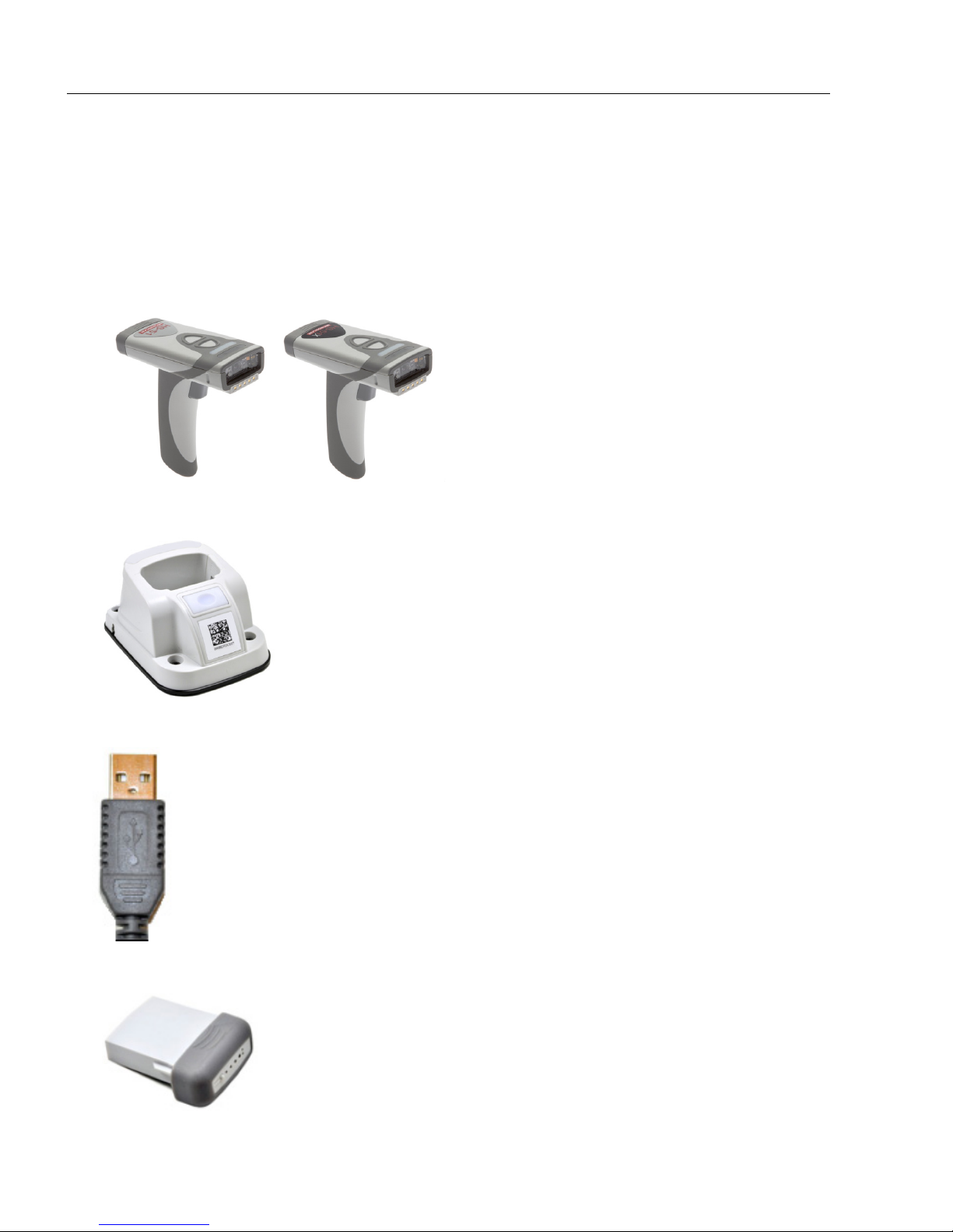
Check Hardware
Hardware for Default Configuration
All required hardware for default configuration is included with the reader and does not
need to be purchased separately. This includes a battery, a charging base with embedded
Bluetooth modem, and a 3-foot USB cable.
• HS-51 Wireless Handheld 2D or HS-51X Wireless Handheld DPM Reader
• Charging Station with Embedded Modem*
•USB Cable
•Battery
1-2 HS-51/HS-51X Wireless Handheld Reader User Manual
Page 11
Quick Start
Push the
battery
into place.
The latch will snap when the battery is fully
in place. Slide the latch to the right and pull
gently to release the battery.
Battery life button
Battery life LEDs
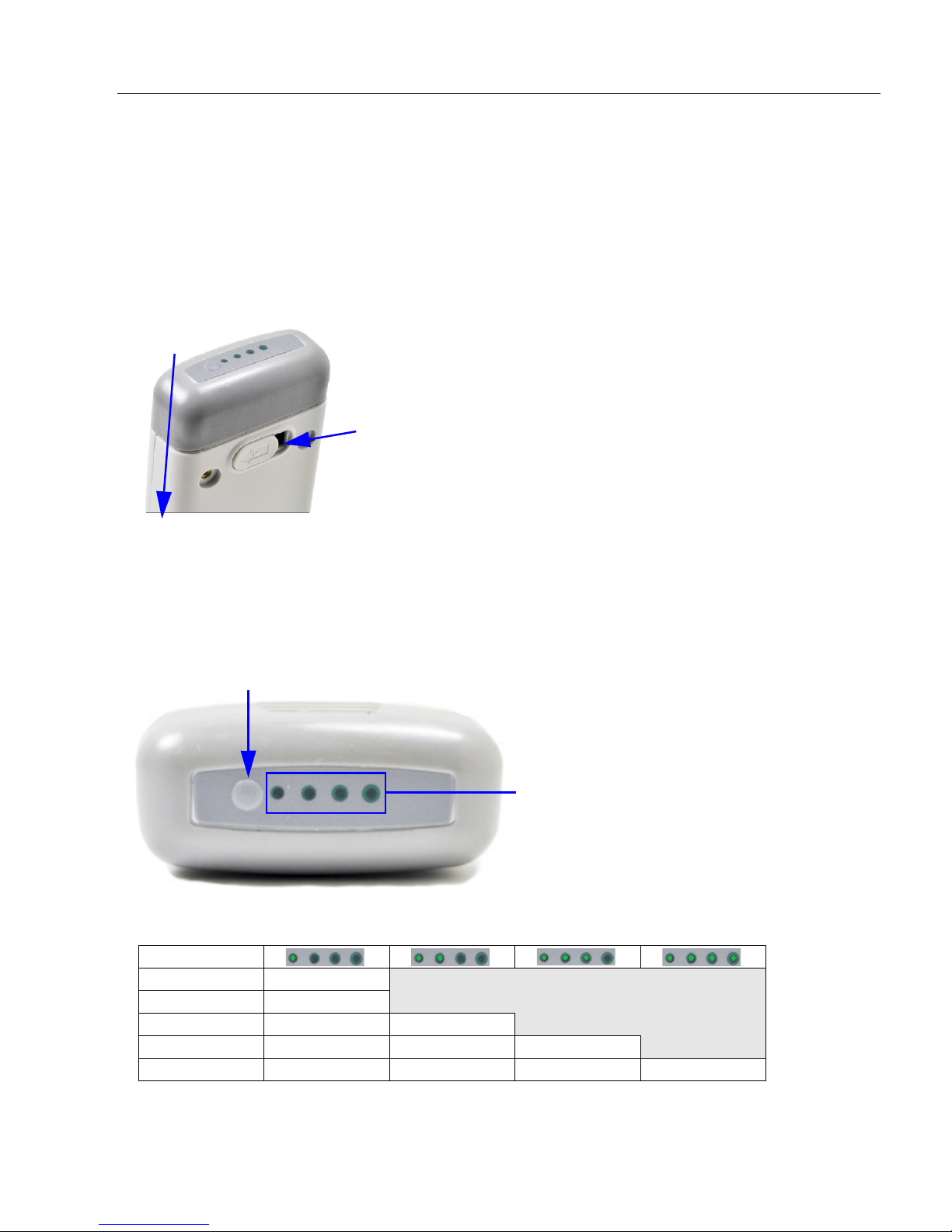
Install the Battery
Battery Installation
Install the battery in the reader as shown below. The latch will snap and the battery will
lock into place.
To remove the battery, slide the latch to the right and then pull gently on the cartridge.
Battery Life LEDs
Press the battery life button to the left of the LEDs to check the amount of battery life
remaining. If the battery has less than 10% capacity, the first LED will flash quickly. If the
battery has greater than 25% capacity, the LEDs will illuminate and remain illuminated for
four seconds.
This table shows battery life LED behavior for different levels of battery life.
Battery Life
<10% Rapid flashing
<25% ON
25-50% ON ON
50-75% ON ON ON
>75% ON ON ON ON
HS-51/HS-51X Wireless Handheld Reader User Manual 1-3
Page 12
Charge the Reader
Charging Station with
Embedded Modem
Charging Station without Embedded
Modem (Accessory Only)
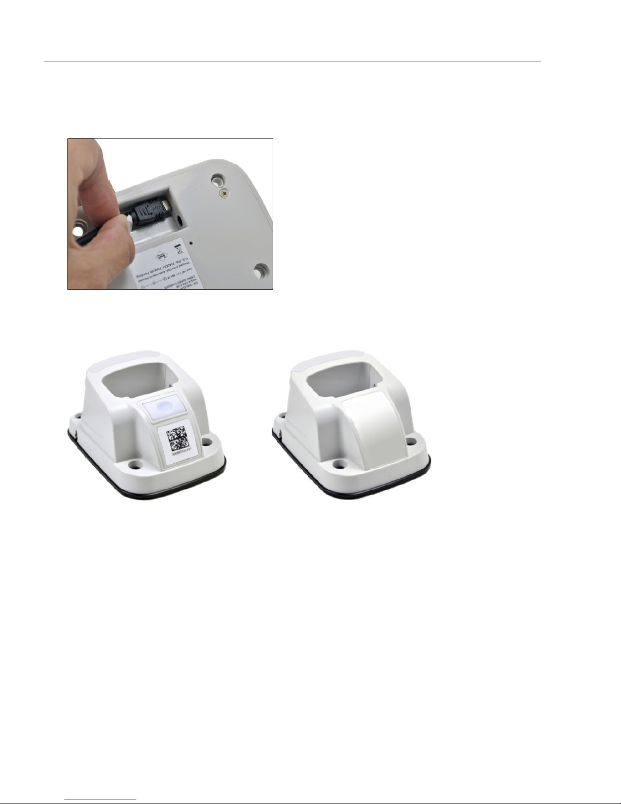
Charge the Reader
• Plug the USB charge cable into the Charging Station’s USB connector.
• Plug the other end of the USB cable into a USB port on your PC.
• Place the reader into the Charging Station. Be sure that the battery has already been
installed in the reader.
Note: Batteries ship with approximately 50% battery life and must be charged to
100% before first use. Approximate time required to charge a depleted battery is four
hours via USB cable.
Power-on the reader once it is charged to 100% by pulling and holding the trigger for
approximately one second. The reader will beep and vibrate and the LEDs will flash to
indicate that it has been powered on.
Note: Pressing and holding the buttons on the top of the reader will also power it on.
1-4 HS-51/HS-51X Wireless Handheld Reader User Manual
Page 13
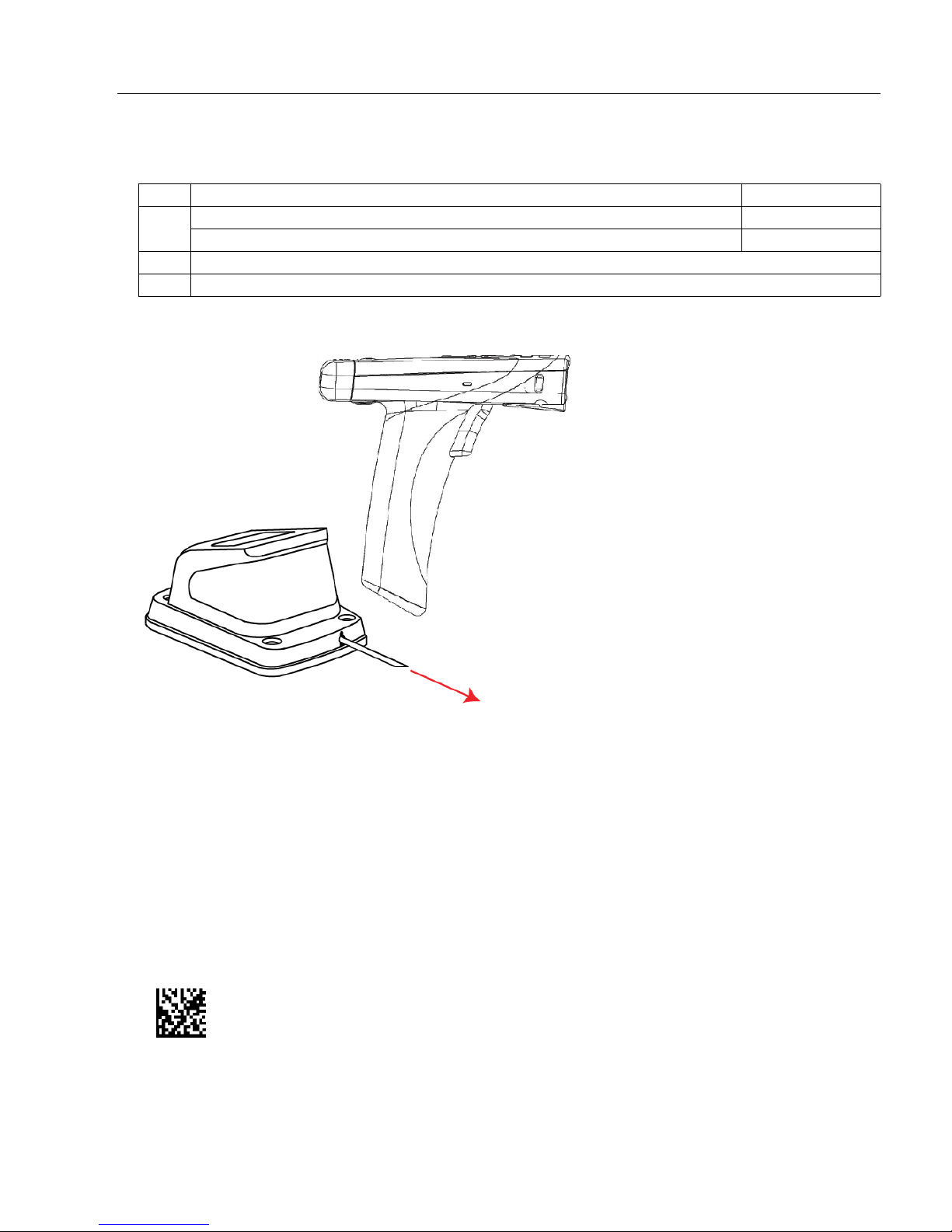
Configure Hardware
Charging Station and Handheld Reader
1
USB Cable
to PC
3
2
Note: All required hardware for default configuration
is included with the reader and does not need to be
purchased separately. This includes a battery, a
charging base with embedded Bluetooth modem,
and a 3-foot USB cable.
Test Symbol
(ABCDEFGHIJKLMNOP)
Item Description Part Number
HS-51 Wireless Handheld 2D Reader FIS-HS51-0001G
1
HS-51X Wireless Handheld DPM Reader FIS-HS51X-0002G
2 Charging Station with Embedded Modem
3 Lithium-Ion Battery
Quick Start
Installation
• Connect the Charging Station with Embedded Modem to the PC via the USB Cable.
•Place the Battery in the reader.
• Charge the reader until the battery LEDs show a 100% charge.
• Power-on the reader.
• Decode the Quick Connect Code on the Charging Station to establish a Bluetooth
connection between the reader and modem.
• Configure the reader for your application in ESP before use.
• Save Settings using ESP when reader configuration is complete.
HS-51/HS-51X Wireless Handheld Reader User Manual 1-5
Page 14
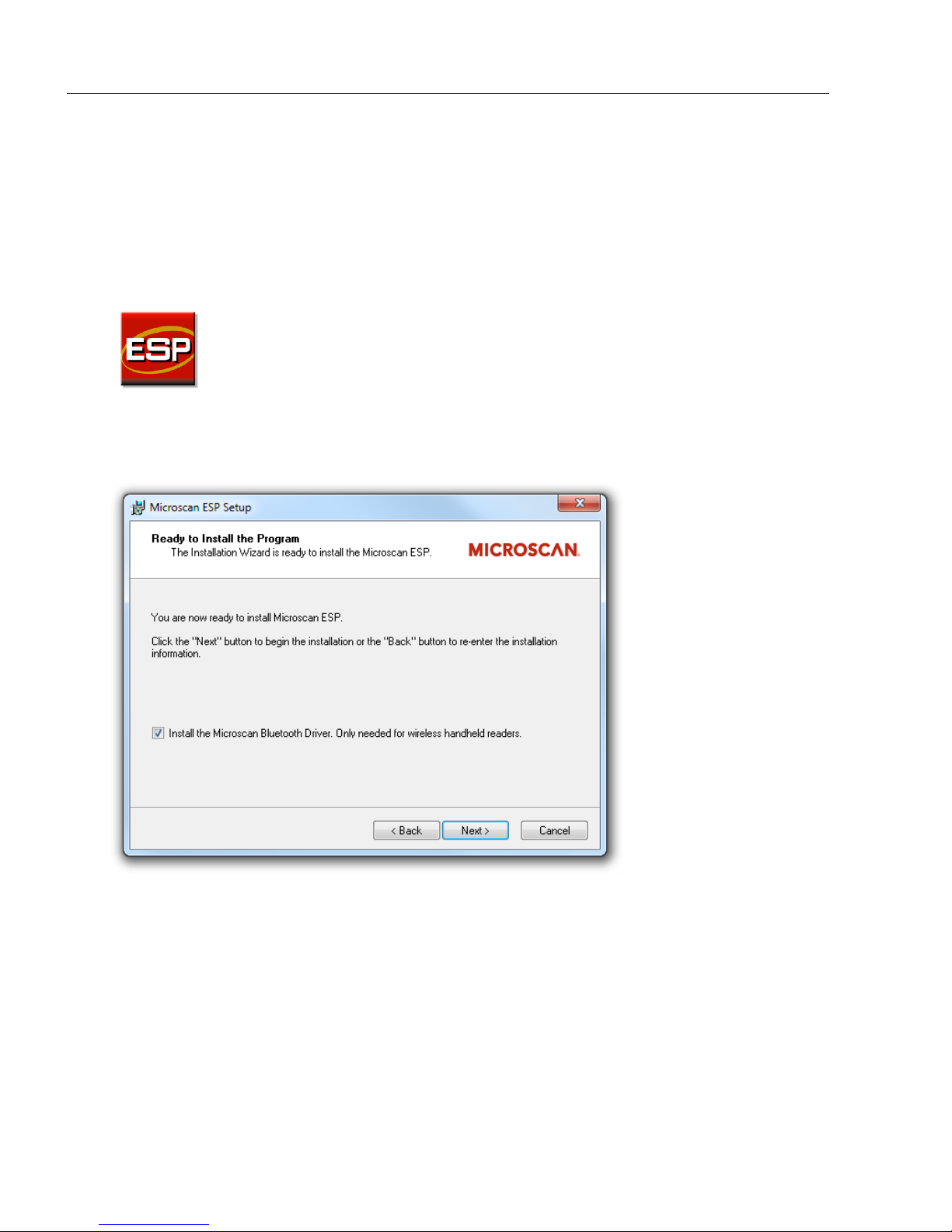
Install ESP
Install ESP
ESP Software is Microscan’s configuration and testing software. Use ESP to set up your
HS-51 or HS-51X Wireless Handheld Reader.
ESP can be found on the
1. Follow the prompts to install ESP from the Tools Drive.
2. Click on the ESP icon to run the program.
Note: ESP can also be installed from the Download Center at www.microscan.com.
Important: If you intend to use the reader’s Bluetooth functionality, click the Install
the Microscan Bluetooth Driver
Microscan Tools Drive
check box when you see this dialog during installation.
that is shipped with the reader upon request.
Minimum System Requirements
• 233 MHz Pentium processor
• Windows 7 (32-bit or 64-bit), Vista (32-bit or 64-bit), or XP (32-bit or 64-bit) operating system
• Internet Explorer 6.0 or higher
• 128 MB RAM or greater
• 160 MB hard drive space
• 800 x 600 minimum 256 color display (1024 x 768 32-bit color recommended)
1-6 HS-51/HS-51X Wireless Handheld Reader User Manual
Page 15
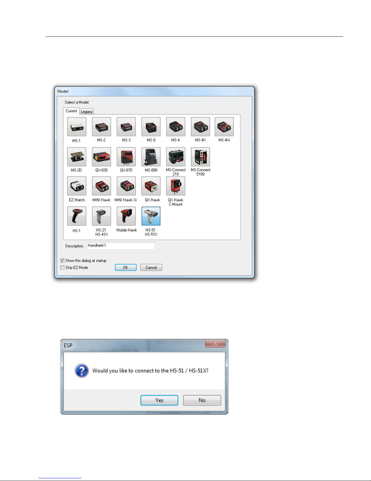
Select Model
When you start ESP, the following menu will appear:
Quick Start
•
Click the HS-51/HS-51X button and then click OK. If you do not want to make this selection
every time you start ESP, uncheck “Show this dialog at startup”. If you need to select
another model later, click the Switch Model button at the top of the screen.
Note: You can also type a name of your choice in the Description text field and click OK.
• Click Yes when this dialog appears:
HS-51/HS-51X Wireless Handheld Reader User Manual 1-7
Page 16
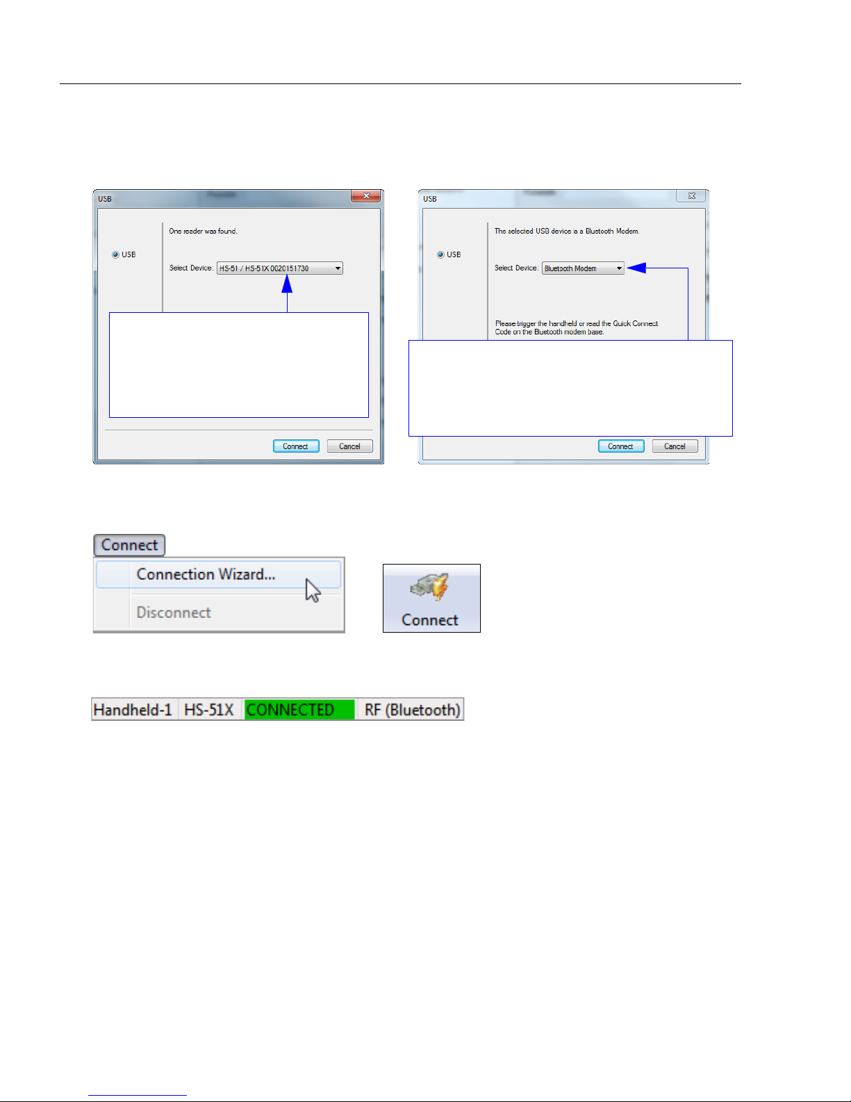
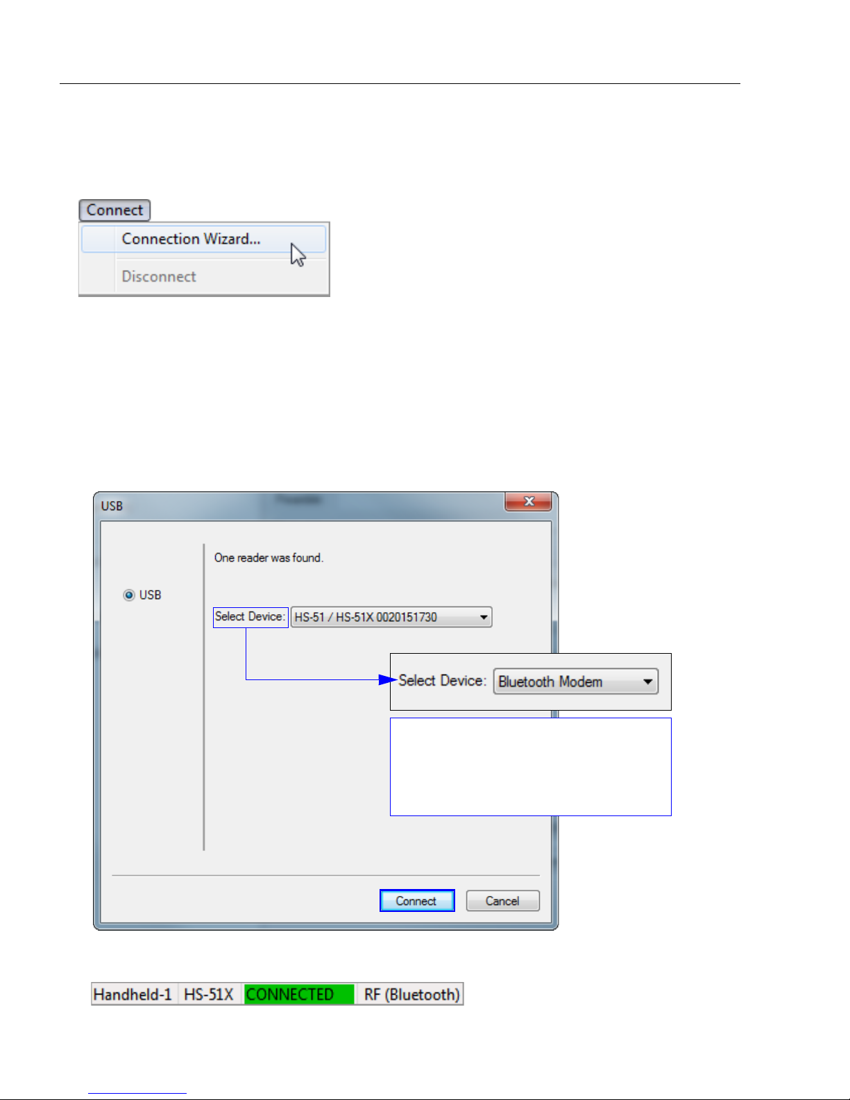
Connect to the Reader
If the reader is already connected to
the Bluetooth Modem, you will see
the ID of your reader in the Select
Device field. The reader ID number
should match the serial number
printed on the reader’s ID label.
If the reader is not yet connected to the modem,
the Select Device field will show Bluetooth
Modem. Decode the Quick Connect Code on
the base of the modem to connect the reader to
the modem. The reader ID will then appear.
or
Connect to the Reader
•
The
USB
dialog will appear. You will see the device ID in the
Note: You can also select Connection Wizard from the Connect dropdown menu or
click the Connect button to access the USB dialog.
Select Device
field. Click
Connect
.
• When you are connected successfully, the CONNECTED message will appear in a
green box in the status bar at the bottom right of the screen.
You are now ready to configure your reader using ESP. Subsequent sections provide
more detailed information about ESP’s configuration options.
1-8 HS-51/HS-51X Wireless Handheld Reader User Manual
Page 17
Configure the Reader
Quick Start
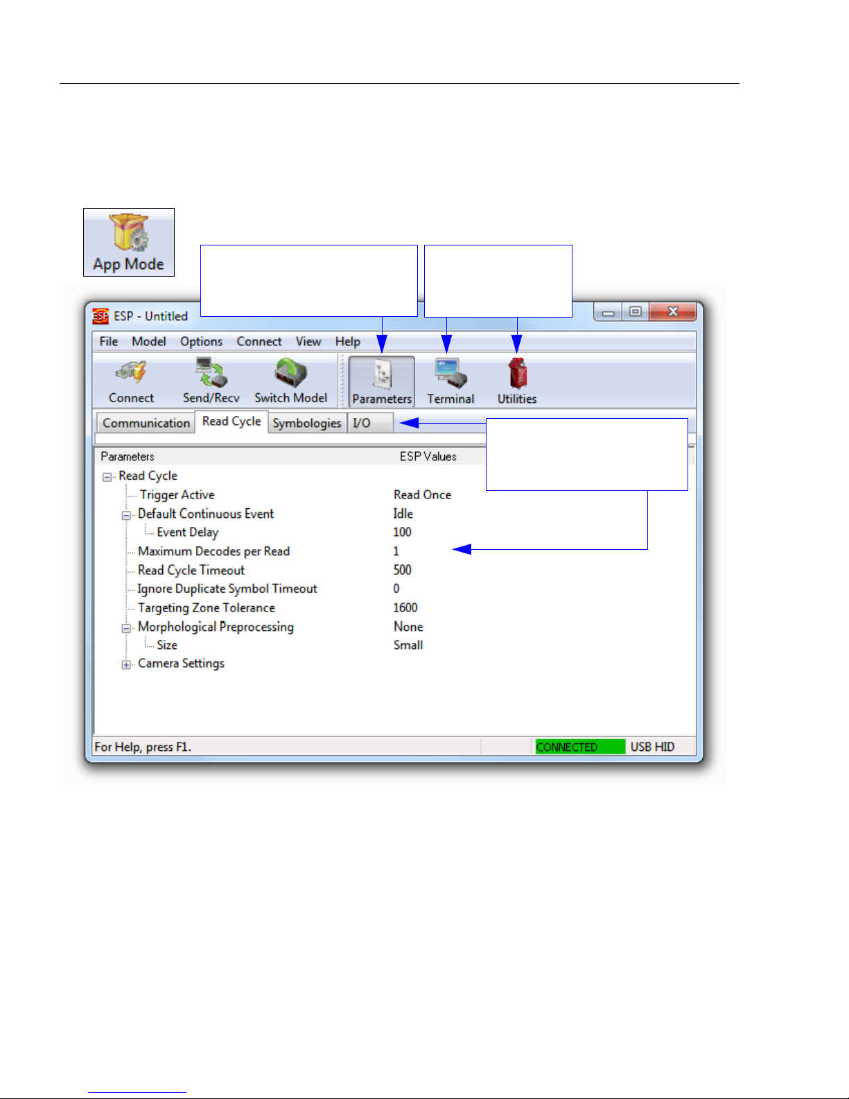
The following modes are accessible by clicking the buttons in the first row of
• Click the Connect button to establish communication.
• Click the Send/Recv button to send or receive commands.
• Click the Switch Model button to open the model menu, or to return to a previous model.
• Click the Parameters button to show the tabbed tree controls for Communication, Read
Cycle, Symbologies, and I/O Parameters.
• Click the Term inal button to display decoded symbol data and to send serial commands
to the reader using text or macros.
• Click the Utilities button to show the tabbed interfaces for Differences from Default,
Firmware, Bluetooth, and Advanced settings.
For further details, see ESP Help in the dropdown Help menu.
App Mode
icons:
HS-51/HS-51X Wireless Handheld Reader User Manual 1-9
Page 18
Save Changes in ESP
1. Left-click on the +
to expand the
desired tree.
2. Double-click on the
desired parameter
and click once in the
selection box to view
options.
5. Right-click on the open
screen and select Save to
Reader to implement the
command in the reader.
4. Left-click again on the
open screen to complete
your selection.
3. Place your cursor in the
selection box, scroll down to
the setting you want to
change, and click once on
the setting.
Save Changes in ESP
To make changes to a configuration setting:
Saving Options
• Send, No Save. Changes will be lost when power is re-applied to the reader.
• Send and Save. This activates all changes in current memory and saves to the reader
for power-on.
1-10 HS-51/HS-51X Wireless Handheld Reader User Manual
Page 19

2 Using ESP
App Mode ..................................................................................................................................... 2-2
Tree Controls................................................................................................................................ 2-3
Menu Toolbar ............................................................................................................................... 2-4
Send/Receive ............................................................................................................................ 2-14
Contents
This section is designed to help you understand the ESP interface.
Enter
a Terminal interface, and a Utilities interface.
ESP can be used to configure the HS-51 and HS-51X Wireless Handheld Readers in the
following ways:
• Tree Controls: Each tree control contains a list of all commands that pertain to that
• Graphic User Interfaces: Settings can be configured using point-and-click tools – radio
• Terminal: ESP’s Terminal allows you to send configuration and utility commands
App Mode
specific category of reader operation. For example, the Communications menu shows
a Communications Mode command which contains a dropdown menu showing the
available communications modes.
buttons, spin boxes, check boxes, and drag-and-drop functions.
directly to the reader by typing them in the Send text field.
to access
Communications, Read Cycle, Symbologies, I/O Parameters,
HS-51/HS-51X Wireless Handheld Reader User Manual 2-1
Page 20
App Mode
Click on tabs in this row to
access configuration trees
like the one shown here.
Click here to open
the Terminal or
Utilities views.
Click the Parameters icon to
return to full App Mode view
from Terminal or Utilities.
App Mode
Click the App Mode button to access specific configuration menus, Utilities tools, and a
Terminal window where serial commands can be entered.
Note: See the corresponding sections of this documentation for specific information on
any of the views or modes mentioned above.
2-2 HS-51/HS-51X Wireless Handheld Reader User Manual
Page 21
Tree Controls
2. Double click on
the parameter and
click once in the
selection box to
view options.
3. Place your cursor
in the selection
box, scroll down to
the setting you
want to change
and click once on
the setting.
4. Left click again on the open screen to complete the
selection.
5. Right click on the open screen and select Save to
Reader to implement the command in the reader.
1. Left click on the +/-
to expand or collapse
the tree.
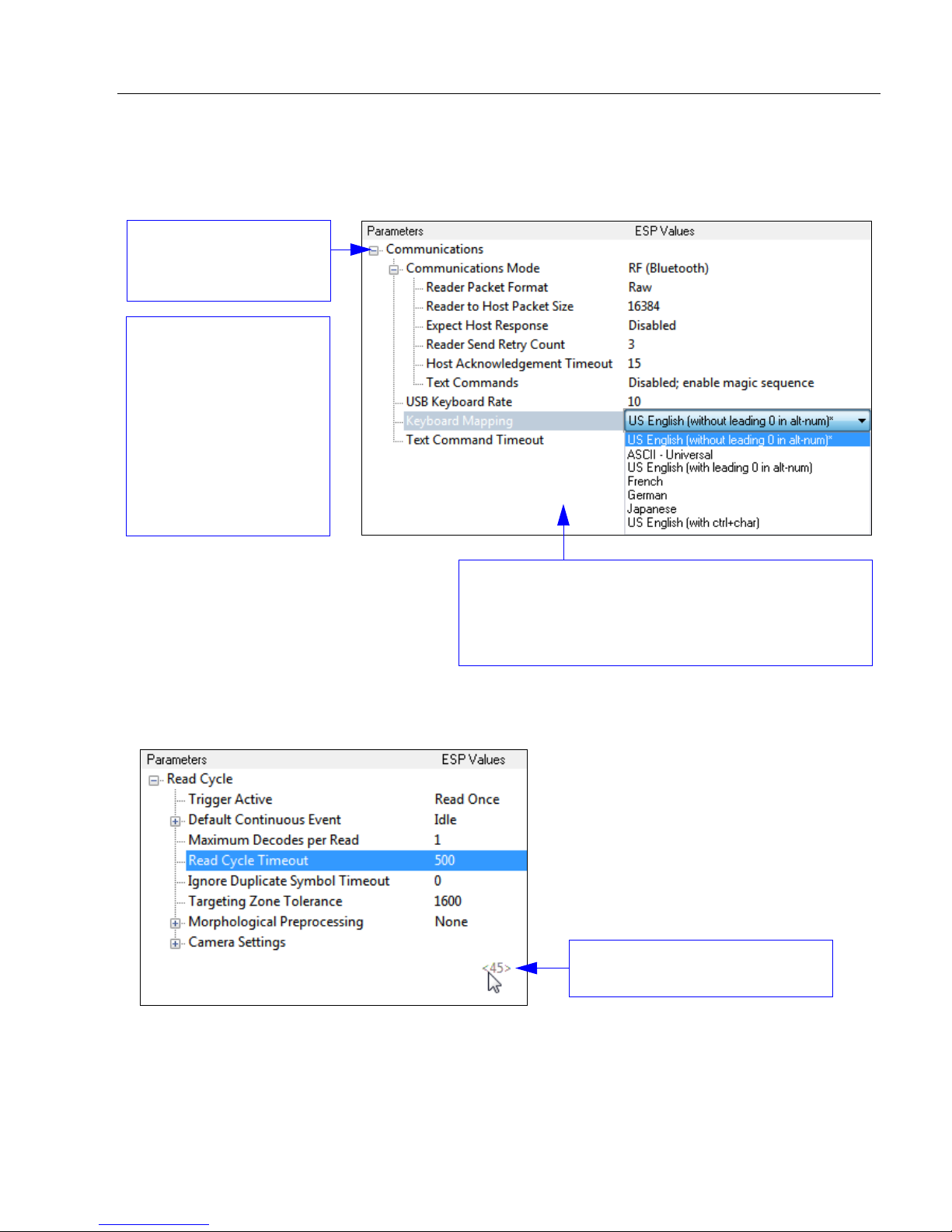
In this example, the command for
Read Cycle Timeout is shown.
To make changes to configuration settings in the tree control menus:
Using ESP
Hint: To see the underlying serial command that corresponds with each tree control item,
click on the item in the tree control and drag the mouse to the open screen. The command
will be displayed between angle brackets.
HS-51/HS-51X Wireless Handheld Reader User Manual 2-3
Page 22
Menu Toolbar
(Save to Reader)
(Receive Reader
Settings)
Menu Toolbar
File > New
Whenever New is selected from the File menu, the
default configuration of ESP is loaded.
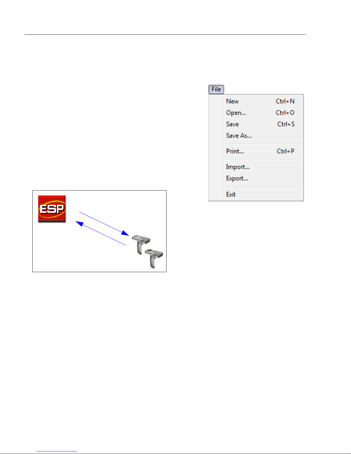
Open / Save
When
is saved to the host computer’s hard drive and available
whenever the same file is selected under Open.
When you save menu changes to your hard drive, these
changes are not saved to your reader. The diagram
below shows how settings can be saved and received
between ESP and the reader, and ESP and the host
hard drive.
Save
or
Save As
is selected, the
ESP
configuration
Import / Export
Import converts the ASCII settings from a text file to ESP configuration settings.
Export converts the active ESP configuration settings to an ASCII text file.
2-4 HS-51/HS-51X Wireless Handheld Reader User Manual
Page 23
Using ESP
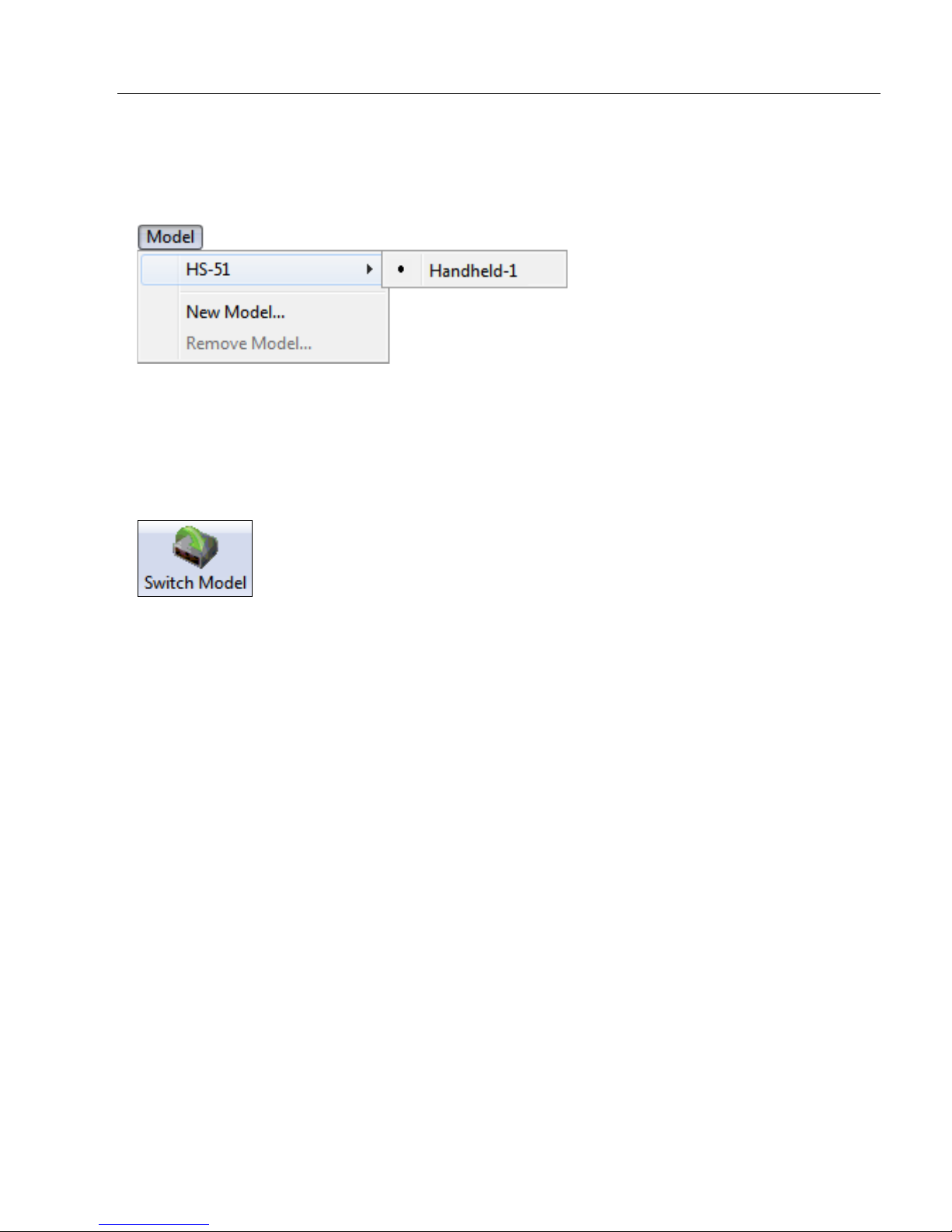
Model
The Model menu allows you to select between reader models. When you choose another
model, the current connection with your present model will be terminated.
New Model
To connect to another model, select New Model, choose the model you want, and click OK.
All models you have selected and enabled will continue to appear in the dropdown model
menu. The New Model option is repeated when you click the Switch Model button on the
top row of icons.
HS-51/HS-51X Wireless Handheld Reader User Manual 2-5
Page 24
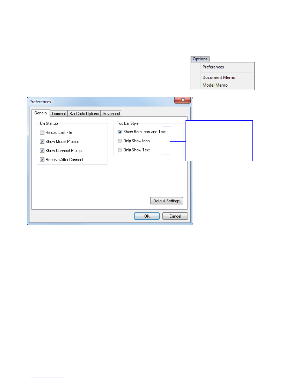
Menu Toolbar
The Toolbar Style
options allow you to
determine how ESP will
display the mode options
in the two rows at the top
of the screen.
Options
You can use the
preferences.
Preferences will be saved and loaded into
opened, whether or not you save the
Options
menu to save memos and set up
ESP
Preferences > General Tab
ESP
ESP
the next time
file to the host computer.
ESP
is
Reload Last File
At startup, reloads the last file saved to the computer.
Show Model Prompt
At startup, remembers the last connected model and displays it in the Connecting...
dialog whenever you attempt to connect.
Show Connect Prompt
At startup, displays the Would you like to connect... prompt.
Receive After Connect
At startup, loads the reader’s settings into ESP. (This is not recommended if you want to
preserve your ESP settings for future use.)
2-6 HS-51/HS-51X Wireless Handheld Reader User Manual
Page 25
Using ESP
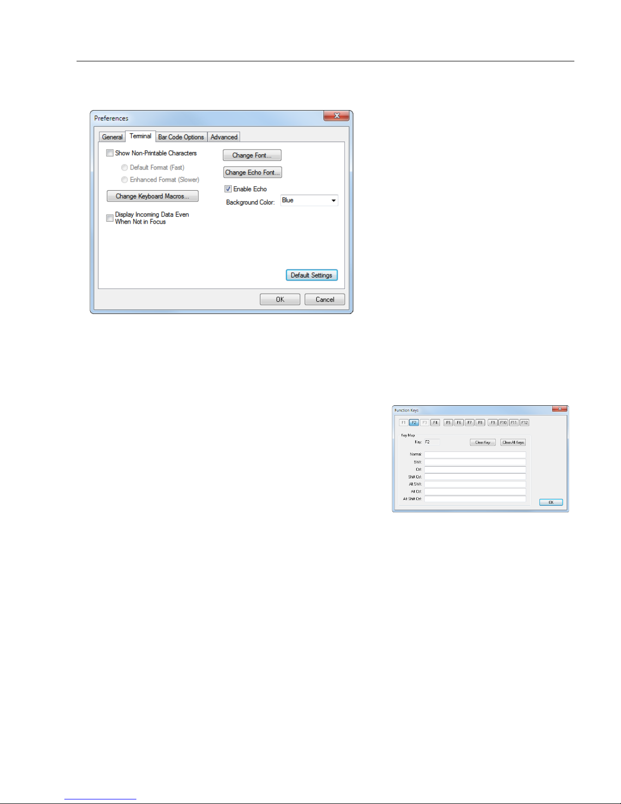
Preferences > Terminal Tab
Show Non-Printable Characters
When Show Non-Printable Characters is enabled, characters such as “CRLF” will be
displayed in the Terminal window. When Enhanced Format is checked, the characters
are displayed with more detailed formatting.
Change Keyboard Macros
Clicking the Change Keyboard Macros button brings
up the Function Keys dialog. In this dialog you can
select the desired function key and then enter your
macro keystrokes in the associated key map. For
example, to make Ctrl-F2 the keystroke to send a trigger
character, select F2, then in the Ctrl row, enter <trigger
character> and click OK. Then whenever the Ctrl-F2
keystroke is pressed, the trigger character will start the
read cycle.
Note: The F1 key is reserved for opening ESP Help and the F3 key is reserved for the
Find Next function.
Change Font
Allows you to modify the font used for decode data received from the reader on the Terminal
screen.
Change Echo Font
Allows you to modify the font used for command characters typed into the Terminal view.
Enable Echo
Allows you to enter command characters in Terminal.
Display Incoming Data Even When Not in Focus
When Display Incoming Data Even When Not in Focus is enabled, data from the reader
will continue to appear in the Terminal even when ESP is not the top window.
HS-51/HS-51X Wireless Handheld Reader User Manual 2-7
Page 26
Menu Toolbar
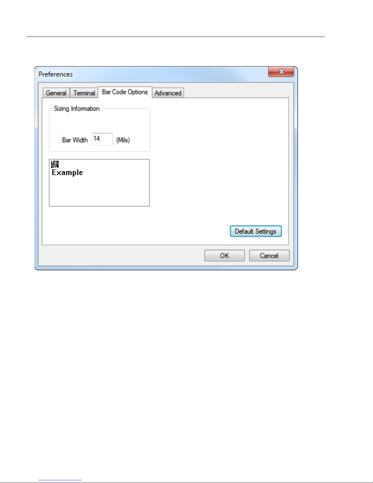
Preferences > Bar Code Options Tab
The Bar Code Options dialog allows you to set the size of user-created symbols.
Sizing Information
Sets the bar width or module width (in mils, or thousandths of an inch) of user-created
symbols.
Example: A bar width of 14 is 0.014 inches.
2-8 HS-51/HS-51X Wireless Handheld Reader User Manual
Page 27
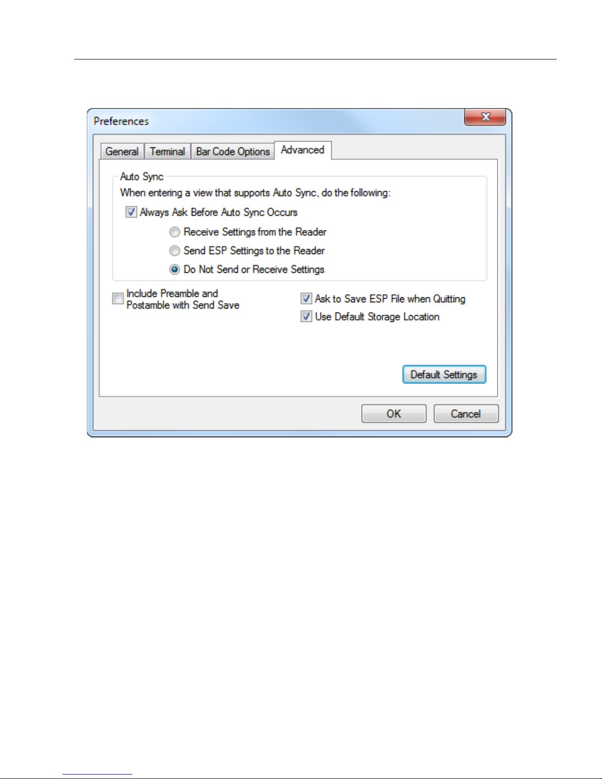
Preferences > Advanced Tab
Using ESP
The Auto Sync options at the top of the Advanced tab allow the user to determine
whether Auto Sync will be enabled automatically in sections of ESP where it is used, or if it
will ask before it enables Auto Sync functions.
Always Ask Before Auto Sync Occurs
If this option box is checked, specific Auto Sync functions can be enabled.
from the Reader will automatically send the reader’s settings to ESP when Auto Sync is
enabled.
settings chosen in
in which Auto Sync will not automatically send reader settings to
to the reader.
Send ESP Settings to the Reader
ESP
to the reader.
Do Not Send or Receive Settings
will automatically send all reader configuration
ESP
Receive Settings
creates a condition
, or send
ESP
settings
Include Preamble and Postamble with Send Save
When this option box is checked, the user-configured Preamble and Postamble characters
will be sent along with other parameters.
HS-51/HS-51X Wireless Handheld Reader User Manual 2-9
Page 28
Menu Toolbar
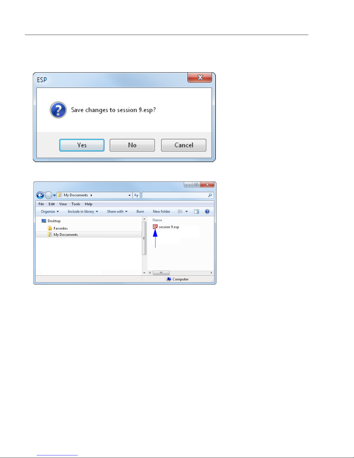
Ask to Save ESP File when Quitting
When enabled, prompts the user to save a .esp file when ending a session.
The .esp file will be saved in the location of your choice.
Use Default Storage Location
When enabled, automatically stores data in ESP’s Application Data folder.
2-10 HS-51/HS-51X Wireless Handheld Reader User Manual
Page 29
Using ESP
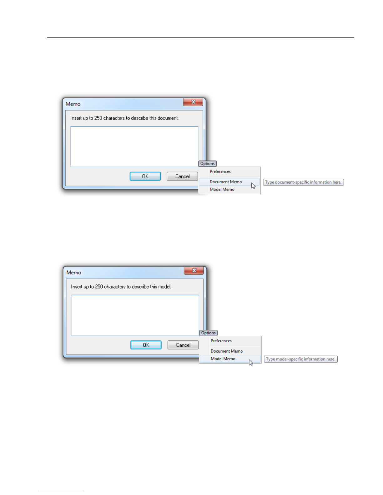
Document Memo
The information you type in the Document Memo field will appear in a context-sensitive text
box whenever your cursor hovers over the Document Memo item on the Options menu.
Model Memo
Similar to Document Memo, the information you type in the Model Memo field will appear
in a context-sensitive text box whenever your cursor hovers over the Model Memo item on
the Options menu. Memos created in Model Memo are specific to the model enabled
when the message was created.
Note:
Memos must be saved in a
If you do not save your current session, any memos that you have entered during the session
will be discarded, and will be unavailable in your next session.
HS-51/HS-51X Wireless Handheld Reader User Manual 2-11
.esp
file if you want them to available in your next session.
Page 30
Menu Toolbar
Bluetooth Modem will appear in the
Select Device field if there is not a
connection between the reader and
modem. Decode the Quick Connect
Code to establish a connection.
Connect
The Connect dropdown menu allows you to access the Connection Wizard, and also to
Disconnect ESP from the reader.
Connection Wizard
To connect using the Connection Wizard:
• Click Connect on ESP’s menu toolbar, and then select Connection Wizard.
• Click
Connect
when you see the reader’s name and serial number in the
Select Device
Note: If the reader is not yet connected to the modem, the Select Device field will show
Bluetooth Modem as the device instead of the reader. Decode the Quick Connect Code
on the base of the modem to connect the reader to the modem. The reader ID will then
appear. Click Connect to continue.
field.
• When a connection is established, the green indicator in the status bar at the bottom
right of the screen will be visible.
2-12 HS-51/HS-51X Wireless Handheld Reader User Manual
Page 31

View
Drag specific configuration
values from the control tree
directly into this field to
encode new symbols.
Choose a spatial
orientation for the
new symbol.
Create a caption
for the symbol
that matches or
describes the
encoded data.
The symbol will be
displayed in the field
at the bottom of the
Bar Code Dialog.
The View menu allows the user to move quickly between the
Parameters, Terminal, and Utilities interfaces without using
the icon buttons on the App Mode toolbar. It also allows the
user to access the Bar Code Dialog, shown below.
Bar Code Dialog
Using ESP
Symbols can be created in the Bar Code Dialog by typing the
useful tool for creating configuration
reading the user-created symbols.
text to be encoded. This is a
symbols, allowing the user to configure the reader by
HS-51/HS-51X Wireless Handheld Reader User Manual 2-13
Page 32

Send/Receive
Send/Receive
To access Receive, Save, Lock, Default, and Advanced options, click the Send/Recv
button or right-click in the tree control areas.
You can also access these options by right-clicking in any of the configuration views.
Receive Reader Settings
From the Send/Recv menu, select Receive Reader Settings.
This option is useful if you want to receive the reader’s settings and save them as a file for
later retrieval. For example, if your reader has settings that you do not want to change,
choosing Receive Reader Settings will allow you to load those settings to ESP and save
them as an ESP file.
Receiving the reader’s settings also assures that you will not subsequently save any
unwanted configuration changes previously made in ESP.
Select this option if you want to upload the reader’s settings to ESP. For example, if your
ESP file has a number of custom settings that you want to maintain and download to the
reader, you will lose those ESP settings if you choose to receive settings from the reader.
Save to Reader
Send, No Save
This saves ESP settings to current memory.
Send and Save
This activates all changes in current memory and saves to the reader.
Lock Reader
This locks in the most recently sent and saved configuration to the reader.
2-14 HS-51/HS-51X Wireless Handheld Reader User Manual
Page 33

Using ESP
Default Current Menu Settings
This option returns the settings in the current tree control to their defaults.
Important: When you select Default Current Menu Settings you are only defaulting
settings in ESP. The reader is not affected unless you download new settings.
Default all ESP Settings
This option returns all settings in ESP to their defaults.
Important: When you select Default all ESP Settings you are only defaulting settings in
ESP. The reader is not affected unless you download new settings.
Advanced Options
Send Current View
This is the same as Save to Reader > Send, No Save except that only the commands in
the current tree control are sent.
Send Current Command
This is the same as Send Current View except that it only saves the command that is
currently selected.
HS-51/HS-51X Wireless Handheld Reader User Manual 2-15
Page 34

Send/Receive
2-16 HS-51/HS-51X Wireless Handheld Reader User Manual
Page 35

3 Basic Operations
Practice Targeting ........................................................................................................................ 3-2
Dual Optics................................................................................................................................... 3-3
Operational Feedback .................................................................................................................. 3-5
Contents
This section explains how to practice targeting and triggering, and also describes the
reader’s Dual Optics and Operational Feedback behaviors.
HS-51/HS-51X Wireless Handheld Reader User Manual 3-1
Page 36

Practice Targeting
When the reader is closer to the symbol, you will see
two separate bars. As you draw the reader away from
the symbol, the two bars converge.
ABCDEFGHIJKLMNOP
Practice Targeting
When first connecting, allow approximately 3 seconds for the reader to initialize.
1. Hold the reader steady and point it at a test symbol.
2. Squeeze and hold the trigger.
3.
Move the reader toward or away from the symbol in a fluid motion until the two side-by-side
blue bars converge in the middle of the symbol. When the reader is at the optimal distance
(about 4 inches or 10 cm), it will decode the symbol and will beep and vibrate while
emitting a green LED flash to indicate a Good Read. At this optimal distance, the two
blue bars should just be touching. Note that the bars overlap as you continue to draw
the reader away from the symbol.
4. If no decode occurs, slowly draw away from or move closer to the symbol while holding
the blue bars centered steadily on the symbol.
Test Symbol
Targeting Suggestions
• Typically, you should not hold the reader exactly perpendicular to the symbol. Position
the reader at an angle to avoid specular reflection.
• Use smooth, fluid motion when targeting the symbol. Do not wave the reader side-to-side
or up-and-down, or attempt to sweep across a symbol, as sudden movements will create
blurred images.
• The reader is omnidirectional and can decode symbols in any orientation. When decoding
1D symbols, be sure that the entire symbol falls well within the field of view.
3-2 HS-51/HS-51X Wireless Handheld Reader User Manual
Page 37

Basic Operations
Wide Angle
High Density
960
640
640
(1280)
Field of View: 30° horiz. by 20° vert.
Focal Point: Approximately 100 mm
Field of View: 50° horiz. by 33.5° vert.
Focal Point: Approximately 115 mm
Dual Optics
The reader’s dual field optical system can read small 2D symbols as well as larger 1D
symbols. An image is captured from each field. The decoder first operates on the image
(High Density or Wide Angle) which was successfully decoded on the last cycle. If unsuccessful,
the next image is decoded.
Move the reader closer to decode smaller symbols and farther away to decode larger symbols.
Imaging Area
The reader’s
optics are divided into High Density and Wide Angle decode zones. Each
decode zone is 960 x 640 pixels.
HS-51/HS-51X Wireless Handheld Reader User Manual 3-3
Page 38

Dual Optics
20 mil Data Matrix
5 mil Code 39
Dual Field
Wide Angle
High Density
Dual Field
Wide Angle
High Density
Dual Optics Examples
3-4 HS-51/HS-51X Wireless Handheld Reader User Manual
Page 39

Basic Operations
Operational Feedback
Condition Reader LEDs Sound Vibration
Successful Power-Up All LEDs flash 1 Beep Handle vibrates
Successful Connection to Host Wireless icon flashes 1 Beep Handle vibrates
Successful Decode and Data Transfer
Successful Decode and Processing of
Configuration Symbol
Batch Mode Enabled, Data Stored Storage icon flashes No sound No vibration
Batch Memory Full
Batch Mode Enabled, No Data Stored Storage icon off No sound No vibration
No Bluetooth Connection No change 4 Beeps No vibration
Bluetooth Connection Established –
Quick Connect Code Scanned
Bluetooth Connection Established –
Battery Removed and Replaced,
Trigger Pulled
Data Being Stored Storage icon flashes No sound No vibration
Good Read indicator
flashes
Good Read indicator
flashes
Storage icon flashes 5
times per second
Wireless icon flashes,
then remains illuminated 1 Beep Handle vibrates
Wireless icon flashes,
then remains illuminated
1 Beep Handle vibrates
2 Beeps Handle vibrates
No sound No vibration
No sound No vibration
HS-51/HS-51X Wireless Handheld Reader User Manual 3-5
Page 40

Operational Feedback
3-6 HS-51/HS-51X Wireless Handheld Reader User Manual
Page 41

Contents
Communications by ESP.............................................................................................................. 4-2
Communications Overview........................................................................................................... 4-3
Bluetooth ...................................................................................................................................... 4-4
Batch Mode .................................................................................................................................. 4-6
Preamble ...................................................................................................................................... 4-9
Postamble................................................................................................................................... 4-10
Preamble and Postamble by ESP .............................................................................................. 4-11
Keyboard Mapping ..................................................................................................................... 4-12
USB Keyboard Rate ................................................................................................................... 4-13
Text Command Timeout............................................................................................................. 4-14
Other Communications Mode Commands ................................................................................. 4-15
4 Communications
This section explains how to set up communications between the reader and a host.
ESP
can be used to configure reader parameters and then to send and save those parameters
to the reader.
You can also configure reader parameters by decoding the Data Matrix symbols in this section.
HS-51/HS-51X Wireless Handheld Reader User Manual 4-1
Page 42

Communications by ESP
Click this button to
bring up the App Mode
view, then click the
Communication tab.
To open nested options,
single-click the +.
To change a setting,
double-click the
setting and use your
cursor to scroll
through the options.
Communications by ESP
4-2 HS-51/HS-51X Wireless Handheld Reader User Manual
Page 43

Communications
Communications Overview
The reader’s default communications mode is RF (Bluetooth).
RF (Bluetooth)
RF (Bluetooth) enables wireless two-way communication between the reader and the
Charging Station with Embedded Modem and allows you to decode symbols. The reader
must be in this mode to communicate with ESP.
USB Native (HID)
USB Native (HID)
must move the switch on the Charging Station with Embedded Modem to the
the left, opposite the direction of the arrow on the switch). This mode of communication is
useful when the reader is storing decoded symbol data and will send the data to the PC when
placed in the Charging Station with Embedded Modem. It is not possible to connect to ESP in
this mode.
allows the reader to communicate with the PC via a wired connection. You
OFF
position (to
USB Keyboard
USB Keyboard causes the reader to appear to the PC as a keyboard. You must move
the switch on the Charging Station with Embedded Modem to the OFF position (to the left,
opposite the direction of the arrow on the switch). This mode allows ASCII characters to
be transmitted as keyboard sequences. It is not possible to connect to ESP in this mode.
HS-51/HS-51X Wireless Handheld Reader User Manual 4-3
Page 44

Bluetooth
Quick Connect Code
Wireless
Icon
Storage Icon
Good Read
Indicator
Bluetooth
Decode the Quick Connect Code located on the front of the Charging Station with embedded
modem to establish Bluetooth communication.
Important: Slide the communication mode switch on the Charging Station to Bluetooth
Mode (the direction of the arrow on the switch) before decoding the Quick Connect Code.
Sliding the mode switch in the other direction enables USB cabled and USB Virtual COM
1-Way Mode operation.
4-4 HS-51/HS-51X Wireless Handheld Reader User Manual
The wireless icon located at the top of the reader will flash as it attempts to make a connection.
The blue LED on the Charging Station will also flash as it attempts to connect. The blue
LED will turn on when the connection is established, the reader will beep once, and the
wireless icon will turn on and remain illuminated.
Page 45

Communications
Important: If you are using a non-Microscan Bluetooth device:
To connect to a non-Microscan Bluetooth device, you will need the Bluetooth address of
that device. The 12-character Bluetooth address can be found on the device near the
serial number. Then create a Quick Connect Code in ESP Utilities on the Bluetooth tab.
Decode the new Quick Connect Code to establish a connection with the device.
HS-51/HS-51X Wireless Handheld Reader User Manual 4-5
Page 46

Batch Mode
Batch Mode Enabled –
Send and Log
Batch Mode Enabled –
Log Only
Batch Mode Disabled
(Default)
Batch Mode – Transfer
All Data in Memory
Wireless
Icon
Storage Icon
Good Read
Indicator
Batch Mode
The HS-51 and HS-51X can be configured for Batch Mode, which allows you to capture,
store, and transmit data via standard communication.
Decode the Batch Mode symbol below that best suits your application’s data storage
needs. Batch Mode is disabled by default.
Batch Mode Enabled – Send and Log
When the reader is configured for Send and Log, decoded data is immediately sent to the
PC and a copy is saved to the reader.
Batch Mode Enabled – Log Only
When the reader is configured for Log Only, decoded data is only stored in reader memory
and not sent to the PC. Decode the Batch Mode – Transfer All Data in Memory symbol
to send all data that has been saved on the reader to the PC.
Batch Mode Indicators
4-6 HS-51/HS-51X Wireless Handheld Reader User Manual
Page 47

Communications
Default Reader Settings
Clear All Stored Data, Images, and JavaScripts
Batch Mode Enabled – Log Only
USB Keyboard Mode
Configuring and Using Batch Mode
Follow the procedure below to set up and use Batch Mode.
• Plug in the Charging Station with Embedded Modem.
• Move the switch on the Charging Station with Embedded Modem to the left (opposite the
direction of the arrow on the switch).
• Decode the Default Reader Settings symbol.
• Decode the Clear All Stored Data, Images, and JavaScripts symbol.
• Decode the Batch Mode Enabled – Log Only symbol.
• Decode the USB Keyboard Mode symbol.
• Use the reader to capture symbol data and log it to the reader as needed. The Storage
Icon on top of the reader will illuminate as symbols are decoded and logged.
• Place the reader in the Charging Station with Embedded Modem’s dock to transfer
logged data to the PC. A Microsoft Keyboard driver will load and data will then be sent to
the PC after approximately 10 seconds.
HS-51/HS-51X Wireless Handheld Reader User Manual 4-7
Page 48

Batch Mode
Batch Mode Enabled –
Send and Log
USB Virtual COM 1-Way Mode
(for Serial Emulation)
USB Virtual COM 1-Way Mode (for Serial Emulation)
USB Virtual COM 1-Way Mode (for Serial Emulation) is available for applications in
which the reader must function as a virtual serial COM port. This mode requires installation
of a USB Virtual COM driver, which is available from Microscan by request.
Once the driver is installed, follow the steps below to use this communications mode.
•
Switch the
• Scan the Batch Mode Enabled – Send and Log configuration symbol below.
Charging Station with Embedded Modem
from
Bluetooth Mode
to
USB Mode
.
Scan the
•
The reader can now be used as a virtual serial COM port. Symbol data will be sent to the
assigned COM port 5 seconds after the reader is placed in the Charging Station dock.
USB Virtual COM 1-Way Mode (for Serial Emulation)
configuration symbol below.
4-8 HS-51/HS-51X Wireless Handheld Reader User Manual
Page 49

Communications
Comma
Space
Erase Preamble and
Postamble Data
Tab
Erase/None
(Default)
Preamble
A preamble is a character that is added to the beginning of a decoded data string.
Set the desired preamble by reading the appropriate symbol below.
Important:
decoded in series. For example, if you set
preamble will not be the series Comma and Space – it will simply be Space. The most recently
decoded configuration symbol will overwrite the previously decoded configuration symbol.
If you wish to concatenate preamble characters, use Preamble and Postamble by ESP
on ESP’s Communications tab.
Preamble settings are not concatenated when their configuration symbols are
Comma
as your preamble and then set
Space
, the
HS-51/HS-51X Wireless Handheld Reader User Manual 4-9
Page 50

Postamble
Erase Preamble and
Postamble Data
Comma
Space
Erase/None
(Default)
Tab
Enter
Postamble
A postamble is a character that is added to the end of a decoded data string.
Set the desired postamble by reading the appropriate symbol below.
Important:
decoded in series. For example, if you set
postamble will not be the series Comma and Space – it will simply be Space. The most recently
decoded configuration symbol will overwrite the previously decoded configuration symbol.
If you wish to concatenate postamble characters, use Preamble and Postamble by ESP
on ESP’s Communications tab.
Postamble settings are not concatenated when their configuration symbols are
Comma
as your postamble and then set
Space
, the
4-10 HS-51/HS-51X Wireless Handheld Reader User Manual
Page 51

Communications
Scroll through a list of all preamble
and postamble options, and then
click Insert.
In addition to typing directly
in the text fields and selecting
from the dropdown menu,
you can also click any of
these preset buttons to set a
preamble or postamble.
Save pre- and postamble settings and send
them to the reader.
When you type ASCII characters directly into the Preamble
or Postamble text fields and then click Send to Reader,
those preamble or postamble characters are enabled and
will appear in data output.
Preamble and Postamble by ESP
Characters can be added to the beginning and end of data strings using ESP. There are
a few different ways to do this using the interface shown below.
You will see the Communications tree control on the left, and the Preamble/Postamble
interface on the right.
HS-51/HS-51X Wireless Handheld Reader User Manual 4-11
Page 52

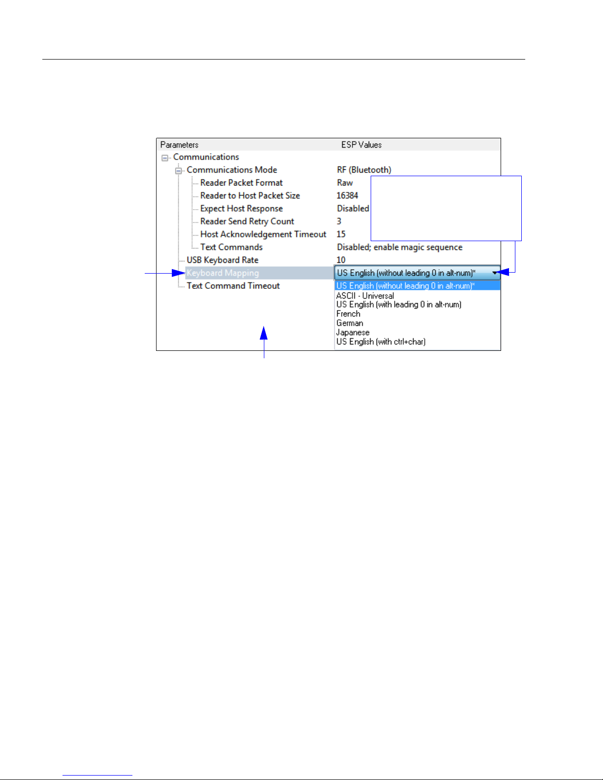
Keyboard Mapping
U.S., No Leading
0
(Default)
U.S. with Leading 0 Keyboard Control Characters
for Non-Printable ASCII
French German Japanese
Universal
Keyboard Mapping
The Keyboard Mapping feature provides alternatives for keyboards that do not conform to
U.S. English mapping. It also allows you to send control characters for non-printable ASCII.
Note: Universal keyboard mapping is slightly slower than the other language-specific
options, because it maps data by reference to the full set of ASCII characters. The
advantage of Universal keyboard mapping is that it allows any language and keyboard
layout to be mapped.
Important: Keyboard Mapping is not to be confused with USB Keyboard Mode, which
has an entirely different function—namely to enable USB cabled communications.
Keyboard Mapping by ESP
4-12 HS-51/HS-51X Wireless Handheld Reader User Manual
Page 53

Communications
USB Keyboard Rate
Requests that the host polls the USB reader at the rate specified (1 to 255 ms).
HS-51/HS-51X Wireless Handheld Reader User Manual 4-13
Page 54

Text Command Timeout
Text Command Timeout
Text Command Timeout allows you to set the maximum time during which a complete
text command from the host must be received. Pending text command data is discarded
when the timeout is exceeded.
4-14 HS-51/HS-51X Wireless Handheld Reader User Manual
Page 55

Communications
Other Communications Mode Commands
Some
programming symbols. These options are explained below.
ESP
Communications options are unique to the software, and do not have corresponding
Reader Packet Format
Data that is sent from the reader to the host in Raw format is sent without packet framing
or check characters.
Packet data is sent with framing (a preamble communicating the amount of data to be
transmitted, and a postamble containing error detection) and check characters, and a
response is expected from the host.
Packet Mode Version 0 is a similar but more streamlined way of sending packetized data.
Reader to Host Packet Size
The Reader to Host Packet Size is the amount of data (in bytes) that is sent to the host in
packet format. This feature allows you to set the maximum allowable packet size.
Expect Host Response
When Expect Host Response is enabled, the reader will re-transmit data if it doesn’t
receive acknowledgement from the host.
Reader Send Retry Count
Reader Send Retry Count sets the number of times the reader will re-transmit data
before abandoning further send attempts. The minimum retry count is 1, which represents
the initial transmission.
Host Acknowledgement Timeout
The Host Acknowledgement Timeout is the amount of time (in seconds) that the reader
will wait for an acknowledgement from the host before re-sending data.
HS-51/HS-51X Wireless Handheld Reader User Manual 4-15
Page 56

Other Communications Mode Commands
Enable Text Commands
Disable Text Commands
(Default)
When Text Commands are set to
Enabled; Suppress Echo, text
that a user enters in the Terminal
will not be shown. When Text
Commands are set to Enabled;
Suppress Echo and Responses,
neither user-entered data or reader
responses will be shown, and only
decoded symbol data will appear in
the Terminal.
See Terminal Right-Click Menu
for a way to change Echo settings
directly in the Terminal view.
When Magic Sequence is enabled, it allows
the user to enable
Text Commands
by entering a predetermined series of keystrokes.
Enter the magic sequence in
this text field and click Send.
Once the magic sequence has been sent, you can send text commands from the same text field.
Text Commands
When the Text Commands feature is enabled, the reader can accept text commands via
USB Virtual COM modes.
Note: Text Commands are not supported in USB HID Mode.
Text Commands by ESP
Entering Magic Sequence
The magic sequence is ;>PA followed by a numeric value of 1, 3, or 7.
1 = Enable Text Commands
3 = Enabled; Suppress Echo
7 = Enabled; Suppress Echo and Responses
In the example below, the magic sequence entered will Enable Text Commands and
Suppress Echo and Responses.
4-16 HS-51/HS-51X Wireless Handheld Reader User Manual
Page 57

5 Read Cycle
Read Cycle by ESP...................................................................................................................... 5-2
Trigger Active ............................................................................................................................... 5-3
Default Continuous Event............................................................................................................. 5-4
Maximum Decodes per Read....................................................................................................... 5-5
Read Cycle Timeout..................................................................................................................... 5-6
Ignore Duplicate Symbol Timeout ................................................................................................ 5-7
Targeting Zone Tolerance ............................................................................................................ 5-8
Morphological Preprocessing ....................................................................................................... 5-9
Camera Settings......................................................................................................................... 5-10
Contents
This section explains Read Cycle parameters, which can be configured to optimize reader
performance in your application.
ESP
can be used to configure reader parameters and then to send and save those parameters
to the reader.
HS-51/HS-51X Wireless Handheld Reader User Manual 5-1
Page 58

Read Cycle by ESP
To change a setting,
double-click the
setting and use your
cursor to scroll
through the options.
Click this button
to bring up the
App Mode view,
and then click the
Read Cycle tab.
To open nested options,
single-click the +.
Read Cycle by ESP
5-2 HS-51/HS-51X Wireless Handheld Reader User Manual
Page 59

Read Cycle
Trigger Active
When a trigger is active, the reader will either decode once and stop or decode continuously,
depending on how this parameter is set. Trigger Active is set to Read Once by default.
Important: Ignore Duplicate Symbol Timeout should be set to a value greater than 0
when Trigger Active is set to Continuous Read.
HS-51/HS-51X Wireless Handheld Reader User Manual 5-3
Page 60

Default Continuous Event
Default Continuous Event
This parameter allows you to determine the default state of the reader.
Idle (Default)
When Default Continuous Event is set to Idle, the reader will remain inactive until triggered.
Show Target
When Default Continuous Event is set to Show Target, the reader will display the target
LEDs but remain inactive until triggered externally.
Read High Density and Wide Angle
Both High Density and Wide Angle will be continuously activated to capture an image.
Read High Density
High Density will be continuously activated to capture an image.
Read Wide Angle
Wide Angle will be continuously activated to capture an image.
Read Primary Field
When Read Primary Field is selected, the most recent field to have produced a Good
Read (High Density or Wide Angle) will be continuously activated to capture an image.
Event Delay
The default Event Delay is 0.100 seconds.
5-4 HS-51/HS-51X Wireless Handheld Reader User Manual
Page 61

Read Cycle
Maximum Decodes per Read
Maximum Decodes per Read allows you to set how many decodes can be performed in
a single read cycle.
HS-51/HS-51X Wireless Handheld Reader User Manual 5-5
Page 62

Read Cycle Timeout
Read Cycle Timeout
Read Cycle Timeout determines the duration of the read cycle. The default Read Cycle
Timeout is 0.500 seconds.
5-6 HS-51/HS-51X Wireless Handheld Reader User Manual
Page 63

Read Cycle
Ignore Duplicate Symbol Timeout
Ignore Duplicate Symbol Timeout sets the reader not to output the same symbol data
multiple times within the time period designated.
HS-51/HS-51X Wireless Handheld Reader User Manual 5-7
Page 64

Targeting Zone Tolerance
Targeting Zone Tolerance
Targeting Zone Tolerance is particularly useful in environments where closely spaced
symbols of various sizes need to be targeted. It allows the reader to narrow the field of
view relative to the size of a symbol, and to determine the distance the target must be from
the symbol for a decode event to occur.
See Window of Interest for more precise control of the active pixel area.
The default Targeting Zone Tolerance is 1600%.
Formula for Calculating Targeting Zone Tolerance:
2 x distance from target to symbol (in pixels) / symbol width or height (in pixels) x 100
5-8 HS-51/HS-51X Wireless Handheld Reader User Manual
Page 65

Read Cycle
Morphological Preprocessing
Morphological Preprocessing allows you to select the method for processing captured
images, and to choose the operator size for that method. It is set to None by default.
Note: This feature is only available in the HS-51X Wireless Handheld Reader.
Erode
Erode increases the dark cell size of a symbol. Useful for increasing the dark cell size of a
dark-on-light Data Matrix symbol.
Dilate
Dilate increases the light cell size of a symbol. Useful for increasing the light cell size of a
light-on-dark Data Matrix symbol.
Size
Size determines the size of the area or “pixel neighborhood” in which the morphological
operation is being performed.
HS-51/HS-51X Wireless Handheld Reader User Manual 5-9
Page 66

Camera Settings
Camera Settings
Camera Settings allow you to set AGC Sampling Mode, to set the percentage values for
Illumination, Exposure, and Gain, to set the AGC Frame Adjust Count, and also to define
Window of Interest dimensions.
AGC Sampling Mode
When AGC Sampling Mode is set to Automatic (default), each time a No Read occurs,
the reader adjusts the gain and exposure for the next capture to optimize symbol contrast.
The values for Illumination, Exposure, and Gain can be set to any value between 0%
and 100%. The default values are shown below.
AGC Frame Adjust Count
Automatic Gain Control (AGC) is a system that controls gain in order to maintain high
performance over a range of input levels. Gain is essentially the ratio of output to input.
Gain settings affect how the reader decodes symbols and captures images.
AGC Frame Adjust Count sets the number of image frames captured and discarded
before the main image capture. This feature gives the gain control time to adjust.
5-10 HS-51/HS-51X Wireless Handheld Reader User Manual
Page 67

Read Cycle
High Density Window of Interest
Wide Angle Window of Interest
Window of Interest
The active pixel area of the image sensor is called the Window of Interest (WOI). The
WOI allows the user to select an area of the field of view in which the desired symbol is located.
The programmable window of interest increases decode speed, improves threshold, and
makes it easy to select specific symbols from among several in the field of view. The user
provides the upper-left pixel location and the size of the window to define the Window of Interest.
Note: The Window of Interest can be changed, but captured images cannot be viewed.
HS-51/HS-51X Wireless Handheld Reader User Manual 5-11
Page 68

Camera Settings
5-12 HS-51/HS-51X Wireless Handheld Reader User Manual
Page 69

Contents
Symbologies by ESP ....................................................................................................................6-2
Data Matrix.................................................................................................................................... 6-3
QR Code .......................................................................................................................................6-4
Aztec Code ...................................................................................................................................6-5
Code 39 ........................................................................................................................................6-6
Code 128 ......................................................................................................................................6-7
BC412 ...........................................................................................................................................6-8
Code 93 ........................................................................................................................................6-9
Codabar ...................................................................................................................................... 6-10
Interleaved 2 of 5 ........................................................................................................................6-11
UPC ............................................................................................................................................6-12
Postal ..........................................................................................................................................6-13
Pharmacode................................................................................................................................ 6-14
GS1 DataBar............................................................................................................................... 6-16
PDF417.......................................................................................................................................6-17
MicroPDF417 ..............................................................................................................................6-18
Composite...................................................................................................................................6-19
Symbology Identifier ...................................................................................................................6-20
6 Symbologies
This section describes the various symbologies that can be decoded by the HS-51 and
HS-51X Wireless Handheld Readers.
ESP
can be used to configure reader parameters and then to send and save those parameters
to the reader.
You can also configure reader parameters by decoding the Data Matrix symbols in this section.
HS-51/HS-51X Wireless Handheld Reader User Manual 6-1
Page 70

Symbologies by ESP
To change a setting,
double-click the
setting and use your
cursor to scroll
through the options.
Click this button
to bring up the
App Mode view,
and then click the
Symbologies
tab.
To open
nested
options,
single-click
the +.
Symbologies by ESP
6-2 HS-51/HS-51X Wireless Handheld Reader User Manual
Page 71

Symbologies
Important: If you disable the Data
Matrix symbology, programming
symbols will not be decodable by
the reader and Data Matrix will
need to be re-enabled using ESP.
Use the Data Matrix Disabled
programming symbol with caution.
(123456789A)
Data Matrix
Data Matrix Enabled (Default) Data Matrix Disabled
Data Matrix Inverse Enabled Data Matrix Inverse Disabled (Default)
Sample Data Matrix Symbol
HS-51/HS-51X Wireless Handheld Reader User Manual 6-3
Page 72

QR Code
(Microscan QR)
QR Code
QR Code Enabled (Default) QR Code Disabled
Sample QR Code Symbol Sample Micro QR Code Symbol
6-4 HS-51/HS-51X Wireless Handheld Reader User Manual
Page 73

Aztec Code
Aztec Code Enabled (Default) Aztec Code Disabled
Sample Aztec Code Symbol
Symbologies
HS-51/HS-51X Wireless Handheld Reader User Manual 6-5
Page 74

Code 39
Code 39
Code 39 Disabled Code 39 Enabled (Default)
Code 39 Checksum Enabled Code 39 Checksum Disabled (Default)
Code 39 Checksum Enabled,
Strip from Result
Code 39 Extended Code 39 Extended
Full ASCII Enabled Full ASCII Disabled (Default)
Sample Code 39 Symbol
6-6 HS-51/HS-51X Wireless Handheld Reader User Manual
Page 75

Code 128
Code 128 Enabled (Default) Code 128 Disabled
Sample Code 128 Symbol
Symbologies
HS-51/HS-51X Wireless Handheld Reader User Manual 6-7
Page 76

BC412
BC412
BC412 Enabled (Default) BC412 Disabled
Sample BC412 Symbol
6-8 HS-51/HS-51X Wireless Handheld Reader User Manual
Page 77

Code 93
Code 93 Enabled (Default) Code 93 Disabled
Sample Code 93 Symbol
Symbologies
HS-51/HS-51X Wireless Handheld Reader User Manual 6-9
Page 78

Codabar
Codabar
Codabar Enabled (Default) Codabar Disabled
Codabar Checksum Enabled Codabar Checksum Disabled (Default)
Codabar Checksum Enabled and Stripped from Result
Sample Codabar Symbol
6-10 HS-51/HS-51X Wireless Handheld Reader User Manual
Page 79

Interleaved 2 of 5
Interleaved 2 of 5 Enabled (Default) Interleaved 2 of 5 Disabled
Symbologies
Interleaved 2 of 5 Checksum Stripped from Result
Interleaved 2 of 5 Checksum Disabled Interleaved 2 of 5 Checksum Enabled
Interleaved 2 of 5 Checksum Enabled and Stripped from Result
Interleaved 2 of 5 Two Digits Off Interleaved 2 of 5 Two Digits On
Interleaved 2 of 5 Four Digits On
Sample Interleaved 2 of 5 Symbol
HS-51/HS-51X Wireless Handheld Reader User Manual 6-11
Page 80

UPC
UPC
Note:
The symbology identifier ‘e’ (Composite) will be returned instead of ‘E’ (UPC/EAN).
UPC Enabled (Default) UPC Disabled
EAN Status Enabled (Default) EAN Status Disabled
UPC-E as UPC-A Enabled UPC-E as UPC-A Disabled (Default)
When
Composite
is enabled, UPC/EAN symbols are processed as Composite symbols.
Sample UPC-E Symbol
Sample UPC-A Symbol
6-12 HS-51/HS-51X Wireless Handheld Reader User Manual
Page 81

Postal
Postal Enabled Postal Disabled (Default)
Supported Postal Symbologies
• USPS OneCode (4CB)
•POSTNET
•PLANET
• Japanese Post
• Australian Post
• Royal Mail
•KIX Code
Symbologies
Sample Postnet Symbol
Sample Royal Mail Symbol
HS-51/HS-51X Wireless Handheld Reader User Manual 6-13
Page 82

Pharmacode
Pharmacode
Pharmacode Enabled Pharmacode Disabled (Default)
Fixed Symbol Length Enabled Fixed Symbol Length Disabled (Default)
Bar Width Status: Mixed (Default) Bar Width Status: All Narrow
Bar Width Status: All Wide Bar Width Status: Fixed Threshold
Decode Direction: Forward (Default) Decode Direction: Reverse
6-14 HS-51/HS-51X Wireless Handheld Reader User Manual
Page 83

Symbologies
Fixed Symbol Length Status
When enabled, the reader will check the symbol length against the symbol length field. If
disabled, any length will be considered valid.
Symbol Length
Specifies the exact number of bars that must be present for the reader to recognize and
decode the Pharmacode symbol.
Minimum Bars
Sets the minimum number of bars that a Pharmacode symbol must have to be considered
valid.
Bar Width Status
If set to Mixed, the reader will autodiscriminate between narrow bars and wide bars. If set
to All Narrow, all bars will be considered as narrow bars. If set to All Wide, all bars will be
considered as wide bars. If set to Fixed Threshold, it will use the fixed threshold value to
determine whether the bars are narrow or wide. The Bar Width Status setting will be
ignored when the reader is able to tell the difference between the narrow and the wide bars.
Direction
Specifies the direction in which a symbol can be read.
Fixed Threshold Value
Used when Bar Width Status is set to Fixed Threshold. Defines the minimum difference
in pixels that will distinguish a narrow bar from a wide bar.
Sample Pharmacode Symbol
HS-51/HS-51X Wireless Handheld Reader User Manual 6-15
Page 84

GS1 DataBar
GS1 DataBar
All GS1 DataBar Enabled (Default) All GS1 DataBar Disabled
GS1 DataBar Expanded Enabled GS1 DataBar Limited Enabled
GS1 DataBar-14 Enabled
Sample DataBar-14 Limited Symbol
Sample DataBar Expanded Symbol
Sample DataBar-14 Symbol
6-16 HS-51/HS-51X Wireless Handheld Reader User Manual
Page 85

PDF417
PDF417 Enabled (Default) PDF417 Disabled
Sample PDF417 Symbol
Symbologies
HS-51/HS-51X Wireless Handheld Reader User Manual 6-17
Page 86

MicroPDF417
MicroPDF417
MicroPDF417 Disabled (Default) MicroPDF417 Enabled
Sample MicroPDF417 Symbol
6-18 HS-51/HS-51X Wireless Handheld Reader User Manual
Page 87

Symbologies
Composite
Composite consists of a 1D component associated with an adjacent 2D component. A
successful decode is required for both the 1D and 2D components before the reader outputs
a result. When Composite is enabled, the unit decodes the 1D component first.
Note:
When Composite is enabled,
The
symbology identifier ‘e’
(Composite) will be returned instead of
Maximum Decodes per Read
Maximum Decodes per Read represents the maximum number of candidate symbols in
the field of view (1 - 100) that can be decoded during a read cycle. Note that decode
speed will decrease as the Maximum Decodes per Read value is increased.
UPC/EAN
symbols are processed as Composite symbols.
‘E’
(UPC/EAN).
Composite Disabled (Default) Composite Enabled
Sample Composite Symbol
HS-51/HS-51X Wireless Handheld Reader User Manual 6-19
Page 88

Symbology Identifier
Symbology Identifier
When Symbology Identifier is enabled, an AIM (Association for Automatic Identification
and Mobility) preamble is added to decoded data output (see the
list). This preamble identifies what kind of symbology has been decoded.
AIM Symbology Identifiers
A Code 39
C Code 128
d Data Matrix
e GS1 DataBar / Composite
E UPC/EAN
AIM Symbology Identifiers
F Codabar
G Code 93
I Interleaved 2 of 5
L PDF417 / MicroPDF417
Q QR Code / Micro QR Code
X Other (Pharmacode)
z Aztec Code
6-20 HS-51/HS-51X Wireless Handheld Reader User Manual
Page 89

7 I/O Parameters
I/O Parameters by ESP................................................................................................................ 7-2
No Read Notification .................................................................................................................... 7-3
Targeting ...................................................................................................................................... 7-4
Beep and Vibrate.......................................................................................................................... 7-5
Button Stay-Down Time ............................................................................................................... 7-6
Button/Trigger Programming ........................................................................................................ 7-7
Data Validation ........................................................................................................................... 7-10
Contents
This section describes how to optimize triggering, and also how to configure the reader’s
beep, vibrate, and LED behavior.
ESP
can be used to configure reader parameters and then to send and save those parameters
to the reader.
You can also configure reader parameters by decoding the Data Matrix symbols in this section.
HS-51/HS-51X Wireless Handheld Reader User Manual 7-1
Page 90

I/O Parameters by ESP
To change a setting,
double-click the
setting and use your
cursor to scroll
through the options.
Click this button to
bring up the App
Mode view, and
then click the
Read Cycle tab.
To open nested options,
single-click the +.
I/O Parameters by ESP
7-2 HS-51/HS-51X Wireless Handheld Reader User Manual
Page 91

I/O Parameters
No Read Notification
No Read Notification allows you to enable or disable user feedback alerting you when a
symbol is not decoded successfully.
The No Read message output is ap/r, indicating that the reader did not decode the symbol.
HS-51/HS-51X Wireless Handheld Reader User Manual 7-3
Page 92

Targeting
Targeting Off
Targeting On (Default)
Targeting
The Targeting parameter allows you to turn the targeting LEDs on or off. They are on by
default.
Read the configuration symbols below to enable or disable Targeting.
7-4 HS-51/HS-51X Wireless Handheld Reader User Manual
Page 93

I/O Parameters
Beep Parameters in ESP
Vibrate Parameters in ESP
Beep Off, Vibrate OnBeep On, Vibrate On (Default)
Beep On, Vibrate Off Beep Off, Vibrate Off
Beep Volume 0% Beep Volume 33%
Beep Volume 67%
Beep Volume 100% (Default)
Beep and Vibrate
The Beep and Vibrate parameters allow you to configure the beep and vibrate behavior of
the reader.
Beep and Vibrate are enabled by default. Beep volume is 100% by default.
Read the configuration symbols below to configure Beep and Vibrate.
HS-51/HS-51X Wireless Handheld Reader User Manual 7-5
Page 94

Button Stay-Down Time
Button Stay-Down Time
Button Stay-Down Time sets the amount of time (in seconds) that the reader will continue
to process the current “decode symbol” event. The reader will behave as if the trigger is
being activated for this specified amount of time.
7-6 HS-51/HS-51X Wireless Handheld Reader User Manual
Page 95

I/O Parameters
Handle
Trigger
Button/Trigger Programming
Button/Trigger Programming allows you to determine the reader’s behavior when the
Handle Trigger, Top Front Button, or Top Back Button are held down.
Handle
The Handle Trigger can be configured as Disabled, or to Show Target, Read High
Density and Wide Angle (Default), Read High Density, Read Wide Angle, or Read
Primary Field.
Disabled
Handle Trigger functionality will be disabled.
Show Target
The target LEDs will illuminate when the Handle Trigger is held down.
Read High Density and Wide Angle (Default)
Both High Density and Wide Angle will be activated to capture an image when the
Handle Trigger is held down.
Rear High Density
High Density will be activated to capture an image when the Handle Trigger is held down.
Read Wide Angle
Wide Angle will be activated to capture an image when the Handle Trigger is held down.
Read Primary Field
The most recent field (High Density or Wide Angle) to have produced a Good Read will
be activated to capture an image when the Handle Trigger is held down.
HS-51/HS-51X Wireless Handheld Reader User Manual 7-7
Page 96

Button/Trigger Programming
Top Front Button
Top Front
The Top Front Button can be configured as Disabled, or to Show Target, Read High
Density and Wide Angle (Default), Read High Density, Read Wide Angle, or Read
Primary Field.
Disabled
Top Front Button functionality will be disabled.
Show Target
The target LEDs will illuminate when the Top Front Button is held down.
Read High Density and Wide Angle (Default)
Both High Density and Wide Angle will be activated to capture an image when the Top
Front Button is held down.
Rear High Density
High Density will be activated to capture an image when the Top Front Button is held down.
Read Wide Angle
Wide Angle will be activated to capture an image when the Top Front Button is held down.
Read Primary Field
The most recent field (High Density or Wide Angle) to have produced a Good Read will
be activated to capture an image when the Top Front Button is held down.
7-8 HS-51/HS-51X Wireless Handheld Reader User Manual
Page 97

I/O Parameters
Top Back Button
Top Back
The Top Back Button can be configured as Disabled, or to Show Target, Read High
Density and Wide Angle (default), Read High Density, Read Wide Angle, or Read
Primary Field.
Disabled
Top Back Button functionality will be disabled.
Show Target
The target LEDs will illuminate when the Top Back Button is held down.
Read High Density and Wide Angle (Default)
Both High Density and Wide Angle will be activated to capture an image when the Top
Back Button is held down.
Rear High Density
High Density will be activated to capture an image when the Top Back Button is held down.
Read Wide Angle
Wide Angle will be activated to capture an image when the Top Back Button is held down.
Read Primary Field
The most recent field (High Density or Wide Angle) to have produced a Good Read will
be activated to capture an image when the Top Back Button is held down.
HS-51/HS-51X Wireless Handheld Reader User Manual 7-9
Page 98

Data Validation
Data Validation
Data Validation is used to confirm that a decoded string from the imager has complied
with a particular company, industry, or ISO standard. HS-51/HS-51X Data Validation is
compliant with Department of Defense Unique Identification and ISO/IEC 15434 (Information
Technology – Transfer Syntax for High-Capacity ADC Media) requirements.
Unique Identification
Unique Identification is a mandatory Department of Defense (DoD) requirement on all
solicitations issued January 1, 2004 or later. This policy mandates the use of Unique Item
Identifiers (UIIs) encoded within Data Matrix symbols on equipment and parts procured by
DoD. The HS-51/HS-51X complies with Department of Defense Standard Practice Identification
(MIL-STD-130).
Once the imager decodes the Data Matrix symbol, and if Unique Item Identifier (UII), Current
Part Number (CPN), and Lot/Batch Number (LBN) are turned on, the HS-51/HS-51X
checks the ISO/IEC 15434 syntax with ISO/IEC 15418 (ANSI MH10.8.2 – AI and DI) and
ISO/IEC 21849 (ATA – TEI) semantics to construct the UII, CPN, and LBN.
Unique Identification Features
The following data output options are applicable to Data Matrix ECC 200 symbols only and
have no effect on other symbologies.
UII Enabled Allows the imager to read only message streams encoded in Data Matrix
ECC 200 symbols, then to construct and output a UII string. The message
streams include validation of Unique Item Identifier (UII), Current Part
Number (CPN), and Lot/Batch Number (LBN) strings. When the imager
decodes a symbol but the symbol data does not compy with UII format, it
will stop capturing images and the green LED will illuminate without
beeping, vibrating, or outputing the string.
UII Enabled with
Pass Through
UII Enabled with
Error Messages
Data Validation
Disabled
Allows the imager to read UII messages in Data Matrix ECC 200 symbols
and non-UII messages in any type of symbols. The imager’s behavior is
the same as with UII Enabled.
Allows the imager to read UII messages in Data Matrix ECC 200 symbols
and output detailed information such as construction type, data components,
or error messages. The imager’s behavior is the same as with UII
Enabled.
Disables both UII and ISO/IEC 15434 data validation.
7-10 HS-51/HS-51X Wireless Handheld Reader User Manual
Page 99

I/O Parameters
Unique Identification Output Examples
UII Enabled
UII:UN123456789ABCDEFG
CPN:87654321
LBN:87654321
UII:12345678 CPN:87654321
UII:12345678 LBN:87654321
UII Enabled with Pass Through
UII:UN123456789ABCDEFG
CPN:87654321
LBN:87654321
UII:12345678 CPN:87654321
UII:12345678 LBN:87654321
DATA:Microscan Precision Data Acquisition and Control Solutions
UII Enabled with Error Messages
UII:UN123456789ABCDEFG;Construct_1;25SUN123456789ABCDEFG;;;;;;
CPN:87654321;PNR;PNR 87654321;;;;;;
LBN:87654321;30T;30T87654321;;;;;;
UII:12345678 CPN:87654321;Construct_1_2/PNR;UID 12345678;PNR 87654321;;;;;
UII:12345678 LBN:87654321;Construct_1/30T;25S12345678;30T87654321;;;;;
(15434 ERROR: HEADER - 1ST POSITION);Microscan Precision Data Acquisition and
Control Solutions;;;;;;;
Data Validation Disabled
The imager will return to normal output behavior without performing data validation.
HS-51/HS-51X Wireless Handheld Reader User Manual 7-11
Page 100

Data Validation
ISO/IEC 15434
ISO/IEC 15434 specifies a transfer structure, syntax, and coding of messages and data
formats when using high capacity automatic data capture (ADC) technologies.
The following ISO/IEC 15434 data output options are applicable to Data Matrix ECC 200
symbols only and have no effect on other symbologies.
ISO/IEC 15434
Enabled
ISO/IEC 15434
Enabled with Error
Messages
Data Validation
Disabled
Allows the imager to read only ISO/IEC 15434-compliant message
streams in Data Matrix ECC 200 symbols then output the ISO/IEC 15434
string. This implementation only checks the header/trailer format and
proper format indicator (00-99 and DD). The output string has a prefix, a
format indicator, and data components.
Allows the imager to read only ISO/IEC 15434-compliant messages in
Data Matrix ECC 200 symbols and output detailed information such as
prefix, format indicator, data components, or error messages.
Disables both UII and ISO/IEC 15434 data validation.
ISO/IEC 15434 Output Examples
ISO/IEC 15434 Enabled
(15434);05;0100061414199999;211A0B9C3D6;;;;;
(15434);06;7L0A1B3C;1P4202435;S10936;;;;
(15434);06;17V0A1B2;1P4202435;S10936;;;;
ISO/IEC 15434 Enabled with Error Messages
(15434);05;0100061414199999;211A0B9C3D6;;;;;
(15434);06;7L0A1B3C;1P4202435;S10936;;;;
(15434);06;17V0A1B2;1P4202435;S10936;;;;
(15434 ERROR: HEADER - 3RD POSITION);[)<▲DD↔CAG 12345↔SER
67890123▲♦;;;;;;;
(15434 ERROR: TRAILER - END OF TRANSMISSION);[)>▲12↔CAG 12345↔SER
67890123▲♣;;;;;;;
(15434 ERROR: HEADER - GROUP SEPARATOR);[)>▲12▲CAG 12345♦029SER
67890123▲♦;;;;;;;
Data Validation Disabled
The imager will return to normal output behavior without performing data validation.
7-12 HS-51/HS-51X Wireless Handheld Reader User Manual
 Loading...