

Page 1
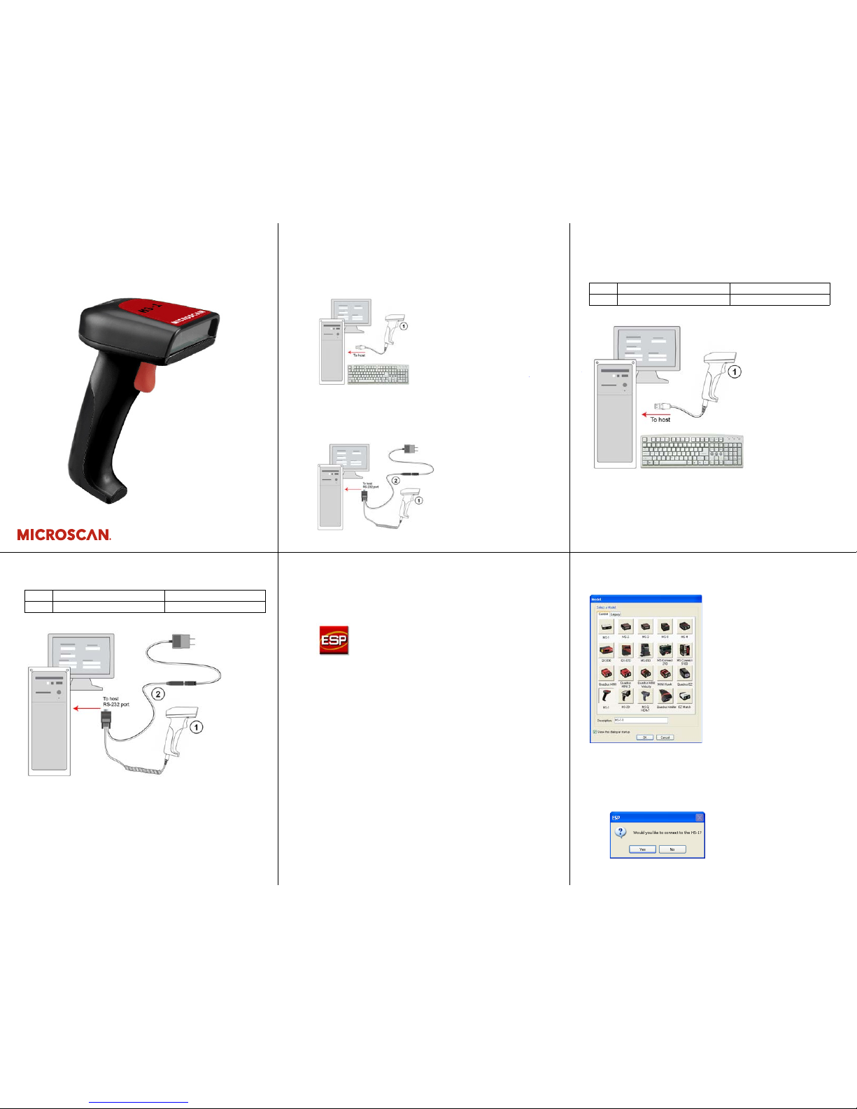
Step 2 — Set Up Hardware (USB)
Note: The USB interface draws its power from the host.
Hardware for USB
Installation Steps for USB
1. Attach the RJ50 end of the scanner cable to the bottom of
the handle.
2. Attach the USB end of the cable to a USB port on the host
computer.
1 HS-1 Handheld Scanner 98-000106-01
2 USB Cable Included
Step 1 — Check Required Hardware
HS-1 USB Hardware
1. HS-1 Handheld Scanner
2. USB Cable
HS-1 RS-232 Hardware
1. HS-1 Handheld Scanner
2. RS-232 Kit
3. USB Virtual COM Cable (if required by application; not shown)
Quick Start Guide
HS-1 Handheld Scanner
P/N 83-110001 Rev A
Step 2 — Set Up Hardware (RS-232)
Hardware for RS-232
Installation Steps for RS-232
1. Power-off the host.
2. Attach the RJ50 end of the scanner cable to the bottom of
the handle.
3. Attach the 15-pin Dsub end of the scanner cable to the
host computer.
4.
Plug in the power supply.
1 HS-1 Handheld Scanner 98-000106-01
2 RS-232 Kit 98-000111-01
Step 3 — Install ESP
ESP Software
can be found on the Microscan To ols CD that is p ackaged
with the HS-1.
1. Follow the prompts to install ESP from the CD.
2. Click on the ESP icon to run the program.
Note: ESP can also be installed from the Download Center at
www.microscan.com.
Minimum System Requirements
• 166 MHz Pentium processor (Pentium II processor recommended)
• Windows Vista, XP, or 2000 operating system
• Internet Explorer 5.0 or higher
• 64 MB minimum RAM (128+ MB RAM recommended)
• 80 MB hard drive space
• 800 x 600 minimum 256 color display (1024 x 768 32-bit color
recommended)
Step 4 — Select Model
When you start ESP, the following menu will appear:
1. Click the HS-1 button and then click OK. If you do not want
to make this selection every time you start ESP, uncheck
“Show this dialog at startup”.
2. Select the default scanner name (HS-1-1), or type a name
of your choice in the Description text field and click OK.
3. Click Yes when this dialog appears:
Page 2
Copyright ©2009 Microscan Systems, Inc.
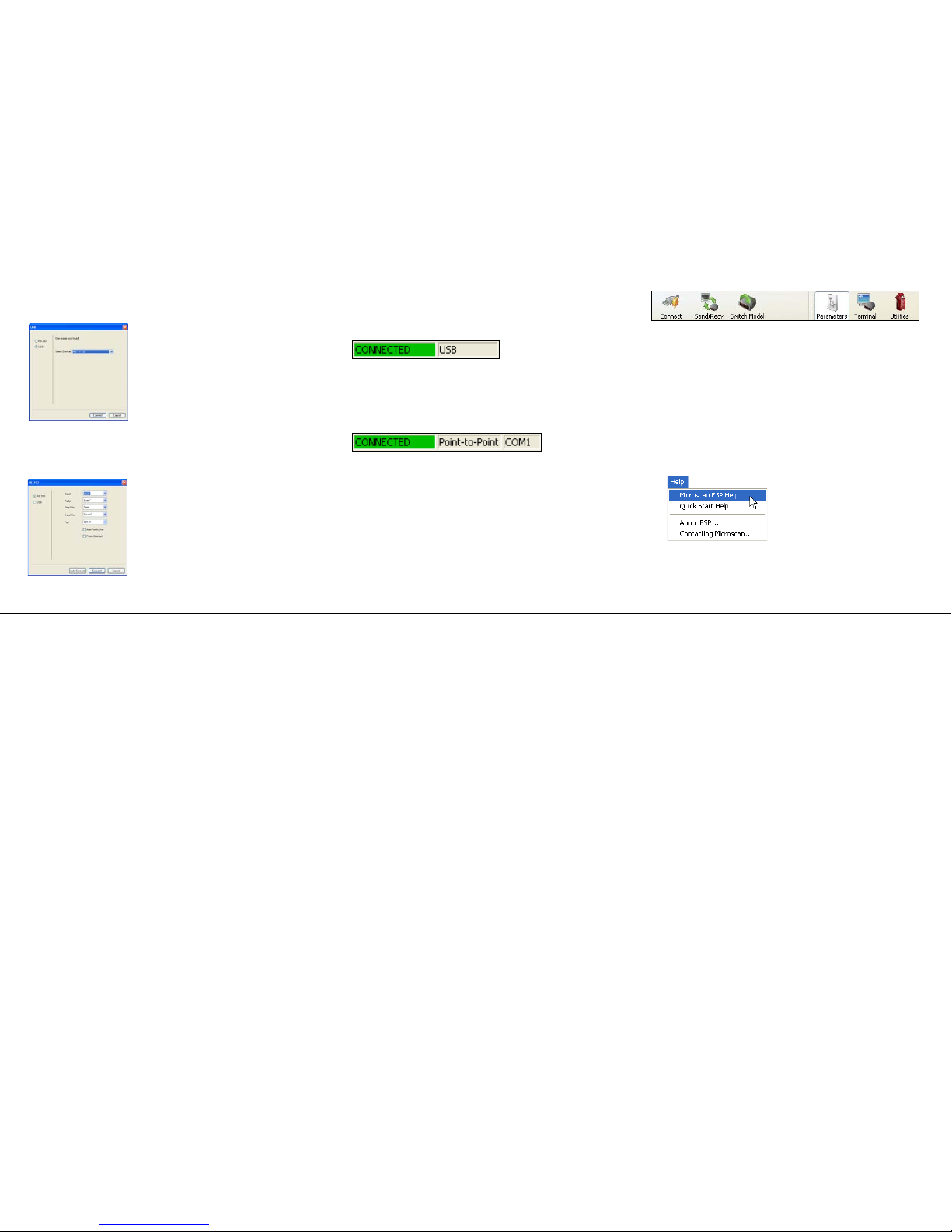
Step 7 — Configure the Scanner
• Click the Connect button to establish communications
between ESP and the HS-1.
• Click the Send/Recv button to send or receive commands.
•Click the Switch Model button to open the model menu, or to
return to a previous model.
• Click the Parameters button to show the tabbed tree controls
for Communication, Read Cycle, and Symbologies.
• Click the Terminal button to display decoded symbol data,
and to send serial commands to the HS-1 using text or macros.
• Click the Utilities button to determine the Differences from
Default in the current settings and to identify the HS-1’s firmware.
For further details, see Microscan ESP Help in the dropdown
Help menu.
Step 6 —
Connect to ESP
USB
When you are connected successfully, the
CONNECTED
message
will appear in a green box in the status bar at the bottom right of
the screen.
You are now ready to configure the USB HS-1 using ESP.
RS-232
When you are connected successfully, the
CONNECTED
message
will appear in a green box in the status bar at the bottom right of
the screen.
You are now ready to configure the RS-232 HS-1 using ESP.
Step 5 — Select Protocol
Select the communications protocol you are using and click Next.
USB
ESP will detect the scanner. The Select Device dialog will
show the name of the scanner and the firmware version Click
Connect.
RS-232
Check Baud Rate, Parity, Stop Bits, Data Bits, and Port, and
click Connect.
 Loading...