

Page 1
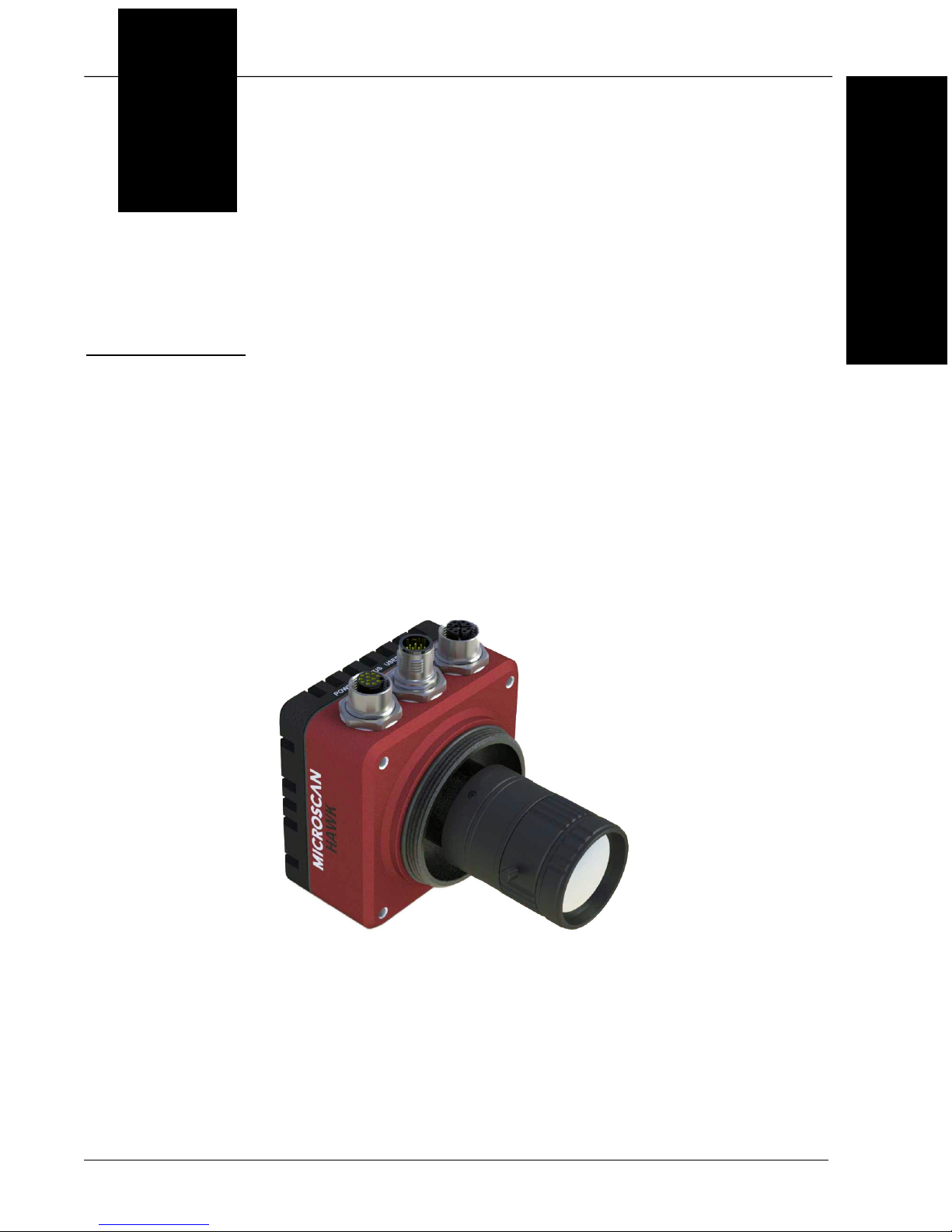
HAWK MV-4000
Smart Camera Guide
84-9007433-02 Rev A
Page 2

Copyright ©2017
Omron Microscan Systems, Inc.
Tel: +1.425.226.5700 / 800.762.1149
Fax: +1.425.226.8250
All rights reserved. The information contained herein is proprietary and is provided solely for the purpose of
allowing customers to operate and/or service Omron Microscan manufactured equipment and is not to be
released, reproduced, or used for any other purpose without written permission of Omron Microscan.
Throughout this manual, trademarked names might be used. We state herein that we are using the names to the
benefit of the trademark owner, with no intention of infringement.
Disclaimer
The information and specifications described in this manual are subject to change without notice.
Latest Manual Version
For the latest version of this manual, see the Download Center on our web site at: www.microscan.com.
Technical Support
For technical support, e-mail:
Americas_support@microscan.com
EMEA_support@microscan.com
APAC_support@microscan.com
China_support@microscan.com
Warranty
For current warranty information, see: www.microscan.com/warranty.
Omron Microscan Systems, Inc.
United States Corporate Headquarters
+1.425.226.5700 / 800.762.1149
United States Northeast Technology Center
+1.603.598.8400 / 800.468.9503
European Headquarters
+31.172.423360
Asia Pacific Headquarters
+65.6846.1214
Page 3
Statements of Compliance
FCC
HAWK MV-4000 Smart Cameras have been tested for compliance with FCC (Federal Communications
Commission) requirements and have been found to conform to applicable FCC standards.
To comply with FCC RF exposure compliance requirements, this device must not be co-located
with or operate in conjunction with any other antenna or transmitter.
Changes or modifications not expressly approved by the party responsible for compliance could
void the user’s authority to operate the equipment.
CE
HAWK MV-4000 Smart Cameras have been tested for compliance with CE (Conformité Européenne)
requirements, and have been found to conform to applicable CE standards.
The CE Declaration of Conformity for this product is available from Microscan upon request.
HAWK MV-4000 Smart Cameras have been tested by an independent electromagnetic compatibility
laboratory in accordance with the applicable specifications and instructions.
UL
HAWK MV-4000 Smart Cameras have been tested for compliance with UL (Underwriters Laboratories)
standards and guidelines, and have been found to conform to applicable UL standards.
Restricted Substances
See www.microscan.com/quality for Microscan compliance statements related to all applicable
restricted substances.
Page 4
FCC Compliance Statement
Warning: Changes or modifications to these units not expressly approved by the party responsible for the compliance
could void the user's authority to operate this equipment.
The use of shielded cables for connections of these devices to other peripherals is required to meet the regulatory
requirements.
Note: These devices comply with Part 15 of FCC Rules. Operation is subject to the following two conditions:
1. These devices may not cause harmful interference, and
2. These devices must accept any interference received, including interference that may cause undesired operation.
This equipment has been tested and found to comply with the limits for Class A digital devices, pursuant to Part 15
of the FCC Rules. These limits are designed to provide reasonable protection against harmful interference when the
equipment is operated in a commercial environment. This equipment generates, uses, and can radiate radio frequency
energy and, if not installed and used in accordance with the instruction manual, may cause harmful interference to
radio communications. Operation of these devices in a residential area is likely to cause harmful interference in
which case the user will be required to correct the interference at his/her own expense.
Industry Canada Compliance Statement
These digital apparatuses do not exceed the Class A limits for radio noise emission from digital apparatuses set out
in the Radio Interference Regulations of Industry Canada.
Ces appareils numériques n’émettent pas de bruits radioélectriques dépassant les limites applicables aux appareils
numériques de Classe A prescrites dans le Règlement sur le brouillage radioélectrique édicté par Industrie Canada.
EU Notice (European Union)
WARNING: These are class A products. In a domestic environment these products may cause radio interference in
which case the user may be required to take adequate measures.
AVERTISSEMENT: Ces appareils sont des produits informatiques de Classe A. Lorsque ces appareils sont utilisent
dans un environnement résidentiel, ces produits peuvent entraîner des interférences radioélectriques. Dans ce cas,
l'usager peut être prié de prendre des mesures correctives appropriées.
This device complies with Directive 2004/108/EC for Class A digital devices. They have been tested and found to
comply with EN55022/CISPR22 and EN55024/CISPR24.
Ces unités sont conformes à la Directive communautaire Directive 2004/108/EC pour les unités numériques de
Classe A. Les tests effectués one prouvé qu’elles sont conformes aux normes EN55022/CISPR22 et EN55024/CISPR24.
Directive on Waste Electrical and Electronic Equipment (WEEE)
Europe
(English) European user’s information – Directive on Waste Electrical and Electronic Equipment (WEEE)
Please refer to the Microscan web site (www.microscan.com) for recycling information.
(Français) Informations aux utilisateurs Européens – Règlementation des déchets d’équipements électriques
et électroniques (DEEE)
Se référer au site Web de Microscan (www.microscan.com) pour l’information concernant le recyclage.
(Deutsch) Information für europäische Anwender – Europäische Regelungen zu Elektro- und Elektronikaltgeräten
(WEEE)
Bitte wenden Sie sich an dem Microscan-Website (www.microscan.com) für Recycling Informationen.
(Italiano) Informazioni per gli utenti europei – Direttiva sui rifiuti di apparecchiature elettriche ed elettroniche
(RAEE)
Si prega di riferirsi al sito Web Microscan (www.microscan.com) per le informazioni di riciclaggio.
Page 5
HAWK MV-4000 Safety Warnings and Symbols Key
Before using the HAWK MV-4000 Smart Camera, you should be aware of the meanings of the
safety warnings and symbols on the device. The following is a list of HAWK MV-4000 symbols and
their meanings.
Symbol
a
Description
• Caution: Read the HAWK MV-4000 Smart Camera Guide
b
(this document)
before using the device. The guide contains product specifications, hardware
configurations, connector and cable pin assignments, wiring instructions,
accessory configuration instructions, and additional information related to the
operation of the device.
•
This product must be used as specified. The protection provided by its components
may be compromised if the product is used improperly.
• Refer to the electrical specifications section in the HAWK MV-4000 Smart
Camera Guide for voltage and current ratings.
• There are no user-serviceable parts inside this product. Contact Microscan for
repair or replacement.
• To maintain IP67 conformity, all unused connectors on the HAWK MV-4000
must be capped and the optional IP case must be screwed firmly into place.
• This product meets Category 1 installation requirements per industry standards.
• This product is designed for use in a Pollution Degree 2 environment per
industry standards
c
.
• This product is designed for indoor use only.
• This product is designed for operation at temperatures ranging from 0° C to 50° C.
• This product is not intended for use at altitudes exceeding 2000 meters.
• DC current only.
• The HAWK MV-4000 can only be powered using a 24VDC power source.
a. Symbol color or shape may be slightly different on the product.
b. HAWK MV-4000 Smart Camera Guide available on Tools Drive (P/N 37-000010-01) or at www.microscan.com.
c. Per CAN/CSA-C22.2 No 61010-1-12, UL std. No 61010-1 (3rd edition), and EN Std. No. 61010-1 (3rd edition).
Page 6

Contents
PREFACE Welcome viii
Purpose of This Manual viii
Manual Conventions viii
CHAPTER 1 Introduction 1-1
Product Summary 1-2
Features and Benefits 1-3
Applications 1-4
Package Contents 1-4
HAWK MV-4000 Smart Camera Models 1-5
HAWK MV-4000 Part Number Structure 1-6
CHAPTER 2 System Components 2-1
Hardware Components and Accessories 2-2
HAWK MV-4000 Dimensions 2-6
Label Information 2-10
Mounting, Connecting, and Wiring 2-11
Connecting to the I/O Interface 2-17
Input/Output Wiring Using Flying Lead Cable 61-9000151-01 2-37
Ground and Shield Considerations 2-38
Electrical and I/O Specifications 2-40
Environmental Specifications 2-41
Status Indicators 2-42
Adding a HAWK MV-4000 to a Network 2-43
Setting Up a Job in AutoVISION 2-44
Trigger Debounce 2-49
Setting Up Partial Scan 2-51
CHAPTER 3 Lighting 3-1
Illumination 3-2
External Illumination Control and Wiring 3-3
HAWK MV-4000 Smart Camera Guide vi
Page 7

APPENDIX A Selecting a Lens A-1
Lens Selection A-2
Lens Specifications A-4
APPENDIX B Cable Specifications B-1
61-9000132-01 Cable, Adapter, HAWK MV-4000 to QX-1 B-2
61-9000134-0X Cable, Ethernet, X-Code/RJ45 CAT 6A, 1 m, 3 m, 5 m B-3
M12 to Smart Series and Camera Cables B-4
97-000012-01 Power Supply, M12 12-Pin Socket, 1.3 m B-5
99-000020-02 Trigger, M12 4-Pin Plug, NPN, Dark On, 2 m B-6
APPENDIX C General Specifications C-1
Sensor Board C-2
CPU Board C-3
VGA/USB Port C-4
Electrical Specifications C-5
Environmental Specifications C-6
Dimensions C-7
Digital I/O and Power Adapter Cable Connector C-8
100/1000 Base-T Connector C-10
VGA/USB Connector C-11
Liquid Lens Connector C-13
APPENDIX D MVMonitor Web Page D-1
Using the MVMonitor Web Page D-2
APPENDIX E CloudLink Web HMI E-1
Connecting E-2
Application Overview E-3
Application Bar E-4
Pages, Panels, and Widgets E-5
APPENDIX F Serial Commands F-1
APPENDIX G Operating System Save and Restore G-1
Restore to Microscan Factory Settings G-2
Access Microscan Rescue Utility G-7
Back Up/Restore/Capture the OS Image with Microscan Rescue Utility G-11
APPENDIX H OS Config Application H-1
Global Settings Tab H-2
Write Filter Tab H-3
Capture OS Tab H-4
Languages Tab H-5
eMMC Tab H-6
EULA Tab H-7
vii HAWK MV-4000 Smart Camera Guide
Page 8

Preface
PREFACE Welcome
Purpose of This Manual
This manual contains detailed information about how to configure and operate the HAWK
MV-4000 Smart Camera.
Manual Conventions
• Items emphasizing important information are bolded.
• Menu selections, menu items, and entries in screen images are indicated as: Run
(triggered), Modify..., etc.
HAWK MV-4000 Smart Camera Guide viii
Page 9
1
CHAPTER 1 Introduction
1
Introduction
HAWK MV-4000 Smart Camera
HAWK MV-4000 Smart Camera Guide 1-1
Page 10

Chapter 1 Introduction
Product Summary
The HAWK MV-4000 is Microscan’s high-performance smart camera. It is the middle tier
in a suite of products that includes MicroHAWK MV Smart Cameras at the lower end and
Visionscape PC-Based GigE Camera systems at the higher end.
The HAWK MV-4000 is a C-Mount camera fully accessorized for use with Microscan’s
NERLITE Smart Series of machine vision lighting products.
The HAWK MV-4000 features a full range of sensors, from 0.3 MP to 5 MP in both
monochrome and color. The sensors are all based on the ON Semiconductor PYTHON
CMOS series. All sensors have a 4.8 μm pixel size enabling them to capture very high-quality
images at very high frame rates.
The combination of C-Mount lens, external lighting, and 0.3 to 5 MP sensors allows users
to configure the system to accomplish virtually any application, from reading tiny 1D or 2D
symbols on flat panel displays to inspecting entire automotive assemblies.
The processor is a Dual-Core Intel Celeron N2807 with 2 GB of RAM and 32 GB of eMMC
(flash disk) storage memory. The HAWK MV-4000 is able to store, load, and run up to 50 simple
or complex jobs. Processing times reach near-PC speeds, enabling the camera to keep up with
line rates of up to 6,000 parts per minute and speeds of over 300 inches per second.
The camera is also equipped with real-time Digital I/O, RS-232, and GigE Ethernet ports.
Through these communication channels, the user can control and trigger the unit, as well as
receive results and images. The GigE port allows images to be ported to a display at nearly
the same speed as the frame rate. EtherNet/IP allows seamless integration with most of the
key PLC platform devices on the market.
Finally, like MicroHAWK MV or Visionscape PC-Based GigE Camera systems, the HAWK
MV-4000 can be programmed through a variety of user interfaces. This includes
AutoVISION, which is a highly intuitive and simple UI that can be mastered by a casual
user on the factory floor. It also includes Visionscape FrontRunner, which is the full
professional UI offering the entire Visionscape tool set to the user, including scripting tools
that allow the user to create custom tools and algorithms. The HAWK MV-4000 can be
controlled and monitored through custom web interfaces or UIs specifically designed and
programmed for the application using Visionscape’s powerful .NET controls.
1-2 HAWK MV-4000 Smart Camera Guide
Page 11

Features and Benefits
Features and Benefits
• Standard-fidelity and high-fidelity C-Mount optics;
• Designed for use with NERLITE Smart Series machine vision illuminators;
• Full range of sensors with speeds up to 290 frames per second;
– 0.3 MP (640 x 480), 1.3 MP (1280 x 1024), 2.0 MP (1920 x 1200), and 5.0 MP
(2592 x 2048) resolution;
– Monochrome and color versions;
1
Introduction
–4.8
• Dual-Core Intel processor capable of near-PC processing speeds
• 32 GB of eMMC and 2 GB of RAM for storing and running many large and complex jobs;
• Real-time Digital I/O, RS-232, and GigE comm. channels;
• IP67-rated design (when lens cover is installed) for use in industrial environments;
• Simplified configuration with AutoVISION Software;
• Advanced configuration with Visionscape FrontRunner software;
• Custom UI creation and machine integration using Visionscape .NET controls, Rest
APIs, and serial command set;
• HMI via VGA and USB connectivity, or via web using CloudLink UI;
• Scalable down to Microscan’s MicroHAWK MV Smart Camera;
• Scalable up to Microscan’s Multi-GigE Camera PC-Based Systems.
μm
pixel size;
HAWK MV-4000 Smart Camera Guide 1-3
Page 12

Chapter 1 Introduction
Applications
• Fast-moving consumer goods inspection;
• Automotive assembly inspection and verification;
• High-precision gauging and guidance;
• Electronics assembly verification and identification;
• Semiconductor packaging and component inspection;
• 1D, 2D, and OCR symbol reading for any size mark;
• Fast inline 1D and 2D symbol verification and validation;
• Color inspection and verification.
Package Contents
Before you install AutoVISION Software and connect the HAWK MV-4000 Smart Camera,
please take a moment to confirm that the following items are present:
• HAWK MV-4000 Smart Camera;
• HAWK MV-4000 Adapter Cable, 61-9000132-01;
• Microscan Tools Drive – USB flash drive containing AutoVISION Software and full
recovery image for the HAWK MV-4000;
• Required accessories such as a power supply cable.
1-4 HAWK MV-4000 Smart Camera Guide
Page 13
HAWK MV-4000 Smart Camera Models
HAWK MV-4000 Smart Camera Models
The table below lists and describes the basic HAWK MV-4000 Smart Camera models not
including lenses, lens caps, accessories, and lighting. PPP at the end of each part number
represents the license level. Each model can be ordered with one of the following five
license levels:
100 – AutoVISION Sensor (Includes AutoVISION’s machine vision tools only);
102 – AutoVISION (Includes AutoVISION’s machine vision and auto ID tools);
103 – AutoVISION + Visionscape (Includes AutoVISION’s machine vision and auto ID
tools and full Visionscape);
104 – AutoVISION + Verification (Includes AutoVISION’s machine vision and auto ID
tools, symbol verification, and OCR verification);
105 – AutoVISION + Visionscape + Verification (Includes all AutoVISION and Visionscape
capabilities).
Additional part numbers that include lenses and lens caps are available in the Microscan
Product Pricing Catalog and through Microscan’s Order Management System. Additional
accessories and lights can be purchased separately.
1
Introduction
Part Number Camera Name Description
8X11-0000-PPPP HAWK MV-4000-03 HAWK MV-4000, Monochrome, 0.3 MP (640 x 480), 1/4” CMOS Sensor
8X12-0000-PPPP HAWK MV-4000-13 HAWK MV-4000, Monochrome, 1.3 MP (1280 x 1024), 1/2” CMOS Sensor
8X13-0000-PPPP HAWK MV-4000-20 HAWK MV-4000, Monochrome, 2.0 MP (1920 x 1200), 2/3” CMOS Sensor
8X14-0000-PPPP HAWK MV-4000-50 HAWK MV-4000, Monochrome, 5.0 MP (2592 x 2048), 1” CMOS Sensor
8X15-0000-PPPP HAWK MV-4000-03C HAWK MV-4000, Color, 0.3 MP (640 x 480), 1/4” CMOS Sensor
8X16-0000-PPPP HAWK MV-4000-13C HAWK MV-4000, Color, 1.3 MP (1280 x 1024), 1/2” CMOS Sensor
8X17-0000-PPPP HAWK MV-4000-20C HAWK MV-4000, Color, 2.0 MP (1920 x 1200), 2/3” CMOS Sensor
8X18-0000-PPPP HAWK MV-4000-50C HAWK MV-4000, Color, 5.0 MP (2592 x 2048), 1” CMOS Sensor
Note:
All models include dual-core Celeron® CPU, 2 GB of memory, 32 GB eMMC storage memory, and run Microsoft® Windows®
10 IoT Enterprise (64 bit).
HAWK MV-4000 Smart Camera Guide 1-5
Page 14

Chapter 1 Introduction
HAWK MV-4000 Part Number Structure
HAWK MV-4000 part numbers follow the format 8ABS-LFFA-LPPP.
8 = HAWK MV-4000 Smart Camera
(A) Enclosure
0 = No Lens Cover
1 = 50 mm Lens Cover
2 = 70 mm Lens Cover
(B) Software = 1 (Machine Vision)
(S) Sensor Type
1 = VGA, Mono
2 = 1.3 MP, Mono
3 = 2 MP, Mono
4 = 5 MP, Mono
5 = VGA, Color
6 = 1.3 MP, Color
7 = 2 MP, Color
8 = 5 MP, Color
(L) Lens
0 = No Lens
1 = 2/3” Standard Def.
2 = 2/3” High Def.
3 = 1” High Def.
(FF) Lens Focal Length
00 = No Lens
XX = Focal Length (mm)
(A) Accessories = 0
(L) Lighting = 0
(PPP) License
100 = AutoVISION Sensor
101 = AutoVISION
102 = AutoVISION + Visionscape
103 = AutoVISION + Verification
104 = AutoVISION + Visionscape + Verification
1-6 HAWK MV-4000 Smart Camera Guide
Page 15

2
CHAPTER 2 System Components
This section contains specific information about system components as well
as information to help you connect your HAWK MV-4000 Smart Camera.
2
System Components
Note: There are no user-serviceable parts inside the camera.
HAWK MV-4000 Smart Camera Guide 2-1
Page 16
Chapter 2 System Components
Hardware Components and Accessories
This section contains information about system components as well as information to help
you connect the HAWK MV-4000 Smart Camera. Specific information describes connectors,
adapters, cables, pinouts, and signals.
HAWK MV-4000 Smart Cameras (All cameras ship with an adapter cable.)
0.3 Megapixel Mono
8011-0000-0100 HAWK MV-4000-03, 0.3 Megapixel (640 x 480), Mono, AutoVISION Sensor
8011-0000-0101 HAWK MV-4000-03, 0.3 Megapixel (640 x 480), Mono, AutoVISION
8011-0000-0102 HAWK MV-4000-03, 0.3 Megapixel (640 x 480), Mono, AutoVISION + Visionscape
8011-0000-0103 HAWK MV-4000-03, 0.3 Megapixel (640 x 480), Mono, AutoVISION + Verification / OCV
8011-0000-0104 HAWK MV-4000-03, 0.3 Megapixel (640 x 480), Mono, AutoVISION + Visionscape + Verification / OCV
1.3 Megapixel Mono
8012-0000-0100 HAWK MV-4000-13, 1.3 Megapixel (1280 x 1024), Mono, AutoVISION Sensor
8012-0000-0101 HAWK MV-4000-13, 1.3 Megapixel (1280 x 1024), Mono, AutoVISION
8012-0000-0102 HAWK MV-4000-13, 1.3 Megapixel (1280 x 1024), Mono, AutoVISION + Visionscape
8012-0000-0103 HAWK MV-4000-13, 1.3 Megapixel (1280 x 1024), Mono, AutoVISION + Verification / OCV
8012-0000-0104 HAWK MV-4000-13, 1.3 Megapixel (1280 x 1024), Mono, AutoVISION + Visionscape + Verification / OCV
2.0 Megapixel Mono
8013-0000-0100 HAWK MV-4000-20, 2.0 Megapixel (1920 x 1200), Mono, AutoVISION Sensor
8013-0000-0101 HAWK MV-4000-20, 2.0 Megapixel (1920 x 1200), Mono, AutoVISION
8013-0000-0102 HAWK MV-4000-20, 2.0 Megapixel (1920 x 1200), Mono, AutoVISION + Visionscape
8013-0000-0103 HAWK MV-4000-20, 2.0 Megapixel (1920 x 1200), Mono, AutoVISION + Verification / OCV
8013-0000-0104 HAWK MV-4000-20, 2.0 Megapixel (1920 x 1200), Mono, AutoVISION + Visionscape + Verification / OCV
5.0 Megapixel Mono
8014-0000-0100 HAWK MV-4000-50, 5.0 Megapixel (2592 x 2048), Mono, AutoVISION Sensor
8014-0000-0101 HAWK MV-4000-50, 5.0 Megapixel (2592 x 2048), Mono, AutoVISION
8014-0000-0102 HAWK MV-4000-50, 5.0 Megapixel (2592 x 2048), Mono, AutoVISION + Visionscape
8014-0000-0103 HAWK MV-4000-50, 5.0 Megapixel (2592 x 2048), Mono, AutoVISION + Verification / OCV
8014-0000-0104 HAWK MV-4000-50, 5.0 Megapixel (2592 x 2048), Mono, AutoVISION + Visionscape + Verification / OCV
0.3 Megapixel Color
8015-0000-0100 HAWK MV-4000-03C, 0.3 Megapixel (640 x 480), Color, AutoVISION Sensor
8015-0000-0101 HAWK MV-4000-03C, 0.3 Megapixel (640 x 480), Color, AutoVISION
8015-0000-0102 HAWK MV-4000-03C, 0.3 Megapixel (640 x 480), Color, AutoVISION + Visionscape
8015-0000-0103 HAWK MV-4000-03C, 0.3 Megapixel (640 x 480), Color, AutoVISION + Verification / OCV
8015-0000-0104 HAWK MV-4000-03C, 0.3 Megapixel (640 x 480), Color, AutoVISION + Visionscape + Verification / OCV
1.3 Megapixel Color
8016-0000-0100 HAWK MV-4000-13C, 1.3 Megapixel (1280 x 1024), Color, AutoVISION Sensor
8016-0000-0101 HAWK MV-4000-13C, 1.3 Megapixel (1280 x 1024), Color, AutoVISION
8016-0000-0102 HAWK MV-4000-13C, 1.3 Megapixel (1280 x 1024), Color, AutoVISION + Visionscape
8016-0000-0103 HAWK MV-4000-13C, 1.3 Megapixel (1280 x 1024), Color, AutoVISION + Verification / OCV
8016-0000-0104 HAWK MV-4000-13C, 1.3 Megapixel (1280 x 1024), Color, AutoVISION + Visionscape + Verification / OCV
2-2 HAWK MV-4000 Smart Camera Guide
Page 17
Hardware Components and Accessories (continued)
Hardware Components and Accessories (continued)
2.0 Megapixel Color
8017-0000-0100 HAWK MV-4000-20C, 2.0 Megapixel (1920 x 1200), Color, AutoVISION Sensor
8017-0000-0101 HAWK MV-4000-20C, 2.0 Megapixel (1920 x 1200), Color, AutoVISION
8017-0000-0102 HAWK MV-4000-20C, 2.0 Megapixel (1920 x 1200), Color, AutoVISION + Visionscape
8017-0000-0103 HAWK MV-4000-20C, 2.0 Megapixel (1920 x 1200), Color, AutoVISION + Verification / OCV
8017-0000-0104 HAWK MV-4000-20C, 2.0 Megapixel (1920 x 1200), Color, AutoVISION + Visionscape + Verification / OCV
5.0 Megapixel Color
8018-0000-0100 HAWK MV-4000-50C, 5.0 Megapixel (2592 x 2048), Color, AutoVISION Sensor
8018-0000-0101 HAWK MV-4000-50C, 5.0 Megapixel (2592 x 2048), Color, AutoVISION
8018-0000-0102 HAWK MV-4000-50C, 5.0 Megapixel (2592 x 2048), Color, AutoVISION + Visionscape
8018-0000-0103 HAWK MV-4000-50C, 5.0 Megapixel (2592 x 2048), Color, AutoVISION + Verification / OCV
8018-0000-0104 HAWK MV-4000-50C, 5.0 Megapixel (2592 x 2048), Color, AutoVISION + Visionscape + Verification / OCV
HAWK MV-4000 Lenses and Lens Caps
Standard Resolution for 2/3" Sensors (General Inspection, Reading, Some Verification)
98-9000167-01 Lens, C-Mount, 6 mm, Standard Resolution, 2/3" Sensor
98-9000168-01 Lens, C-Mount, 9 mm, Standard Resolution, 2/3" Sensor
98-9000169-01 Lens, C-Mount, 12.5 mm, Standard Resolution, 2/3" Sensor
98-9000170-01 Lens, C-Mount, 16 mm, Standard Resolution, 2/3" Sensor
98-9000171-01 Lens, C-Mount, 25 mm, Standard Resolution, 2/3" Sensor
98-9000172-01 Lens, C-Mount, 35 mm, Standard Resolution, 2/3" Sensor
High Resolution for 2/3" Sensors (Gauging, Verification)
98-9000192-01 Lens, C-Mount, 6 mm, High Resolution, 2/3" Sensor
98-9000165-01 Lens, C-Mount, 8 mm, High Resolution, 2/3" Sensor
98-9000166-01 Lens, C-Mount, 12 mm, High Resolution, 2/3" Sensor
98-9000154-01 Lens, C-Mount, 16 mm, High Resolution, 2/3" Sensor
98-9000164-01 Lens, C-Mount, 25 mm, High Resolution, 2/3" Sensor
98-9000163-01 Lens, C-Mount, 35 mm, High Resolution, 2/3" Sensor
High Resolution for 1" Sensors (All applications. Required for 1" 5 Megapixel Sensor)
98-9000174-01 Lens, C-Mount, 12.5 mm, High Resolution, 1" Sensor
98-9000175-01 Lens, C-Mount, 16 mm, High Resolution, 1" Sensor
98-9000176-01 Lens, C-Mount, 25 mm, High Resolution, 1" Sensor
98-9000177-01 Lens, C-Mount, 35 mm, High Resolution, 1" Sensor
C-Mount Liquid Lens
98-9000179-01 Lens, Liquid, C-Mount, F2.8/16 mm, 2/3" Sensor, I2C Interface
98-9000178-01 Lens, Liquid, C-Mount, F4/25 mm, 2/3" Sensor, I2C Interface
Lens Accessories
98-9000155-01 IP67 Lens Cover for HAWK MV-4000, 50 mm Length
98-9000156-01 IP67 Lens Cover HAWK MV-4000, 70 mm Length
98-CO206 Lens Extension Tube Set, 0.5 mm, 1 mm, 5 mm, 10 mm, 20 mm, 40 mm
2
System Components
HAWK MV-4000 Smart Camera Guide 2-3
Page 18
Chapter 2 System Components
Hardware Components and Accessories (continued)
HAWK MV-4000 Cables, Smart Series Illuminator Control Cable, and Power Supply
HAWK MV-4000 X-CODE Ethernet Port Cables
61-9000134-01 Cable, HAWK MV-4000 Ethernet, X-CODE / RJ45 CAT 6A, 1 m
61-9000134-02 Cable, HAWK MV-4000 Ethernet, X-CODE / RJ45 CAT 6A, 3 m
61-9000134-03 Cable, HAWK MV-4000 Ethernet, X-CODE / RJ45 CAT 6A, 5 m
HAWK MV-4000 VGA / USB Port Connector Cables
61-9000143-01 Cable, HAWK MV-4000 M12 to USB Socket, 1 m
61-9000147-01 Cable, HAWK MV-4000 M12 to VGA and USB, 1 m
HAWK MV-4000 Digital I/O Port Connector Cables
61-9000132-01 Cable, Adapter, HAWK MV-4000 to Accessory Cables / Power Supply (Supplied with camera)
61-9000151-01 Cable, HAWK MV-4000 M12 to Flying Leads, 3 m (No Adapter Required)
QX-1 Interface Cables and Accessories
61-000162-02 QX Cordset, HAWK MV-4000 Adapter to QX-1 M12 Plug (Screw-On), 1 m
61-000148-02 QX Cordset, HAWK MV-4000 Adapter to QX-1 M12 Plug (Screw-On), 3 m
98-000103-02 QX-1 Interface Device
99-000020-02 QX Photo Sensor, M12 4-Pin Plug, NPN, Dark On, 2 m
99-000020-01 QX Photo Sensor, M12 4-Pin Plug, NPN, Dark Off, 2 m
20-610024-01 Trigger Connector, 4-Pin Plug (Screw Terminal, Field-Wireable) (Self-Wiring)
Smart Series Illuminator Control Cables
61-9000135-01 Y Cable, HAWK MV-4000 Adapter to Smart Series Illuminator and QX-1, Power, 1 m
61-9000137-01 Y Cable, HAWK MV-4000 Adapter to Smart Series Illuminator and QX-1, Strobe, 1 m
61-000204-01 Cable, QX-1 to Smart Series Illuminator, Continuous Power
61-000218-01* Cable, QX-1 to Smart Series Illuminator, Strobe
Power Supply
97-000012-01 Power Supply, 100-240VAC, +24VDC, M12 12-pin Socket
HAWK MV-4000 and Smart Series Illuminator Mount
Standard Mount
98-9000054-01 APG Mount, HAWK MV-4000 (Requires Universal Mount)
Smart Series Illuminator / HAWK MV-4000 Mounting Kits
98-9000120-01 Kit, Bracket, MAX 300 to HAWK MV-4000
98-9000121-01 Kit, Bracket, DOAL to HAWK MV-4000
98-9000122-01 Kit, Bracket, Ring 60 / 70 to HAWK MV-4000
98-9000123-01 Kit, Bracket, Ring 100 to HAWK MV-4000
98-9000137-01 Kit, Smart Series Pharmalite, HAWK MV-4000
2-4 HAWK MV-4000 Smart Camera Guide
Page 19
Hardware Components and Accessories (continued)
Hardware Components and Accessories (continued)
Licensing
HAWK MV-4000 License Upgrades
LIC-0700-003* License, Machine Vision, AutoVISION
LIC-0700-006* License, Machine Vision, Visionscape
LIC-0700-009* License, Machine Vision,Verification / OCV
LIC-0700-011* License, Machine Vision, AutoVISION Sensor
LIC-0700-325* License, Machine Vision, Machine Vision Unlock
Camera Kits with License, Lens, IP Cover, and Mount
0.3 Megapixel, Standard Lens
8211-1090-0102 HAWK MV-4000-03, AutoVISION + Visionscape, 9 mm Standard Lens, IP Cover, Universal Mount
8111-1160-0102 HAWK MV-4000-03, AutoVISION + Visionscape, 16 mm Standard Lens, IP Cover, Universal Mount
1.3 Megapixel, Standard Lens
8112-1120-0104 HAWK MV-4000-13, AutoVISION + Visionscape + Verification / OCV, 12.5 mm Std. Lens, IP Cover, Universal Mount
8112-1250-0104 HAWK MV-4000-13, AutoVISION + Visionscape + Verification / OCV, 25 mm Std. Lens, IP Cover, Universal Mount
1.3 Megapixel, High Resolution Lens
8212-2160-0104
8212-2250-0104
8212-2350-0104
2.0 Megapixel, Standard Lens
8113-1160-0104
8113-1350-0104
2.0 Megapixel, High Resolution Lens
8213-2160-0104
8213-2250-0104
8213-2350-0104
2.0 Color, Standard Lens
8117-1090-0102 HAWK MV-4000-20C, AutoVISION + Visionscape, 9 mm Standard Lens, IP Cover, Universal Mount
8117-1160-0102 HAWK MV-4000-20C, AutoVISION + Visionscape, 16 mm Standard Lens, IP Cover, Universal Mount
8117-1350-0102 HAWK MV-4000-20C, AutoVISION + Visionscape, 35 mm Standard Lens, IP Cover, Universal Mount
5.0 Megapixel, 1" Lens
8014-3160-0104
8214-3250-0104
8214-3350-0104
HAWK MV-4000-13, AutoVISION + Visionscape + Ver. / OCV, 16 mm High Res. Lens, IP Cover, Universal Mount
HAWK MV-4000-13, AutoVISION + Visionscape + Ver. / OCV, 25 mm High Res. Lens, IP Cover, Universal Mount
HAWK MV-4000-13, AutoVISION + Visionscape + Ver. / OCV, 35 mm High Res. Lens, IP Cover, Universal Mount
HAWK MV-4000-20, AutoVISION + Visionscape + Verification / OCV, 16 mm Std. Lens, IP Cover, Universal Mount
HAWK MV-4000-20, AutoVISION + Visionscape + Verification / OCV, 35 mm Std. Lens, IP Cover, Universal Mount
HAWK MV-4000-20, AutoVISION + Visionscape + Ver. / OCV, 16 mm High Res. Lens, IP Cover, Universal Mount
HAWK MV-4000-20, AutoVISION + Visionscape + Ver. / OCV, 25 mm High Res. Lens, IP Cover, Universal Mount
HAWK MV-4000-20, AutoVISION + Visionscape + Ver. / OCV, 35 mm High Res. Lens, IP Cover, Universal Mount
HAWK MV-4000-50, AutoVISION + Visionscape + Verification / OCV, 16 mm 1" Lens, No Cover, Universal Mount
HAWK MV-4000-50, AutoVISION + Visionscape + Verification / OCV, 25 mm 1" Lens, IP Cover, Universal Mount
HAWK MV-4000-50, AutoVISION + Visionscape + Verification / OCV, 35 mm 1" Lens, IP Cover, Universal Mount
2
System Components
HAWK MV-4000 Smart Camera Guide 2-5
Page 20
Chapter 2 System Components
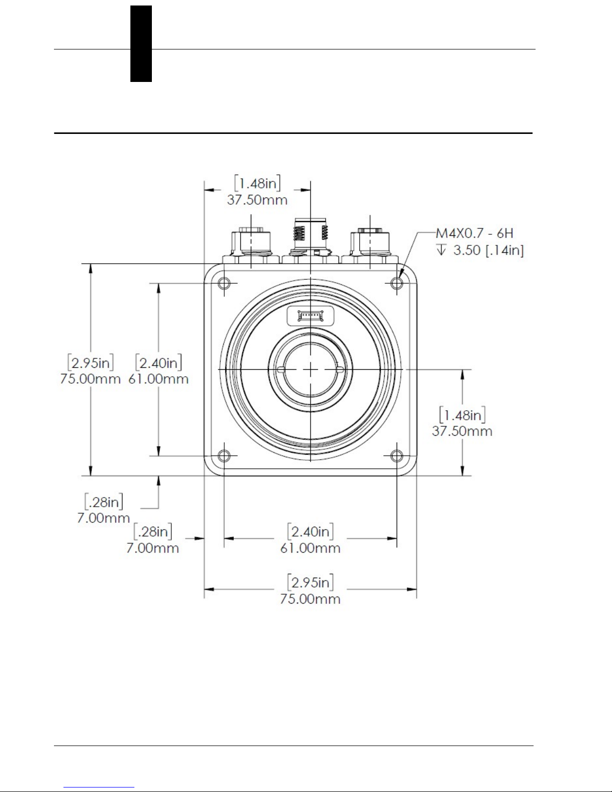
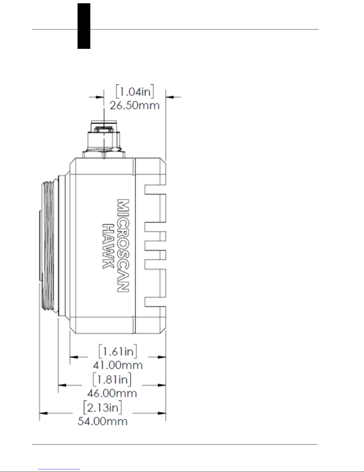
HAWK MV-4000 Dimensions
Standard HAWK MV-4000 Front
2-6 HAWK MV-4000 Smart Camera Guide
Page 21
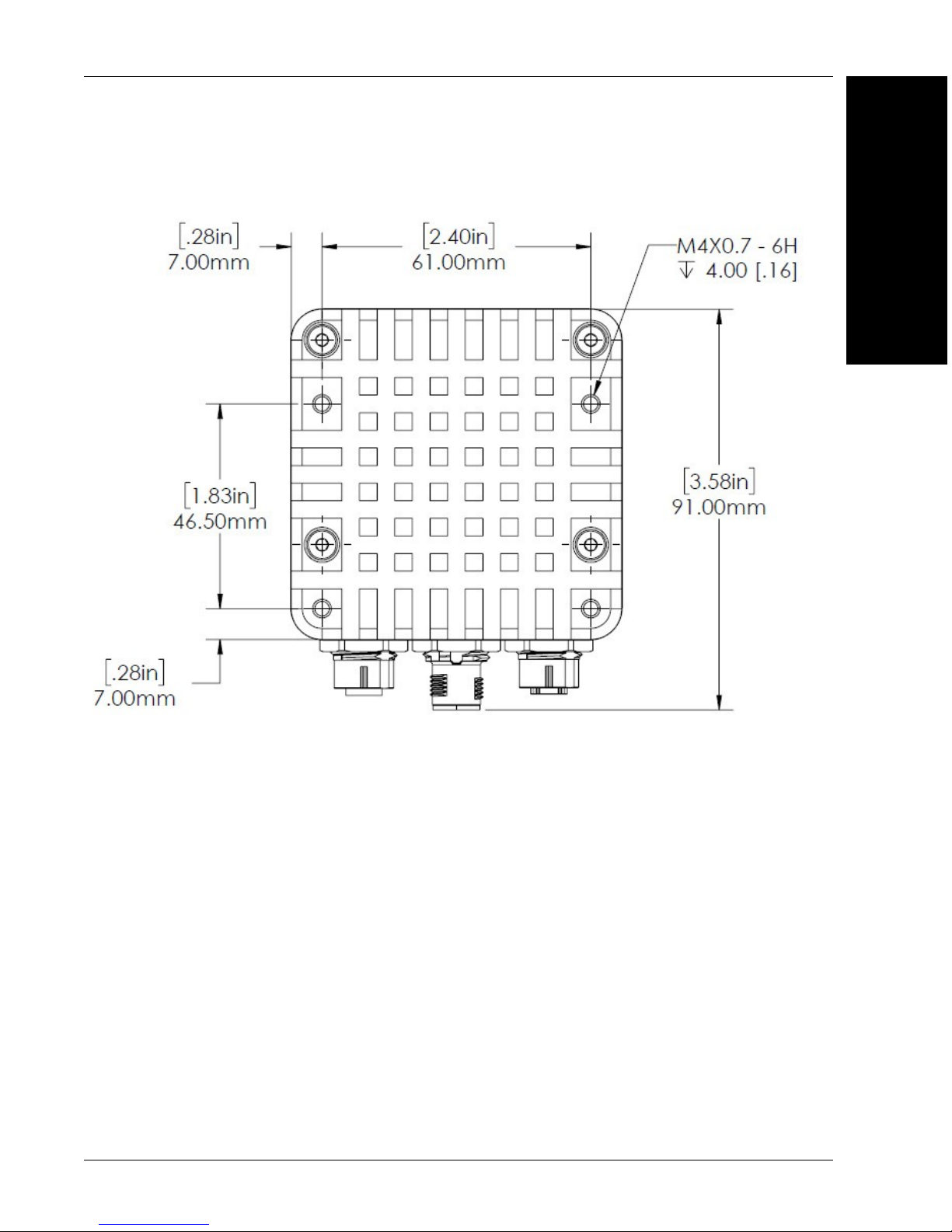
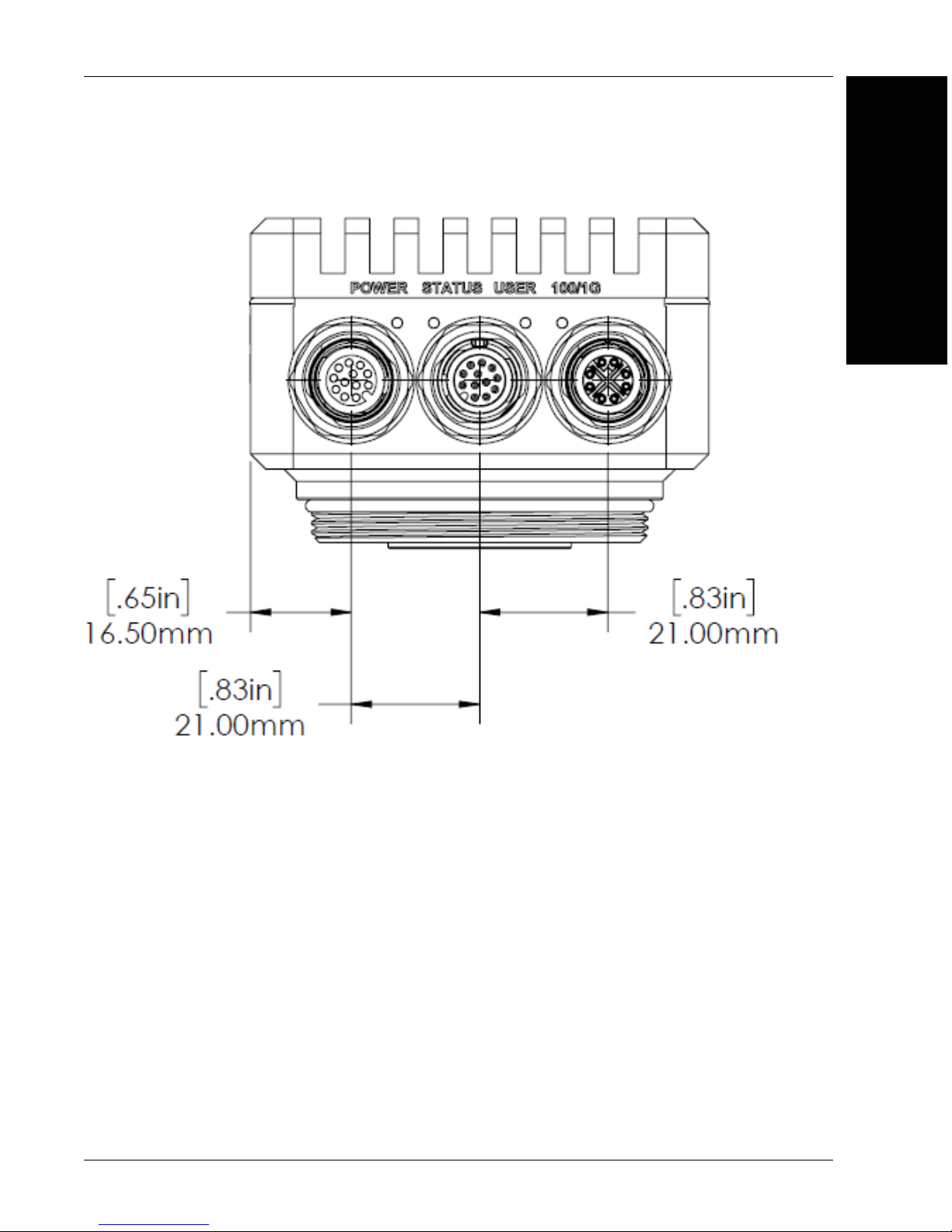
Standard HAWK MV-4000 Back
HAWK MV-4000 Dimensions
2
System Components
HAWK MV-4000 Smart Camera Guide 2-7
Page 22
Chapter 2 System Components
Standard HAWK MV-4000 Side
2-8 HAWK MV-4000 Smart Camera Guide
Page 23
Standard HAWK MV-4000 Base
HAWK MV-4000 Dimensions
2
System Components
HAWK MV-4000 Smart Camera Guide 2-9
Page 24
Chapter 2 System Components
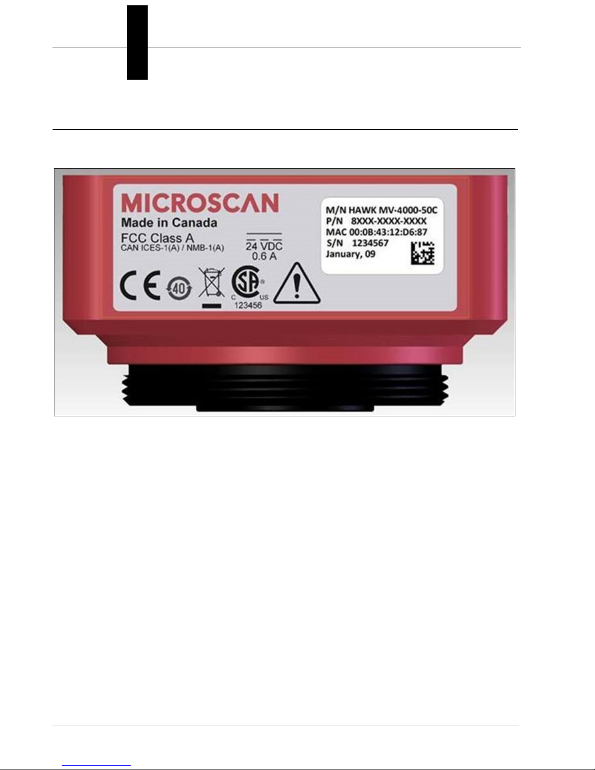
Label Information
Each HAWK MV-4000 Smart Camera has a label that contains important information about
that camera.
•M/N: The model name of the camera.
• P/N: The Microscan part number of the camera.
• MAC: The MAC address of the camera.
• S/N: The serial number of the camera.
2-10 HAWK MV-4000 Smart Camera Guide
Page 25
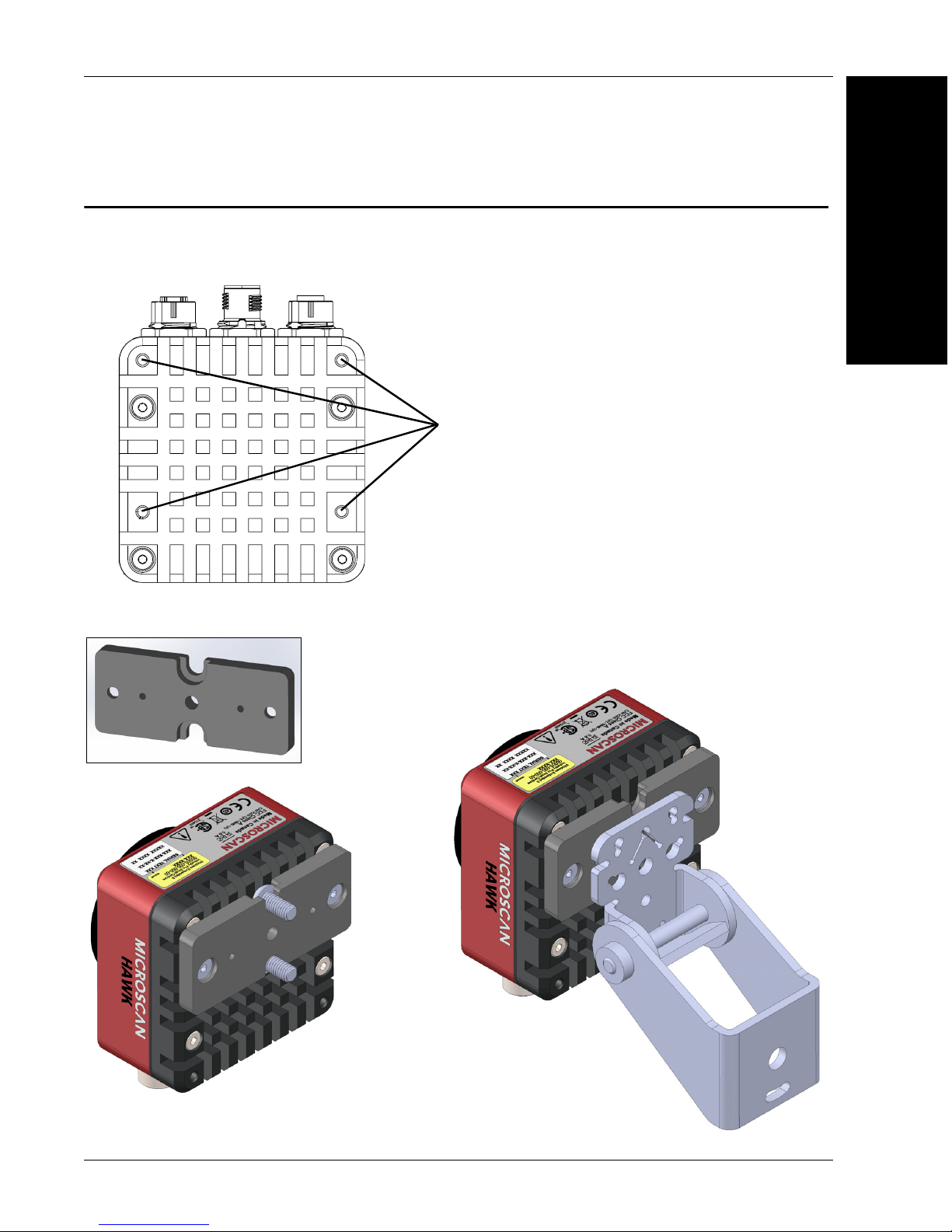
Mounting, Connecting, and Wiring
Mounting holes
(M4x0.7 thread,
4 mm deep)
¼-20 tripod
mounting hole
Mounts on standard tubing
with 6 mm hardware.
Adapter to
standard
APG mount.
Mounting, Connecting, and Wiring
Mounting the HAWK MV-4000
• Mount the camera (1) securely as required by the application.
2
System Components
Universal Mount and APG Mount
HAWK MV-4000 Smart Camera Guide 2-11
Page 26
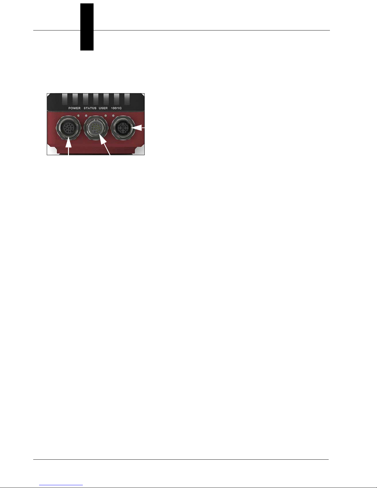
Chapter 2 System Components
100/1000Base-T
Connector
Digital I/O and
Power Connector
VGA/USB
Connector
Connecting the HAWK MV-4000
• The HAWK MV-4000 Smart Camera has the following interfaces:
• 100/1000 Base-T Connector. Provides connectivity between the HAWK MV-4000
and your computer or your network. The HAWK MV-4000 can gain access to a LAN
via Gigabit Ethernet (GigE, 1G Base-T, or 1000Base-T), fast Ethernet (100Base-T), or
twisted pair Ethernet (10Base-T).
• VGA/USB Connector. Provides connectivity between the HAWK MV-4000 and a
display device and/or USB device (such as a keyboard or a mouse).
• Digital I/O and Power Connector. Receives power from an external power source.
This connector can also receive trigger input and send/receive general auxiliary I/O
signals to/from third-party I/O devices. In addition, the connector has a specialized
analog dimmer output intended to be used with advanced Illumination lighting devices.
2-12 HAWK MV-4000 Smart Camera Guide
Page 27
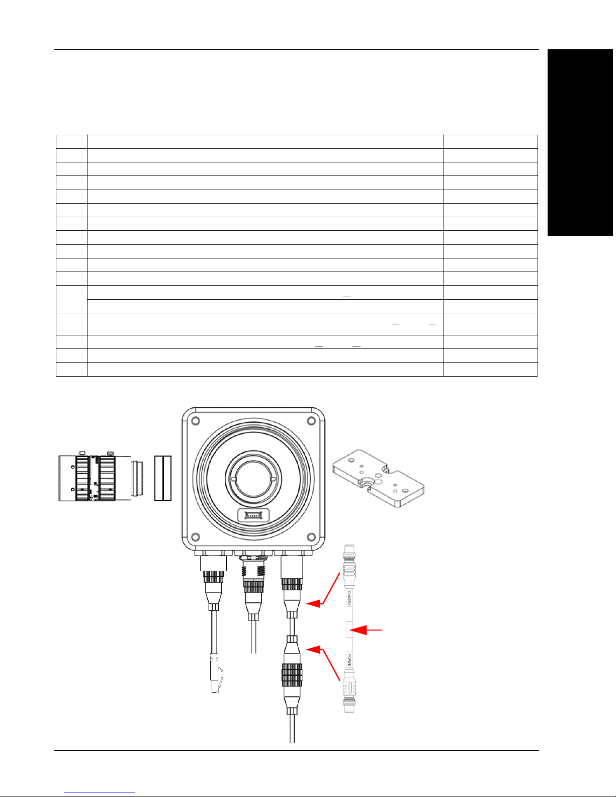
Mounting, Connecting, and Wiring
5
2
4
1
15
61-9000132-01
CAMERA End
POWER End
6
14
7
Power Supply
(12-Pin Socket)
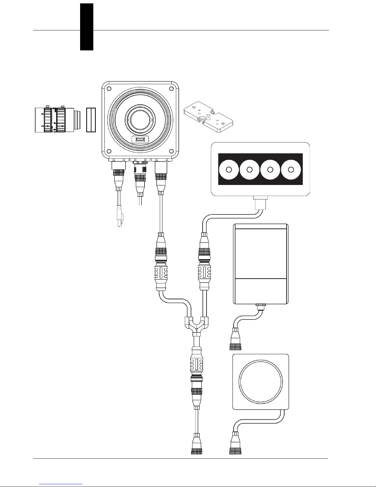
Hardware Configurations
Item Description Part Number
1 HAWK MV-4000 Smart Camera 8X1X-XXX0-010X
2 Lens, C-Mount 98-90001XX-01
3 IP67 Lens Cover for HAWK MV-4000, 50 mm or 70 mm (not shown) 98-900015X-01
4 Lens Extension Tube Set, 0.5 mm, 1 mm, 5 mm, 10 mm, 20 mm, 40 mm 98-CO206
5 Cable, HAWK MV-4000 Ethernet, X-CODE / RJ45 CAT 6A, 1 m, 3 m, or 5 m 61-9000134-0X
6 Cable, HAWK MV-4000 M12 to USB Socket or VGA / USB, 1 m 61-900014X-01
7 Cable, Adapter, HAWK MV-4000 to Accessory Cables / Power Supply (supplied with camera) 61-9000132-01
8 Cable, HAWK MV-4000 M12 to Flying Leads, 3 m (no adapter required) 61-9000151-01
9 QX Cordset, HAWK MV-4000 Adapter to QX-1 M12 Plug (Screw-On), 1 m or 3 m 61-0001XX-02
10 QX-1 Interface Device 98-000103-02
QX Photo Sensor, M12 4-Pin Plug, NPN, Dark On or Dark Off, 2 m or
11
Trigger Connector, 4-Pin Plug (Screw Terminal, Field-Wireable) (Self-Wiring) 20-610024-01
Y Cable, HAWK MV-4000 Adapter to Smart Series Illuminator and QX-1, Power or
12
Strobe, 1 m
13 Cable, QX-1 to Smart Series Illuminator, Continuous Power or
14 Power Supply, 100-240VAC, +24VDC, M12 12-Pin Socket 97-000012-01
15 APG Mount, HAWK MV-4000 (Requires Universal Mount) 98-9000054-01
On/Off or Strobe 61-0002XX-01
On/Off or
99-000020-0X
61-900013X-01
2
System Components
Standard Ethernet Configuration
HAWK MV-4000 Smart Camera Guide 2-13
Page 28
Chapter 2 System Components
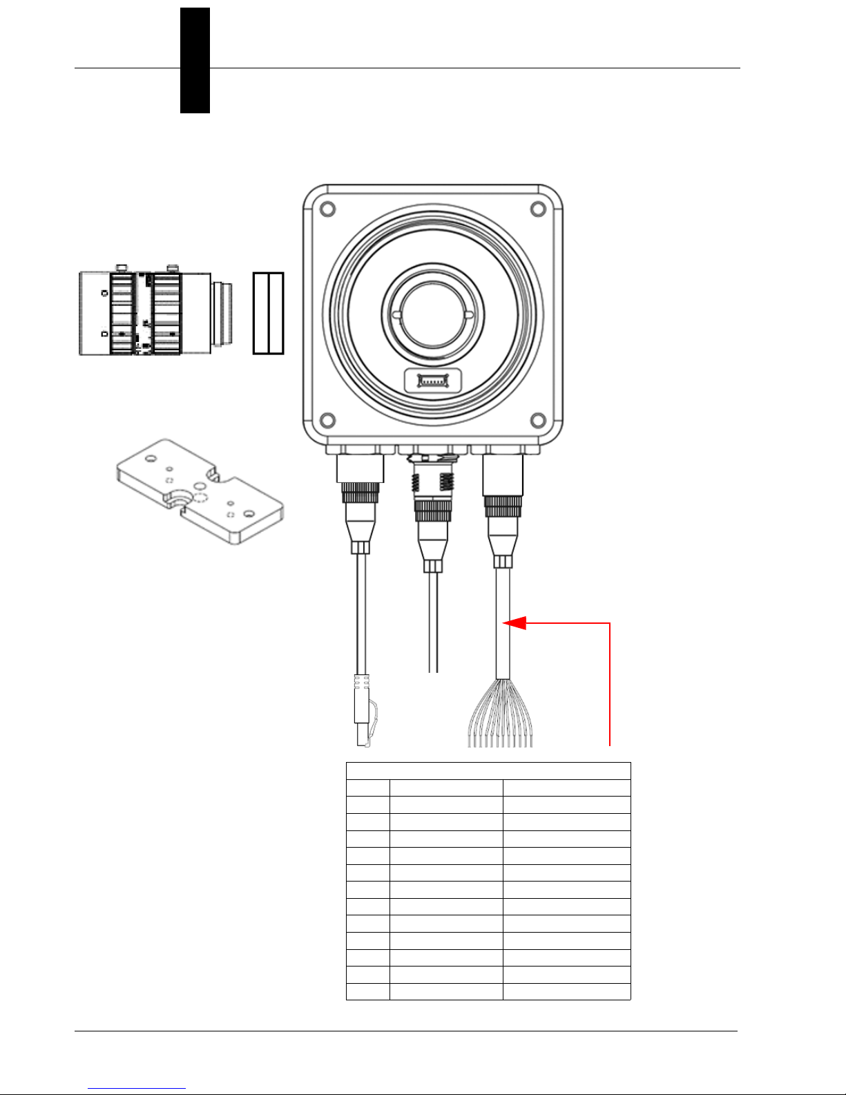
M12 to Flying Leads Cable, 3 m – 61-9000151-01
Pin Signal Wire Color
1 Output Common Red/Blue
2 Analog Output Black
3 Output 3 Pink
4 Power Brown
5 Trigger White
6 Input Common Red
7 Input 2 Green
8 Input 3 Violet
9 Input 1 Yellow
10 Output 1 Gray
11 Ground Blue
12 Output 2 Gray / Pink
5
2
4
1
15
6
8
Ethernet Configuration with Flying Leads
2-14 HAWK MV-4000 Smart Camera Guide
Page 29
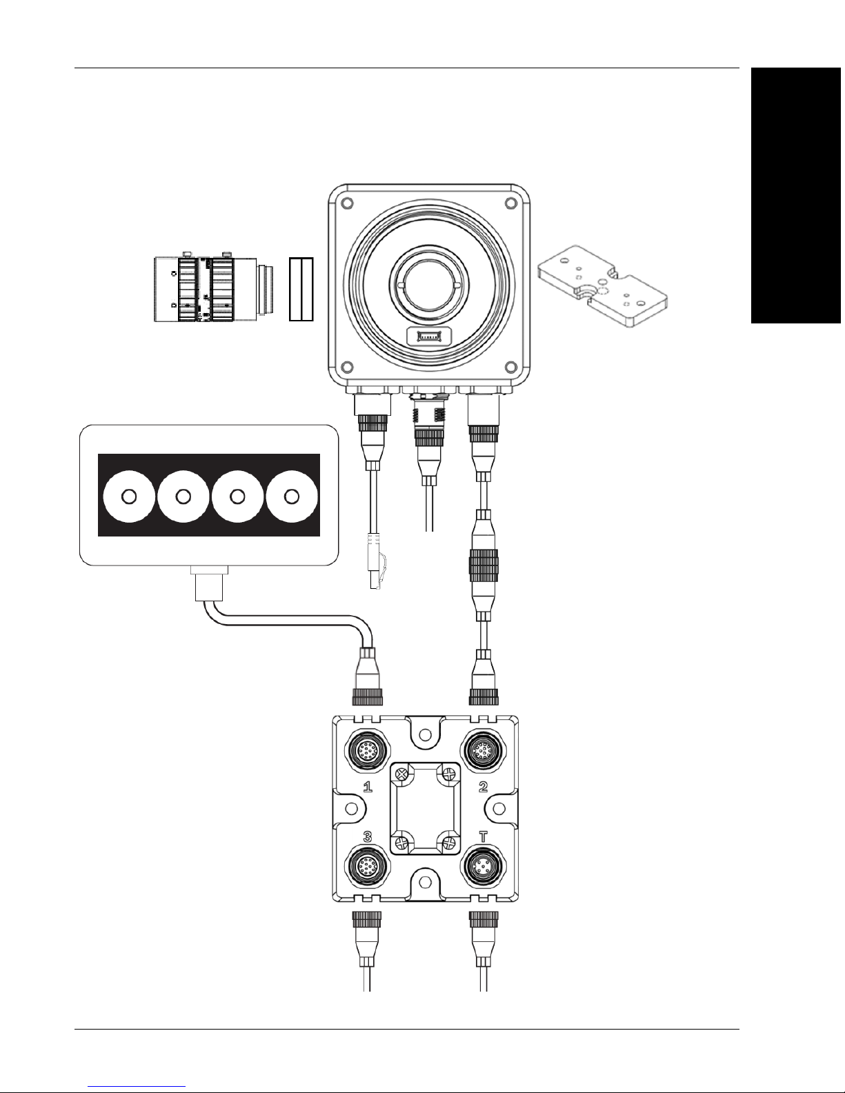
Mounting, Connecting, and Wiring
5
2
4
1
15
6
14
7
11
10
9
11
NERLITE Smart Series Illuminator
13
Power Supply
(12-Pin Socket)
Photo
Sensor
Ethernet Configuration with QX-1 and NERLITE Smart Series Illuminator
2
System Components
HAWK MV-4000 Smart Camera Guide 2-15
Page 30
Chapter 2 System Components
15
5
6
7
14
NERLITE Smart Series Illuminator
NERLITE
Smart Series
Illuminator
NERLITE
Smart Series
Illuminator
Power Supply
(12-Pin Socket)
12
2
4
1
Ethernet Configuration, Y Cable for Illuminator Control and Camera Power
2-16 HAWK MV-4000 Smart Camera Guide
Page 31

Connecting to the I/O Interface
Connecting to the I/O Interface
HAWK MV-4000 has an I/O interface with 7 optically isolated signals.
Inputs
Four of the signals are inputs. They support sinking (NPN) and sourcing (PNP)
configurations and can receive 24V. Note that sinking (NPN) or sourcing (PNP) for inputs
cannot be mixed in a system because the Input Common is shared by all Inputs.
One input is dedicated as the camera trigger (sensor). The other three are configurable
general-purpose inputs. When the HAWK MV-4000 is used with the QX-1 interface device
and photo sensor, the trigger signal is automatically connected to the correct input channel.
Input Signals:
• Trigger (Sensor)
• Input 1
• Input 2
2
System Components
• Input 3
• Input Common
Outputs
Three of the signals are outputs. They support sinking (NPN) configurations and operate
at up to 24V nominal. It is possible to connect one of the outputs in a sourcing (PNP)
configuration, but the other two outputs would no longer be available.
All three outputs are configurable for general-purpose use, but when External Strobe is
enabled in the software, Output 3 becomes dedicated to that purpose. When the HAWK
MV-4000 is used with the QX-1 interface device, or with any of the NERLITE Smart Series
lighting cables, the Strobe Output signal from the camera is automatically connected to
strobe trigger input on the Smart Series light.
Output Signals:
• Output 1
• Output 2
• Output 3 (External Strobe when Enabled)
• Output Common
HAWK MV-4000 Smart Camera Guide 2-17
Page 32

Chapter 2 System Components
Adapter Cable M12 12 Pin Plug – Power, I/O and Serial (61-9000132-01)
Note that sinking and sourcing concepts refer to the conventional current flow, which
means current flows from the positive potential towards the negative potential. A sinking
device provides a path to sink current toward ground or to the return path. A sinking device
does not provide power. A sourcing device provides a path that sources current; it
provides a path from the power source. In the following diagram, the device on the right is
the sourcing device, and the device on the left is the sinking device.
(Equivalent circuit only.)
2-18 HAWK MV-4000 Smart Camera Guide
Page 33

Connecting to the I/O Interface
Connecting Devices to Output Signals
HAWK MV-4000 output signals can be interfaced with input modules (with sourcing or
sinking input signals) found on most programmable logic controllers (PLCs) and other
devices. The output signals can also be interfaced with inductive load devices (such as a
relay, light stack or a small motor).
The HAWK MV-4000 output signals are sinking output signals, based on an NPN-type
transistor. They need to be connected to an external power source because on their own,
they are not capable of providing voltage to drive a device. They are typically connected in a
sinking configuration because they only have one dedicated pin (Output1, Output 2, Output
3 (External Strobe), respectively) and share their other pin (Output Common). So, typically, a
sourcing device is connected to their dedicated pin and the return path is connected to the
common pin. The exact connection between the output signal, the connected device, and
the power source depends on the type of device to which you connect.
2
System Components
(Equivalent circuit only.)
HAWK MV-4000 Smart Camera Guide 2-19
Page 34

Chapter 2 System Components
You can also connect a single output signal in a sourcing configuration, such that the
common pin is connected to a sinking device and the dedicated pin is connected to the
power supply. However, in this configuration, the other two output signals are not
available. The exact connection between the output signal, the connected device, and the
power source depends entirely on the type of device to which you connect.
(Equivalent circuit only.)
When an output signal is on, the circuit between its Output pin and Output Common pin is
closed, allowing current to flow from the Output pin to the Output Common pin, if the
Output pin is attached to a power source or a sourcing device. When an output signal is
off, the circuit between the Output pin and the Output Common pin is opened and no
current flows through.
Important: The power source must be provided externally.
2-20 HAWK MV-4000 Smart Camera Guide
Page 35

Connecting to the I/O Interface
Connecting to a Digital Device That Requires Two Predictable
Voltage Levels to Operate
The output signals can, therefore, only present one predictable voltage level for a given
configuration: a low voltage level in a sinking configuration or a high voltage level in a
sourcing configuration. Their other output state is, by default, floating. So, if you need to
connect to a digital device that requires two predicable voltage levels to operate, pull-up or
pull-down circuitry must be added.
2
System Components
(Equivalent circuit only.)
To add pull-up or pull-down circuitry, attach an external pull-up or pull-down resistor,
respectively. A resistance value of 3 KOhms is suggested to protect your HAWK MV-4000.
Since your HAWK MV-4000 output signals can sink up to 50 mA, use the documentation
of your input to calculate the required resistance for your external pull-up/pull-down
resistor (if necessary).
In the connections above, the pull-up circuitry causes an inversion if the input of the device
is connected to the Output pin. When the output signal is on, the circuit between its Output
pin and Output Common pin is closed, and current flows from the power source to the
Output Common pin. So the observed voltage at the Output pin will be low. Whereas,
when the output signal is off, the circuit between its Output pin and Output Common pin is
open, and current flows from the power source to the input of the device. In this state, the
current is limited by the pull-up’s resistor value.
Warning: The HAWK MV-4000 output signals are compatible with voltages up to 24 V.
However, by default, the output signals offer low resistance. When they are on (their circuit
is closed), current flows directly through them. Ensure that the circuit created between the
power source, the output signal, the connected device, and return path does not cause
more than 50 mA to flow through the signal.
HAWK MV-4000 Smart Camera Guide 2-21
Page 36

Chapter 2 System Components
As a precaution, the output signals are individually fuse-protected up to 50 mA. HAWK
MV-4000 uses resettable fuses. The fuses protect HAWK MV-4000 if you accidentally
connect their corresponding output signal to a device that sources/sinks more current than
HAWK MV-4000 can safely transmit. If more than 50 mA of current goes through your
HAWK MV-4000, the fuse will eventually trip. After disconnecting your HAWK MV-4000,
the fuse will reset only after it has sufficiently cooled.
The diagram below depicts HAWK MV-4000’s onboard fuse.
(Equivalent circuit only.)
2-22 HAWK MV-4000 Smart Camera Guide
Page 37

Connecting to the I/O Interface
Optically-Isolated Output Signals
The HAWK MV-4000 output signals are optically isolated from the power and analog
reference signal as well as from the HAWK MV-4000 input signals. They are not, however,
optically isolated from each other as they share a common pin (Output Common).
About the Connections in the Following Subsections
2
The following subsections detail how to connect the most common third-party devices to
the HAWK MV-4000 output signals. Ground is only shown in the following subsections for
reference, in case you need to reference your return path to ground.
Power, as depicted in the following diagrams, represents a nominal voltage of up to 24 V
(+/- 10%). For minimum and maximum voltage requirements, refer to the electrical
specification of the optoisolated output signals, in Appendix C: General Specifications.
System Components
HAWK MV-4000 Smart Camera Guide 2-23
Page 38

Chapter 2 System Components
Connecting an Output Signal To a Sourcing Input
Connect a HAWK MV-4000 output signal to a sourcing input, as shown below.
(Equivalent circuit only.)
Note: When connecting a resistive load sourcing device instead of an input sensing
sourcing device, the same connection would be used as displayed above.
2-24 HAWK MV-4000 Smart Camera Guide
Page 39

Connecting to the I/O Interface
Connecting an Output Signal To a Sinking Input
Connect a HAWK MV-4000 output signal to a sinking input, as shown below. In this case,
the pull-up circuitry is used to source the current to the sinking input.
2
System Components
(Equivalent circuit only.)
Important: In this configuration, the other two output signals are not available.
Note: When connecting a resistive load sinking device instead of an input sensing sinking
device, the same connection would be used as displayed above.
HAWK MV-4000 Smart Camera Guide 2-25
Page 40

Chapter 2 System Components
To avoid losing two of the available three output signals, you can connect an output signal
to a sinking input as follows. Note that, in this configuration, you will need to connect an
external pull-up resistor. Since your HAWK MV-4000 output signals can sink up to 50 mA,
use the documentation of your sinking device to calculate the required resistance for your
external pull-up resistor (if necessary).
(Equivalent circuit only.)
2-26 HAWK MV-4000 Smart Camera Guide
Page 41

Connecting to the I/O Interface
Connecting an Output Signal to an Inductive Load Input
To connect a HAWK MV-4000 output signal to an inductive load input, follow the diagram
as shown below.
An inductive load device, such as a traditional relay, requires that you use a flyback diode
to protect HAWK MV-4000 from over and under-voltage, as shown below. This diode
should be connected as close as possible to the input and voltage source of your inductive
load device.
2
System Components
(Equivalent circuit only.)
HAWK MV-4000 Smart Camera Guide 2-27
Page 42

Chapter 2 System Components
Connecting Devices to the Input Signals
HAWK MV-4000 input signals can be interfaced with a wide variety of devices (such as
proximity detectors). The HAWK MV-4000 input signals only detect when current flows
between their Input pin and Input Common pin. As such, an input signal must be
connected to a device that controls the flow of current. When current is detected, the
signal is reported as on; otherwise, it is reported as off. For information on the electrical
specifications of the on and off voltage levels, see the Electrical specifications section, in
Appendix C: General Specifications.
Each of the four available input signals has one dedicated pin (Trigger, Input 1, Input 2 and
Input 3) and shares its other pin (Input Common) with the other input signals.
You can connect the input signals in a sinking or sourcing configuration. Since the input
signals share a common pin, they must all be in a sinking configuration or all in a sourcing
configuration. The exact connection between the input signal, the connected device, and
the power source depends entirely on the type of device to which you connect. You should
essentially connect your device respecting the following:
(Equivalent circuit only.)
2-28 HAWK MV-4000 Smart Camera Guide
Page 43

Connecting to the I/O Interface
Pull-Up Circuitry
In some cases, you must add pull-up circuitry to connect an output device to an input
signal; specifically, you must attach an external pull-up resistor between the voltage
source and the Input pin.
This is required when you connect the Input Common pin to the electrical return path and
the third-party output device is in a sinking configuration. In this case, select a resistor
value that will not overcurrent the output device and instead provide just enough current
and voltage to your HAWK MV-4000 input signals, according to the electrical
specifications subsection in Appendix C: General Specifications. Note that you should use
a resistor with an appropriate power rating for your circuit.
2
System Components
(Equivalent circuit only.)
HAWK MV-4000 Smart Camera Guide 2-29
Page 44

Chapter 2 System Components
Bleeding Resistor
By default, if properly configured, the current should flow from the Input pin to the Input
Common pin (when connected to a sourcing device), or from the Input Common pin to the
Input pin (when connected to a sinking device). In some cases, the amount of current
going through the sensing circuit is insufficient for the connected output device to match its
minimum current requirement when the device is in an on or off-state, depending on the
configuration of the circuit. To boost the flowing current, connect a 2.2 kOhm external
bleeder resistor between the Input and Input Common pins. For example:
(Equivalent circuit only.)
About the Connections in the Following Subsections
The following subsections detail how to connect the most common third-party devices to
the HAWK MV-4000 input signals.
Note that HAWK MV-4000 input signals are optically isolated. Ground is only shown in the
following subsections for reference, in case you need to reference your return path to ground.
Power, as depicted in the following diagrams, represents a nominal voltage of 24 V (+/10%). For minimum and maximum voltage requirements, refer to the electrical
specification of the optoisolated input signals, in the Electrical specifications subsection in
Appendix C: General Specifications.
2-30 HAWK MV-4000 Smart Camera Guide
Page 45

Connecting to the I/O Interface
Connecting a Sourcing Output Device to an Input Signal
Connect a sourcing output device to HAWK MV-4000 input signal, as shown below.
2
System Components
(Equivalent circuit only.)
HAWK MV-4000 Smart Camera Guide 2-31
Page 46

Chapter 2 System Components
Connecting a Sinking Output Device To an Input Signal
Connect a sinking output device to a HAWK MV-4000 input signal, as shown below.
(Equivalent circuit only.)
2-32 HAWK MV-4000 Smart Camera Guide
Page 47

Connecting to the I/O Interface
Connecting a 3-Wire PNP Proximity Sensor to an Input Signal
Connect a 3-wire PNP proximity sensor to a HAWK MV-4000 input signal, as shown below.
2
System Components
(Equivalent circuit only.)
HAWK MV-4000 Smart Camera Guide 2-33
Page 48
Chapter 2 System Components
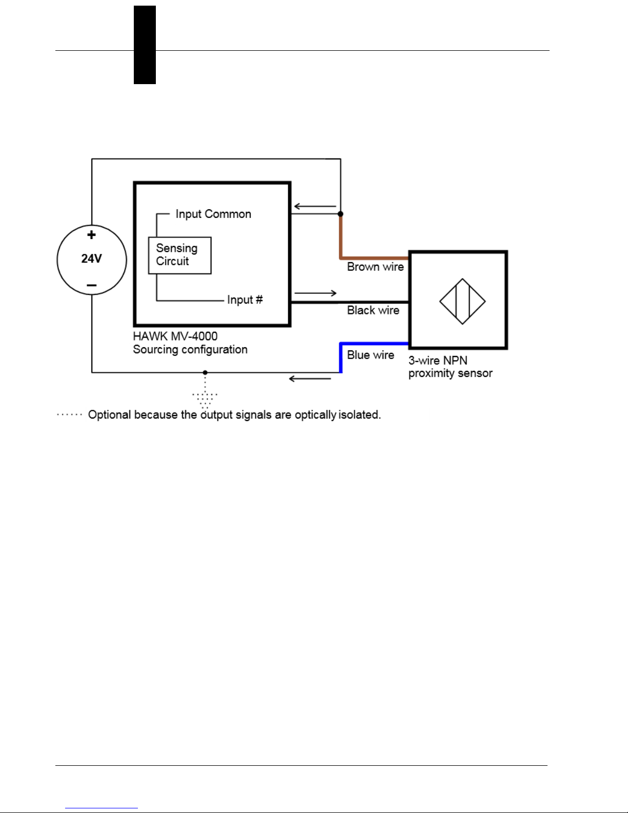
Connecting a 3-Wire NPN Proximity Sensor to an Input Signal
Connect a 3-Wire NPN proximity sensor to a HAWK MV-4000 input signal, as shown below.
(Equivalent circuit only.)
2-34 HAWK MV-4000 Smart Camera Guide
Page 49

Connecting to the I/O Interface
Connecting a 2-Wire Proximity Sensor to an Input Signal
You can connect a 2-wire proximity sensor to a HAWK MV-4000 input signal in either a
sourcing or sinking configuration (that is, on a positive or negative power wire). Note that in
both cases, you will need to install an external bleeder resistor, to ensure that a minimum
amount of current flows into the proximity sensor in its on-state and in its off- state.
For the input signal to source the current (that is, to connect an input signal on a positive
power wire), connect the 2-wire device to the input signal as shown below.
You must also install an external bleeder resistor between the Input Common pin and
brown wire of the proximity sensor.
2
System Components
(Equivalent circuit only.)
The bleeder resistor’s value should guarantee that the minimal required current is
provided to the connected sensor (the third-party device). For details regarding the
sensor’s minimum current requirements, refer to its documentation. Note that you should
use a bleeder resistor with an appropriate power rating for your circuit.
Note: You should use a resistor with an appropriate power rating for your circuit.
HAWK MV-4000 Smart Camera Guide 2-35
Page 50

Chapter 2 System Components
For the input signal to sink the current, connect the 2-wire device to input signal as shown
below. Install the external bleeder resistor between the blue wire of the proximity sensor
and the Input Common pin.
(Equivalent circuit only.)
2-36 HAWK MV-4000 Smart Camera Guide
Page 51

Input/Output Wiring Using Flying Lead Cable 61-9000151-01
M12 to Flying Leads Cable, 3 m – 61-9000151-01
Pin Signal Wire Color
1 Output Common Red/Blue
2 Analog Output Black
3 Output 3 Pink
4 Power Brown
5 Trigger White
6 Input Common Red
7 Input 2 Green
8 Input 3 Violet
9 Input 1 Yellow
10 Output 1 Gray
11 Ground Blue
12 Output 2 Gray / Pink
Input/Output Wiring Using Flying Lead Cable 61-9000151-01
2
System Components
HAWK MV-4000 Smart Camera Guide 2-37
Page 52

Chapter 2 System Components
An earth ground is provided through the cable shields and chassis of the camera.
HAWK
MV-4000
Ground and Shield Considerations
Proper grounding is necessary for operator safety, noise reduction, and the protection of
equipment from voltage transients. Buildings, including any steelwork, all circuits, and all
junction boxes must be grounded directly to an earth ground in compliance with local and
national electrical codes.
Ground Loops
Ground loops (signal degradation due to different ground potentials in communicating
devices) can be eliminated or minimized by ensuring that both the host, imager, and their
power supplies are connected to a common earth ground.
2-38 HAWK MV-4000 Smart Camera Guide
Page 53

Ground and Shield Considerations
Expected Power and Ground Connections for Proper Operation
2
System Components
Grounding Notes
• Ensure that mounting bracket “Earth” is at the same potential as power source “Earth”.
• Supply “Return” and “Earth” ground must be stable, low-impedance reference points.
• “2-Terminal Power Supply” must still provide an “Earth” connection to the imager.
• “Signal Ground” can be used for communications and/or discrete signal ground
reference. It must not be used as Power Ground or Earth Ground.
HAWK MV-4000 Smart Camera Guide 2-39
Page 54

Chapter 2 System Components
Electrical and I/O Specifications
HAWK MV-4000-03, -03C, -13, -13C, -20, -20C, -50, -50C
Operating voltage for the HAWK MV-4000 under testing conditions 24 V
Rated current 600 mA
Operating voltage tolerance ± 10%
I/O Specifications
Operating Voltage 24 V (26 V abs. max.)
Sink Current 50 mA max.
Maximum Leakage Current
Optoisolated Output Signals
ON Voltage
a
Fuse Max. Time-to-Trip
PTC
OFF-to-ON Response 2 ms to reach 4 V
ON-to-OFF Response 50 ms to reach 11 V
Operating Voltage 24 V (26 V abs. max.)
Input Current (Sink or Source) 3.5 mA max.
Optoisolated Input Signals
ON Voltage Level > 11 V
OFF Voltage Level < 4 V
OFF-to-ON Response 6 ms
ON-to-OFF Response 80 ms
Non-isolated. Supports Advanced Illumination ICS3 (inline control
0-10 V Analog Control Output Signal
system) lighting devices. Note that the 0-10 V is intended for reference
voltage only (< 1 mA).
Varioptic Caspian C-39N0-160-I2C or C-39N0-250-I2C Liquid Lens
Supplied Voltage 5 V
Typical
Rated Current 50 mA
1 mA@ 24 V
1 mA@ 26 V
0.4 V @ 2 mA
1.1 V @ 25 mA
1.5V @ 50 mA
1 sec @ 0.5 A
b
c
d
, 1 mA min.
f
e
a. The PTC is an automatically resetting fuse.
b. This occurred under the following condition: output pulled to 24 V using 1 kW.
c. Regardless of whether the signal is sinking or sourcing, this measurement is the same.
d. Maximum input current at max. ON voltage. The connected device must not limit the
current to a value lower than this.
e. Minimum input current at min. ON voltage. Can be used to calculate bleeding resistor
needed for 2-wire proximity sensor.
f. Recommended > 12 V when using HAWK MV-4000 breakout board.
2-40 HAWK MV-4000 Smart Camera Guide
Page 55

Environmental Specifications
• For indoor use only.
• Maximum altitude: 2,000 meters
Environmental Specifications
2
• Operating temperature: 0° to 50° C (32° F to 122° F)
• Ventilation requirements: Natural convection
• Pollution degree: 2 environment
• Over-voltage category: I
• Ingress protection rating: IP67
1
System Components
HAWK MV-4000 Smart Camera Guide 2-41
1. Under current testing conditions.
Page 56

Chapter 2 System Components
Status Indicators
The base of the HAWK MV-4000 Smart Camera has multiple LEDs that indicate different
power, status, user, and communication states.
The HAWK MV-4000 LEDs are:
• POWER and USER. The colors of these two LEDs change as your HAWK MV-4000
boots up.
• Status. This LED shows the general activity of your HAWK MV-4000.
• 100/1G. This LED shows the connection status of your HAWK MV-4000.
The POWER and USER LEDs typically display one of the following sets of colors:
LED Color
Power User
Off Off HAWK MV-4000 has no power.
Red Red Power is available but the HAWK MV-4000 is not responding.
Red Orange Memory initialization error detected.
Orange Orange/Red Blinking Thermal trip detected.
Orange Orange BIOS execution in progress.
Orange Green BIOS execution completing.
Green Off AutoVISION is now in control of the camera.
Green Orange Operating system startup in progress.
Green Green Camera ready.
Green Orange/Off Blinking Overheat detected. Temperature is above throttle temperature limit.
Description
2-42 HAWK MV-4000 Smart Camera Guide
Page 57

Adding a HAWK MV-4000 to a Network
Adding a HAWK MV-4000 to a Network
Corporate-wide networks typically use DHCP servers to assign each connected device an IP
address. If your HAWK MV-4000 is still in its factory-configured state, and your network uses
a DHCP server, no configuration is required to use your HAWK MV-4000 on your network.
Default Device Name
2
By default, HAWK MV-4000 comes factory configured with a unique device name. The
device is preprogrammed with a Class C static IP address: 192.168.0.100. This name is
used when connecting to a network and is of the form:
HAWK329999
The last four hexadecimal digits of your HAWK MV-4000’s MAC address are used as the
numeric part of the device name. Both the network name of your HAWK MV-4000 and its
MAC address are written on a sticker on your HAWK MV-4000. Note that, when dealing
with the Windows version, the device name is also known as the computer name.
System Components
HAWK MV-4000 Smart Camera Guide 2-43
Page 58

Chapter 2 System Components
Setting Up a Job in AutoVISION
AutoVISION is a critical component of the HAWK MV-4000’s functionality. Designed for use
with the HAWK MV-4000, AutoVISION provides an intuitive interface, step-by-step configuration,
and a library of presets that allow easy setup and deployment. For more complex vision
applications, the system can be upgraded from AutoVISION to Visionscape.
1. Mount and connect the HAWK MV-4000 hardware.
2. Plug in the power supply.
3. Select your HAWK MV-4000 in the AutoVISION Connect view, create a job, and adjust
camera settings.
AutoVISION's Connect view allows you to select your device and configure its settings,
and to create a new job. The Select Device dropdown menu provides a list of available
devices. Hover the mouse over a device to see its details.
2-44 HAWK MV-4000 Smart Camera Guide
Page 59

Setting Up a Job in AutoVISION
Note: The HAWK MV-4000’s default IP
address is: 192.168.AA.BB where
AA.BB are the last 2 octets in decimal of
the device MAC Address with subnet
Class B 255.255.0.0. Set your PC to the
same subnet (192.168.0.1, for example).
To access the camera’s “health status”,
enter the address http://[your camera
name]:8088 in a browser, where [your
camera name] is the name of the device
– HAWK3204E8, for example.
Modify camera settings in the
Details area at the left of the
Connect view. Create, Load, or
Upload a job using the buttons in
the center of the Connect view.
Important: When modifying camera settings,
you will need to enter a username and password
for the camera if a password has been defined.
Click the lock icon to take control of the camera. When you have control of the camera,
the Modify button will appear beneath the camera settings. Click the Modify button to
adjust camera settings.
2
System Components
HAWK MV-4000 Smart Camera Guide 2-45
Page 60

Chapter 2 System Components
Once you have selected your camera, adjusted its settings, and created a new job, you will
move to the Image view. This view allows you to Auto Calibrate the camera, and to manually
adjust the camera's Exposure, Gain, and Focus, and also to set the Lighting Mode (On,
Off, or Strobe).
2-46 HAWK MV-4000 Smart Camera Guide
Page 61

Setting Up a Job in AutoVISION
4. Edit the Job in AutoVISION.
After you have created a new job, loaded a job from your PC, or uploaded a job from
the camera, you will proceed to the Edit view to refine your machine vision job. The
Camera parameters below the captured image allow you to set Gain, Exposure, Focus,
Trigger, and Lighting. Inspection Outputs options allow you to connect your job to the
outside world. This is also the view where you can add multiple tools to the job. The
tool icons are located above the main view area.
2
System Components
HAWK MV-4000 Smart Camera Guide 2-47
Page 62

Chapter 2 System Components
5. Run the Job in AutoVISION.
Going to the
Run
view will automatically download your job to the camera and start it running.
6. Save the Job.
Click the Save to Camera icon on the File menu bar to save the job to the camera.
2-48 HAWK MV-4000 Smart Camera Guide
Page 63

Setting Up a Job in AutoVISION
Trigger Debounce
Trigger Debounce is the ability of the system to accommodate switching noise on a
trigger state change – a common issue with relays that have some intermittent contact
while engaging.
Trigger overruns (when the vision system is triggered faster than the device can process)
can sometimes be avoided by increasing the “debounce” time in the camera definition file
located in the C:\Microscan\Vscape\Drivers\CamDefs directory.
The IO Line Debounce High Time and IO Line Debounce Low Time can be added to the
file as in the example below. Debounce time is 100 μs.
The minimum value for "IO Line Debounce Time" is 0 µs, which disables software debounce
altogether. The maximum value is 268432 µs.
Standard debounce as described for the trigger:
IO Line Debounce High Time 100 //usecs (valid range: 0 to 268432 such that
debounce time * 1000 must be divisible by 16)
IO Line Debounce Low Time 100 //usecs (valid range: 0 to 268432 such that
debounce time * 1000 must be divisible by 16)
2
System Components
HAWK MV-4000 Smart Camera Guide 2-49
Page 64

Chapter 2 System Components
Camera Definition File Example
// Camera Definition File
// Version: 1.10
Camera Name HAWK MV-4000 752x480 CMOS // Name
Displayed in Camdef Selection Dialog
Digitizer Type 4000 // Number
associated with HAWK MV-4000 CMOS Camera
Stride 752 // Image Width
Rows 480 // Image Height
X Offset 0 // Image X Offset
Y Offset 0 // Image Y Offset
Bits Per Pixel 8 // Bits that represent Pixel Value
Pixel Type 0 // Type of Pixel:
MONOCHROME=0, COLOR_RGB=1, COLOR_BGR=2, COLOR_BAYGR8=3,
COLOR_BAYRG8=4, COLOR_BAYGB8=5, COLOR_BAYBG8=6, COLOR_HSI=7
Image Structure1 // Pixel Organization: Packed=1,
TwoPlanes = 2, ThreePlanes = 3
Async Control 1 // Controllable shutter time.
Usually using a pulse width specified in usecs
Usecs Per Frame 16667 // Fastest time to acquire a
frame: 60 FPS for HAWK MV-4000 CMOS Camera // -1 Disables timeout
feature
// IO Configuration
GPIO Edit Mask 0x0000
GPIO Defaults 0x0001 // 1 General Purpose Input 3
General Purpose Outputs
GPIO Count 4
GPIO Inputs 1
GPIO Outputs 3
Sensors 1 // One input
dedicated to Trigger signal
Strobes 0
Virtual IO 2048
IO Line Debounce High Time 100 //usecs (valid range: 0 to 268432 such that
debounce time * 1000 must be divisible by 16)
IO Line Debounce Low Time 100 //usecs (valid range: 0 to 268432 such that
debounce time * 1000 must be divisible by 16)
Custom External Strobe Delay Time 0 //usecs
// Focus & Photometry Ranges
Gain Dflt 20
Gain Min 0
Gain Max 100 // 0 to 100%
Exp Dflt 400
Exp Min 25
Exp Max 100000// 1/10 to 1/40,000
Focus Dflt 400
Focus Min 100
Focus Max 4000 // 1 to 40 inches
// Lens Configuration
C-Mount 0 // 0 = false, 1 = true
2-50 HAWK MV-4000 Smart Camera Guide
Page 65

Setting Up Partial Scan
Setting Up Partial Scan
Sensor WOI Limitations
The combination of X Offset and Y Offset determines the location of the top left corner
of the window of interest (WOI).
Stride determines the width of the WOI.
Rows determines the height of the WOI.
2
System Components
All the highlighted fields shown in the example above must be changed when creating a
partial scan camdef. The file name must also be changed, showing the WOI size in the name.
• X Offset: This value must be a multiple of 32.
• Y Offset: This value must be a multiple of 2.
• Stride: This value must be a multiple of 32.
• Rows: This value must be a multiple of 2.
Minimum size X of 32. Maximum value to whole sensor size.
Minimum size Y of 2. Maximum value to whole sensor size.
HAWK MV-4000 Smart Camera Guide 2-51
Page 66

Chapter 2 System Components
2-52 HAWK MV-4000 Smart Camera Guide
Page 67

3
CHAPTER 3 Lighting
This section describes HAWK MV-4000 Smart Camera illumination options.
3
Lighting
HAWK MV-4000 Smart Camera Guide 3-1
Page 68

Chapter 3 Lighting
Before correct lighting After correct lighting with a
NERLITE Illuminator
Illumination
The HAWK MV-4000 Smart Camera is a C-Mount camera and is used with external lighting.
Any lighting can be used, but the HAWK MV-4000 comes with accessories and cables that
allow it to connect directly with Microscan’s NERLITE Smart Series lights. Software control
allows the lights to be operated in multiple modes: Off, Continuous, and Strobe.
Machine Vision Lighting Principles
Proper lighting is critical to the success of a machine vision application. Depending on the
requirements of your application, you may need external lighting from Microscan’s
NERLITE family of machine vision lighting products.
Consider the following when setting up your application:
• Is the surface of the object flat, slightly bumpy, or very bumpy?
• Is the surface matte or shiny?
• Is the object curved or flat?
• What is the color of the object or area being inspected?
• Is the object moving or stationary?
Machine vision lighting should maximize contrast of the areas or features being inspected
while minimizing the contrast of everything else.
For more information about machine vision lighting, visit:
http://www.microscan.com/en-us/resources/know-your-tech/microscan-lighting-selector
3-2 HAWK MV-4000 Smart Camera Guide
.
Page 69

External Illumination Control and Wiring
Optics and Lighting
1
1
1
9
7
3
4
5
2
6
8
External Illumination Control and Wiring
The HAWK MV-4000 Smart Camera supports external lighting with Microscan’s NERLITE
Smart Series lights. The diagrams below demonstrate how the camera and light can be
configured with the QX-1 interface device and light kit Y-cables. The light is controlled
using the lighting control in AutoVISION Software’s camera configuration settings.
HAWK MV-4000 and Smart Series Light Configuration: QX-1
Item Description Part Number
1 Smart Series Light NER-011660XXXG
2 QX-1 Interface Device 98-000103-02
Cable, Adapter, HAWK MV-4000 to QX-1 61-9000132-01
3
4 Cordset, Common, M12 12-Pin Socket to M12 12-Pin Plug, 1 m 61-000162-02
or
Cordset, Common, M12 12-Pin Socket to M12 12-Pin Plug, 3 m 61-000148-02
5 Cable, Power, Smart Series to QX-1 61-000204-01
Power Supply, 100-240VAC, +24VDC, M12 12-Pin Socket 97-000012-01
6
7 Cordset, Host, Ethernet, M12 8-Pin Plug to RJ45, 1 m 61-9000134-0X
8 Photo Sensor, M12 4-Pin Plug, NPN, Dark On, 2 m 99-000020-02
9 HAWK MV-4000 Smart Camera
3
Lighting
In Strobe mode, the external illuminator is strobed with the exposure of the camera to
maximize light for the short exposure times needed in dynamic applications.
ON/OFF mode allows the external illuminator to be enabled and disabled using the HAWK
MV-4000’s I/O.
Control is achieved using Output 3 on the camera.
HAWK MV-4000 Smart Camera Guide 3-3
Page 70

Chapter 3 Lighting
1
1
1
3
4
5
2
6
HAWK MV-4000 and Smart Series Light Configuration: Y-Cable
Item Description Part Number
1 Smart Series Light NER-011660XXXG
2 Assembly, Cable, QX-1 to Smart Series and Camera, Power 61-9000135-01
or
or Assembly, Cable, QX-1 to Smart Series and Camera, Strobe 61-9000137-01
or Cordset, Common, M12 12-Pin Socket to M12 12-Pin Plug, 3 m 61-000148-02
Assembly, Cable, QX-1 to Smart Series and Camera, On/Off 61-9000136-01
Cordset, Common, M12 12-Pin Socket to M12 12-Pin Plug, 1 m 61-000162-02
3
Cable, Adapter, HAWK MV-4000 to QX-1 61-9000132-01
4
5 Cordset, Host, Ethernet, M12 8-Pin Plug to RJ45, 1 m 61-000134-0X
6 HAWK MV-4000 Smart Camera
3-4 HAWK MV-4000 Smart Camera Guide
Page 71

A
APPENDIX A Selecting a Lens
This section contains information about choosing the best lens to suit
your application.
A
Selecting a Lens
HAWK MV-4000 Smart Camera Guide A-1
Page 72

Appendix A Selecting a Lens
Lens Selection
This section includes information on lens selection, an important consideration when
building your application. The HAWK MV-4000 comes accessorized with a variety of lens
types and sizes to aid you in solving your application challenges.
Choosing the Correct Lens Size for the Application
The primary consideration during lens selection is that the focal length of the selected
lens meets your application’s requirements. The choice of focal length, when combined
with the sensor size, determines the field of view the camera will see at a given distance
between the front of the camera lens and the object, which is called the object distance.
A simple formula can be used to compute any of the four parameters. The formula is:
Sensor Size / Focal Length = Field of View / Object Distance
Example: The application requirement is for a 75 mm wide field of view at an object
distance of 200 mm, using the 1.3 MP sensor. What is the required focal length of the
lens? Rearrange the equation as follows:
Focal Length = Sensor Size / Field of View x Object Distance
Focal Length = 6.144 mm / 75 mm x 200 mm = 16.38 mm
The closest lens to this in the price list is 16 mm.
The sensor sizes needed for the calculation above depend on the model of your HAWK
MV-4000 Smart Camera. The sensor sizes are listed below.
Model Horizontal Sensor Size Vertical Sensor Size
HAWK MV-4000-03, MV-4000-03C 3.072 mm 2.304 mm
HAWK MV-4000-13, MV-4000-13C 6.144 mm 4.915 mm
HAWK MV-4000-20, MV-4000-20C 9.216 mm 5.760 mm
HAWK MV-4000-50, MV-4000-50C 12.442 mm 9.830 mm
A-2 HAWK MV-4000 Smart Camera Guide
Page 73

Lens Selection
Crisp Image Created with a Higher-Quality, Higher-Cost Lens Matched to Pixel Size
Blurred Image Created with a Lower-Quality, Lower-Cost Lens Not Matched to Pixel Size
Choosing the Correct Lens Quality for the Application
The secondary consideration during lens selection is lens quality. Not all lenses are
created equal. Lenses are specified in combination with the sensor pixel size to which
they are able to resolve.
The diagrams below illustrate this concept. A lower-quality, lower-cost lens will create
some blur in the image, while a higher-quality, higher-cost lens will not. The choice of lens
will depend on the application requirements.
The first of the diagrams below shows an image blur created by a lens not matched with
the pixel size. The second of the two diagrams shows a crisp image created with a lens
matched with the pixel size.
A
Selecting a Lens
The HAWK MV-4000 sensors all have a pixel size of 4.8 microns.
The standard HAWK MV-4000 comes with 3 lens types:
• The first is a standard, low-cost lens for 5 to 7 micron pixels. This lens is adequate for
most inspection and reading applications.
• The second lens type is for 3.45 micron pixels. This lens is appropriate for most
gauging and code verification applications.
• The third lens type is also for 3.45 micron pixels, but is sized for the 1” sensor type
used in the 5 MP sensor.
HAWK MV-4000 Smart Camera Guide A-3
Page 74

Appendix A Selecting a Lens
Lens Specifications
Part
Number
Standard Resolution Lens, 2/3" Sensor
98-9000167-01
98-9000168-01
98-9000169-01
98-9000170-01
98-9000171-01
98-9000172-01
High Resolution Lens 2/3" Sensor
98-9000192-01
98-9000165-01
98-9000166-01
98-9000154-01
98-9000163-01
98-9000164-01
High Resolution Lens, 1" Sensor
98-9000174-01
98-9000175-01
98-9000176-01
98-9000177-01
Autofocus Lens
98-9000178-01
98-9000179-01
IP Cover
98-9000155-01 Kit, IP Cover, 50 mm
98-9000156-01 Kit, IP Cover, 70 mm
KIT, LENS, C-MOUNT, F1.2/6MM,
1.5MP, 2/3" 50 mm 1.2 -1.84 1/2" 100 M27 x 0.5 6.5 μm
KIT, LENS, C-MOUNT, F1.4/9MM,
1.5MP, 2/3" 50 mm 1.4 -2 2/3" 100 M27 x 0.5 6.5 μm
KIT, LENS, C-MOUNT, F1.4/12.5MM,
1.5MP, 2/3" 50 mm 1.4 -1.95 2/3" 100 M25.5 x 0.5 6.5 μm
KIT, LENS, C-MOUNT, F1.4/16MM,
1.5MP, 2/3" 50 mm 1.4 -0.87 2/3" 100 M25.5 x 0.5 6.5 μm
KIT, LENS, C-MOUNT, F1.4/25MM,
1.5MP, 2/3" 50 mm 1.4 -0.19 2/3" 150 M25.5 x 0.5 6.5 μm
KIT, LENS, C-MOUNT, F1.6/35MM,
1.5MP, 2/3" 50 mm 1.6 0.1 2/3" 250 M25.5 x 0.5 6.5 μm
KIT, LENS, C-MOUNT, F1.9/6MM,
5MP, 2/3" 70 mm 1.9 -2.88 2/3" 100 M37.5 x 0.5 4 μm
KIT, LENS, C-MOUNT, F1.6/8MM,
5MP, 2/3" 70 mm 1.6 -1.99 2/3" 100 M25.5 x 0.5 4 μm
KIT, LENS, C-MOUNT, F1.6/12MM,
5MP, 2/3" 70 mm 1.6 -1.26 2/3" 100 M25.5 x 0.5 4 μm
KIT, LENS, C-MOUNT, F1.6/16MM,
5MP, 2/3" 70 mm 1.6 -0.6 2/3" 100 M25.5 x 0.5 4 μm
KIT, LENS, C-MOUNT, F1.9/35MM,
5MP, 2/3" 70 mm 1.9 0.1 2/3" 200 M25.5 x 0.5 4 μm
KIT, LENS, C-MOUNT, F1.6/25MM,
5MP, 2/3" 70 mm 1.6 -0.07 2/3" 100 M25.5 x 0.5 4 μm
KIT, LENS, C-MOUNT, F1.4/12.5MM,
9MP, 1" No cap 1.4 -0.39 1" 100 M40.5 x 0.5 3.5 μm
KIT, LENS, C-MOUNT, F1.4/16MM,
9MP, 1" 70 mm 1.4 -0.458 1" 100 M40.5 x 0.5 3.5 μm
KIT, LENS, C-MOUNT, F1.4/25MM,
9MP, 1" 70 mm 1.4 -0.037 1" 100 M40.5 x 0.5 3.5 μm
KIT, LENS, C-MOUNT, F1.4/35MM,
9MP, 1" 70 mm 1.4 -0.286 1" 150 M40.5 x 0.5 3.5 μm
KIT, LENS, LIQUID, C-MOUNT,
F4/25MM, 2/3", I2C INTERFACE 50 mm 4.0
KIT, LENS, LIQUID, C-MOUNT,
F2.8/16MM, 2/3", I2C INTERFACE 50 mm 2.8
Description
IP
Cover
Aperture
TV
Distortion
(%)
Sensor
2/3" 120
2/3" 110
Closest
Focus
(mm)
Filter
Thread
Pixel
Size
Rating
A-4 HAWK MV-4000 Smart Camera Guide
Page 75

B
APPENDIX B Cable Specifications
This section contains information about HAWK MV-4000 Smart Camera
cables.
B
Cable Specifications
Note: Cable specifications are published for information only. Microscan
does not guarantee the performance or quality of cables provided by
other suppliers.
Part Number Description
61-9000132-01 Cable, Adapter, HAWK MV-4000 to QX-1
61-9000134-01
61-9000134-02
61-9000134-03
61-9000135-01
61-9000136-01
61-9000137-01
61-9000143-01
61-9000147-01
97-000012-01
99-000020-02
Cable, Ethernet, X-Code/RJ45 CAT 6A, 1 m
Cable, Ethernet, X-Code/RJ45 CAT 6A, 3 m
Cable, Ethernet, X-Code/RJ45 CAT 6A, 5 m
Cable, M12 to Smart Series and Camera, Power, 1 m
Cable, M12 to Smart Series and Camera, On/Off, 1 m
Cable, M12 to Smart Series and Camera, Strobe, 1 m
Cable, M12 to USB Socket, 1 m
Cable, M12 to VGA and USB Socket, 1 m
Power Supply, M12 12-Pin Socket, 1.3 m
Trigger, M12 4-Pin Plug, NPN, Dark On, 2 m
HAWK MV-4000 Smart Camera Guide B-1
Page 76

Appendix B Cable Specifications
HAWK MV-4000 Cables
61-9000132-01 Cable, Adapter, HAWK MV-4000 to QX-1
The 61-9000132-01 Cable, Adapter, HAWK MV-4000 to QX-1 allows the HAWK MV-4000
to be connected to the QX-1 accessory and any Microhawk M12 accessory cables. The
cable is directional and must be connected as labeled for proper function and to avoid
potential damage to the camera.
B-2 HAWK MV-4000 Smart Camera Guide
Page 77

HAWK MV-4000 Cables
61-9000134-0X Cable, Ethernet, X-Code/RJ45 CAT 6A, 1 m, 3 m, 5 m
The 61-9000134-01, -02, and -03 Cable, Ethernet, X-Code/RJ45 CAT 6A, 1m, 3m, 5m,
respectively has an X-Code M12 Ethernet connector on one end and standard RJ45 on
the other.
B
Cable Specifications
HAWK MV-4000 Smart Camera Guide B-3
Page 78

Appendix B Cable Specifications
M12-to-Smart Series and Camera Cables
There are three M12 to Smart Series and Camera cables which allow a light to be
connected to the camera without the need of the QX-1:
• 61-9000135-01 Cable, M12 to Smart Series and Camera, Power, 1 m
• 61-9000136-01 Cable, M12 to Smart Series and Camera, On/Off, 1 m
• 61-9000137-01 Cable, M12 to Smart Series and Camera, Strobe, 1 m
The M12 connector on the input side can then be connected directly to a flying leads cable
or other control device.
B-4 HAWK MV-4000 Smart Camera Guide
Page 79

HAWK MV-4000 Cables
M12 12-Pin Socket
97-000012-01 Power Supply, M12 12-Pin Socket, 1.3 m
The 97-000012-01 Power Supply, M12 12-pin Socket, 1.3 m is a 90-254 VAC, +24VDC
power supply.
B
Cable Specifications
HAWK MV-4000 Smart Camera Guide B-5
Page 80

Appendix B Cable Specifications
99-000020-02 Schematic
99-000020-02 Trigger, M12 4-Pin Plug, NPN, Dark On, 2 m
The 99-000020-02 Trigger, M12 4-pin Plug, NPN, Dark On, 2 m is a photo sensor with a
4-pin M12 connector.
B-6 HAWK MV-4000 Smart Camera Guide
Page 81

C
APPENDIX C General Specifications
This section contains specifications for the HAWK MV-4000 Smart Camera.
C
General
Specifications
HAWK MV-4000 Smart Camera Guide C-1
Page 82

Appendix C General Specifications
HAWK MV-4000 General Specifications
Sensor Board
Specifications
Geometry 1/4”-Type 1/2”-Type
CMOS Sensor
Effective Resolution (H x V) 640 x 480 1280 x 1024
Frame Rate
Pixel Size (H x V) 4.8 μm x 4.8 μm
Gain Range 0 to 19.4 dB
Exposure Speeds 50 msec to 4 sec
External Trigger Latency
(Typical value from OFF to ON)
External Trigger to Output Strobe Delay
(Typical value from OFF to ON)
Specifications
CMOS Sensor
Effective Resolution (H x V) 1920 x 1200 2592 x 2048
Frame Rate
Pixel Size (H x V) 4.8 μm x 4.8 μm
Gain Range 0 to 19.4 dB
Exposure Speeds 50 msec to 4 sec
External Trigger Latency
(Typical value from OFF to ON)
External Trigger to Output Strobe Delay
(Typical value from OFF to ON)
a
a
Format Monochrome Color Monochrome Color
Make and Model ON Semiconductor – Python Family (NOIP1SN or NOIP1SE)
a. Frame rate is established solely upon rates of acquisition. Your results will differ when including
processing time.
b. Note that these numbers come from tests that store the grabbed images in BGR packed format. When
using YUV, planar, or Mono10 packed formats, the frame rate can be significantly different.
Geometry 2/3”-Type 1”-Type
Format Monochrome Color Monochrome Color
Make and Model ON Semiconductor – Python Family (NOIP1SN or NOIP1SE)
HAWK
MV- 4000-03
Up to 293 FPS Up to 147 FPS Up to 85 FPS Up to 35 FPS
7.1 μs7.2 μs
9.1 μs9.2 μs
HAWK
MV- 4000-20
Up to 45 FPS Up to 20 FPS Up to 21 FPS Up to 8.5 FPS
8.0 μs8.0 μs
10 μs10 μs
HAWK
MV- 4000-03C
HAWK
MV- 4000-20C
HAWK
MV- 4000-13
HAWK
MV- 4000-50
HAWK
MV- 4000-13C
b
HAWK
MV- 4000-50C
b
a. Frame rate is established solely upon rates of acquisition. Your results will differ when including
processing time.
b. Note that these numbers come from tests that store the grabbed images in BGR packed format. When
using YUV, planar, or Mono10 packed formats, the frame rate can be significantly different.
C-2 HAWK MV-4000 Smart Camera Guide
Page 83

HAWK MV-4000 General Specifications
CPU Board
The CPU board of HWK MV-4000 has the following features:
• SOC/CPU: Intel Celeron Processor N2807
• Volatile Memory: 2048 Mbytes of DDR3L SDRAM
• Non-Volatile Memory: 32 GB of flash disk (eMMC) memory
• Networking: One 100/1000 Mbits (or 100 Mbit/1 Gbit) Ethernet networking interface
• An advanced I/O engine that includes the following:
– Digital I/O: 4 inputs and 3 outputs.
• Four independent, Optoisolated, digital auxiliary input signals.
Input signals have interrupt generation capabilities.
The input signals are debounced (that is, configured to wait a given amount of
time between accepting a signal change). The debouncing time can be
configured using AutoVISION. For more information, refer to the AutoVISION
online help.
The input signals can sink or source. To source voltage, you must connect an
voltage source to the common input signal (Input 3). For voltage expectations,
see Electrical Specifications subsection of the HAWK MV-4000 specifications
section, later in this appendix. Whether all the input signals are sinking or
sourcing is dependent upon the connection of the common input signal.
C
General
Specifications
• Three optoisolated output signals, used to connect devices (up to 24 V). Note
that these output signals are sinking signals that share a common signal. If
one of these signals is used as a sourcing signal, the other two are no longer
available.
• Display: Your HAWK MV-4000 provides a VGA/USB output to connect a monitor,
keyboard, and mouse directly to the device or connect a touch display to the device.
Note that a standard USB keyboard and mouse are supported natively. To connect
any other device (such as a specialized keyboard or touch screen) to your HAWK
MV-4000, it may require a specialized device driver. If the device has a third-partyprovided driver, inquire whether a specialized device driver is necessary and/or
available for your HAWK MV-4000 by contacting your local Microscan representative.
HAWK MV-4000 Smart Camera Guide C-3
Page 84

Appendix C General Specifications
VGA/USB Port
The following information relates to the device that can be connected to the VGA/USB port.
• Output: RGB analog output.
• Maximum supported resolution: 1920 x 1200.
• Maximum pixel depth: 32-bits.
• Maximum vertical refresh frequency: 60 Hz - 85 Hz, depending on resolution.
Lenses
Keep the lens free of fingerprints and dust. Do not clean with an alcohol-based cleaning
solution and do not spray water or cleaning fluids directly onto the lens. Instead, use a can
of compressed air or a lens cleaning cloth to remove dust.
The HAWK MV-4000 works with the Varioptic Caspian C-39N0-160-I2C or C-39N0-250I2C lens (liquid lens). This electronically focus-controllable C-mount lens fits within the
optional IP lens case. The Varioptic lens connects to the liquid lens connector inside the
lens case housing of your HAWK MV-4000.
General Care and Cleaning
To clean the unit housing, use a small amount of mild detergent cleaner on a cleaning
cloth. Do not pour the cleaner directly onto the unit housing.
To remove dust from the lens cap, use either a can of compressed air or a lens cloth. The
air must be free of oil, moisture and other contaminants that could remain on the lens cap.
To clean the glass window of the lens cap, use a small amount of isopropyl alcohol on a
cleaning cloth. Do not pour the alcohol directly on the glass window.
C-4 HAWK MV-4000 Smart Camera Guide
Page 85

HAWK MV-4000 General Specifications
Electrical Specifications
HAWK MV-4000-03, -03C, -13, -13C, -20, -20C, -50, -50C
Operating voltage for the HAWK MV-4000 under testing conditions 24 V
Rated current 600 mA
Operating voltage tolerance ± 10%
I/O Specifications
Operating Voltage 24 V (26 V abs. max.)
Sink Current 50 mA max.
1 mA@ 24 V
Maximum Leakage Current
Optoisolated Output Signals
ON Voltage
a
PTC
Fuse Max. Time-to-Trip
OFF-to-ON Response 2 ms to reach 4 V
ON-to-OFF Response 50 ms to reach 11 V
Operating Voltage 24 V (26 V abs. max.)
Input Current (Sink or Source) 3.5 mA max.
Optoisolated Input Signals
0-10 V Analog Control Output Signal
Varioptic Caspian C-39N0-160-I2C or C-39N0-250-I2C Liquid Lens
Typical
ON Voltage Level > 11 V
OFF Voltage Level < 4 V
OFF-to-ON Response 6 ms
ON-to-OFF Response 80 ms
Non-isolated. Note that the 0-10 V is intended for reference voltage only (< 1 mA).
Supplied Voltage 5 V
Rated Current 50 mA
1 mA@ 26 V
0.4 V @ 2 mA
1.1 V @ 25 mA
1.5V @ 50 mA
1 sec @ 0.5 A
f
b
c
d
, 1 mA min.
C
General
Specifications
e
a. The PTC is an automatically resetting fuse.
b. This occurred under the following condition: output pulled to 24 V using 1 kW.
c. Regardless of whether the signal is sinking or sourcing, this measurement is the same.
d. Maximum input current at max. ON voltage. The connected device must not limit the current to a value
lower than this.
e. Minimum input current at min. ON voltage. Can be used to calculate bleeding resistor needed for 2-wire
proximity sensor.
f. Recommended > 12 V when using HAWK MV-4000 breakout board.
HAWK MV-4000 Smart Camera Guide C-5
Page 86

Appendix C General Specifications
Environmental Specifications
• For indoor use only.
• Maximum altitude: 2,000 meters
• Operating temperature: 0° to 50° C (32° F to 122° F)
• Ventilation requirements: Natural convection
• Pollution degree: 2 environment
• Over-voltage category: I
• Ingress protection rating: IP67
Mechanical Specifications
HAWK MV-4000-03, -03C, -13, -13C, -20, -20C, -50, -50C
M12 8-pin connector for 100/1000 Base-T Ethernet.
Connectors
Certification IP67
M12 12-pin plug connector for VGA/USB.
M12 12-pin socket connector for digital I/O and power.
1
C-6 HAWK MV-4000 Smart Camera Guide
1. Under current testing conditions.
Page 87

HAWK MV-4000 General Specifications
Front
Back
Side
Base
Dimensions
Dimensions HAWK MV-4000-03, -03C, -13, -13C, -20, -20C, -50, -50C
Weight 460.39 g (16.24 oz)
Length (without connectors) 75 mm (2.95") x 75 mm (2.9"‘) ± 2 mm (0.079")
Height (without lens) 54 mm (2.13") ± 2 mm (0.079")
Width 75 mm (2.95") ± 2 mm (0.079")
C
General
Specifications
HAWK MV-4000 Smart Camera Guide C-7
Page 88

Appendix C General Specifications
HAWK MV-4000 Connectors
The HAWK MV-4000 has several interface connectors. These are the digital I/O and power
connector, 100/1000 Base-T connector, the VGA/USB connector, and the liquid lens connector.
Digital I/O and Power Adapter Cable Connector
The digital I/O and power connector of the adapter cable is an M12 12-pin plug connector
that transmits and receives digital I/O signals, provides an analog reference voltage for an
inline control system lighting controller, and provides power to your HAWK MV-4000.
C-8 HAWK MV-4000 Smart Camera Guide
Page 89

HAWK MV-4000 General Specifications
The pinout for the digital I/O and power connector adapter cable is as follows:
Pin Signal Name
1 Output Common
2 Analog Output
3 Output 3
4 Power
5 Trigger
6 Input Common
7 Input 2
8 Input 3
9 Input 1
10 Output 1
11 Ground
12 Output 2
To interface with this adapter cable connector, you can use either a Microscan accessory
cable or you can build your own. To build your own digital I/O and power cable, parts can
be purchased from:
C
General
Specifications
Cable Information
Manufacturer Phoenix Contact GmbH and Co. KG
Part Number SAC-12P- MS/3.0-PVC SC0 Order No: 1554788
Description Sensor/Actuator Cable, 12-Pos., Black PVC, Straight M12 SPEEDCON Plug on Free Conductor End, 3.0 m
HAWK MV-4000 Smart Camera Guide C-9
Page 90

Appendix C General Specifications
100/1000 Base-T Connector
The 100/1000 Base-T connector is an M12 socket 8-pin X-coded connector that provides
communication capabilities at 10 Mbit/sec, 100 Mbit/sec, or 1 Gbit/sec (1000 Mbit/sec).
The pinout for the Ethernet connector is as follows:
Pin Signal Name Description
1 MDI_1+ Bidirectional data A+
2 MDI_1– Bidirectional data A–
3 MDI_2+ Bidirectional data B+
4 MDI_2– Bidirectional data B–
5 MDI_4+ Bidirectional data D+
6 MDI_4– Bidirectional data D–
7 MDI_3– Bidirectional data C–
8 MDI_3+ Bidirectional data C+
To interface with this connector, you can use either a Microscan accessory cable or you
can purchase a similar cable from an alternate source. For an alternate source of
100/1000 Base-T cables, contact:
Cable Information
Manufacturer Phoenix Contact GmbH and Co. KG
Part Number NBC-MSX/5.0-94F/R4AC SCO Order No.: 1407473
Description
C-10 HAWK MV-4000 Smart Camera Guide
Assembled Ethernet Cable, CAT6A, 8-Position, PUR, RAL 5021 (Water Blue), Plug Straight M12
SPEEDCON / IP67, Coding: X, ON Plug Straight RJ45 / IP20, 5 m
Page 91

HAWK MV-4000 General Specifications
VGA/USB Connector
The VGA/USB connector is an M12 12-pin plug connector that transmits output video and
can both transmit and receive USB signals. The output video signal is a standard RGB
analog video output used to send the operating system’s desktop to the connected display
device. The video output can be used to display the desktop.
The table below summarizes the supported standard display resolutions:
C
General
Specifications
Standard Display Resolution Analog Video Maximum Refresh Rate
1920 x 1200 RGB 60 Hz
1920 x 1080 RGB 60 Hz
1600 x 1200 RGB 60 Hz
1280 x 1024 RGB 85 Hz
1024 x 768 RGB 85 Hz
800 x 600 RGB 85 Hz
640 x 480 RGB 85 Hz
The pinout for the VGA/USB connector is as follows:
Pin Signal Name Description
1 USB PWR 5 V supplied from your HAWK MV-4000 to USB peripherals.
2 USB_DATA_P USB data +
3 USB_DATA_N USB data –
4 USB_REF USB reference
5 RED_VID_OUT R component of the RGB video output signal
6 BLUE_VID_OUT B component of the RGB video output signal
7 VSYNC Vertical sync of the RGB video output signal
8 HSYNCH Horizontal sync of the RGB video output signal
9 GREEN_VID_OUT G component of the RGB video output signal
10 VGA _REF VGA reference
11 VGA _REF VGA reference
12 VGA _REF VGA reference
HAWK MV-4000 Smart Camera Guide C-11
Page 92

Appendix C General Specifications
The following is a wire-diagram of the VGA/USB cable, showing the connection between
the HAWK MV-4000 VGA/USB connector on one end and the HD-15 and USB connectors
on the other.
This cable can be purchased separately from Microscan (61-9000147-01). A USB only
cable (no VGA connector) can also be purchased from Microscan (61-9000143-01).
C-12 HAWK MV-4000 Smart Camera Guide
Page 93

HAWK MV-4000 General Specifications
Liquid Lens Connector
The liquid lens connector is a 6-pin shrouded connector designed to receive a 6-pin
connector from a Varioptic Caspian C-39N0-160-I2C or C-39N0-250-I2C lens. The
secondary, 3-pin plug connector from the Varioptic lens is not used.
This connector is located inside the lens cap housing of the HAWK MV-4000.
The pinout for the liquid lens connector is as follows:
Pin Signal Name Description
1 PWR Power supply (+5 V)
2 GND Ground
3 SDI Serial data line signal
4 SCK Serial data clock signal
5 Unused Unused
6 Unused Unused
C
General
Specifications
HAWK MV-4000 Smart Camera Guide C-13
Page 94

Appendix C General Specifications
C-14 HAWK MV-4000 Smart Camera Guide
Page 95

D
APPENDIX D MVMonitor Web Page
This section explains how to connect to the MVMonitor web page and
how to interpret the information displayed there.
D
MVMonitor Web Page
HAWK MV-4000 Smart Camera Guide D-1
Page 96

Appendix D MVMonitor Web Page
Using the MVMonitor Web Page
The HAWK MV-4000 Smart Camera provides a “health status” web page that can be
viewed in a web browser of your choice. General information about the camera’s network
identity and the state of the runtime is provided. To connect to the page, simply enter the
name of your camera at the specific port 8088. For example, if your camera is named
HAWK3204ce, you would connect to its web page in your browser by entering this in the
address bar:
http://hawk3204ce:8088
The web page will look similar to this:
See the next page for descriptions of the information shown above.
D-2 HAWK MV-4000 Smart Camera Guide
Page 97

MVMonitor Web Page
Top Bar
The area at the top of the page displays the following:
• Name of the camera.
• State: This shows the state of the runtime. If it is up and running, it will show
and date of
• Job: This shows the name of the .avp job file that is currently loaded (if any),
sh
ow whether the .avp is running or stopped.
when it was launched. If it is not running, it will display an error message.
the time
and will
Device Info Area
This grid is intended to provide the following basic information about the camera:
• Runtime Version: The version number of the installed machine vision ru
firm
ware.
• MAC address of the camera.
• Serial Number of the camera.
• IP Address of the camera.
• Subnet of the camera.
• DHCP: Indicates whether DHCP is on or off.
• Licenses: Lists the licenses that are currently loaded on the camera.
• Logs Count: Gives a count of the number of log files that have been created in th
\Vsc
apeRuntime\Logs folder.
• "Access Log Files" Link: Clicking this link will take you to an FTP page where yo
can
download any of the log files to your local PC.
ntime
D
MVMonitor Web Page
e
u
Launch CloudLink
Clicking Launch CloudLink opens the HAWK MV-4000 Smart Camera’s web-based runtime
monitoring interface in a separate browser tab. More information about CloudLink can be
found in Appendix E: CloudLink Web HMI.
Job Info Area
• Name: Name of the currently loaded job.
• Last Saved Date: Date and time when the job was last saved.
• Downloaded From: Name of the host from which the job was downloaded.
• Download Dir: Name of the directory on the host from which the job wa
wnloaded.
do
s
Refreshing the Page
The data displayed when you first see the MVMonitor page is only what has been captured
at the time the page is loaded. The page does not self-refresh automatically, so if the job
changes, or the state of the device changes, that new information will not be reflected on
the MVMonitor web page unless you manually refresh it.
HAWK MV-4000 Smart Camera Guide D-3
Page 98

Appendix D MVMonitor Web Page
D-4 HAWK MV-4000 Smart Camera Guide
Page 99

E
APPENDIX E CloudLink Web HMI
CloudLink allows you to visualize Microscan Link values and images
from compatible Microscan smart cameras and vision systems. It runs in
your web browser, and is compatible with a wide variety of modern
browsers including those found on tablets and smart phones.
E
CloudLink Web HMI
This appendix contains information about CloudLink support for the
HAWK MV-4000. Refer to Getting Started with CloudLink – installed in the
documentation folder C:\Microscan\Vscape\Documentation during
AutoVISION/Visionscape installation – for detailed information about
configuring and using the CloudLink web HMI.
CloudLink supports Windows 7 (32-bit and 64-bit) and Windows 10.
CloudLink requires an HTML5-compatible browser:
• Internet Explorer 11 or later
• Google Chrome
• Firefox
• Mobile Safari (iPhone / iPad)
• Mobile Chrome on Android devices
The following browsers were explicitly tested for compatibility:
• Internet Explorer 11.0.2
• Google Chrome 33.0
• Firefox 28.0
Additional Notes:
• Safari for Windows is not supported.
• Internet Explorer 11 or later and Google Chrome 33 or later are
recommended for extended CloudLink sessions.
HAWK MV-4000 Smart Camera Guide E-1
Page 100

Appendix E CloudLink Web HMI
If using a HAWK MV-4000, you can also type the name of the device, as in the example
http://HAWK5E7420
.
Click the CloudLink Dashboard
icon to launch the application.
Connecting
To launch CloudLink, use your favorite web browser and enter the address of your device
in the browser’s address bar. For example, if you have a Microscan smart camera on your
network at address 10.20.1.123, you would enter:
The HAWK MV-4000 has a dedicated VGA/USB connector for attaching either a touch
monitor or regular monitor with keyboad and mouse. You can open CloudLink locally on the
camera by starting the shortcut available on the smart camera desktop or via the smart
camera touch app. The actual address in this case is http://localhost.
CloudLink also works with Visionscape Software and with AutoVISION’s Emulator.
To connect to a software-based job running in FrontRunner or AutoVISION:
First, be sure the job is running, and then type the following into your browser’s address bar:
Note: You must specify port 8080 for a PC-based connection. If you are connecting to a
PC-based system from a different machine on the network, use the IP address or name of
the PC instead of the local host. For example, use http://10.20.1.234:8080 if the PC’s IP
address is 10.20.1.234.
Once you press the Enter key, you should see the following home page:
E-2 HAWK MV-4000 Smart Camera Guide
 Loading...