

Page 1

HawkEye™ 45T User Manual
Rev 2.0.0, Jan 2009
EM-20955-1V200
Page 2

Copyright and Disclaimer
Copyright ©2009 by Microscan Systems, Inc.
1201 S.W. 7th Street, Renton, WA, U.S.A. 98057
(425) 226-5700 FAX: (425) 226-8682
All rights reserved. The information contained herein is proprietary and is provided solely for the purpose of allowing
customers to operate and/or service Microscan manufactured equipment and is not to be released, reproduced, or used
for any other purpose without written permission of Microscan.
Throughout this manual, trademarked names might be used. Rather than place a trademark (™) symbol at every
occurrence of a trademarked name, we state herein that we are using the names only in an editorial fashion, and to the
benefit of the trademark owner, with no intention of infringement.
Disclaimer
The information and specifications described in this manual are subject to change without notice.
Latest Manual Version
For the latest version of this manual, see the Download Center on our web site at: www.microscan.com.
Technical Support
For technical support, email: helpdesk@microscan.com.
Microscan Systems, Inc.
1201 S.W. 7th Street
Renton, WA 98057
U.S.A.
Tel: 425 226 5700
Fax: 425 226 8250
helpdesk@microscan.com
Microscan Europe
Tel: 31 172 423360
Fax: 31 172 423366
Microscan Asia Pacific
R.O. Tel: 65 6846 1214
Fax: 65 6846 4641
Microscan Limited Warranty Statement and Exclusions
What Is Covered?
Microscan Systems Inc. warrants to the original purchaser that products manufactured by it will be free from defects in
material and workmanship under normal use and service for a period of one year from the date of shipment. This
warranty is specifically limited to, at Microscan’s sole option, repair or replacement with a functionally equivalent unit
and return without charge for service or return freight.
What Is Excluded?
This limited warranty specifically excludes the following: (1) Any products or parts that have been subject to misuse,
neglect, accident, unauthorized repair, improper installation, or abnormal conditions or operations; (2) Any products or
parts that have been transferred by the original purchaser; (3) Customer mis-adjustment of settings contrary to the
procedure described in the Microscan Systems Inc. owners manual; (4) Upgrading software versions at customer request
unless required to meet specifications in effect at the time of purchase; (5) Units returned and found to have no failure
will be excluded; (6) Claims for damage in transit are to be directed to the freight carrier upon receipt. Any use of the
product is at purchaser’s own risk. This limited warranty is the only warranty provided by Microscan Systems Inc.
regarding the product. Except for the limited warranty above, the product is provided “as is.” To the maximum extent
Page 3

permitted by law, this express warranty excludes all other warranties, express or implied, including but not limited to,
implied warranties of merchantability and. Technical support questions may be directed to: helpdesk@microscan.com
Register your product with Microscan: www.microscan.com/register fitness for a particular purpose. Microscan Systems
Inc. does not warrant that the functions contained in the product will meet any requirements or needs purchaser may
have, or that the product will operate error free, or in an uninterrupted fashion, or that any defects or errors in the product
will be corrected, or that the product is compatible with any particular machinery.
Limitation of Liability
In no event shall Microscan Systems Inc. be liable to you or any third party for any special, incidental, or consequential
damages (including, without limitation, indirect, special, punitive, or exemplary damages for loss of business, loss of
profits, business interruption, or loss of business information), whether in contract, tort, or otherwise, even if Microscan
Systems Inc. has been advised of the possibility of such damages. Microscan Systems Inc.’s aggregate liability with
respect to its obligations under this warranty or otherwise with respect to the product and documentation or otherwise
shall not exceed the amount paid by you for the product and documentation. Some jurisdictions do not allow the
exclusion or limitation of incidental or consequential damages or limitations on an implied warranty, so the above
limitation or exclusion may not apply to you. This warranty gives you specific legal rights, and you may also have other
rights which may vary from state to state.
Tel: 425.226.5700 | Fax: 425.226.8250 | helpdesk@microscan.com
Page 4

Page 5

Contents
PREFACE Welcome! ix
Purpose of This Manual ix
Manual Conventions x
CHAPTER 1
Rev 2.0.0, Jan 2009 HawkEye™ 45T User Manual v
Getting Started 1-1
Unpacking 1-2
Powering Reader On & Off 1-3
Keypad/Icon Overview 1-3
Icons 1-5
Power Icons 1-5
Connection Icons 1-5
Communication Mode Icons 1-6
Packet Mode Icons 1-6
Memory Icons 1-7
Input Mode Icons 1-7
Attaching the H2 Cabled Handle 1-8
Attaching the BH1/BH2 Battery Handle 1-10
Charging the Lithium Ion Battery 1-13
Batch Operation 1-13
RS232 Considerations 1-15
Cabled Operation 1-16
USB Cable Installation 1-17
Page 6

Contents
USB Communication Settings 1-19
PS2 Cable Installation 1-19
PS2 Communication Settings 1-21
RS-232 Cable Installation 1-21
RS-232 Communication — Data Bit Settings 1-22
RS-232 Communication — Stop Bit Settings 1-23
RS-232 Communication — Baud Rate Settings 1-23
RS-232 Communication — Parity Settings 1-23
Cabled Reader — Timeout Settings 1-24
Bluetooth Radio Operation 1-24
Connecting With A QuickConnect Code 1-24
Radio Range and Transferring Data 1-25
Save Settings 1-27
Disconnecting from the Reader 1-27
Reconnecting to the Reader 1-27
Bluetooth Radio — Auto Connect & Auto Disconnect 1-28
Bluetooth Radio — Timeout Settings (Uncabled) 1-29
Bluetooth Radio — Out of Range Notification Settings 1-30
Reader Feedback 1-31
Targeting and Read in g Techniques 1-33
Imager Field of View and Resolution 1-37
CHAPTER 2
Optimization and Trigger Programming 2-1
Introduction 2-1
Left Trigger Programming 2-2
Right Trigger Programming 2-2
Handle Trigger Programming 2-3
Continuous Scan Settings 2-3
Continuous Scan — Sleep Timeout 2-4
Continuous Scan — Trigger Delays 2-5
Continuous Scan — Duplicate Scan Delay 2-5
Motion Detection Scan Settings 2-5
CHAPTER 3
HE45T Programming: Symbology Settings 3-1
Codabar Symbology 3-3
Code 39 Symbology 3-3
Code 93 Symbology 3-4
vi HawkEye™ 45T User Manual Rev 2.0.0, Jan 2009
Page 7

Code 128 Symbology 3-4
Interleaved 2 of 5 Symbology 3-5
PDF 417 Symbology 3-5
QR Code Symbology 3-6
UPC/EAN/JAN 3-7
All 1D Bar Codes 3-7
Contents
CHAPTER 4
CHAPTER 5
CHAPTER 6
Department of Defense Unique Identification
(UID)
DoD UID Settings 4-1
4-1
Reader Feedback and Special Settings 5-1
Volume and Vibration Settings 5-1
Backlight Intensity Settings 5-2
Backlight Timeout Settings 5-2
Laser Settings 5-3
Reader Power Off Settings 5-3
Reader ID and Firmware Version 5-4
Reader Settings Locked & Unlocked 5-5
Keyboard Support 5-5
Time Stamp Settings 5-7
Advanced Decoder Performance 6-1
Turbo Dot Peen Mode Settings 6-1
CHAPTER 7
Rev 2.0.0, Jan 2009 HawkEye™ 45T User Manual vii
Adding a Prefix or Suffix 7-1
Prefix Settings 7-1
Suffix Settings 7-3
Erase Prefix and Suffix Settings 7-4
Page 8

Contents
CHAPTER 8 Maintenance and Troubleshooting 8-1
Reset Reader to Factory Defaults 8-1
General Safety Information 8-2
HE45T Accessories 8-3
HE45T Maintenance 8-3
APPENDIX A
APPENDIX B
Programming Codes for
Alternate OS Compatibility
A-1
Certification and Specifications B-1
CE Compliance B-1
FCC Statement B-2
FDA Statement B-3
Safety Guidelines B-3
Specifications B-4
HawkEye™ 45T B-4
Physical Characteristics B-4
Performance Characteristics B-4
User Environment B-5
Index Index-1
viii HawkEye™ 45T User Manual Rev 2.0.0, Jan 2009
Page 9

Preface
Caution
Laser in the HE45T
LASER RADIATION - AVOID LONG TERM VIEWING OF DIRECT
LASER RADIATION - LASER CLASS 2M
Wavelength 630 nm - Maximum radiant power: < 1mW
EN 60825-1:2003
PREFACE Welcome!
Purpose of This Manual
The purpose of the manual is to get you up and running quickly and confidently
with your reader.
Note: LED Lighting
Light Emitting Diode Class 1 according to EN 60825-1:2003
Rev 2.0.0, Jan 2009 HawkEye™ 45T User Manual ix
Page 10

Preface
Manual Conventions
The following typographical conventions are used throughout this manual:
• Items emphasizing important information are bolded.
• Menu selections, menu items and entries in screen images are indicated as:
Operation, Configure, etc.
x HawkEye™ 45T User Manual Rev 2.0.0, Jan 2009
Page 11

1
CHAPTER 1 Getting Started
The HawkEye™ 45T (HE45T) establishes a new benchmark for Portable Data
Terminals and Hand Held Computers by combining the industry’s best imaging
technology with a graphic display and rugged keyboard to create the smallest and
lightest full-featured bar code reading terminal on the market.
Using the same ergonomic platform as the highly successful HE40T, the HE45T
extends mobile all-symbology bar code reading to include information display
and keyboard entry.
1
Getting Started
This combination has created a reading system that supports:
• DPM application
• Department of Defense Unique Identification (DoD UID)
• High density matrix codes and larger low density linear codes
• Superior working range
• High-speed omni-directional decoding
• Wireless and cabled interfaces
• Portable data terminal
• Unsurpassed data rates
Microscan eliminates the need for costly, high-overhead operating systems by
providing an open platform JavaScript development environment within its
Rev 2.0.0, Jan 2009 HawkEye™ 45T User Manual 1-1
Page 12

Chapter 1 Getting Started
CodeXML Applications Development Suite. With CodeXML and JavaScript,
Developers and Information Technology organizations no longer need to worry
about expensive porting of applications between Windows, Windows Pocket PC,
Windows CE.Net, et.al. A unique feature of the Applications Development Suite
is the ability to protect both development investment and data security by a
customer-unique key encryption, which allows the developer to control the
distribution and modification of applications to specific serial-numbered HE45T
readers.
The HE45T features a 1.3 MegaPixel dual-field image collection engine, a
400MHz AMD Alchemy Au1100 CPU, and 8MB of non-volatile memory.
Portable operations are supported by a 1950 mAH Lithium Ion Battery and a
Real Time Clock with its own battery backup system. For wireless
communications, a 2.4 GHz radio system is available and compatible with a wide
range of Bluetooth™ systems, as well as the CodeXML Modem, with a unique
data and pairing encryption system for unsurpassed wireless data security.
Note: Use of this device other than specified by Microscan is prohibited.
Unpacking
The standard HE45T reader is shipped with a USB cable interface. The reader
also features a battery blank that must be installed in the reader at all times.
Various accessories are available for the HE45T.
• 3 cable options (USB, RS-232 or PS/2)
• H2 Cabled Handle (with battery blank)
• BH1 Battery Handle (1950 mAH long-life Lithium-Ion battery)
• BH2 Battery Handle (3900 mAH long-life Lithium-Ion battery)
• Class 1 Bluetooth radio with 300 foot operating range
• External battery charger
• CodeXML Bluetooth modem
1-2 HawkEye™ 45T User Manual Rev 2.0.0, Jan 2009
Page 13
Powering Reader On & Off
Please keep your packing materials. The HE45T is shipped in an approved
shipping container and should be used if you ever need to return your equipment
for servicing.
1
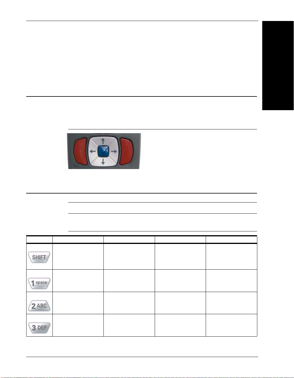
Powering Reader On & Off
To power up the reader, press and hold either of the red trigger buttons for 3
seconds (Figure 1–1). The reader will power down after 2 hours of non-use.
FIGURE 1–1. Trigger Buttons
Keypad/Icon Overview
Note: All characters represented in Table 1–1 are for ASCII mode.
TABLE 1–1. Button Functions
Key Numeric Mode Upper Case Text Mode Lower Case Text Mode Symbol Mode
Toggles between
numeric characters,
upper case text, lower
case text, and symbol
character input
1 Space, 1 Space, 1 Space ) < _
Toggles between
numeric characters,
upper case text, lower
case text, and symbol
character input
Toggles between
numeric characters,
upper case text, lower
case text, and symbol
character input
Toggles between
numeric characters,
upper case text, lower
case text, and symbol
character input
Getting Started
2 A, B, C, 2 a, b, c, 2 ! * = ‘
3 D, E, F, 3 d, e, f, 3 “ + > {
Rev 2.0.0, Jan 2009 HawkEye™ 45T User Manual 1-3
Page 14

Chapter 1 Getting Started
TABLE 1–1. Button Functions (Continued)
Key Numeric Mode Upper Case Text Mode Lower Case Text Mode Symbol Mode
4 G, H, I, 4 g, h, i, 4 # , ? |
5 J, K, L, 5 j, k, l, 5 $ - @ }
6 M, N, O, 6 m, n, o, 6 % . [ ~
7 P, Q, R, S, 7 p, q, r, s, 7 & / \ Space
8 T, U, V, 8 t, u, v, 8 ‘ : ] Space
9 W, X, Y, Z, 9 w, x, y, z, 9 ( ; ^ Space
0 0 0 Toggles between 4 sets
Backspace and clear
messages
Backspace and clear
messages
Backspace and clear
messages
of symbols - when
pressed, the current
symbol set is displayed
Backspace and clear
messages
1-4 HawkEye™ 45T User Manual Rev 2.0.0, Jan 2009
Page 15
Icons
Icons
Table 1–2 through Table 1–7 show the icons, and their definitions, for the HE45T
Display software.
1
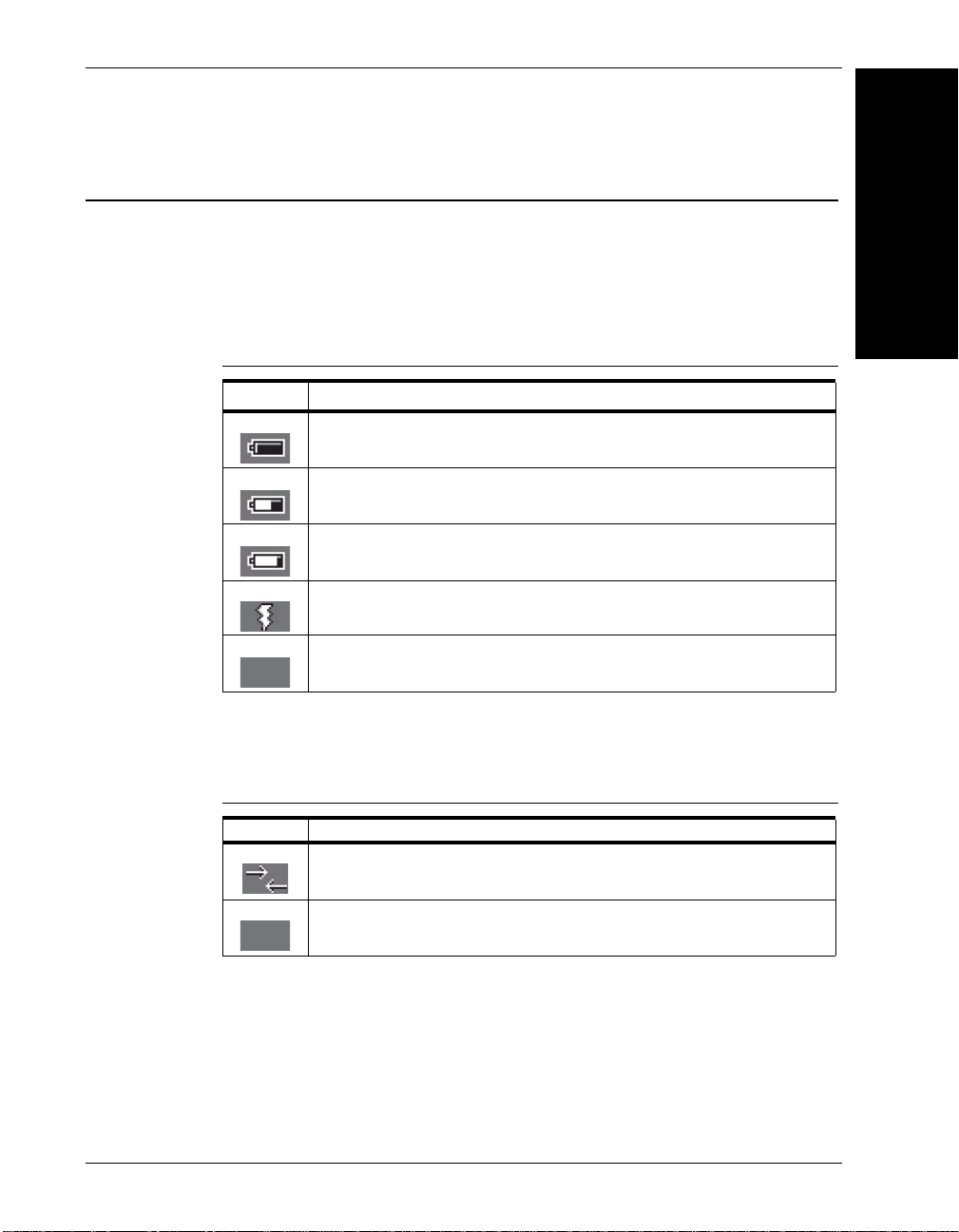
Power Icons
TABLE 1–2. Power Icons
Icon Description
50% to 100% capacity of battery
20% to 50% capacity of battery
0% to 20% capacity of battery – recharge battery as soon as
possible
Battery is recharging
No icon is displayed when battery blank is used with a cabled
reader
Connection Icons
TABLE 1–3. Connection Icons
Icon Description
Reader is connected physically or wirelessly to a receiving device (computer,
handheld, etc.)
Note: Some RS232 configurations can not be detected
No icon is displayed when the reader does not detect a connection
Getting Started
Rev 2.0.0, Jan 2009 HawkEye™ 45T User Manual 1-5
Page 16
Chapter 1 Getting Started
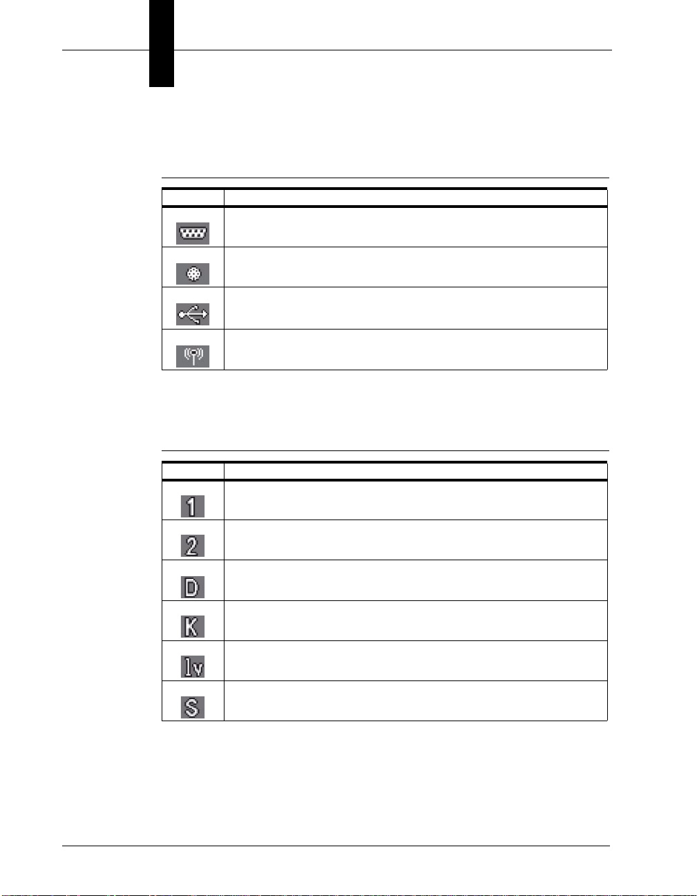
Communication Mode Icons
TABLE 1–4. Communication Mode Icons
Icon Description
RS232 communication mode enabled
PS2 communication mode enabled
USB communication mode enabled
Bluetooth communication mode enabled
Packet Mode Icons
TABLE 1–5. Packet Mode Icons
Icon Description
One way mode – no acknowledgement required
Two way mode – packetized, bidirectional communication between a HE45T and an
application (may also indicate download mode)
Downloader mode
Keyboard mode – can be used as either USB keyboard or PS/2 keyboard input mode
Virtual COM Port One Way mode
Secure mode – data encryption mode enabled
1-6 HawkEye™ 45T User Manual Rev 2.0.0, Jan 2009
Page 17
Memory Icons
TABLE 1–6. Memory Icons
Icon Description
No stored data
Some stored data
Memory is at least 90% full
No batch mode – data will not be stored in the reader’s memory if not connected
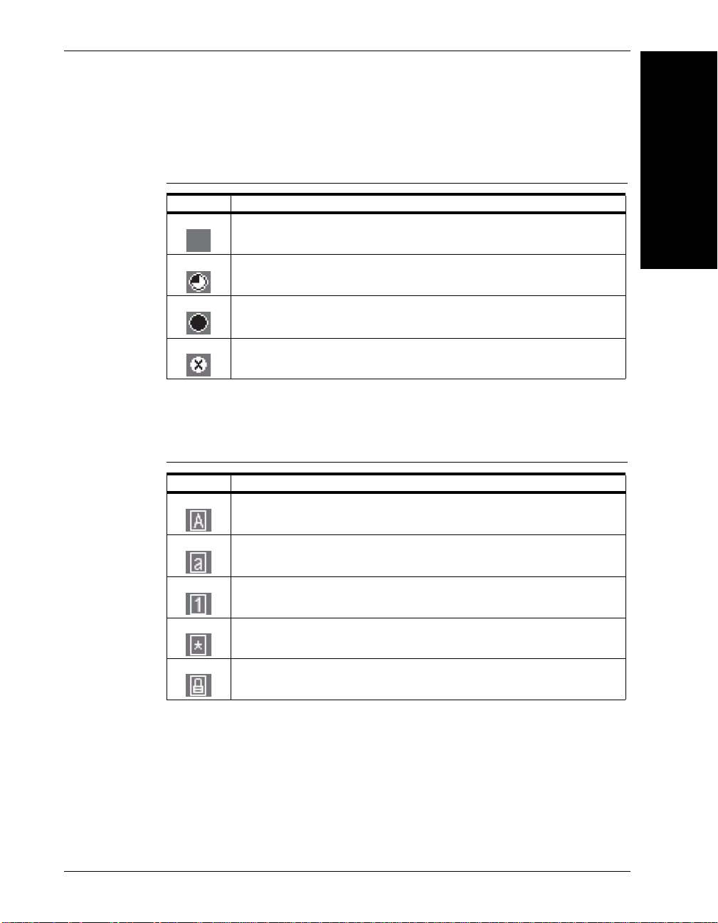
Input Mode Icons
TABLE 1–7. Icons
Icon Description
Caps Lock – data entered manually on the keypad will be in capital letters
Icons
1
Getting Started
Lower Case – data entered manually on the keypad will be in lower case letters
Numeric – data entered manually on the keypad will be numeric
Symbol – data entered manually on the keypad will be symbols
Locked – buttons pushed on the reader’s keypad will be ignored
Rev 2.0.0, Jan 2009 HawkEye™ 45T User Manual 1-7
Page 18

Chapter 1 Getting Started
Flexible Connector
Attaching the H2 Cabled Handle
The HE45T uses the battery compartment to “snap to” the handle. Figure 1–2
shows the H2 handle with flexible connector. Figure 1–3 shows the battery blank.
FIGURE 1–2. H2 Handle with Flexible Connector
FIGURE 1–3. H2 Handle with Battery Blank
1-8 HawkEye™ 45T User Manual Rev 2.0.0, Jan 2009
Page 19

Attaching the H2 Cabled Handle
To attach the handle to the reader:
1. Push the 8-pin DIN connector at the end of the reader into the flexible
connector at the end of the handle, as shown in Figure 1–4.
FIGURE 1–4. Attaching the H2 Handle
1
Getting Started
2. Insert the tab on the back of the handle into the reader (Figure 1–4).
3. Snap the reader onto the handle, matching the battery compartment to the
battery connectors, visible inside the handle, as shown in Figure 1–4.
The HE45T can be secured further with threaded screws on the under side of the
handle, as shown in Figure 1–5.
Rev 2.0.0, Jan 2009 HawkEye™ 45T User Manual 1-9
Page 20
Chapter 1 Getting Started
FIGURE 1–5. Location of Threaded Screws
Attaching the BH1/BH2 Battery Handle
The HE45T uses the battery compartment to “snap to” the handle. The BH1/BH2
handle is shown in Figure 1–6. The handle with battery is shown in Figure 1–7.
FIGURE 1–6. BH1/BH2 Handle
1-10 HawkEye™ 45T User Manual Rev 2.0.0, Jan 2009
Page 21
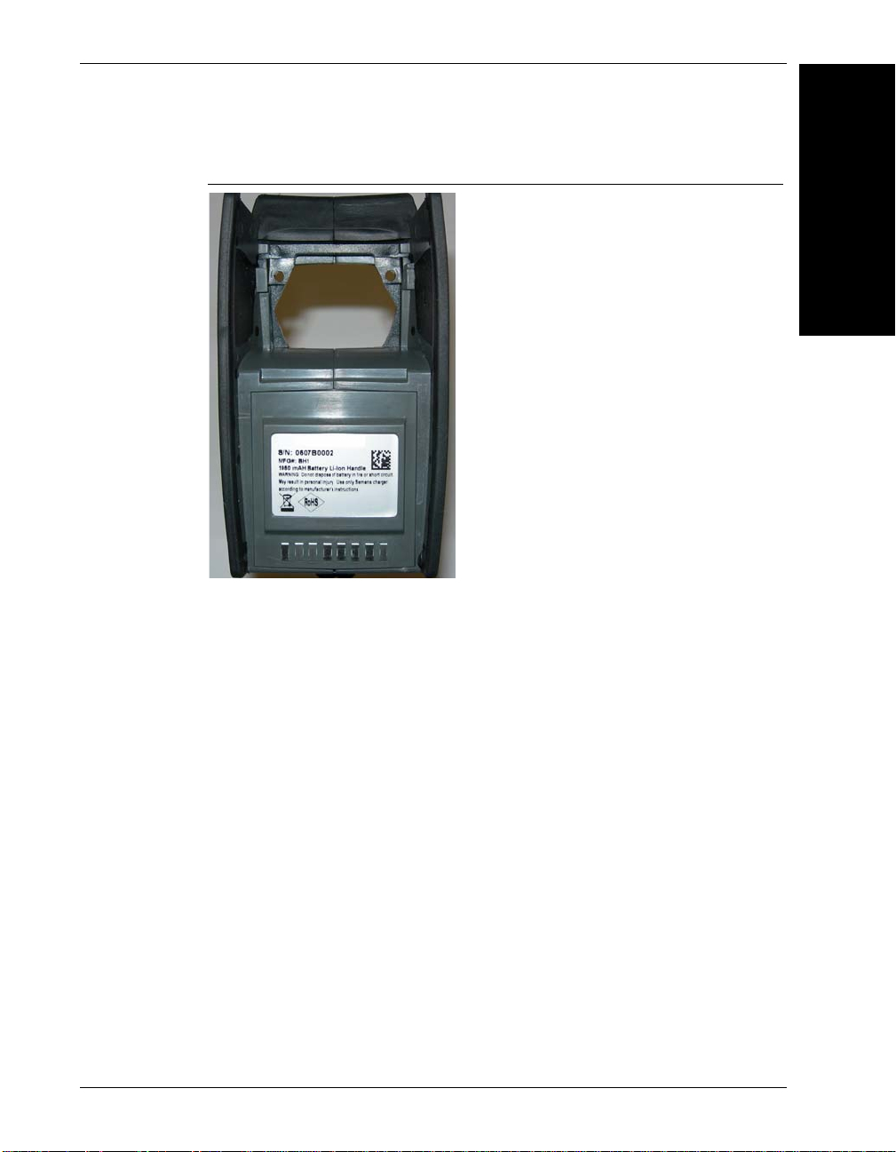
Attaching the BH1/BH2 Battery Handle
FIGURE 1–7. BH1/BH2 Handle with Battery
To attach the handle to the reader:
1
Getting Started
1. Insert the tab on the back of the handle into the reader, as shown in
Figure 1–8.
2. Snap the reader onto the handle, matching the battery compartment to the
battery connectors, visible inside the handle, as shown in Figure 1–8.
Rev 2.0.0, Jan 2009 HawkEye™ 45T User Manual 1-11
Page 22

Chapter 1 Getting Started
FIGURE 1–8. Attaching the BH1/BH2 Handle
The HE45T can be secured further with threaded screws on the under side of the
handle, as shown in Figure 1–9.
FIGURE 1–9. Location of Threaded Screws
1-12 HawkEye™ 45T User Manual Rev 2.0.0, Jan 2009
Page 23

Charging the Lithium Ion Battery
The battery automatically charges every time a cable interface is attached to the
reader and the host is powered up.
Note: The RS-232 interface power adapter must be plugged into a wall socket for
the reader to charge.
If you power up the HE45T with a completely discharged battery, it will take up
to 10 minutes before the reader will become operational.
Batch Operation
Note: To utilize batch functionality, you will need to use the BH1 or BH2 battery
handle.
Batch data storage and data transfer are controlled by the resident JavaScript
application on your HE45T reader. Please consult the HE45T Display User
Manual for the application on your HE45T for instructions on how to control
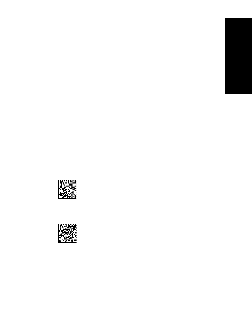
data storage and transfer. For Auto Transfer Buffer Memory, use the codes in
Figure 1–10, too:
Batch Operation
1
Getting Started
Rev 2.0.0, Jan 2009 HawkEye™ 45T User Manual 1-13
Page 24

Chapter 1 Getting Started
Send & Buffer
Mode (Default)
Log Only Mode
Send & Log Mode Tr ansfer All Data in Memory
Enable Auto Transfer
Buffer Memory (Default)
Transfer Only Unsent
Data in Memory
Delete Scanned Data
from Memory
Disable Auto Transfer
Buffer Memory
FIGURE 1–10. Batch Data Storage & Transfer Codes
1-14 HawkEye™ 45T User Manual Rev 2.0.0, Jan 2009
Page 25
RS232 Considerations
RS-232 Batch Cable - Detect (Default)
RS-232 Cabled - No Power
M073_02
M074_02
•In RS-232 Batch Cable - Detect mode, the HE45T will detect if it is
connected to a powered serial cable, and will send the data. If a powered
serial cable is not connected or if the power adapter is not connected to the
serial cable, the HE45T will buffer the data. When the HE45T is then
connected to a powered serial cable, the data will automatically upload.
•In RS-232 Cabled - No Power mode, the HE45T will behave as if it is
always connected even though the serial cable is disconnected or the power
adapter is unplugged. Scanned data will be sent, regardless of connection
status. Data scanned in Cabled mode will be lost if the HE45T is not
connected to the serial cable. It will not buffer the data, unless Send & Store
mode has been enabled.
Note: If you are in RS232 Cabled-No Power mode, when you place a reader in a
charger, the reader will behave as if it is being cabled, and download the data.
THE DATA WILL BE ERASED FROM MEMORY. To disable this feature, scan
the RS232 Cable - Detect code.
Batch Operation
1
Getting Started
FIGURE 1–11. RS-232 Batch Cable - Detect & Cabled - No Power Codes
Rev 2.0.0, Jan 2009 HawkEye™ 45T User Manual 1-15
Page 26

Chapter 1 Getting Started
Cabled Operation
The HE45T is available with USB, RS-232 and PS2 cables. All of the cables are
connected to the HE45T with a 8-pin DIN connector. Different cables may be
required for different hosts.
• HE45T with H2 Cabled Handle — The 8-pin DIN connection is at the
bottom of the handle. Firmly push the 8-pin connector into the bottom of the
handle. The cable has a locking mechanism that will firmly hold the cable in
place (Figure 1–12). To detach the cable from the reader, you must pinch the
plastic on the 8-pin DIN (Figure 1–12) and pull back to disengage the
connector.
FIGURE 1–12. Handle with Cable Attached
Install the optional cable clip to further secure the cable to the handle with
two threaded screws, as shown in Figure 1–13.
1-16 HawkEye™ 45T User Manual Rev 2.0.0, Jan 2009
Page 27

Cabled Operation
FIGURE 1–13. Securing Cable Clip with Two Threaded Screws
• HE45T with BH1/BH2 Battery Handle — Firmly push the 8-pin connector
into the back end of the reader, as shown in Figure 1–14. The cable has a
locking mechanism that will firmly hold the cable in place. To detach the
cable from the reader, you must pinch the plastic on the 8-pin DIN and pull
back to disengage the connector.
FIGURE 1–14. Handle with Cable Attached
1
Getting Started
USB Cable Installation
To connect the HE45T to your host computer via USB interface:
Rev 2.0.0, Jan 2009 HawkEye™ 45T User Manual 1-17
Page 28

Chapter 1 Getting Started
USB Keyboard Mode
Save Settings
1. Make sure the USB cable is sufficiently attached to your HE45T
(Figure 1–12 and Figure 1–14).
FIGURE 1–15. Installing the USB Cable
2. You DO NOT need to power off your host computer (Figure 1–15). The
HE45T with USB interface can be plugged into any host while the computer
is powered up.
3. Connect the USB interface cable to the host (Figure 1–15). If you are unsure
of the proper location to connect the USB cable, please consult the manual of
your host computer.
4. The USB interface does not require an additional power supply. If you are
using a battery handle (BH1 or BH2) for batch mode, the HE45T will
automatically recharge the battery whenever the reader is a attached to a host
that is powered up.
5. The HE45T will power on automatically.
6. Scan the USB Keyboard Mode code and then the Save Settings code to
configure the reader:
FIGURE 1–16. USB Keyboard Mode & Save Settings Codes
7. Your HE45T should be ready for use. Open the application on your host
computer that you wish to send data to and begin scanning.
1-18 HawkEye™ 45T User Manual Rev 2.0.0, Jan 2009
Page 29
Cabled Operation
USB Keyboard USB Downloader
Reset to USB Factory Defaults
Radio settings will not be reset with this code.
USB Communication Settings
• USB Keyboard Mode — Data is sent from the Reader and interpreted by the
host just as if a US keyboard was being used to enter data.
• USB Downloader — This mode is the standard way of transferring
unformatted, unpacketized data through the USB port.
Scan the codes in Figure 1–17 to set the appropriate USB communication setting:
FIGURE 1–17. USB Communication Settings Codes
1
Getting Started
Note: The USB Factory Defaults include all the other settings, such as
symbology, trigger, etc.
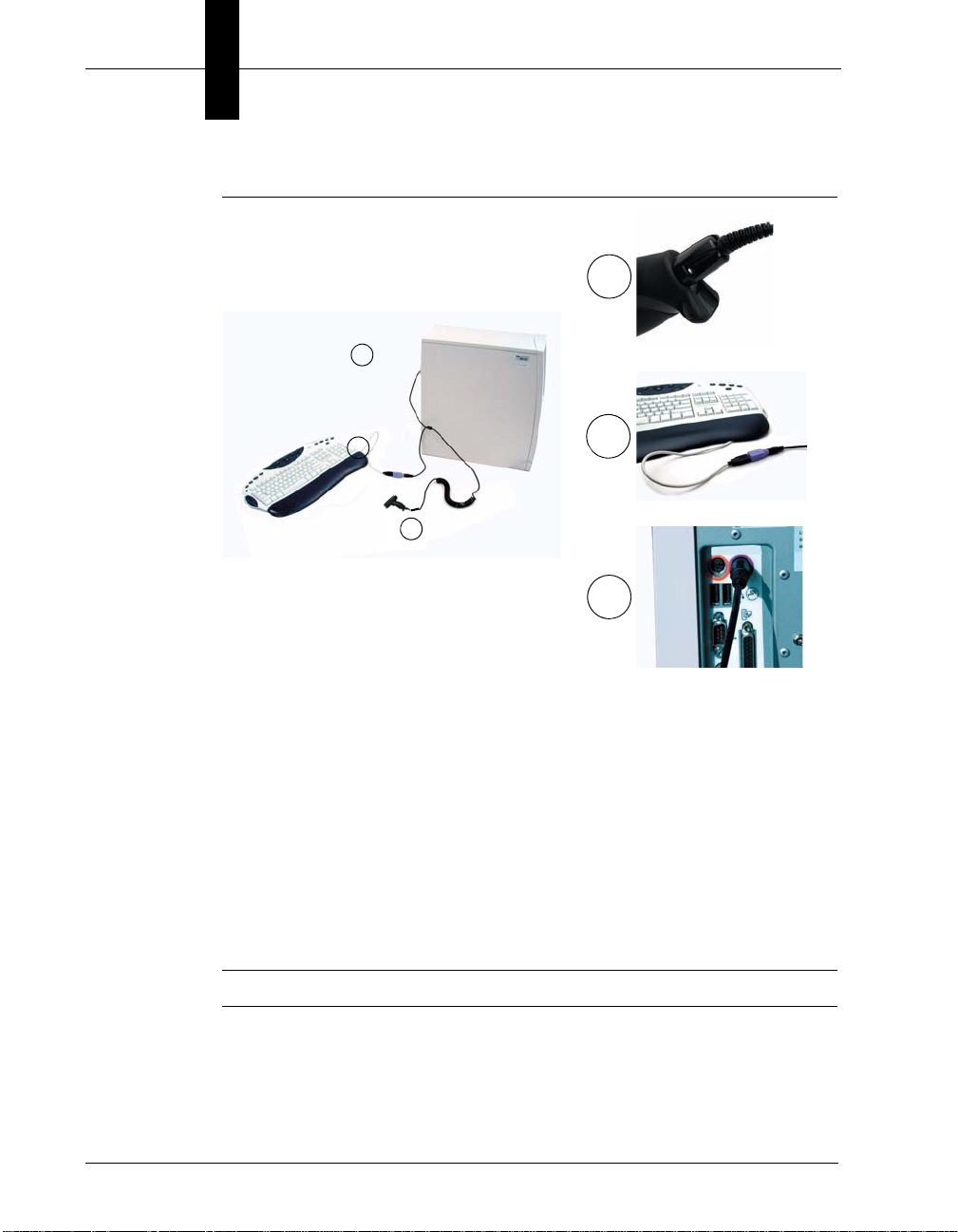
PS2 Cable Installation
1. Power off the host computer.
2. Attach the end of the PS2 cable with the single connector (A) to the HE45T.
3. If an external keyboard exists, detach your keyboard from the host and
connect the appropriate connector to the PS2 cable (B).
4. Connect the other connector to host computer into keyboard port (C). The
Rev 2.0.0, Jan 2009 HawkEye™ 45T User Manual 1-19
HE45T is powered by the PS2 port and does not require a power supply.
Page 30
Chapter 1 Getting Started
A
B
C
B
C
A
Notice
Microscan does not recommend using Batch or Bluetooth Radio modes with
the PS2 interface. You may need to disconnect the HE45T and the keyboard
which may result in the host computer freezing.
FIGURE 1–18. Installing the PS2 Cable
5. Set the HE45T to PS2 mode by scanning the PS2 Mode code in Figure 1–19.
6. Scan the Save Settings code.
7. Your HE45T is now ready. Open the appropriate application and begin
scanning data.
Note: Microscan does not guarantee compatibility with all models of laptops.
1-20 HawkEye™ 45T User Manual Rev 2.0.0, Jan 2009
Page 31

PS2 Communication Settings
PS2 Mode
Save Settings
Reset to PS2 Factory Defaults
Scan the codes in Figure 1–19 to set the reader to the PS2 communication setting:
FIGURE 1–19. PS2 Communication Settings Codes
Note: The PS2 Factory Defaults include all the other settings, such as symbology,
trigger, etc.
RS-232 Cable Installation
To connect the HE45T to your host computer via RS-232 interface:
1. Make sure the RS-232 cable is sufficiently attached to your reader
(Figure 1–12 and Figure 1–14).
Cabled Operation
1
Getting Started
2. Connect the RS-232 interface cable to your host computer (Figure 1–20). If
you are unsure of the proper location to connect the RS-232 cable, please
consult the manual of your host computer.
3. The RS-232 interface should have come with a power supply. Plug the
power supply adapter into the RS-232 interface cable (Figure 1–20), and
then plug the power adapter into a wall socket (Figure 1–20). The RS-232
interface does not require additional power. However, if you are using the
RS-232 interface and utilizing Batch functionality with the BH1/BH2
battery handle, the HE45T will recharge the battery whenever the reader is
attached to a RS-232 cable that is plugged into a wall socket.
Rev 2.0.0, Jan 2009 HawkEye™ 45T User Manual 1-21
Page 32

Chapter 1 Getting Started
RS-232 One Way Mode
Save Settings
Caution
You must use a Microscan-approved power adapter. Reader failure due to use
of incorrect power adapter will void all warranties.
7 Data Bits 8 Data Bits (Default)
FIGURE 1–20. Installing the RS-232 Cable
4. The HE45T will power on automatically.
5. Scan the RS-232 One Way Mode code and then the Save Settings code to
configure the reader:
FIGURE 1–21. RS-232 One Way Mode & Save Settings Codes
6. Your HE45T should be ready for use. Open the application on your host
computer that will receive scanned data and begin scanning.
RS-232 Communication — Data Bit Settings
Scan the codes in Figure 1–22 to set the appropriate data bit:
FIGURE 1–22. RS-232 Data Bit Codes
1-22 HawkEye™ 45T User Manual Rev 2.0.0, Jan 2009
Page 33

RS-232 Communication — Stop Bit Settings
2 Stop Bits1 Stop Bit (Default)
1200 2400 4800 9600
19200 38400
57600 (Default) 115200
Even Odd None (Default)
Scan the codes in Figure 1–23 to set the appropriate stop bit data:
FIGURE 1–23. RS-232 Stop Bit Codes
RS-232 Communication — Baud Rate Settings
Scan the codes in Figure 1–24 to set the appropriate baud rate:
FIGURE 1–24. RS-232 Baud Rate Codes
Cabled Operation
1
Getting Started
RS-232 Communication — Parity Settings
Scan the codes in Figure 1–25 to set parity:
FIGURE 1–25. RS-232 Parity Codes
Rev 2.0.0, Jan 2009 HawkEye™ 45T User Manual 1-23
Page 34

Chapter 1 Getting Started
Cabled - 2 Hours Cabled - Always (Default)
Cabled Reader — Timeout Settings
Scan the codes in Figure 1–26 to set the amount of time a cabled HE45T will be
enumerated before entering sleep mode. The battery is re-charged at the fastest
rate when the HE45T is in sleep mode:
FIGURE 1–26. Cabled Reader Timeout Settings Codes
Bluetooth Radio Operation
Wireless HE45T readers feature a Bluetooth® wireless radio. The radio allows
for point to point wireless communication with other Bluetooth devices that
support serial port protocol (SPP). The following information will give you
general instructions on connecting your HE45T to a desktop or laptop computer
with a Bluetooth radio.
Connecting With A QuickConnect Code
If you purchased a CodeXML Bluetooth Modem or a Belkin® Bluetooth adapter
from Microscan or from an authorized distributor, a QuickConnect code was
included (Figure 1–27).
FIGURE 1–27. QuickConnect Code
The QuickConnect code has the information of the Bluetooth address (often a
reference to go to the BD_ADDR) of that device. You can usually find the
12-character Bluetooth address somewhere on the device near the device’s serial
number (Figure 1–27). This code will link your HE45T directly to the desired
Bluetooth device.
1-24 HawkEye™ 45T User Manual Rev 2.0.0, Jan 2009
Page 35

Bluetooth Radio Operation
Reset to RF
Factory Defaults
Save SettingsQuick Connect
Note: While installing the Bluetooth Configuration Manager software that was
included with your Bluetooth adapter, make sure to note the Virtual COM Port
number the software assigned for the adapter (e.g. COM 10). This is the COM
Port your HE45T will connect through.
1
To connect your reader, scan the Reset to Factory Defaults in Figure 1–28. Then,
the QuickConnect Code and your HE45T will automatically connect. You should
also scan the Save Settings code if you want to save these settings.
Note: If the HE45T powers off without scanning the Save Settings code, you will
lose your settings.
FIGURE 1–28. Reset to RF Factory Defaults Code
Radio Range and Transferring Data
The HE45T radio is a Class 1 device. If connected to another Class 1 device, the
reader has roughly a 300 foot line of sight operating range. If connecting to a
Class 2 or Class 3 device, the operating range may drop to match the lower range.
Once a reader is connected, the application software on the host must be open to
receive data.
Getting Started
When the HE45T detects the radio is out of range, the HE45T will store data on
the reader’s non-volatile memory. The reader will continue to try and send data
until radio is back in range. Once the data is sent, the data will be erased from the
reader’s memory. If the radio cannot connect in 90 seconds, it will give an error
beep. The reader will continue to try and connect until it has reached the
programmable radio timeout setting.
Rev 2.0.0, Jan 2009 HawkEye™ 45T User Manual 1-25
Page 36

Chapter 1 Getting Started
RF One Way Mode
(Max Range)
RF One Way Mode
(Max Reliability)
RF Two Way Mode
The HE45T Bluetooth protocol allows for two forms of communication:
• One Way Mode — Defined as one way communication between the reader
and host. One Way mode is only recommended when connecting to a device
well within its specified range, or if connected to a device without an
operating system (i.e., printer). There are two settings in this mode:
– Max Range (Default) — Greater range but data reliability is lower
– Max Reliability — Limits range but reliability is improved
FIGURE 1–29. RF One Way Mode Range & Reliability Codes
Note: While robust, One Way Mode doesn’t guarantee data integrity and you
may have data loss when operating in the fringes of radio range or in the presence
of radio interference.
• RF Two Way Mode — This is two way communication between the host
and reader. This requires the implementation of software at the application
level. The reader receives confirmation via packet protocol verification and
is 100% reliable. Data will be retransmitted automatically if necessary.
FIGURE 1–30. RF Two Way Mode Codes
Note: You will need to install application software that supports packet
communication to operate in RF Two Way Mode. Microscan offers the
CodeXML Bluetooth Modem and a Windows or Pocket PC version of software
called CodeXML Router - Bluetooth Edition (BE) that provides for end-to-end
1-26 HawkEye™ 45T User Manual Rev 2.0.0, Jan 2009
Page 37

Bluetooth handshakes that eliminate out-of-range data loss. CodeXML Router -
Save Settings
Bluetooth Disconnect
BE also offers Bluetooth to keyboard wedge communication for applications that
require keyboard port input.
If you are using the CodeXML Bluetooth modem, you must use RF Two Way
Mode.
Save Settings
Scan the code in Figure 1–31 to make the RF settings permanent on the reader:
FIGURE 1–31. Save Settings
Disconnecting from the Reader
You can force a disconnect by reading the disconnect code in Figure 1–32 (the
HE45T may not appear disconnected in the slave Bluetooth connection manager
for 10 – 15 seconds after the command is issued). The HE45T will also
disconnect after 90 seconds of inactivity.
Bluetooth Radio Operation
1
Getting Started
Note: You may change the radio frequency sleep timeout setting; however, it may
reduce battery life.
FIGURE 1–32. Bluetooth Disconnect Code
Reconnecting to the Reader
If the device is saved in RF mode, it will automatically reconnect when the
HE45T:
• Is powered up
Rev 2.0.0, Jan 2009 HawkEye™ 45T User Manual 1-27
Page 38

Chapter 1 Getting Started
Bluetooth Radio Auto
Connect On (Default)
Bluetooth Radio Auto
Connect Off
Bluetooth Radio
Auto Disconnect On
Bluetooth Radio
Auto Disconnect Off (Default)
• Wakes from sleep mode
• Reads another code
Bluetooth Radio — Auto Connect & Auto Disconnect
After coming out of sleep mode or after powering up (you need to save the
connection), the HE45T tries to auto connect with the last Bluetooth radio it was
connected with. You may always connect by scanning a QuickConnect code.
Scan the codes in Figure 1–33 to enable/disable the Auto Connect feature for the
Bluetooth radio:
FIGURE 1–33. Bluetooth Radio Auto Connect & Disconnect Codes
The Auto Disconnect feature is used when multiple HE45T readers are
connecting to the same Bluetooth Radio. By enabling Auto Disconnect, the
HE45T radio disconnects after each data transmission, allowing other radios to
connect.
Scan the codes in Figure 1–34 to enable/disable the Auto Disconnect feature for
the Bluetooth radio:
FIGURE 1–34. Bluetooth Radio Auto Disconnect On/Off Codes
Note: Auto Connect should always be set to “On” if Auto Disconnect is set to
“On”. (Otherwise the QuickConnect code would need to be re-scanned after
every disconnect).
1-28 HawkEye™ 45T User Manual Rev 2.0.0, Jan 2009
Page 39

Bluetooth Radio Operation
90 Seconds
(Default)
5 Minutes 10 Minutes
15 Minutes 30 Minutes 1 Hour 2 Hours
Bluetooth Radio — Timeout Settings (Uncabled)
Scan the codes in Figure 1–35 to set the period of time before the Bluetooth
Radio will go into sleep mode from inactivity:
Note: Increasing the time before the reader will timeout will decrease battery life.
If the reader has power (USB cable, power cable, etc.), it will disconnect based
on cable timeout settings.
FIGURE 1–35. Bluetooth Radio Timeout Settings Codes
1
Getting Started
Rev 2.0.0, Jan 2009 HawkEye™ 45T User Manual 1-29
Page 40

Chapter 1 Getting Started
Bluetooth - Out of Range Beep: On
Bluetooth - Out of Range Notify with Vibrate: On
Bluetooth - Out of Range Vibrate & Beep: On
Bluetooth - Out of Range Vibrate and/or Beep: Off (Default)
Bluetooth Radio — Out of Range Notification Settings
Scan the codes in Figure 1–36 to enable a beep or vibrate notification when the
radio goes out of range:
FIGURE 1–36. Bluetooth Radio Out of Range Notification Codes
1-30 HawkEye™ 45T User Manual Rev 2.0.0, Jan 2009
Page 41

Reader Feedback
Reader Feedback
Table 1–8 through Table 1–11 show potential icon combinations in the HE45T
Display software. Consult the table to verify a configuration.
TABLE 1–8. Possible HE45T Configurations (RS-232)
Mode Description
RS-232 One Way This is the standard way of transferring unformatted, unpacketized data
through the serial/RS232 port.
RS-232 Two Way This mode allows for reliable communication by utilizing packet
acknowledgement protocol.
RS-232 Secure This mode is used for transferring data in an encrypted format from the
HE45T to a host computer through the serial/RS232 port.
1
Getting Started
TABLE 1–9. Possible HE45T Configurations (PS2)
Mode Description
PS2 Keyboard This is the standard mode for tra nsferring data from the HE45T through a
PS2 port.
Rev 2.0.0, Jan 2009 HawkEye™ 45T User Manual 1-31
Page 42

Chapter 1 Getting Started
TABLE 1–10. Possible HE 45T Co nfigurations (USB)
Mode Description
USB One Way This is the standard way of transferring unformatted, unpacke tized
data through a USB port.
USB Two Way This mode is used when there is a need for packetized, bidirectional
communication between the HE45T and an application through a
USB port.
This mode emulates the transfer of data from the HE45T to a host
computer via a keyboard interface.
USB Virtual COM Port 1 This mode allows communication between a USB port and an
application expecting serial input. A virtual com driver must be loaded
onto the host computer before reader can be utilized in this mode.
USB Secure This mode is used for transferring data in an encrypted format from
the HE45T to a host computer through a USB port.
USB Downloader This mode is used when downloading firmware changes to the
reader.
1-32 HawkEye™ 45T User Manual Rev 2.0.0, Jan 2009
Page 43

Targeting and Reading Techniques
TABLE 1–11. Possible HE 45T Co nfigurations (Bluetooth Radio)
Mode Description
Bluetooth One Way This is a way of transferring unformatted, unpacketized data by radio
frequency (Bluetooth).
Bluetooth Two Way This mode is used when there is a need for packetized, bidirectional
communication between the HE45T and an application by radio
frequency (Bluetooth). This requires implementation of software at the
application level. The reader receives confirmation via packet protocol
verification and is 100% reliable. Microscan offers a Windows or
PocketPC version of software called CodeXML Router Bluetooth Edition
(BE) that automatically provides packet protocol verification. CodeXML
Router BE allows for end-to-end Bluetooth handshakes that eliminate
issues with out-of-range data loss.
Bluetooth Secure This mode is used for transferring data in an encrypted format from the
HE45T to a host computer through a Bluetooth connection.
1
Getting Started
Targeting and Reading Techniques
The HE45T utilizes digital camera technology to take a picture of a symbol.
Once an image is captured, the HE45T utilizes advanced decoding algorithms to
extract data from the captured image.
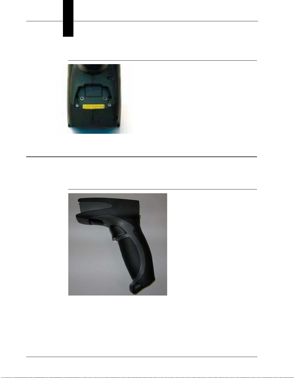
The reader features left and right triggers. These triggers may be programmed to
perform various features. The reader is shipped with the left trigger and right
trigger functioning as a decode symbol command.
The H2 Cabled Handle and BH1/BH2 Battery Handle each feature a trigger on
the handle. The two triggers on the top of the reader also work when the handle is
attached.
Rev 2.0.0, Jan 2009 HawkEye™ 45T User Manual 1-33
Page 44

Chapter 1 Getting Started
FIGURE 1–37. Handle with Trigger
Note: The trigger on the handle attachment is light. Squeezing too hard may
damage the reader.
1-34 HawkEye™ 45T User Manual Rev 2.0.0, Jan 2009
Page 45

Targeting and Reading Techniques
To read a symbol with the HE45T:
1. The HE45T features omnidirectional decoding. Center the symbol in any
orientation within the laser dot aiming pattern (Figure 1–38).
FIGURE 1–38. Centering the Symbol Within the Laser Dot
Note: The HE45T can read a symbol that is not centered; however, the
HE45T performs best when a code is centered.
The HE45T features omnidirectional decoding. Aiming the targeting laser at
the center of the symbol ensures the best performance for decoding. The
HE45T can read a symbol that is not centered and, under certain
circumstances if multiple symbols are within the field of view, the user must
take care of which symbol is read. The decoder will start from the center, but
if the center symbol is not decodable, it may decode another symbol, if
multiple symbols are present within the field of view.
1
Getting Started
2. The HE45T was developed to decode both very small 2-D symbols and
larger 1-D symbols. The reader has an innovative dual field decode zone.
The HE45T DECODES BOTH ZONES SIMULTANEOUSLY. The reader
has a lens focused on a near-field for smaller codes (optimal focal point is 4
inches) and one lens focused on a far-field for larger codes (optimal focal
point 9 inches). To read smaller symbols move the HE45T closer to the
symbol. To read larger symbols move the reader farther away from the
symbol. The entire HE45T decode zone varies between two (2”) and twenty
(20+”) or more inches.
3. Hold the HE45T still - DO NOT SWIPE OR MOVE THE READER. Press
the trigger until the HE45T beeps, indicating the code has been successfully
decoded.
4. To read a symbol with a shiny background, hold the HE45T slightly tilted to
avoid the reflected light from the LEDs.
Rev 2.0.0, Jan 2009 HawkEye™ 45T User Manual 1-35
Page 46

Chapter 1 Getting Started
5. The reader may be optimized to your specific environment by scanning
codes in Chapter 6, “Advanced Decoder Performance”.
1-36 HawkEye™ 45T User Manual Rev 2.0.0, Jan 2009
Page 47

Imager Field of View and Resolution
1024
640
640
Far
Near
Imager Field of View and Resolution
The HE45T’s megapixel imager, with a dual field optical system, can provide
you the best image for 1-D and 2-D applications.
The 1.3 Million Pixel imager is divided into near field and far field decode zones.
In each zone, the resolution is 1024 x 640 pixels (see Figure 1.25). In this mode
of operation the reader utilizes the highest resolution creating the widest working
range on bar code and 2-dimensional symbols of all densities. The trade-off is the
amount of time the reader spends processing the image. This time can be reduced
by optimization functions:
• If only the near field is used (small, high density symbols), the far field
image can be ignored.
• If only the far field is used (large, lower density symbols), the near field can
be ignored.
Further optimization may be obtained by “windowing” the field to a smaller area.
FIGURE 1–39. SXGA Imaging Area
1
Getting Started
Rev 2.0.0, Jan 2009 HawkEye™ 45T User Manual 1-37
Page 48

Chapter 1 Getting Started
FIGURE 1–40. HE45T Focal Lengths
1-38 HawkEye™ 45T User Manual Rev 2.0.0, Jan 2009
Page 49

2
CHAPTER 2 Optimization and Trigger
Programming
Introduction
The HE45T comes with SXGA mode and its dual field optical system activated
for all the triggers. From the moment you turn on your HE45T, you are taking full
advantage of the dual path 1.3 megapixel imager and the
400 MHz processor with Microscan’ industry leading DPM technology.
2
Optimization and
Trigger Programming
The HE45T is easily customizable; each trigger can be independently
programmed for different behavior.
• Near Field (NF) — The nearest field of the HE45T’s two image fields. It has
an optimal focal point of 4” (101.6 mm) away from the lens of the reader.
The width of the Field of View is 1.5” (38.1 mm) at the optimal focus point.
• Far Field (FF) — The farthest field of the HE45T’s two image fields. It has
an optimal focal point of 9” (228.6 mm) away from the lens of the reader.
The width of the Field of View is 4” (101.6 mm) at the optimal focus point.
The following sections provide you with the ability to program individual
triggers, or all triggers, to perform with different parameters.
Rev 2.0.0, Jan 2009 HawkEye™ 45T User Manual 2-1
Page 50

Chapter 2 Optimization and Trigger Programming
Read Codes with Both Imagers (Default)
Read with Far-Field Imager ONLY
Read with Near-Field Imager ONLY
Read Codes with Both Imagers (Default)
Read Code with Far-Field Imager Only
Read Code with Near-Field Imager ONLY
Left Trigger Programming
Scan the codes in Figure 2–1 to set the left trigger functionality:
FIGURE 2–1. Left Trigger Programming Codes
Right Trigger Programming
Scan the codes in Figure 2–2 to set the right trigger functionality:
FIGURE 2–2. Right Trigger Programming Codes
2-2 HawkEye™ 45T User Manual Rev 2.0.0, Jan 2009
Page 51

Handle Trigger Programming
Read Codes with Both Imagers (Default)
Read Code with Far-Field Imager ONLY
Read Code with Near-Field Imager ONLY
Both Near & Far Field On
Near Field Only On
Far Field Only On
Off (Default)
Scan the codes in Figure 2–3 to set the handle trigger functionality:
FIGURE 2–3. Handle Trigger Programming Codes
Continuous Scan Settings
Handle Trigger Programming
2
Optimization and
Trigger Programming
Scan the codes in Figure 2–4 to turn continuous scanning on/off:
FIGURE 2–4. Continuous Scan On/Off Codes
Note: This function is only recommended for short term use because of battery
consumption (see “Continuous Scan — Sleep Timeout” on page 2-4).
Rev 2.0.0, Jan 2009 HawkEye™ 45T User Manual 2-3
Page 52

Chapter 2 Optimization and Trigger Programming
Cabled - 2 Hours
Cabled - Always (Default)
Uncabled - 5 Minutes (Default)
Uncabled - 15 Minutes
Uncabled - 30 Minutes
Continuous Scan — Sleep Timeout
Scan the codes in Figure 2–5 to set the amount of time a cabled HE45T will
operate in continuous scan mode
FIGURE 2–5. Continuous Scan Sleep Timeout Codes
Scan the codes in Figure 2–6 to set the amount of time an uncabled HE45T will
operate in continuous scan
FIGURE 2–6. Continuous Scan Wait Before Enter Sleep Mode Codes
before entering sleep mode:
mode before entering sleep mode:
Note: This function is only recommended for short term use because of battery
consumption.
2-4 HawkEye™ 45T User Manual Rev 2.0.0, Jan 2009
Page 53

Motion Detection Scan Settings
0 Seconds (Default) 1 Second 3 Seconds
0 Seconds (Default) 1 Second 3 Seconds
On
Off (Default)
Continuous Scan — Trigger Delays
Scan the codes in Figure 2–7 to set delay time between scans:
FIGURE 2–7. Continuous Scan Trigger Delay Codes
Continuous Scan — Duplicate Scan Delay
Scan the codes in Figure 2–8 to set the delay time for reading duplicate codes:
FIGURE 2–8. Continuous Scan Duplicate Scan Codes
2
Optimization and
Trigger Programming
Motion Detection Scan Settings
Scan the codes in Figure 2–9 to set the reader to read when it detects motion in its
scanning zone:
FIGURE 2–9. Motion Detection Scan On/Off Codes
Rev 2.0.0, Jan 2009 HawkEye™ 45T User Manual 2-5
Page 54

Chapter 2 Optimization and Trigger Programming
2-6 HawkEye™ 45T User Manual Rev 2.0.0, Jan 2009
Page 55

3
CHAPTER 3 HE45T Programming:
Symbology Settings
Use the programming codes in this chapter to change the symbology settings on
the HawkEye™ 45T.
To reset the reader to factory defaults or to save the current settings, scan one of
the codes in Figure 3–1.
3
Symbology Settings
HE45T Programming:
Rev 2.0.0, Jan 2009 HawkEye™ 45T User Manual 3-1
Page 56

Chapter 3 HE45T Programming: Symbology Settings
Save Settings
Reset to USB Factory Defaults
Radio setting will not be reset with this code
Reset to PS2 Factory Defaults
Radio setting will not be reset with this code
Reset to RS-232 Factory Defaults
Radio setting will not be reset with this code
Reset to RF One Way Factory Defaults
Clear All CodeXML Rules
FIGURE 3–1. Reset to Factory Defaults Codes
Readers are shipped from manufacturing with default communication settings
that are hardware dependent.
Note: If you do not save your settings and the HE45T loses power, you will lose
your settings.
3-2 HawkEye™ 45T User Manual Rev 2.0.0, Jan 2009
Page 57

Codabar Symbology
Codabar On
(Default)
Codabar Off
Sample Codabar
Code 39 On Code 39 Off (Default)
Sample Code 39 Code
Scan the codes in Figure 3–2 to enable/disable Codabar symbology settings:
FIGURE 3–2. Codabar Symbology Codes
Code 39 Symbology
Scan the codes in Figure 3–3 to enable/disable Code 39 symbology settings:
Codabar Symbology
3
Symbology Settings
HE45T Programming:
FIGURE 3–3. Coded 39 Symbology Codes
Rev 2.0.0, Jan 2009 HawkEye™ 45T User Manual 3-3
Page 58

Chapter 3 HE45T Programming: Symbology Settings
Code 93 On
Code 93 Off (Default)
Sample Code 93 Code
Code 128 On
Code 128 Off (Default)
Sample Code 128 Code
Code 93 Symbology
Scan the codes in Figure 3–4 to enable/disable Code 93 symbology settings:
FIGURE 3–4. Code 93 Symbology Codes
Code 128 Symbology
Scan the codes in Figure 3–5 to enable/disable Code 128 symbology settings:
FIGURE 3–5. Code 128 Symbology Codes
3-4 HawkEye™ 45T User Manual Rev 2.0.0, Jan 2009
Page 59

Interleaved 2 of 5 Symbology
Int 2 of 5 On Int 2 of 5 Off (Default)
Sample Int 2 of 5 Code
PDF 417 On
PDF 417 Off (Default)
Sample PDF 417 Code
Scan the codes in Figure 3–6 to enable/disable Interleaved 2 of 5 symbology
settings:
FIGURE 3–6. Interleaved 2 of 5 Symbology Codes
Interleaved 2 of 5 Symbology
3
PDF 417 Symbology
Scan the codes in Figure 3–7 to enable/disable PDF 417 symbology settings:
FIGURE 3–7. PDF417 Symbology Codes
Symbology Settings
HE45T Programming:
Rev 2.0.0, Jan 2009 HawkEye™ 45T User Manual 3-5
Page 60

Chapter 3 HE45T Programming: Symbology Settings
QR/Micro QR On
QR/Micro QR Off (Default)
Sample QR Code
QR Code Symbology
Scan the codes in Figure 3–8 to enable/disable QR/Micro QR Code symbology
settings:
FIGURE 3–8. QR Code Symbology Codes
3-6 HawkEye™ 45T User Manual Rev 2.0.0, Jan 2009
Page 61

UPC/EAN/JAN
UPC On UPC Off (Default)
UPC Extension On UPC Extension Off (Default)
Sample UPC A Code
All 1D Codes On All 1D Codes Off
Scan the codes in Figure 3–9 to enable/disable UPC/EAN/JAN symbology
settings:
FIGURE 3–9. UPC/EAN/JAN Symbology Codes
UPC/EAN/JAN
3
Symbology Settings
HE45T Programming:
All 1D Bar Codes
Scan the codes in Figure 3–10 to enable all supported 1D bar codes (Code 128,
Code 39, Code 93, I 2 of 5, Codabar, UPC).
Rev 2.0.0, Jan 2009 HawkEye™ 45T User Manual 3-7
FIGURE 3–10. All 1D Codes On/Off
Page 62

Chapter 3 HE45T Programming: Symbology Settings
3-8 HawkEye™ 45T User Manual Rev 2.0.0, Jan 2009
Page 63

4
CHAPTER 4 Department of Defense
Unique Identification (UID)
UID is a mandatory Department of Defense requirement on all solicitations
issued January 1, 2004. This policy mandates the use of Data Matrix symbology
on a large class of equipment and parts procured by DoD. The HE45T reader
complies with Department of Defense Standard Practice Identification
(MIL-STD-130).
4
Once the HE45T decodes the Data Matrix symbol, and, if the Unique Item
Identifier (UII), Current Part Number (CPN), and Lot/Batch Number (LBN) are
turned on, it checks the ISO 15434 syntax with ISO 15418 (ANSI MH10.8.2 - AI
& DI) and ISO 21849 (ATA - TEI) semantics to construct UII, CPN, and LBN.
DoD UID Settings
The following UID data output options are applicable to Data Matrix only and
have no effect on other symbologies:
• UII/CPN DM On — The HE45T is configured to construct Unique Item
Identifier (UII), Current Part Number (CPN), and Lot/Batch Number (LBN).
If there is a valid UII/CPN/LBN, a UII/CPN/LBN string is outputted. For
decoded Data Matrix with invalid UII/CPN/LBN, HE45T stops image
acquisition without an output string. The UII/CPN DM On option will have
the following output format:
Rev 2.0.0, Jan 2009 HawkEye™ 45T User Manual 4-1
Department of
Defense Unique
Page 64

Chapter 4 Department of Defense Unique Identification (UID)
TABLE 4–1. UII/CPN DM On Options
Content of Decoded
Data Matrix UII/CPN
Valid UII UII:UII_data
Example: UII:12345678
Valid CPN
Valid LBN
Valid UII and CPN
Valid UII and LBN
Valid UII and invalid CPN
Valid UII and invalid LBN
Invalid UII and valid CPN
Invalid UII and valid LBN
None of the above
(Invalid UII;
Invalid CPN;
Invalid LBN;
Invalid UII and Invalid CPN;
Invalid UII and Invalid LBN)
CPN:CPN_data
Example: CPN:87654321
LBN:LBN_data
Example: LBN:87654321
UII:UII_data CPN:CPN_data
Example: UII:12345678 CPN:87654321
UII:UII_data LBN:LBN_data
Example: UII:12345678 LBN:87654321
UII:UII_data (CPN ERROR)
Example: UII:12345678 (CPN ERROR)
UII:UII_data (LBN ERROR)
Example: UII:12345678 (LBN ERROR)
(UII ERROR) CPN:CPN_data
Example: (UII ERROR) CPN:87654321
(UII ERROR) LBN:LBN_data
Example: (UII ERROR) LBN:87654321
No output data
• UII/CPN DM with Data Fields — The HE45T is configured to construct
UII/CPN/LBN with all the data fields. The UII/CPN with Data Field option
has the following output format:
UII/CPN; DF0; DF1; DF2; DF3; DF4; DF5; DF6; DF7
4-2 HawkEye™ 45T User Manual Rev 2.0.0, Jan 2009
Page 65

TABLE 4–2. UII/CPN DM with Da ta Field On
Content of Decoded
Data Matrix UII/CPN DF0
Valid UII UII:UII_data
Example: UII:12345678
Valid CPN
Valid LBN
Valid UII and CPN
Valid UII and LBN
Valid UII and Invalid CPN
Valid UII and Invalid LBN
Invalid UII and Valid CPN
Invalid UII and Valid LBN
Invalid UII (UII ERROR: xxxx)
Invalid CPN
Invalid LBN
Invalid UII and Invalid CPN
Invalid UII and Invalid LBN
CPN:CPN_data
Example: CPN:87654321
LBN:LBN_data
Example: LBN:87654321
UII:UII_data CPN:CPN_data
Example: UII:12345678 CPN:87654321
UII:UII_data LBN:LBN_data
Example: UII:12345678 LBN:87654321
UII:UII_data (30P ERROR: xxxx)
UII:UII_data (PNR ERROR: xxxx)
UII:UII_data (240 ERROR: xxxx)
UII:UII_data (30T ERROR: xxxx)
(UII ERROR: xxxx) CPN:CPN_data
(UII ERROR: xxxx) LBN:LBN_data
(15434 ERROR: xxxx)
Example: (UII ERROR: DATA ELEMENT
CHARACTER)
(30P ERROR:xxxx)
(PNR ERROR:xxxx)
(240 ERROR:xxxx)
(30T ERROR:xxxx)
(15434 ERROR: xxxx)
(UII ERROR: xxxx) (30P ERROR: xxxx)
(UII ERROR: xxxx) (PNR ERROR: xxxx)
(UII ERROR: xxxx) (240 ERROR: xxxx)
(UII ERROR: xxxx) (30T ERROR: xxxx)
Constructed UII type
Example: Contruct_1
Constructed CPN type
Example: PNR
Constructed LBN type
Example: 30T
Constructed UII/CPN type
Example: Construct_1/PNR
Constructed UII/LBN type
Example: Construct_1/30T
Constructed UII type
Example: Construct_1
Constructed CPN type:
30P, PNR, 240
Constructed LBN type:
30T
Original decoded data
Original decoded data
Original decoded data
DoD UID Settings
4
Department of
Defense Unique
Rev 2.0.0, Jan 2009 HawkEye™ 45T User Manual 4-3
Page 66

Chapter 4 Department of Defense Unique Identification (UID)
UII/CPN DM On
UII/CPN Off
UII/CPN DM with Data Field
UII/CPN On for All Symbologies
The following options apply to all symbologies:
• UII/CPN On for All Symbologies — The HE45T is configured to construct
UII/CPN/LBN for all symbologies. For decoded symbologies without valid
UII/CPN/LBN, the HE45T stops image acquisition without an output string.
• UII/CPN Off — The HE45T is back to normal decoder behavior without
constructing UII/CPN/LBN.
FIGURE 4–1. UII Codes
Output Format: UII/CPN; DF0; DF1; DF2; DF3; DF4; DF5; DF6; DF7
– DF1 - DF7: The fields display data elements:
• If there are less than seven data elements, an empty string is filled
in at the end.
• If there are more than seven elements, only first seven elements
are displayed.
– There is a space between UII and CPN in both tables (UII:12345678
CPN:87654321).
– The constructed UII type can be Contruct_1, Contruct_2,
Construct_1_2, or IUID_EQUIVALENT.
4-4 HawkEye™ 45T User Manual Rev 2.0.0, Jan 2009
– The constructed CPN type can be PNR, 30P, or 240. The constructed
LBN type is 30T.
Page 67

DoD UID Settings
– An error message, if the process fail based on corresponding
configuration with Data Field on. List of error messages:
15434 ERROR: DATA ELEMENT SEPARATOR
15434 ERROR: DOUBLE TRAILER
15434 ERROR: FORMAT INDICATOR
15434 ERROR: HEADER - 1ST POSITION
15434 ERROR: HEADER - 2ND POSITION
15434 ERROR: HEADER - 3RD POSITION
15434 ERROR: HEADER - 4TH POSITION
15434 ERROR: HEADER - GROUP SEPARATOR
15434 ERROR: TRAILER - END OF TRANSMISSION
15434 ERROR: TRAILER - RECORD SEPARATOR
PNR ERROR: TOO LONG
PNR ERROR: TOO SHORT
PNR ERROR: CHARACTER
30P ERROR: TOO LONG
30P ERROR: TOO SHORT
30P ERROR: CHARACTER
240 ERROR: TOO LONG
240 ERROR: TOO SHORT
240 ERROR: CHARACTER
UII ERROR: DATA ELEMENT CHARACTER
UII ERROR: DATA ELEMENT TOO LONG
UII ERROR: DATA ELEMENT TOO SHORT
UII ERROR: LOWER CASE CHARACTER
UII ERROR: NEED UII ELEMENT FIRST
UII ERROR: SPACE AFTER TEI DATA QUALIFIER
UII ERROR: TEI DATA QUALIFIER
UII ERROR: UII ELEMENT INCOMPLETE
UII ERROR: WRONG FORMAT INDICATOR
UII ERROR: UII STRING TOO LONG
4
Department of
Defense Unique
• ; — A field separator.
Rev 2.0.0, Jan 2009 HawkEye™ 45T User Manual 4-5
Page 68

Chapter 4 Department of Defense Unique Identification (UID)
4-6 HawkEye™ 45T User Manual Rev 2.0.0, Jan 2009
Page 69

5
Vibrate On
Beep On
Vibrate On
Beep Off
Vibrate Off
Beep On (Default)
Beep Off
Beep Low
Beep High (Default)
CHAPTER 5 Reader Feedback and Special
Settings
Volume and Vibration Settings
Scan the codes in Figure 5–1 to set vibration mode:
FIGURE 5–1. Vibration & Volume Codes
5
Scan the codes in Figure 5–2 to set your reader’s volume:
FIGURE 5–2. Volume Codes
Rev 2.0.0, Jan 2009 HawkEye™ 45T User Manual 5-1
Special Settings
Reader Feedback and
Page 70

Chapter 5 Reader Feedback and Special Settings
Off
(Default)
Low Medium High
Low
Med (Default)
High
Backlight Off 3 Seconds (Default)
6 Seconds
10 Seconds
Scan the codes in Figure 5–3 to set the volume for keypad button press sounds:
FIGURE 5–3. Keypad Volume Codes
Backlight Intensity Settings
Scan the codes in Figure 5–4 to set the intensity of the HE45T’s backlight with
High being the brightest and Low being the dimmest:
FIGURE 5–4. Backlight Intensity Codes
Backlight Timeout Settings
Scan the codes in Figure 5–5 to set the backlight timeout settings:
FIGURE 5–5. Backlight Timeout Codes
5-2 HawkEye™ 45T User Manual Rev 2.0.0, Jan 2009
Page 71

Laser Settings
On (Default) Off
High (Default) Medium Low
1 Hour
2 Hours
(Default)
4 Hours
Scan the codes in Figure 5–6 to turn laser targeting on/off:
FIGURE 5–6. Laser On/Off Codes
Scan the codes in Figure 5–7 to set the brightness of the HE45T laser:
FIGURE 5–7. Laser Brightness Codes
Laser Settings
Reader Power Off Settings
Scan the codes in Figure 5–8 to set the amount of time before a reader powers
down:
FIGURE 5–8. Reader - Amount of Time Before Power Down Codes
Press and hold (3 seconds) any red trigger on the reader to power up a reader.
Rev 2.0.0, Jan 2009 HawkEye™ 45T User Manual 5-3
5
Special Settings
Reader Feedback and
Page 72

Chapter 5 Reader Feedback and Special Settings
Reader ID & Firmware
Reader ID and Firmware Version
To find out the Reader ID and firmware version, open a text editor program (i.e.
Notepad, Microsoft Word) and read the code in Figure 5–9:
FIGURE 5–9. Reader ID & Firmware Version Code
Note: For readers with a Bluetooth Radio, the Reader ID is also your Bluetooth
Radio PIN #.
You will get a text string with your firmware version and HE45T ID number:
Xap/iVVVVWWWWXXXXSSSSSSSSSSPXXXXXXXXMicroscanZ.Z.Z.ZZ
• Xap/i — Microscan Internal ID (not applicable)
• VVVV — The application firmware version number
• WWWW — The bootloader firmware version number
• XXXX — The radio firmware version number
• SSSSSSSSSS — The reader’s serial number (ten digits)
• P — Is “A” if running firmware is the application, “B” if bootLoader
• XXXXXXXX — Microscan Internal ID (not applicable)
• MicroscanZ.Z.Z.ZZ — Microscan software release version
Example
Xap/i3308314606040010029505A17?0016?Microscan1.0.1.7
5-4 HawkEye™ 45T User Manual Rev 2.0.0, Jan 2009
Page 73

Reader Settings Locked & Unlocked
Reader Settings Locked
Reader Settings Unlocked
Reader Settings Locked & Unlocked
Scan the codes in Figure 5–10 to lock or unlock the current settings on your
reader:
FIGURE 5–10. Reader Settings Locked/Unlocked Codes
Note: Prefix and Suffix programming codes, memory transfer and delete
commands, “Clear All CodeXML Rules” and “Suffix - Erase/None” commands
are not locked by this feature.
Keyboard Support
• US English (Default) — Use this option with the U.S. keyboard to display
characters of ASCII values from 1 to 126. Non-printable characters with
ASCII values from 1 to 31 are shown as symbols in Windows. You can enter
them by holding down the Alt key, typing the digits of the ASCII value
using the numeric keypad, and then releasing the Alt key.
• US English With Leading 0 — Use this option with the U.S. keyboard to
display full ASCII characters the same way as they are entered by typing Alt
+ 0 + ASCII value from the numeric keypad. Non-printable characters are
shown as “action” in Windows. For example, typing Alt + 0 + 13 results in
the Carriage Return that moves the cursor to the beginning of the next line.
• French — Use this option with the French keyboard to display ASCII
characters the same way as the US English With Leading 0 option with the
U.S. keyboard.
• German — Use this option with the German keyboard to display ASCII
characters the same way as the US English With Leading 0 option with the
U.S. keyboard.
5
Special Settings
Reader Feedback and
Rev 2.0.0, Jan 2009 HawkEye™ 45T User Manual 5-5
Page 74

Chapter 5 Reader Feedback and Special Settings
US English (Default)
No Leading 0
US English
With Leading 0
French German
Universal Keyboard
US English - ctrl + char
For Non-Printable ASCII
Japanese
Custom Keyboard
(Request that map be installed)
• Universal Keyboard — Use this option to support any type of keyboard;
however, requires more time for displaying each character. The characters
are displayed the same way as the US English With Leading 0 option with
the U.S. keyboard.
Scan the codes in Figure 5–11 to set appropriate keyboard mapping:
FIGURE 5–11. Keyboard Mapping Codes
5-6 HawkEye™ 45T User Manual Rev 2.0.0, Jan 2009
Page 75

Time Stamp Settings
Off (Default)
On
M706_02
M707_03
On Off (Default)
The HE45T has a battery-powered real time clock embedded. When enabled, the
time stamp will be a prefix to the data. Time stamping continues until disabled.
The time stamp will be shown in the following format:
YYYYMMDD HH:MM:SS
FIGURE 5–12. Time Stamp On/Off Codes
Note: Turning on the time stamp feature will cause the reader to re-start. Make
sure previous settings have been saved prior to scanning the code or you will lose
unsaved settings.
Time Stamp Settings
The HE45T also has a separate time set feature for logging data (defaulted off in
shipped readers). If you enable the time set feature, every time the HE45T is
powered off or rebooted, the timer will stop.
Scan the codes in Figure 5–13 to turn the time set on/off:
FIGURE 5–13. Time Set On/Off Codes
Note: The time set feature is in relative time from when the reader was last
powered up.
Rev 2.0.0, Jan 2009 HawkEye™ 45T User Manual 5-7
5
Special Settings
Reader Feedback and
Page 76

Chapter 5 Reader Feedback and Special Settings
5-8 HawkEye™ 45T User Manual Rev 2.0.0, Jan 2009
Page 77

6
On Off (Default)
CHAPTER 6 Advanced Decoder
Performance
Turbo Dot Peen Mode Settings
The HE45T with the default settings offers the best overall performance for Data
Matrix DPM reading. For reading dot peen marks with cell size larger than 15
mils or 0.015 inches, it is often possible to improve the reading performance by
enabling the Turbo Dot Peen mode. It is also recommended that you use Read
With Near Field Only mode in conjunction with the Turbo Dot Peen On mode to
achieve the best reading response.
Note: Turbo Dot Peen mode should not be used for reading small marks (dot
peen or others) as it may increase the processing time and reduce the robustness
of reading small marks.
FIGURE 6–1. Turbo Dot Peen Mode On/Off Codes
Rev 2.0.0, Jan 2009 HawkEye™ 45T User Manual 6-1
6
Performance
Advanced Decoder
Page 78

Chapter 6 Advanced Decoder Performance
6-2 HawkEye™ 45T User Manual Rev 2.0.0, Jan 2009
Page 79

7
CHAPTER 7 Adding a Prefix or Suffix
Prefix Settings
If you scan the codes in Figure 7–1, you may lose your current settings. Make
sure you save settings on your reader before scanning the prefix codes. If you
scan more than one prefix, you will receive each scanned prefix in your scanned
data (i.e., if you scan the comma prefix twice, you will get two comma prefixes).
Scan the codes in Figure 7–1 to set the appropriate prefix.
7
Suffix
Adding a Prefix or
Rev 2.0.0, Jan 2009 HawkEye™ 45T User Manual 7-1
Page 80

Chapter 7 Adding a Prefix or Suffix
Prefix - Comma Prefix - Space
Prefix - Tab (USB/PS2) Prefix - Tab (RS-232)
Prefix - Erase Prefix - Carriage Return
This code will erase
all prefix data
Save Settings
Line Feed (RS-232)
FIGURE 7–1. Prefix Codes
7-2 HawkEye™ 45T User Manual Rev 2.0.0, Jan 2009
Page 81

Suffix Settings
Suffix - Carriage Return
(RS-232)
Suffix - Comma
Suffix - Line Feed
(RS-232)
Suffix - Carriage Return
Line Feed
(RS-232)
Suffix - Space
Suffix - Enter
(USB/PS2)
Save Settings
If you scan the codes in Figure 7–2 (there are two pages of suffix codes), you
may lose your current settings. Make sure you save settings on your reader before
scanning the Suffix codes. If you scan more than one suffix you will receive each
scanned suffix in your scanned data (i.e., if you scan the comma suffix twice, you
will get two comma suffixes). Scan the codes in Figure 7–2 to set appropriate
suffix:
FIGURE 7–2. Suffix Codes
Suffix Settings
7
Suffix
Adding a Prefix or
Rev 2.0.0, Jan 2009 HawkEye™ 45T User Manual 7-3
Page 82

Chapter 7 Adding a Prefix or Suffix
Suffix - Tab (USB/PS2)Suffix - Tab (RS-232)
Suffix - Erase / None
This code will erase all suffix data
Save Settings
Erase Prefix & Suffix Data
FIGURE 7–3. Suffix Codes (Continued)
Erase Prefix and Suffix Settings
Scan the codes in Figure 7–4 to erase all prefix and suffix data:
FIGURE 7–4.
7-4 HawkEye™ 45T User Manual Rev 2.0.0, Jan 2009
Page 83

8
Reset to USB Factory
Default Settings
(Radio settings will not
be reset with this code)
Reset to PS2 Factory
Default Settings
(Radio settings will not
be reset with this code)
Reset to RS-232
Factory Default Settings
(Radio settings will not
be reset with this code)
Reset to RF One Way
Factory Default Settings
Bootloader Mode is utilized to
download new version of
bootloader firmware and
custom applications
M692_01
Bootloader Mode
CHAPTER 8 Maintenance and
Troubleshooting
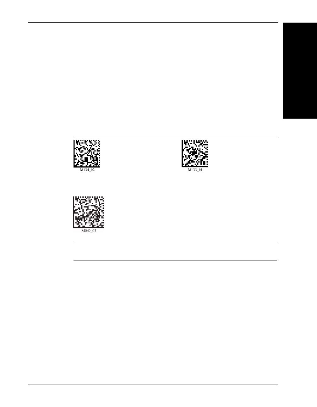
Reset Reader to Factory Defaults
Scan the codes in Figure 8–1 and Figure 8–2 to reset the reader:
FIGURE 8–1. Reset Reader to Factory Defaults Codes
8
Troubleshooting
Maintenance and
Rev 2.0.0, Jan 2009 HawkEye™ 45T User Manual 8-1
Page 84

Chapter 8 Maintenance and Troubleshooting
Clear All CodeXML
Rules
Prefix & Suffix
Clear All
Stored Data
Save Settings
Warning
Charge the Lithium Ion Battery in the BH1/BH2 with Microscan’ cables
ONLY. Do not open battery, dispose of in fire, or short circuit; it may ignite,
explode, leak, or get hot, causing personal injury.
FIGURE 8–2. Reset Reader to Factory Defaults Codes (Continued)
Note: If you scan the codes in Figure 8–1 and Figure 8–2, you may lose your
current settings. Therefore, make sure you save settings on your reader before
scanning the codes in Figure 8–1 and Figure 8–2.
General Safety Information
Repairs and Adjustments — Only those individuals authorized by Microscan
should attempt to make repairs or adjustments to HE45T equipment. If the reader
casing is opened, the warranty is voided.
Power Supply — Use only the particular power supply provided for use with a
specific reader when operating Microscan equipment.
Accessories — Only those accessories approved by Microscan should be utilized
with Microscan equipment. Non-compliance with any of the above may result in:
• Injury to individuals handling the equipment
• Damage to the equipment
• Voiding of the maintenance contract
Bootloader mode is utilized to download new versions of bootloader firmware
and custom applications.
Lasers — The HE45T utilizes a laser FOR TARGETING PURPOSES ONLY. If
the laser is activated, do not stare into the beam.
8-2 HawkEye™ 45T User Manual Rev 2.0.0, Jan 2009
Page 85

HE45T Accessories
Please call your Microscan representative for more information on accessories.
HE45T Maintenance
The HE45T operates efficiently and reliably and needs only a minimum of
maintenance to operate. A few tips are given below for maintenance suggestions.
Cleaning the HE45T’s Window
The HE45T’s window should be clean to allow the best performance. The
window is the clear plastic piece inside the head of the Reader. Do not touch the
window. Your HE45T uses CMOS technology that is much like a digital camera.
A dirty window may stop the HE45T from reading codes.
If the window becomes dirty, clean it with a soft, non-abrasive cloth or a facial
tissue (no lotions or additives) that has been moistened with water. You may use a
mild detergent to clean the window, but the window should be wiped with a
water moistened cloth or tissue after using the detergent.
HE45T Accessories
8
Troubleshooting
Maintenance and
The HE45T’s display screen and housing may be cleaned in the same way.
For applications that require cleaning with disinfectant, please use products with
the following ingredients:
• Isopropyl Alcohol
• Ethyl Alcohol (Denatured Grade)
Microscan does not recommend using bleach.
Rev 2.0.0, Jan 2009 HawkEye™ 45T User Manual 8-3
Page 86

Chapter 8 Maintenance and Troubleshooting
8-4 HawkEye™ 45T User Manual Rev 2.0.0, Jan 2009
Page 87

A
Reset to USB Factory Defaults Settings
APPENDIX A Programming Codes for
Alternate OS Compatibility
Use the following procedure to program the HE45T to work with the Mac
platform, running under OS X:
1. Scan the code Figure A–1 to restore USB factory default settings:
FIGURE A–1. Reset to USB Factory Defaults Code
2. Scan the three programming codes (Figure A–2) in the following order:
– Microsoft Windows CE, Linux, Mac OS X code
A
for Alternate OS
Programming Codes
– USB Keyboard Mode code
– Save Settings code
Rev 2.0.0, Jan 2009 HawkEye™ 45T User Manual A-1
Page 88

Appendix A Programming Codes for Alternate OS Compatibility
USB Keyboa rd Mode
Save Settings
Microsoft Windows CE, Linux, Mac OS X
FIGURE A–2. Scan Codes in order, top to bottom
3. Cycle the power on the HE45T by removing and re-installing the battery in
the unit.
A-2 HawkEye™ 45T User Manual Rev 2.0.0, Jan 2009
Page 89

4. Plug the USB cable into the Mac processor (not the keyboard). The screen in
Figure A–3 is displayed:
FIGURE A–3. Keyboard Setup Assistant Screen - Introduction
A
for Alternate OS
Programming Codes
Rev 2.0.0, Jan 2009 HawkEye™ 45T User Manual A-3
Page 90

Appendix A Programming Codes for Alternate OS Compatibility
5. Click Continue. The screen Figure A–4 is displayed:
FIGURE A–4. Keyboard Setup Assistant Screen - Identifying Keyboard
A-4 HawkEye™ 45T User Manual Rev 2.0.0, Jan 2009
Page 91

6. Scan the code in Figure A–5:
FIGURE A–5. Code
The screen in Figure A–6 is displayed:
FIGURE A–6. Keyboard Setup Assistant Screen - Cannot Identify Keyboard
A
for Alternate OS
Programming Codes
Rev 2.0.0, Jan 2009 HawkEye™ 45T User Manual A-5
Page 92

Appendix A Programming Codes for Alternate OS Compatibility
7. Click OK. The Select the Keyboard Type screen is displayed:
FIGURE A–7. Keyboard Setup Assistant Screen - Select Keyboard Type
8. Select ANSI and then click Done.
You are now ready to scan codes in using Mac OS X.
A-6 HawkEye™ 45T User Manual Rev 2.0.0, Jan 2009
Page 93

B
APPENDIX B Certification and
Specifications
CE Compliance
The HawkEye™ 45T has been certified to conform to the requirements of
Council Directives 89/336/EEC, 73/23/EEC, and 1999/5/EC to comply with the
following European Standards:
B
• EN 60950-1:2001 Low Voltage/Safety
• EN 300 238-2(2000-07) Radio
• EN 55022:1994 Class B Radiated Emissions, and
Class B Conducted Emissions
• EN 55024:1998 EMC Immunity Requirements
• EN 61000-4-2 ESD
• EN 61000-4-3 Radiated RF Immunity
• EN 61000-4-4 EFT
• EN 61000-4-5 Surge
• EN 61000-4-6 Conducted RF Immunity
• EN 61000-4-8 Magnetic Fields
• EN 61000-4-11 Line Interruption
Rev 2.0.0, Jan 2009 HawkEye™ 45T User Manual B-1
Specifications
Certification and
Page 94

Appendix B Certification and Specifications
All Microscan products bearing the CE mark have been declared to be in
conformance with the applicable EEC Council Directives. However, certain
factory installed options or customer requested modifications may compromise
electromagnetic compatibility and prohibit use of the CE mark. Note that the use
of interconnect cables that are not properly grounded and shielded may affect CE
compliance. For further information regarding CE Compliance, see “Service &
Support on the Internet” on page xi.
FCC Statement
The HawkEye™ 45T has been tested for compliance with FCC regulations and
was found to be compliant with all applicable FCC Rules and Regulations
This equipment has been tested and found to comply with the limits for a Class B
digital device, pursuant to Part 15 of the FCC Rules. These limits are designed to
provide reasonable protection against harmful interference when the equipment
is operated in a commercial environment. This equipment generates, uses, and
can radiate radio frequency energy and, if not installed and used in accordance
with the instruction manual, may cause harmful interference to radio
communications. Operation of this equipment in a residential area is likely to
cause harmful interference, in which case you will be required to correct the
interference at your own expense. Changes or modifications not expressly
approved by the party responsible for compliance could void your authority to
operate the equipment.
Important Note: To comply with FCC RF exposure compliance requirements,
this device must not be co-located or operate in conjunction with any other
antenna or transmitter.
B-2 HawkEye™ 45T User Manual Rev 2.0.0, Jan 2009
Page 95

FDA Statement
Caution
Laser in the HE45T
LASER RADIATION - AVOID LONG TERM VIEWING OF DIRECT
LASER RADIATION - LASER CLASS 2M
Wavelength 630 nm - Maximum radiant power: < 1mW
EN 60825-1:2003
This equipment complies with
US21 CFR Subchapter J Part 1040.10
EN 60950-1:2001
FDA Statement
The HawkEye™ 45T can be set to use targeting lasers. If the targeting lasers are
activated, do not stare into the beams. The HawkEye™ 45T’s targeting lasers
have been rated as Class 2M Lasers by IEC 60825-1
Safety Guidelines
Important Note: LED Lighting
Light Emitting Diode Class 1 according to EN 60825-1:2003
B
Specifications
Certification and
Rev 2.0.0, Jan 2009 HawkEye™ 45T User Manual B-3
Page 96

Appendix B Certification and Specifications
Specifications
HawkEye™ 45T
Physical Characteristics
Reader Dimensions: 1.6” H x 4.4” D x 1.8” W
(4.1cm H x 11.0cm D x 4.6cm W)
Handle Dimensions: 4.6” H x 3.8” L x 1.9” W
(11.6cm H x 9.7cm L x 4.9cm W)
Reader Weight w/Battery:6.0 oz (172 gm)
Battery Weight: 2.1 oz (60 gm)
Handle Weight: 2.1 oz (60 gm)
Performance Characteristics
Power Requirements: Reader @ 4.2Vdc –
Peak (w/backlight) = 400mA; Continuous
Scan (w/backlight) = 350mA;
Idle (no backlight) = 150mA; sleep = 12 mA,
Power Off = 0.5uA Bluetooth Radio @ 10m away
at 4.2V Peak (w/backlight) = 525mA;
Continuous Scan 9W/backlight) = 400mA;
Idle (no back light) = 250mA
Illumination: Embedded Class 1 LED
Field of View: Near: 1.0” H x 1.5” W (2.5cm H x 3.8cm W) at
focal point
Far: 2.5” H x 4.0” W (6.4cm H x 10.2cm W) at
focal point
Focal Point: Near: approximately 4” (10.2cm)
Far: approximately 9” (22.9cm)
Sensor: Progressive Scan CMOS 1.33 MP (1024x1280)
256 level gray scale
Optical Resolution: Near Field: 1024 x 640 pixels
Far Field: 1024 x 640 pixels
Pitch: ± 60º (from front to back)
B-4 HawkEye™ 45T User Manual Rev 2.0.0, Jan 2009
Page 97

Specifications
Skew: ± 60º from plane parallel to symbol (side-to-side)
Rotational Tolerance: ± 180º
Target Beam: Class 2M Visible Laser Diode at 630 nm
Ambient Light Immunity: Sunlight: Up to 9,000ft-candles/98,890 lux
Shock: Withstands multiple drops of 4 feet
(1.2 meters) concrete
Optional Cable Interfaces: USB (Full Speed), RS-232 & PS/2
Memory: 4MB of memory for data and user programs
Programming: Use programming Data Matrix code
User Environment
Operating Temperature: 0° C to 40° C, 32° F to 104° F
Storage Temperature: -20° C to 60° C, -4° F to 140° F
Humidity: 5% to 95% non-condensing
Decode Capability: Data Matrix, PDF417, QR Code,
MicroQR Code, Code 39, Code 128,
UPC/EAN/JAN, Int 2 of 5, Codabar, Code 93
Image Output Options: JPEG or BMP (Uncompressed)
Field Selection: Near or Far
Resolution Selection: SXGA (1024 x 640)
Real Time Clock: 7 year On-Board Battery Backup
B
Specifications
Certification and
Rev 2.0.0, Jan 2009 HawkEye™ 45T User Manual B-5
Page 98

Appendix B Certification and Specifications
B-6 HawkEye™ 45T User Manual Rev 2.0.0, Jan 2009
Page 99

Index
Numerics
12-character Bluetooth Address 1-24
A
All 1D Bar Codes 3-7
Auto
connect
disconnect 1-28
B
Backlight
intensity settings
timeout settings 5-2
Bar Codes
all 1d
Batch Operation 1-13
Battery
charging
type 1-13
Baud Rate Settings 1-23
Bluetooth
address
radio
1-28
5-2
3-7
1-13
1-24
auto connect 1-28
auto disconnect 1-28
operation 1-24
out of range notification settings 1-30
range 1-25
timeout settings 1-29
transferring data 1-25
C
Cable
installing
ps2 1-19
rs-232 1-21
usb 1-17
Cabled Operation 1-16
Certification A-1, B-1
Charging the Battery 1-13
Class 1 Device 1-25
Codabar Symbology 3-3
Code
128 symbology
3-4
39 symbology 3-3
93 symbology 3-4
Codes
backlight
intensity 5-2
timeouts 5-2
bluetooth radio
auto connect 1-28
auto disconnect 1-28
disconnect 1-27
out of range settings 1-30
timeout settings 1-29
cabled reader
timeout settings 1-24
clear all codexml rules 3-1
codabar 3-3
code 128 3-4
code 39 3-3
code 93 3-4
continuous scan
duplicate scan delay 2-5
sleep timeout 2-4
trigger delays 2-5
enable all 1d codes 3-7
erase prefix & suffix data 7-4
Rev 2.0.0, Jan 2009 HawkEye™ 45T User Manual Index-1
Page 100

Index
factory defaults
reset to ps2 1-21, 3-1
reset to rf 1-25, 3-1
reset to rs-232 3-1
reset to usb 3-1
handle trigger 2-3
interleaved 2 of 5 3-5
keyboard 5-5
time stamp settings 5-7
laser 5-3
left trigger 2-2
motion detection scan settings 2-5
pdf 417 3-5
power off settings 5-3
prefix 7-1
ps2 1-21
qr code 3-6
reader
id & firmware version 5-4
settings locked & unlocked 5-5
reset to usb factory defaults 1-19
rf
one way mode max range 1-26
one way mode max reliability 1-26
two way mode 1-26
right trigger 2-2
rs-232
batch cable detect 1-15
cabled - no power 1-15
one way mode 1-22
suffix 7-3
turbo dot peen mode 6-1
upc/ean/jan 3-7
usb
downloader 1-19
keyboard 1-18, 1-19
native two way 1-19
virtual com 1 way 1-19
vibration 5-1
volume 5-1
Communication
mode icons
1-6
settings
ps2 1-21
Connection Icons 1-5
Continuous
scan
2-3
duplicate scan delay 2-5
sleep timeout 2-4
trigger delays 2-5
D
Data Bit Settings 1-22
Device
disconnecting
1-27
reconnecting 1-27
Disconnecting
device
1-27
DoD UID 4-1
Duplicate Scan Delay 2-5
E
Erase Prefix and Suffix Settings 7-4
F
Factory Defaults
reset reader to
8-1
Far Field 2-1
G
General Safety Information 8-2
H
Handle
attaching
1-8, 1-10
HE45T
maintenance
8-3
pre-configured with sxga 2-1
with attachable handle 1-16
I
Icon
combinations
1-31
overview 1-3
Icons 1-5
connection 1-5
input mode 1-7
memory 1-7
packet mode 1-6
power 1-5
Imager
field of view
1-37
resolution 1-37
Input Mode Icons 1-7
Index-2 HawkEye™ 45T User Manual Rev 2.0.0, Jan 2009
 Loading...