

Microscan HawkEye 1500 User Manual

HawkEye™ 1500 Series
User Manual
v2.4.1, Nov 2008
EM-40391-1V241

Copyright and Disclaimer
Copyright ©2008 by Microscan Systems, Inc.
1201 S.W. 7th Street, Renton, WA, U.S.A. 98057
(425) 226-5700 FAX: (425) 226-8682
All rights reserved. The information contained herein is proprietary and is provided solely for the purpose of allowing
customers to operate and/or service Microscan manufactured equipment and is not to be released, reproduced, or used
for any other purpose without written permission of Microscan.
Throughout this manual, trademarked names might be used. Rather than place a trademark (™) symbol at every
occurrence of a trademarked name, we state herein that we are using the names only in an editorial fashion, and to the
benefit of the trademark owner, with no intention of infringement.
Disclaimer
The information and specifications described in this manual are subject to change without notice.
Latest Manual Version
For the latest version of this manual, see the Download Center on our web site at: www.microscan.com.
Technical Support
For technical support, email: helpdesk@microscan.com.
Microscan Systems, Inc.
1201 S.W. 7th Street
Renton, WA 98057
U.S.A.
Tel: 425 226 5700
Fax: 425 226 8250
helpdesk@microscan.com
Microscan Europe
Tel: 31 172 423360
Fax: 31 172 423366
Microscan Asia Pacific
R.O. Tel: 65 6846 1214
Fax: 65 6846 4641
Microscan Limited Warranty Statement and Exclusions
What Is Covered?
Microscan Systems Inc. warrants to the original purchaser that products manufactured by it will be free from defects in
material and workmanship under normal use and service for a period of one year from the date of shipment. This
warranty is specifically limited to, at Microscan’s sole option, repair or replacement with a functionally equivalent unit
and return without charge for service or return freight.
What Is Excluded?
This limited warranty specifically excludes the following: (1) Any products or parts that have been subject to misuse,
neglect, accident, unauthorized repair, improper installation, or abnormal conditions or operations; (2) Any products or
parts that have been transferred by the original purchaser; (3) Customer mis-adjustment of settings contrary to the
procedure described in the Microscan Systems Inc. owners manual; (4) Upgrading software versions at customer request
unless required to meet specifications in effe ct at the time of purchase; (5) Units returned and found to have no failure
will be excluded; (6) Claims for damage in transit are to be directed to the freight carrier upon receipt. Any use of the
product is at purchaser’s own risk. This limited warranty is th e only warranty provided by Microscan Systems Inc.

regarding the product. Except for the limited warranty above, the product is provided “as is.” To the maximum extent
permitted by law, this ex press warranty excludes all other warranties, express or implied, including but not limited to,
implied warranties of merchantability and. Technical support questions may be directed to: helpdesk@microscan.com
Register your product with Microscan: www.microscan.com/register fitness for a particular purpose. Microscan Systems
Inc. does not warrant that the functions contained in the product will meet any requirements or needs purchaser may
have, or that the product will operate error free, or in an uninterrupted fashion, or that any defects or errors in the product
will be corrected, or that the product is compatible with any particular machinery.
Limitation of Liability
In no event shall Microscan Systems Inc. be liable to you or any third party for any special, incidental, or consequential
damages (including, without limitation, indirect, special, punitive, or exemplary damages for loss of business, loss of
profits, business interruption, or loss of business information), whether in contract, tort, or otherwise, even if Microscan
Systems Inc. has been advised of the possibility of such damages. Microscan Systems Inc.’s aggregate liability with
respect to its obligations under this warranty or otherwise with respect to the product and documentation or otherwise
shall not exceed the amount paid by you for the product and documentation. Some jurisdictions do not allow the
exclusion or limitation of incidental or consequential damages or limitations on an implied warranty, so the above
limitation or exclusion may not apply to you. This warranty gives you specific legal rights, and you may also have other
rights which may vary from state to state.
Tel: 425.226.5700 | Fax: 425.226.8250 | helpdesk@microscan.com


Contents
PREFACE Welcome! xv
Purpose of This Manual xv
Manual Conventions xv
CHAPTER 1
Configurations 1-1
Selecting the Correct HawkEye™ to Read Your Data Matrix 1-1
Data Matrix Construction 1-3
Selection Criteria 1-4
Resolution 1-4
Field of View 1-4
Working Distance 1-5
Selecting A Lens 1-5
Standard Lens Selection Chart 1-5
Custom Lens Selection 1-6
Selecting Lighting 1-6
Standard Light Selection 1-6
HawkEye™ 1515 1-7
HawkEye™ 1525 1-8
HawkEye™ XL details 1-8
Custom Light Selection 1-9
HawkEye™ 1510 1-9
v2.4.1, Nov 2008 HawkEye™ 1500 Series User Manual v

Contents
CHAPTER 2 Connecting to the HawkEye™ 1500 2-1
Connectivity 2-1
TCP/IP P o rt 2- 1
Serial Port 2-3
Rear Panel 2-4
Power Connector 2-5
Power Supply Wiring 2-6
Field I/O Connector 2-8
Grounding Tab (Optional) 2-11
I/O Expansion Module (Optional) 2-13
Using the I/O Expansion Module 2-14
I/O Expansion Module Connectors 2-16
I/O Interface Connector – J1 2-16
Opto In, Opto Out, & Strobe Output Terminal Block – TB1 2-17
General Purpose I/O Terminal Block – TB2 2-19
Field I/O Wiring Examples 2-20
Input Opto Wiring 2-20
Output Opto Wiring 2-21
General Purpose I/O Wiring 2-24
External I/O Terminal Block Adapter (Option al) 2-27
External I/O Terminal Block Connectors 2-27
I/O Interface Connector – (15 Connector HDB-Sub) 2-27
Signal Distribution Terminal Block 2-28
Field I/O Wiring Examples 2-30
Input Opto Wiring 2-30
Output Opto Wiring 2-31
TTL I/O Wiring 2-33
External I/O Terminal Block Adapter Cable (Optional) 2-34
External Strobe & Sensor 2-36
Serial Connector & Serial Adapter Cable 2-39
Ethernet 2-41
Power & Ethernet LEDs 2-42
Mode/Status LEDs 2-43
Verification LEDs 2-44
Beeper 2-44
QuicSet® 2-44
Front Panel HawkEye™ 1510 2-45
Light Port Connector 2-45
vi HawkEye™ 1500 Series User Manual v2.4.1, Nov 2008

Mounting Blocks 2-47
Optional Location for Mounting Block 2-47
CHAPTER 3 HawkEye™ 1500 Series Overview 3-1
Unique Camera Names 3-3
Application Modes 3-3
Demo 3-3
Motion 3-4
Stop and Scan 3-4
Supermarket 3-4
Lighting Modes 3-4
Retry Modes 3-6
Time 3-7
Count 3-7
GPIO IN 4 Duration 3-7
ISWT (Inter-Symbol Wait) 3-8
PID List 3-9
PID List w/Acquire 3-10
Light 3-10
HawkEye™ 1500 I/O Operations 3-10
Trigger Behavior 3-10
Trigger Diagrams 3-11
Trigger Diagram 1 3-12
Trigger Diagram 2 3-13
Trigger Diagram 3 3-14
Trigger Diagram 4 3-15
Trigger Diagram 5 3-16
Trigger Diagram 6 3-17
Triggering the Unit (Inputs) 3-17
Physical Triggers 3-18
Virtual Triggers 3-18
Additional Physical Triggers Available 3-19
Outputs 3-19
Data Valid — Pipelined 3-20
Pass/Fail Only — Pipelined 3-21
Data Valid — Full Handshake 3-22
Pass/Fail Only — Full Handshake 3-24
DV - 2 Line Verify — Full HS 3-25
DV - 3 Line Verify — Full HS 3-26
Contents
v2.4.1, Nov 2008 HawkEye™ 1500 Series User Manual vii

Contents
DV - 2 Line Verify — Pulse 3-28
DV - 3 Line Verify — Pulse 3-29
Formatted Output & Audio 3-31
Reported Error Codes 3-32
QuicSet® Symbol Photometry 3-35
CHAPTER 4
ReadRunner 4-1
Setting Up Communications 4-1
Overview 4-1
ReadRunner Menus 4-2
ReadRunner Shortcut Keys 4-4
ReadRunner Buttons 4-5
Setting Up Your Application 4-7
Adding & Taking Control of a Camera 4-7
Adding a Camera That is on a Different Subnet 4-11
Using Live Video to Align the Camera 4-12
Using Learn During Image Optimization 4-14
Displaying Camera Report Information 4-15
Resetting Camera Report Statistics 4-18
Saving & Loading Configuration Files 4-18
Saving Configuration Files 4-19
Loading Configuration Files 4-20
Releasing Control of a Camera 4-21
Removing a Camera 4-21
Using ReadRunner 4-22
Setting Up Photometry 4-22
Preprocessing Images 4-24
Setting Up Symbology 4-25
Defining the Region of Interest 4-26
Copying Current to PID 4-28
Copying PID to Current 4-28
Setting Up Text Matching 4-29
Match List Triggered I/O 4-31
Behavior of the Wildcard Match 4-40
Setting Up Serial Number Matching 4-41
Specifying... 4-44
Preferences 4-44
Application Modes 4-46
Lighting 4-48
viii HawkEye™ 1500 Series User Manual v2.4.1, Nov 2008

Retry Modes 4-49
Extended PID List 4-51
Read Timeout 4-52
Report Budget 4-52
Triggers 4-53
Advanced I/O 4-54
Supported Keyword Names 4-59
Supported Behaviors 4-61
Serial/TCP Settings 4-64
Ethernet/IP Connectivity 4-67
Output Format Strings 4-71
Format String Keywords 4-77
Keyword Example 4-82
Toggling the Target Laser 4-86
Toggling the Beeper 4-87
Controlling the Beep 4-88
Saving Parameters on the Camera to Flash 4-89
Restoring Defaults 4-89
Decoder 4-89
Application Mode 4-89
Decoder & Application Mode 4-90
Displaying... 4-90
Verification Report 4-90
Reports & Images Over A Serial Connection 4-91
Commands Sent To and Output From the Camera 4-91
Programming User Buttons 4-92
Sending Remote Commands to the Camera 4-94
Timing & Rate Information 4-94
Information About Cameras on the Network 4-96
ReadRunner Version Number 4-98
Fine Tuning & Monitoring Your Application 4-100
Selecting Symbologies (1D or 2D) 4-100
Camera Resolution and Pixels 4-100
Learning & Unlearning 4-101
Enabling Assisted Learn 4-103
Unlearning 4-103
Modifying Decoding Parameters 4-104
Data Matrix Parameters 4-104
Barcode Parameters 4-109
Expert Settings 4-113
Data Matrix Fine Tune 4-115
BC412 Parameters 4-116
QR Code Parameters 4-117
Contents
v2.4.1, Nov 2008 HawkEye™ 1500 Series User Manual ix

Contents
Code 39 Parameters 4-118
I2of5 Parameters 4-119
UPC Parameters 4-119
Debugging Images 4-120
Configuring the Part Queue 4-120
Uploading Images Using QueueView 4-126
Saving Images to the PC Using QueueView 4-128
Saving the Current Image 4-129
Loading Image Files to the Camera 4-129
Returning the Camera to Acquisition 4-130
The Filmstrip Recorder 4-131
CHAPTER 5 Reading Difficult Symbols 5-1
General Reading Guidelines 5-1
Further Explanation 5-1
Preprocessing with Morphology 5-2
Erode Example 5-3
Dilate Example 5-4
Reading Different Difficult Symbols 5-5
CHAPTER 6
The Bootloader 6-1
Diagnostic Levels 6-1
Diagnostic Monitor 6-1
Boot Loader Power-On Self-Tests 6-3
Hard Error 6-3
Bootloader Menu 6-3
d — Dump Memory 6-4
Syntax 6-4
m — Modify Memory 6-5
Syntax 6-5
dt — Display Test Menu 6-5
Syntax 6-5
et — Execute Test 6-6
Syntax 6-6
dbp — Display Boot Parameters 6-6
Syntax 6-6
mbp — Modify Boot Parameters 6-7
Standalone Mode 6-7
x HawkEye™ 1500 Series User Manual v2.4.1, Nov 2008

Syntax 6-7
Manufacturing Mode 6-8
dm — Display Menu 6-9
Syntax 6-9
dfb — Display Flash Blocks 6-10
Syntax 6-10
der — Display Ethernet Registers 6-10
Syntax 6-10
wmr — Write MAC Register 6-11
Syntax 6-11
wpr — Write PHY Register 6-11
Syntax 6-11
cpu — Display CPU Registers 6-11
Syntax 6-11
flsh — Display System Flash Size 6-12
Syntax 6-12
ram — Display System RAM Size 6-12
Syntax 6-12
cach — I-Cache Control 6-12
Syntax 6-12
x — File Transfer and Execute 6-12
r — Reset Unit 6-13
Syntax 6-13
j — Jump to Application 6-13
Syntax 6-13
e — Display Last Logged Error 6-13
Syntax 6-13
h — Display Command Help 6-13
Syntax 6-13
Diagnostic Test Menu 6-13
LEDS 6-15
Po wer-on Sequence 6-15
Error Codes 6-15
Contents
APPENDIX A HawkEye™ 1510 A-1
Optics A-2
External Lighting Mounting Options A-3
Power for Lights A-6
Options A-6
Lighting Connector A-7
v2.4.1, Nov 2008 HawkEye™ 1500 Series User Manual xi

Contents
APPENDIX B Troubleshooting & Frequently Asked Questions B-1
Frequently Asked Questions B-1
My camera is connected to the network and serial port, but I have no
idea what the current communication settings are. How do I figure it
out? B-1
I have DHCP activated, b ut the camera reports a 169.254.x.x address.
What’s happening? B-2
How can I tell if the IP configuration of my PC and my camera are
valid? B-3
How do I restore the camera to factory defaults? B-3
When should I use DHCP? B-3
I have no idea what the current settings are for the camera. What do I
do? B-4
What if Learn succeeds but read fails? B-4
My decode data is very long. Is there a way to disable the sending of
this data on the serial port? B-4
A connection has taken control of my camera and I can’t regain control.
Is there a way to break this control so I can get it back? B-5
When I disconnect the network cable from the PC while the camera is
under control by ReadRunner, reconnecting the network cable will not
allow ReadRunner to take control again. What do I do? B-5
I had control of the camera over the serial port and left the machine for
a few minutes. When I came back, the camera was no longer under
control. What happened? B-5
I’m using the Part Queue to record images on the camera but, after a
while, the camera runs much slower. What’s going on? B-6
Do the version numbers have to match? B-6
What’s the timing for normal strobe and power strobe? I’m assuming
that both strobe modes would go off immediately after the trigger (or
the configured delay) and then stay on for some fixed duration? Is that
correct? What's the duration? Is the duration different for each strobe
mode? B-6
Is the “Exposure” in the Photometry dialog and command the same as
the “Shutter” on the HawkEye™ 15? B-7
What exactly happens with auto photometry when using a sensor as a
trigger? The HawkEye™ has only one chance to get an image, so I can
only imagine that the settings are adjusted after each image, hoping
that the adjustment will be appropriate for the next part. Am I
correct? B-7
I’m trying to re-install all my computer software after it was attacked by
a virus. When I run the ReadRunner install, neither the “Repair” option
xii HawkEye™ 1500 Series User Manual v2.4.1, Nov 2008

nor the “Remove” option seems to do anything. How can I re-install
ReadRunner once this happens? B-7
Sometimes, when using a Logitech mouse and scrolling with the
wheel, I see crashes in ReadRunner especially in the Network
Overview form. What can I do to fix this behavior? B-8
Trouble Reading B-8
Setting the HawkEye™ 1500 to Factor y Default Settings B-8
Samples of Reader Programming Data Matrices B-8
Setting Serial Communications B-8
Setting Triggers B-9
Resetting B-9
Setting Targeting B-9
Setting Beeper B-9
Setting Illumination B-9
Resetting ROI B-9
Setting Learn/Unlearn B-10
Setting Photometry B-10
Saving B-10
Setting DHCP B-10
Contents
APPENDIX C Upgrading Camera Software C-1
Overview C-1
Using HawkEye™ Bootloader C-2
Using HawkEye™ Flasher C-5
APPENDIX D
Symbology Reference D-1
Data Matrix D-1
Data Matrix Certification D-1
What Is Data Matrix? D-1
Data Matrix Components D-3
Data Matrix Error Correction D-5
Bit Versus Codeword D-6
Data Matrix Encoding Schemes D-7
ECC 000-140 D-7
ECC 200 D-8
Data Matrix Specification Details D-9
Summary of Additional Features D-11
Symbol Structure D-11
v2.4.1, Nov 2008 HawkEye™ 1500 Series User Manual xiii

Contents
Creating a Data Matrix D-12
Reader Programming Data Matrix D-13
Symbol Samples D-14
2-D Symbols D-14
Data Matrix (Data “123456789”) D-14
PDF417 (Data “PDF417 sample”) D-14
1-D Symbols D-14
Code 128 (Data “This is Code 128”) D-14
Code 93 (Data “1234 CODE 93”) D-14
Code 39 (Data “ABCD CODE 39”) D-15
Interleaved 2 of 5 (Data “25251234567890”) D-15
Codabar (Data “1234567890”) D-15
EAN 13 (Data=“9876543210999” D-15
EAN 8 (Data “76543210”) D-15
UPC A (Data “98765432109”) D-16
5-Digit Postnet with Check Character (Data “020215”) D-16
SEMI BC412 with Both Start/Stop & Checksum D-16
Pharmacode (Data “399”) D-16
APPENDIX E Specifications E-1
HawkEye™ 1500 Dimensions E-2
APPENDIX F
Custom Programming Using a Serial Connection F-1
Code Walkthrough F-2
Complete Source Code F-4
Index Index-1
xiv HawkEye™ 1500 Series User Manual v2.4.1, Nov 2008

Preface
PREFACE Welcome!
Purpose of This Manual
This manual is designed to help you to understand how your HawkEye™ 1500
works, and how to use it quickly and efficiently.
Manual Conventions
The following typographical conventions are used throughout this manual.
• Items emph asizing important information is bolded.
• Menu selecti ons, menu items and ent ries in screen images are indicated as:
Run (triggered), Modify..., etc.
v2.4.1, Nov 2008 HawkEye™ 1500 Series User Manual xv

Preface
xvi HawkEye™ 1500 Series User Manual v2.4.1, Nov 2008

1
CHAPTER 1 Configurations
This chapter contains information about selecting the proper HawkEye™ 1500
Series Smart Camera-Based Reader for your application. It also contains
information about selecting lenses and lighting.
1
Configurations
Note: Throughout this manual, “HawkEye™ 1500 Series Camera” is used as a
generic term for the HawkEye™ 1515, the HawkEye™ 1525, and the
HawkEye™ 1510. When information is specific to a camera, that camera name is
used.
Selecting the Correct HawkEye™ to Read Your Data Matrix
There are three main HawkEye™ models:
v2.4.1, Nov 2008 HawkEye™ 1500 Series User Manual 1-1
Chapter 1 Configurations
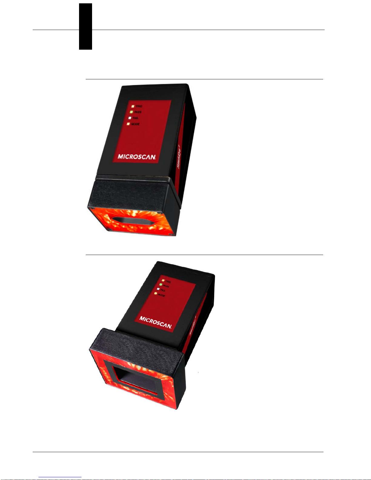
FIGURE 1–1. HawkEye™ 1515
FIGURE 1–2. HawkEye™ 1525
1-2 HawkEye™ 1500 Series User Manual v2.4.1, Nov 2008
Selecting the Correct HawkEye™ to Read Your Data Matrix
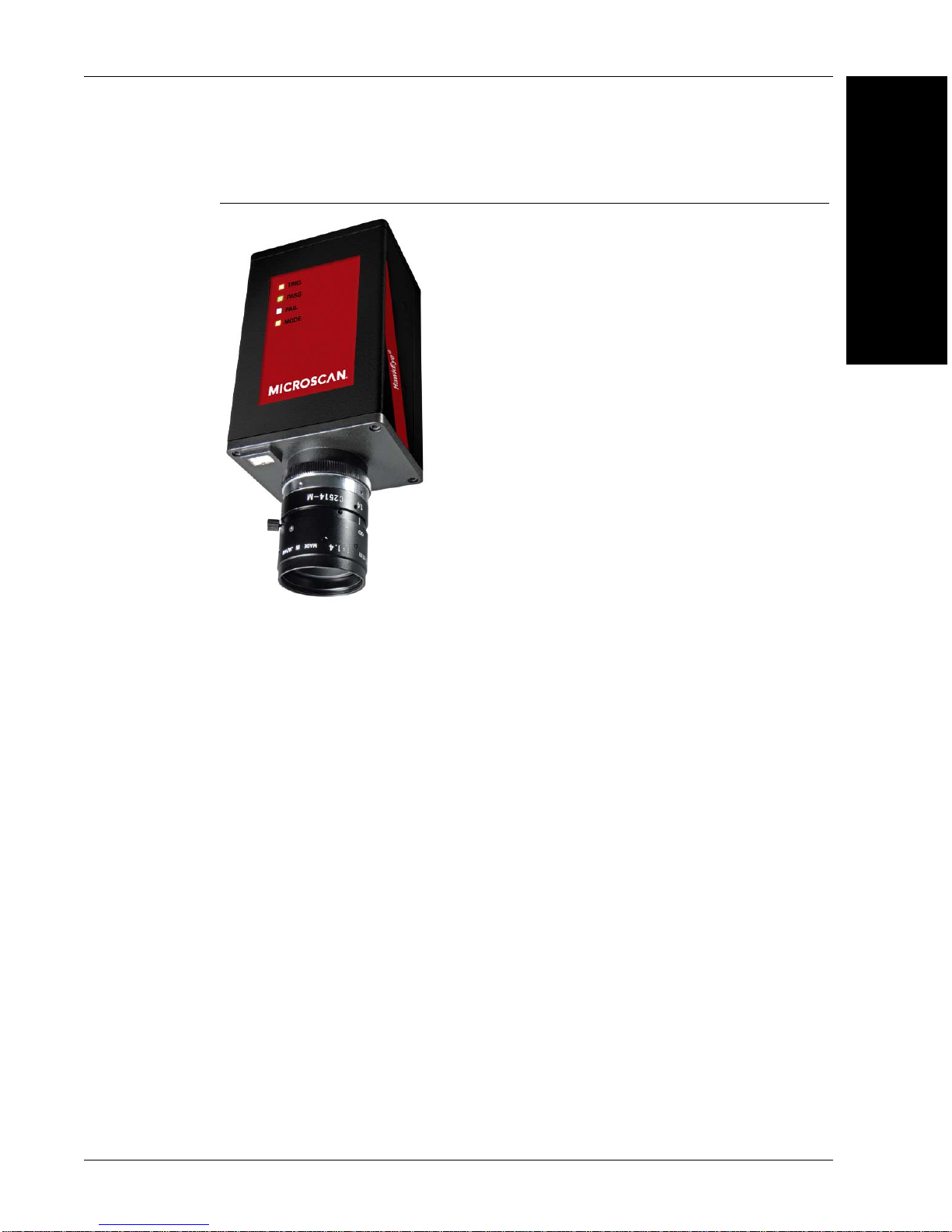
FIGURE 1–3. HawkEye™ 1510
1
Configurations
Both the HawkEye™ 1515 and HawkEye™ 1525 have fixed optics and
illumination built right into the units. The HawkEye™ 1510 allows you to select
from a variety of off-the-shelf optics and illumination components. For complete
information about the HawkEye™ 1510, see Appendix A, “HawkEye™ 1510,”.
The HawkEye™ 1515 and HawkEye™ 1525 use the same lenses, which give the
units a range of magnifications. The HawkEye™ 1515 and HawkEye™ 1525 use
different illumination components.
Use the following paragraphs to help you pick the correct model and
magnification for your Data Matrix or Barcode reading application.
Data Matrix Construction
A Data Matrix is made up of four major components, as shown in Figure 1–4.
v2.4.1, Nov 2008 HawkEye™ 1500 Series User Manual 1-3

Chapter 1 Configurations
Solid Border
Quiet Zone
Timing Border
Data Storage
FIGURE 1–4. Four Major Components of a Data Matrix
Selection Criteria
There are three main considerations for choosing the proper HawkEye™ type:
• Resolution
•Field of View
• Working Distance
The most important consideration is Resolution. All three of these features are
governed by lens selection.
Resolution
A Data Matrix is comprised of a series of dark and light cells. To obtain optimal
READ performance, each cell should be imaged by at least 4 to 5 camera pixels.
To obtain optimal VERIFICATION performance, each cell should be imaged by
at least 10 camera pixels.
A Barcode is comprised of a series of light and dark lines. T o obtain optimal
READ performance, each line should be seen as at least 2 pixels wide.
Field of View
A second and interrelated consideration is Field of View. The field of view
should be small enough for the Data Matrix to have at least 4 pixels per cell
resolution. At the same time, the field of view should be large enough to contain
the Data Matrix or Barcode, as well as to leave enough space around the symbol
to compensate for symbol positioning error and the required Quiet Zone.
Note: The Quiet Zone must be at least 1 cell in size. A Quiet Zone of 2 cells or
1-4 HawkEye™ 1500 Series User Manual v2.4.1, Nov 2008
more is allowed, and makes reading easier.

Selecting the Correct HawkEye™ to Read Your Data Matrix
Working Distance
The Working Distance is the distance from the front of the light to the symbol.
Typically, it is dictated by whatever clearance is required for part handling
between the HawkEye™ 1500 camera and the part. These standoff distances vary
from a low of 3 inches (76.2mm) to a high of 5 inches (127mm) with the
HawkEye™ 1515 and the HawkEye™ 1525. If you have different standoff
distance requirements, the HawkEye™ 1510 camera should be used.
Selecting A Lens
Standard Lens Selection Chart
Table 1–1 shows the different magnifications for the HawkEye™ 1515 and
HawkEye™ 1525 with built in lenses. Each type has a specific Working
Distance, Field of View, and Minimum Cell Size. To determine the correct type:
1
Configurations
1. Determine the Cell Size for your Data Matrix. Do this by measuring the size
of your Data Matrix in the horizontal direction, and by counting the number
of cells in the horizontal direction.
Cell Size = Matrix Size (H) / Number of Cells (H)
2. Determine the overall field of view required to contain the Data Matrix,
Quiet Zone, and to allow for the positioning of the symbol.
3. Look in the chart to see which types have a Minimum Cell Sizes less than
your cell size.
Example: Assume a Data Matrix has 23 cells in the horizontal direction, is
0.75” (19.05mm) wide, and with a quiet zone, is over 1.125” (28.58mm)
wide.
0.75” (19.05mm)
Cell Size = --------------------- = 0.033” (0.84mm)
23
The only HawkEye™ Type that has a Minimum Cell Size less than 0.033”
(0.84mm) and a field of view greater than 1.125” (28.58mm) is the Medium
Density (MD).
v2.4.1, Nov 2008 HawkEye™ 1500 Series User Manual 1-5

Chapter 1 Configurations
TABLE 1–1. Lens Selection Chart
Working
Type
Medium Density (MD) 5.0” (127mm)
High Density (HD) 3.0” (76.2mm)
Long High Density
(LHD)
Super High Density
(SHD)
Ultra High Density
(UHD)
Distance
± 1.0” (25.4mm)
± 0.5” (12.7mm)
5.0” (127mm)
± 0.5” (12.7mm)
3.5” (88.9mm)
± 0.5” (12.7mm)
2.25” (57.15mm)
± 0.125”
(3.175mm)
Field of View
at Focus
1.55”H
(39.37mm) x
1.19”V
(30.23mm)
1.00”H (25.4mm)
x 0.75”V
(19.05mm)
1.00”H (25.4mm)
x 0.75”V
(19.05mm)
0.55”H
(13.97mm) x
0.42”V
(10.67mm)
0.25”H (6.35mm)
x 0.19”V
(4.83mm)
Minimum Cell Size
(4 Pixels/Cell)
DM: 0.010” (0.25mm)
BC: 0.005” (0.127mm)
DM: 0.006” (0.152mm)
BC: 0.003” (0.076mm)
DM: 0.006” (0.152mm)
BC: 0.003” (0.076mm)
DM: 0.003” (0.076mm)
BC: 0.0015” (0.038mm)
DM: 0.0013” (0.033mm)
BC: 0.0005” (0.0127mm)
Custom Lens Selection
In addition to the HawkEye™ 1515 and HawkEye™ 1525 cameras with built in
lenses, the HawkEye™ 1510 is sold with a C or CS mount that allows the use of
conventional lenses. The use of conventional lenses and extension tubes allow a
much larger range of ‘fields of view’ and ‘working distances’ to be
accomplished. Standard lens selection criteria should be employed to select the
correct optics for your application.
Selecting Lighting
Standard Light Selection
The HawkEye™ 1515 and HawkEye™ 1525 come with built in lights and built
in lenses.
1-6 HawkEye™ 1500 Series User Manual v2.4.1, Nov 2008

Selecting the Correct HawkEye™ to Read Your Data Matrix
H
a
w
k
E
y
e
T
M
28.58mm
(1.125)
57.15mm
(2.250)
22.23mm
(.875)
44.45mm
(1.750)
116.51mm
(4.587)
111.76mm
(4.400)
88.90mm
(3.500)
22.86mm
(.900)
HawkEye™ 1515
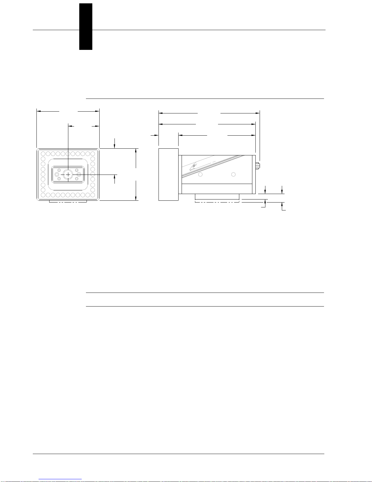
FIGURE 1–5. HawkEye™ 1515
1
Configurations
The HawkEye™ 1515 has a small light ring built on the front of the unit. The
ring is 1.75”H (44.45mm) x 1.25”H (31.75mm) at the center of the emission
zone. The ring is aimed in 15° to converge 3” (76.2mm) from the front on the
unit. When the unit is used perpendicular to the part, the light acts as a bright
field, high angle ring light. A second useful configuration is to angle the unit 20°
off of vertical. In this configuration, the light acts as a directional high angle
spotlight. The HawkEye™ 1515 configuration is the universal reader for the
broadest range of Data Matrix and Barcode reading applications.
Note: The HawkEye™ 1515-XL does not have lasers.
v2.4.1, Nov 2008 HawkEye™ 1500 Series User Manual 1-7
Chapter 1 Configurations
H
a
w
k
E
y
e
T
M
72.14mm
(2.840)
36.07mm
(1.420)
29.97mm
(1.180)
59.94mm
(2.360)
116.51mm
(4.587)
111.76mm
(4.400)
88.90mm
(3.500)
22.86mm
(.900)
6.35mm
(.250)
9.52mm
(.375)
OPTIONAL MOUNTING BLOCK
HawkEye™ 1525
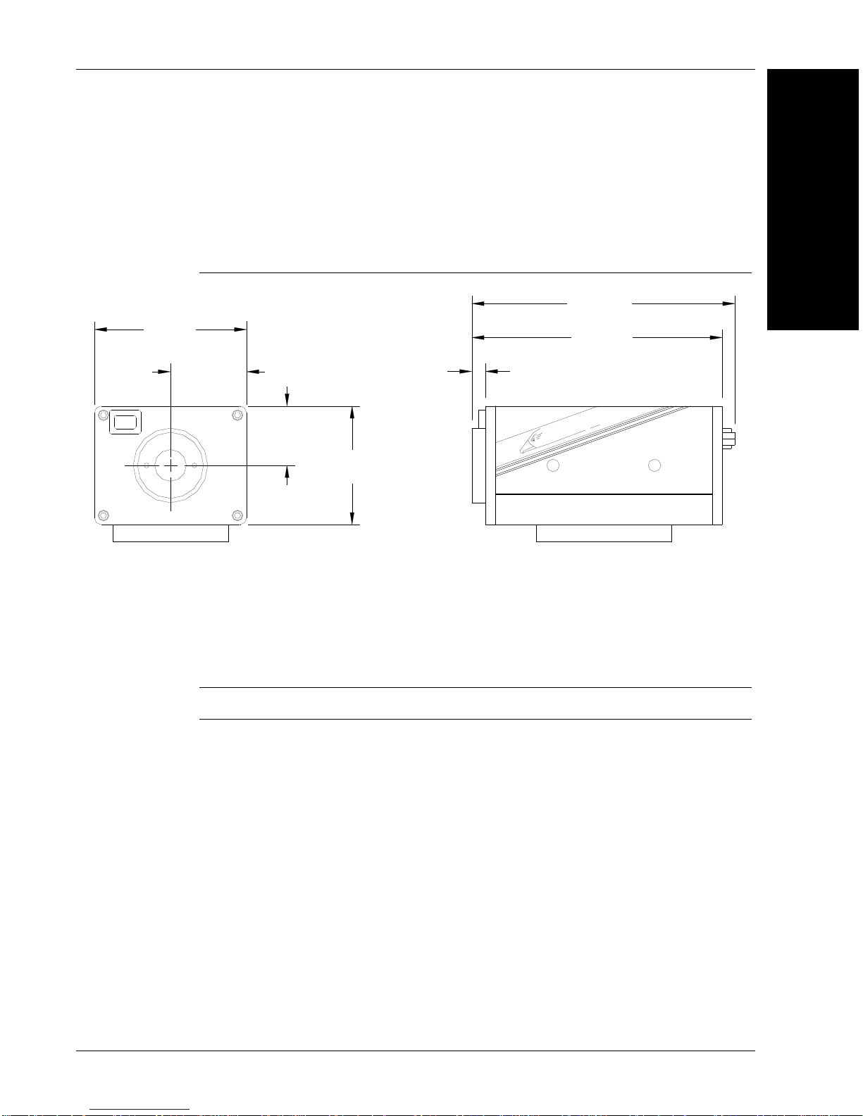
FIGURE 1–6. HawkEye™ 1525
The HawkEye™ 1525 has a medium size light ring built on the front of the unit.
The ring is 2.375”H (60.33mm) x 1.875”H (47.63mm) at the center of the
emission zone. The ring is aimed in 25° to converge 2.25” (57.15mm) from the
front on the unit. When the unit is used perpendicular to the part, the light acts as
a dark field, medium to low angle ring light. Typically, the HawkEye™ 1525 is
used for highly reflective parts.
Note: The HawkEye™ 1525-XL does not have lasers.
HawkEye™ XL details
The HawkEye™ XL is designed for applications requiring ease of integration
utilizing fixed optics and integrated lighting but does not need features/benefits
provided by laser targeting.
1-8 HawkEye™ 1500 Series User Manual v2.4.1, Nov 2008
Selecting the Correct HawkEye™ to Read Your Data Matrix
H
a
w
k
E
y
e
T
M
22.23mm
(.875)
44.45mm
(1.750)
28.58mm
(1.125)
5.08mm
(.200)
98.73mm
(3.887)
93.98mm
(3.700)
57.15mm
(2.250)
Custom Light Selection
HawkEye™ 1510
FIGURE 1–7. HawkEye™ 1510
1
Configurations
The HawkEye™ 1510 is designed for applications requiring flexibility in the
selection of lighting and optics. The unit is designed with a mounting block that
allows the attachment of C and CS mount lenses. Additionally, it has brackets
specially designed to mount a variety of the standard NER Lights. For complete
information about the HawkEye™ 1510, see Appendix A, “HawkEye™ 1510,”.
Note: The HawkEye™ 1510 does not have a laser.
v2.4.1, Nov 2008 HawkEye™ 1500 Series User Manual 1-9

Chapter 1 Configurations
1-10 HawkEye™ 1500 Series User Manual v2.4.1, Nov 2008

2
CHAPTER 2 Connecting to the
HawkEye™ 1500
The chapter contains information to help you connect to the HawkEye™ 1500
camera. Specific information describes connectors, adapters, cables, pinouts, and
signals.
2
HawkEye™ 1500
Connecting to the
Note: There are no user serviceable parts inside.
Connectivity
TCP/IP Port
When communicating over Ethernet, the camera uses the following predefined
ports. The camera establishes connections as a Server and, therefore, listens for
Host clients to initiate the connection on a particular port. Any number of clients
can connect to the camera, each one with their private peer-to-peer connection.
v2.4.1, Nov 2008 HawkEye™ 1500 Series User Manual 2-1

Chapter 2 Connecting to the HawkEye™ 1500
TABLE 2–1. HawkEye™ 1500 TCP/IP Connectivity
Port Name Protocol Number Note
Camera Query Port UDP 49093 Discovers HawkEye™ 1500 cameras on the
current subnet.
Camera Announce
Port
COMMAND TCP 49095 Used for all HawkEye™ 1500 ASCII Commands
STANDARD SERIAL N/A Programs the format of the data sent via the serial
STANDARD TCP 49096 Used by ReadRunner and programming COM
STANDARD TCP 49097 Used by ReadRunner and programming COM
TCP1 User
Connection
TCP2 User
Connection
TCP3 User
Connection
TCP4 User
Connection
UDP 49094 Broadcasts the HawkEye™ 1500 camera identity
on the current subnet used by Network View in
ReadRunner, provides general counters, camera
name, IP, IP in control, camera status, and
camera software version and capability.
including accessing Buffered cycle read reports
(PARTQ commands).
port.
object library for reports with images. By default
lossy up to 2 per second. Connection can be
programmed to lossless, i.e., inline with the read
cycle.
object library for reports only. By default lossy but
at maximum network rate. Connection can be
programmed to lossless, i.e. inline with the read
cycle.
TCP 49098 User format configurable TCP based connection.
Uses ASCII and binary keywords (IDxx), (CDxx),
etc…. Note that the connection is always
lossless, i.e., inline with the read cycle.
TCP 49099 User format configurable TCP based connection.
Uses ASCII and binary keywords (IDxx), (CDxx),
etc… Note that the connection is always lossless,
i.e. inline with the read cycle.
TCP 49100 User format configurable TCP based connection.
Uses ASCII and binary keywords (IDxx), (CDxx),
etc… Note that the connection is always lossless,
i.e., inline with the read cycle.
TCP 49101 User format configurable TCP based connection.
Uses ASCII and binary keywords (IDxx), (CDxx),
etc…
2-2 HawkEye™ 1500 Series User Manual v2.4.1, Nov 2008

Note: Ports COMMAND, TCP1…4 use a protocol that is either ASCII or defined
by you at connection time. Therefore, these ports are fully supported on a nonWindows based Host, provided the Host supports TCP/IP and a socket level API.
Ports 49096 and 49097 use a binary format that is parsed into easy to use COM
events and objects on the Host and is, therefore, only applicable to Windowsbased Hosts.
Note: You can enable/disable the UDP protocol through the command line. For
more information, see the UDP_BROADCAST command in the HawkEye 1500
Series Reference & Programmers Manual.
Serial Port
When communicating over a serial line, you need to be aware of the limitations
of this communication medium and how ReadRunner and the camera handle it.
Connectivity
2
HawkEye™ 1500
Connecting to the
There can be only one client connected to the camera. In addition, there can be
only one channel to exchange data, i.e., commands and binary data.
The ReadRunner UI enables a special ACK scheme that may need to be disabled
once the camera has been programmed and is connected serially to a PLC or the
controlling host. You can accomplish this by sending special control characters
(see Table 2–2):
TABLE 2–2. Serial Port Connectivity
Control Char Function
Ctrl+O Turn off report output.
Ctrl+P Toggle the state of the prompt and echo.
Ctrl+Q Turn off command output.
Ctrl+R Release control of the unit and put it back online.
Ctrl+S Take control of the unit and bring it offline (forcibly).
Ctrl+T Dump the heartbeat string to the terminal.
Ctrl+U Toggle the display of report strings on the terminal.
Ctrl+W Turn on command output.
v2.4.1, Nov 2008 HawkEye™ 1500 Series User Manual 2-3

Chapter 2 Connecting to the HawkEye™ 1500
Power Connector
Ethernet Connector
Power ON LED
Ethernet LINK LED
Ethernet ACT LED
Field I/O Connector
Serial Port Connector
QuicSet Switch
DC-IN
I/O
ETHERNET
PWR
LK
ACT
QuicSet
RS-232
If the Serial port is programmed for 7 bits per character, certain features of the
ReadRunner UI are not supported; in particular, “Hook Reports” and “Hook
Images” are not available, as they transfer image and counters (binary data) and
cannot be represented using a 7 bit per character ASCII format.
Note: Regardless of whether the 7 or 8 bits per character are programmed, “Hook
Reports” and “Hook Images” must be disconnected before quitting the
ReadRunner application before connecting the camera over serial to the
controlling device. Output formatting settings for the serial port are available in
ReadRunner under the STANDARD Tab in the Output Settings Form.
Rear Panel
Figure 2–1 details the layout of the rear panel.
FIGURE 2–1. Rear Panel Layout
• Power Co nnecto r – 24V DC in
• Field I/O Connector – DB15S – 1 Opto in, 3 Opto Out, 4 GPIO (strobe out
optional on GPIO 1)
• Serial Port Connector – 8 pin mini-DIN
• Ethernet Connector – RJ45
• Ethernet LINK LED – Green
• Ethernet ACT LED – Yellow
• Power ON LED – Green
• QuicSet Switch – Recessed
2-4 HawkEye™ 1500 Series User Manual v2.4.1, Nov 2008
 Loading...