

Page 1
Hardware Required
MINI Hawk Xi
Configuration Guide
3
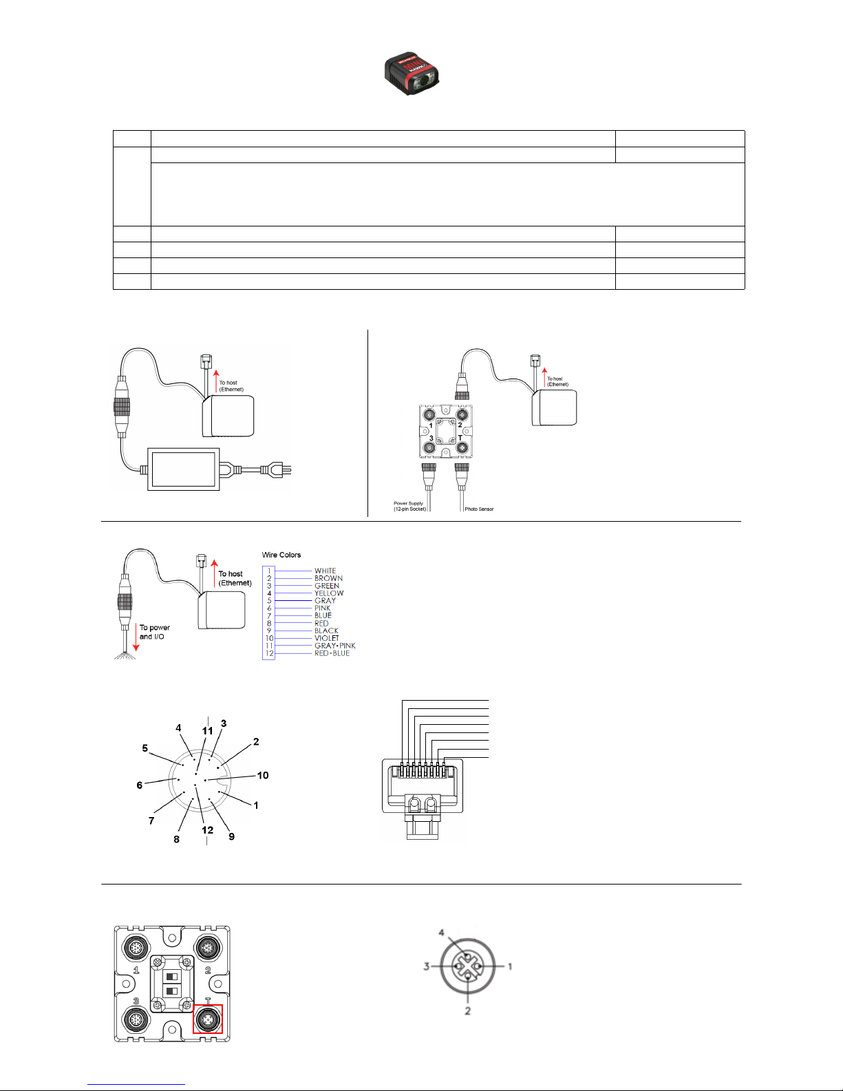
Ethernet Standalone with QX-1
Ethernet Standalone
Ethernet Standalone with Flying Leads
1
1
1
2
3
4
5
+10-28V
Trig ger
Ground
Trigger/New Master / Input 1 Common
Ground
Output 3
Output 1
Output 2
New Master
Default
Power
Input Common
Output Common
Host RxD
Trig ger
Host
TxD
QX-1 Interface
Device (Top View)
M12 12-pin Plug
Trigger Connector (T) 4-pin Socket
Connector T on the QX-1
Interface Device is the
trigger connector.
Connectors 1, 2, and 3
can be used to bus power
and data as required by
the application.
RJ45 Plug
P
T
1 TX (+)
8 NC
7 NC
6 RX (–)
5 NC
4 NC
3 RX (+)
2 TX (–)
Item Description Part Number
MINI Hawk Xi High Performance Imager FIS-6310-CLSOG
(C)ommunication: 1 (Ethernet)
1
(L)ens: 1 = Standard Density; 2 = High Density; 3 = Ultra High Density
(S)ensor: 0 = WVGA; 1 = SXGA
(O)ption: 0 = Standard; 1 = Custom
2 QX-1 Interface Device 98-000103-02
3 Power Supply, M12 12-pin Socket, 1.3 m (Screw-On) 97-000003-03
4 Photo Sensor, M12 4-pin Plug, NPN, Dark On, 2 m 99-000020-02
5 Cordset, M12 12-Pin Socket (Screw-on) to Flying Leads, 3M 61-000167-02
MINI Hawk Xi Configuration
MINI Hawk Xi Pin Assignments
Copyright ©2015 Microscan Systems, Inc. P/N 83-216310-04 Rev A
Page 2

MINI Hawk Xi Accessories
www.microscan.com
MINI Hawk Xi Accessories
Communication Devices and Cables
MS-Connect 210, Connectivity Box with Display FIS-0210-0001G
MS-Connect 210, Connectivity Box FIS-0210-0002G
MS-Connect 210, Connectivity Box with Display and Ethernet FIS-0210-0003G
MS-Connect 210, Connectivity Box with Ethernet FIS-0210-0004G
Relay Module, 120VAC, 3 Amp Output, Series 70, Type SM for MS-Connect 210 98-000013-04
Relay Module, 240VAC, 3 Amp Output, Series 70, Type SM for MS-Connect 210 98-000013-05
Relay Module, 24VDC, 3 Amp Output, Series 70, Type SM for MS-Connect 210 98-000013-06
Host Cable, MS-Connect 210 to Host, User-Stripped to 9-pin 61-000105-01
Host Cable, 9-pin to RJ12, 6’ (1,829 mm) 61-000108-01
Cordset, Common, M12 12 Pin, Socket (Screw-on) to M12 12 Pin Plug (Screw-on), 3 m 61-000148-02
Cordset, Host, Serial M12 12 pin Socket (Screw-on) to DB9 Socket, 1 m 61-000153-02
Cordset, Common, M12 12 Pin, Socket (Screw-on) to M12 12 Pin Plug (Screw-on), 1 m 61-000162-02
Cordset, Host, Serial, M12 12 pin Socket (Screw-on) to DB9 Socket, 3 m 61-000164-02
Other Accessories
Trigger Connector, 4-pin Plug (screw terminal and field-wireable) (for self-wiring) 20-610024-01
Object Detectors
Photo Sensor, Visible, NPN, Dark On 99-000017-01
Photo Sensor, Visible, NPN, Light On 99-000017-02
Photo Sensor, M12 4pin Plug, NPN, Dark Off, 2 m 99-000020-01
Mounting Options
Mounting Arm Kit: An adjustable mounting arm with ball and socket connections that allow the
arm to be positioned in almost any orientation.
Extension Joint Kit: Allows the mounting arm to be extended. Kit includes extension joint and
mounting arm.
Base Plate Kit: Plate for desktop presentation, 6” x 6” (152.4 mm x 152.4 mm). 98-000054-01
Through-Hole Mount Bracket: Allows the reader to be mounted to various surfaces. 98-000057-02
Side Mount Bracket: Allows the reader to be mounted at a 90º angle. 98-000060-01
Right-Angle Mirror Kit: Changes field of view direction by 90º. 98-000088-01
Diffuser Kit: Improves readability of direct part marks. 98-000098-01
Documentation
Microscan Tools Drive (Software, User Manuals, Quick Start Guides, Configuration Guides, links
to other documents on Microscan website)
Note: Additional accessories are available in the Microscan Product Pricing Catalog.
98-000048-01
98-000053-01 (4”)
98-000053-02 (3”)
37-000010-01
Copyright ©2015 Microscan Systems, Inc.
 Loading...