

Page 1

Visionscape® GigE Camera Guide
v4.1, November 2011
83-100029-02
Page 2

Copyright ©2011
Microscan Systems, Inc.
Tel: 425.226.5700 / 800.251.7711
Fax: 425.226.8250
ISO 9001 Certified
Issued by TüV USA
All rights reserved. The information contained herein is proprietary and is provided solely for the purpose of
allowing customers to operate and/or service Microscan manufactured equipment and is not to be released,
reproduced, or used for any other purpose without written permission of Microscan.
Throughout this manual, trademarked names might be used. We state herein that we are using the names to the
benefit of the trademark owner, with no intention of infringement.
Disclaimer
The information and specifications described in this manual are subject to change without notice.
Latest Manual Version
For the latest version of this manual, see the Download Center on our web site at:
www.microscan.com.
Technical Support
For technical support, e-mail: helpdesk@microscan.com.
Warranty and Terms of Sale
For Standard Warranty information, see: www.microscan.com/warranty.
Microscan Systems, Inc.
Renton Headquarters
425.226.5700 / 800.251.7711
Nashua Office
603.598.8400
Microscan Europe
011 31 172 423360
Microscan Asia Pacific
65 6846 1214
Page 3

Contents
PREFACE Welcome! v
Purpose of This Manual v
Manual Conventions v
CHAPTER 1 Introduction 1-1
Product Summary 1-2
Features and Benefits 1-3
Applications 1-4
Package Contents 1-4
Visionscape
CHAPTER 2 System Components 2-1
Basic Components 2-1
Visionscape
Front Panel 2-3
Rear Panel 2-3
Mode/Status LEDs 2-4
Important Label Information 2-4
Mounting and Wiring the Visionscape
Field I/O Wiring Examples 2-7
Input Opto Wiring 2-7
Output Opto Wiring 2-9
External Strobe and Sensor 2-11
Power Requirements 2-11
®
GigE Camera Models 1-5
®
GigE Camera 2-2
®
GigE Camera 2-5
v4.1, November 2011 Visionscape GigE Camera Guide iii
Page 4

Contents
Power Supply Wiring 2-11
Configuring Your Network Adapter for GigE Visionscape 2-23
How to Modify the dm.config File to Change Camera and System
Assignments 2-37
Visionscape GigE Network Configuration 2-62
CHAPTER 3 Optics 3-1
Optics 3-2
APPENDIX A Connector Pinouts A-1
Visionscape
®
GigE Camera Connectors A-2
Power Connector A-2
Strobe and Trigger Connector A-3
Gigabit Ethernet Connector A-4
APPENDIX B Cable Specifications B-1
98-000129-01 Visionscape
98-000126-01 Visionscape® GigE Camera Strobe/Trigger M8-4 to Pigtail 5M B-3
98-000133-01 and 98-000134-01 Cat 6 Ethernet with Jack Screws to RJ45
High Flex B-4
®
GigE Camera Power M8-3 to Pigtail 5M B-2
APPENDIX C Specifications C-1
Dimensions C-4
Spectral Sensitivity C-7
iv Visionscape GigE Camera Guide v4.1, November 2011
Page 5

Preface
PREFACE Welcome!
Purpose of This Manual
This manual contains detailed information about the Visionscape® GigE
Camera.
Manual Conventions
The following typographical conventions are used throughout this manual.
• Items emphasizing important information are bolded.
• Menu selections, menu items and entries in screen images are
indicated as: Run (triggered), Modify..., etc.
v4.1, November 2011 Visionscape GigE Camera Guide v
Page 6

Preface
vi Visionscape GigE Camera Guide v4.1, November 2011
Page 7
1
CHAPTER 1 Introduction
1
Introduction
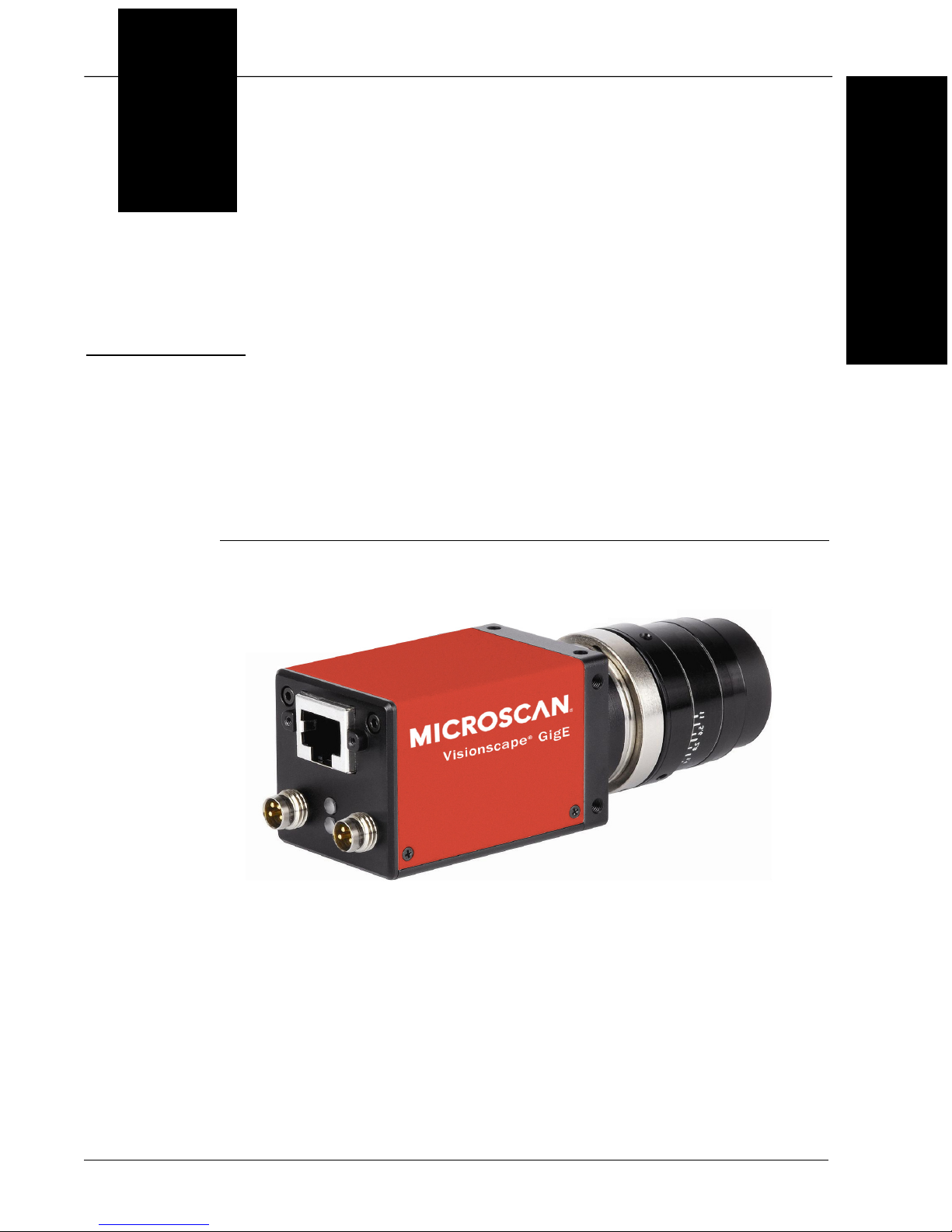
FIGURE 1–1. Visionscape
®
GigE Camera
v4.1, November 2011 Visionscape GigE Camera Guide 1-1
Page 8

Chapter 1 Introduction
Product Summary
Microscan GigE cameras are a range of cameras that are designed to
perform the imaging and image transmission functions in a Visionscape
PC based machine vision system that uses the GigE Vision standard for
image transfer.
The combination of Microscan GigE cameras and the Visionscape
software allows the development of cost-effective, easily-deployed
solutions for quality control, guidance or part identification.
Visionscape software, which offers an extensive array of built-in vision
processing tools, including Data Matrix and bar code reading, optical
character recognition (OCR), image processing, image analysis, and
feature extraction, flaw detection, object location, calibrated dimensional
measurements, and various custom processing options. Developed and
perfected on prior generations of machine vision systems, these tools
have already been successfully applied in thousands of production
installations worldwide.
Setup of a new vision application employing Microscan GigE camers is
performed on a host PC using the same powerful graphical application
environment as the rest of the Visionscape line. The patented
Visionscape step program architecture allows transfer of a vision
application program between systems using GigE Cameras and those
using the VS-1 Smart Camera, leveraging the end-user’s investment in
application development and training.
The Microscan GigE camera range includes cameras with resolutions
that range from VGA to QXGA. The range includes cameras with CMOS
and CCD sensors as well as cameras with color output capability.
All Microscan GigE cameras support C-mount lenses. The significant
features of the cameras physical configuration are as follows:
• Square camera body cross section with mounting points on all four
sides allows flexible mounting
• All cameras are supplied with an attached mounting bracket with ¼ 20 thread
• Network connection with jack screws for positive cable retention
• Strobe/Trigger connection for direct trigger and strobe output
1-2 Visionscape GigE Camera Guide v4.1, November 2011
Page 9

• Power connection (8-to-30VDC)
• Strobe/Trigger and Power connections are standard M8 with positive
retention
Features and Benefits
Microscan GigE Vision:
• Low cost solutions for PC based machine vision
• High usable bandwidth for imaging
• Multiple camera support
• Use of low cost commodity components for image transfer
Features and Benefits
1
Introduction
• Support for built in I/O at the PC
• Power over Ethernet option for VGA camera
Applications
• Part presence/absence
• Assembly verification
• Inspection
• Gauging
• Part location/orientation detection
• Alignment/guidance
• Automatic ID (Data Matrix, bar code, OCR)
v4.1, November 2011 Visionscape GigE Camera Guide 1-3
Page 10

Chapter 1 Introduction
Package Contents
Before you install Visionscape software and connect your Visionscape
GigE Camera, please take a moment to confirm that the following items
are available:
• Visionscape GigE Camera — Your package contains one of the
available GigE Camera models listed on the next page (see
Table 1–1)
• Visionscape Software Installation CD
• Visionscape 4.1 License Key
• Required accessories such as a power supply or power cable and
CAT6 network cable
Visionscape® GigE Camera Models
Table 1–1 lists and describes the Visionscape GigE Camera models,
including acquisition modes and resolutions.
TABLE 1–1. Visionscape
Part Number
98-000113-01 CMGC03 VGA Mono CMOS 752 x 480 1/3” 60
98-000114-01 CMGC03C VGA Color CMOS 748 x 476 1/3” 60
98-000115-01 CMG03 VGA Mono CCD 656 x 494 1/3” 90
98-000116-01 CMG03C VGA Color CCD 656 x 490 1/3” 90
98-000141-01 CMG04 VGA Mono CCD – 1/2”
98-000117-01 CMG08 XGA Mono CCD 1032 x 776 1/3” 28
98-000118-01 CMG13 SXGA Mono CCD 1392 x 1040 1/2” 20
98-000119-01 CMG20 UXGA Mono CCD 1624 x 1236 1/1.8” 16
98-000120-01 CMG50 QSXGA Mono CCD 2448 x 2050 2/3” 15
98-000121-01 CMG03-P VGA Mono CCD POE 656 x 494 1/3” 90
Visionscape GigE
Camera Model
Sensor
®
GigE Camera Models and Resolutions
Resolution
656 x 494 1/2” 57
Sensor
Size
FPS
1-4 Visionscape GigE Camera Guide v4.1, November 2011
Page 11

2
CHAPTER 2 System Components
2
System Components
This section contains information about system components as well as
information to help you connect the Visionscape
information describes connectors, adapters, cables, pinouts, signals, and
network configuration.
Note: There are no user-serviceable parts inside.
Basic Components
Table 2-1 lists the Visionscape® GigE Camera hardware components.
Note: CMOS Visionscape GigE cameras (CMGC03 and CMGC03c – 98000113-01 and 98-000114-01) do not report trigger overrun (too-fast
trigger) conditions. These cameras should not be specified for high trigger
rate applications where overruns may occur.
TABLE 2–1. Visionscape
®
GigE Camera. Specific
®
GigE Camera Hardware Components
Part Number Description
Cameras
98-000113-01 Visionscape
98-000114-01 Visionscape
98-000115-01 Visionscape
v4.1, November 2011 Visionscape GigE Camera Guide 2-1
®
GigE Camera – VGA Mono CMOS
®
GigE Camera – VGA Color CMOS
®
GigE Camera – VGA Mono CCD
Page 12

Chapter 2 System Components
TABLE 2–1. Visionscape
®
GigE Camera Hardware Components (Continued)
Part Number Description
98-000116-01 Visionscape® GigE Camera – VGA Color CCD
98-000141-01 Visionscape
98-000117-01 Visionscape
98-000118-01 Visionscape
98-000119-01 Visionscape
98-000120-01 Visionscape
98-000121-01 Visionscape
®
GigE Camera – VGA Mono CCD 1/2” Sensor
®
GigE Camera – XGA Mono CCD
®
GigE Camera – XSGA Mono CCD
®
GigE Camera – UXGA Mono CCD
®
GigE Camera – QSXGA Mono CCD
®
GigE Camera – VGA Mono CCD POE
Starter/Evaluation Kit
98-000139-01 Visionscape
®
GigE Starter/Evaluation Kit
Power Supplies
98-000138-01 Visionscape
®
GigE Camera Power Supply
Cables
®
98-000126-01 Visionscape
98-000129-01 Visionscape
GigE Camera Strobe/Trigger M8-4 to Pigtail 5M
®
GigE Camera Power M8-3 to Pigtail 5M
98-000133-01 Cat6 Ethernet with Jackscrews to RJ45 High Flex 2M
98-000134-01 Cat6 Ethernet with Jackscrews to RJ45 High Flex 5M
I/O Boards
98-000130-01 PCIe DIO Card 16 In 16 Out Isolated with Cable and Terminal
98-000142-01 PCIe DIO Card 16 In 16 Out Isolated with Cable and Terminal (PNP) Current Sourcing
GigE Port Adapters
98-000124 GigE 4 Port Switch – POE Injection
98-000125 GigE Power Injector – 2 Inputs and 2 Outputs
98-000131 GigE 5 Port Switch
98-000140 Single Port GigE Network PCIe Interface Card
98-000132 Dual Port GigE Network PCIe Interface Card
GigE Licenses
GMV-VGL0-0DD0 Basic Visionscape
GMV-VGL0-1DD0 Basic Visionscape
®
GigE License
®
GigE License with Intellifind
2-2 Visionscape GigE Camera Guide v4.1, November 2011
Page 13
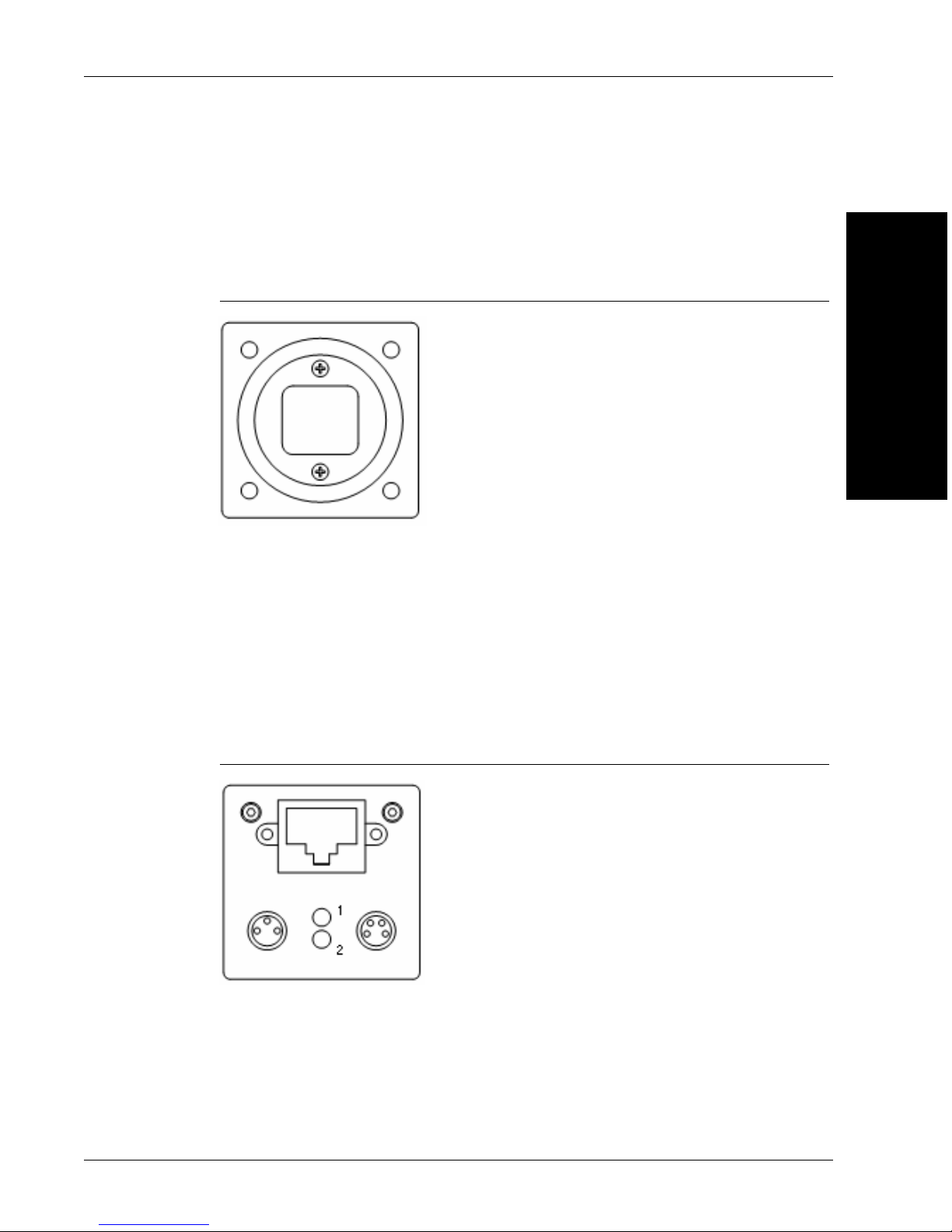
Front Panel
Figure 2–1 shows the front C-Mount Lens threads for the Visionscape®
GigE Camera.
FIGURE 2–1. Front Panel
Basic Components
2
System Components
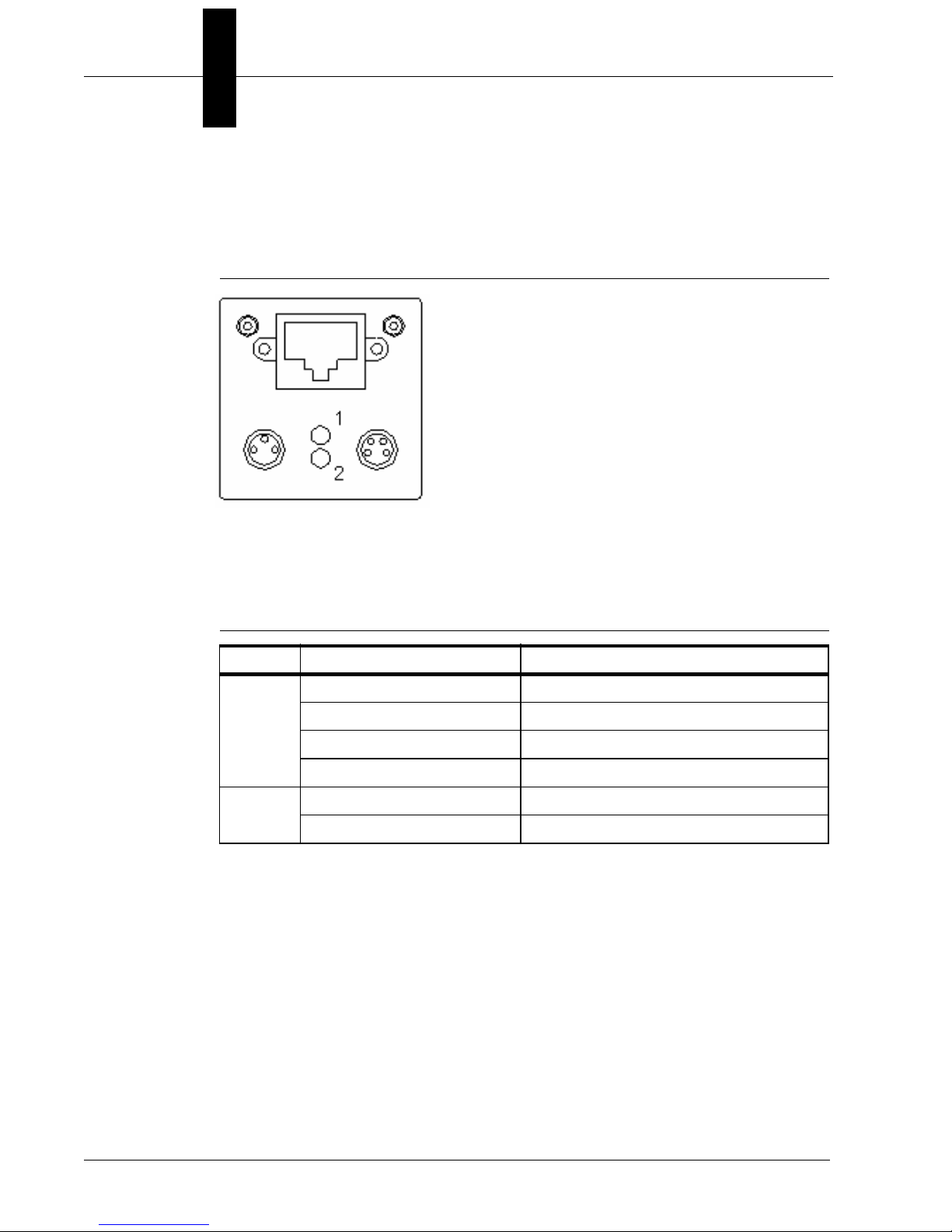
Rear Panel
Figure 2–2 shows the layout of the rear panel which contains the RJ45
socket for the Gigabit Ethernet network connection, an M8-3 connector
for power and an M8-4 connector for trigger and strobe signals.
FIGURE 2–2. Rear Panel
v4.1, November 2011 Visionscape GigE Camera Guide 2-3
Page 14
Chapter 2 System Components
Mode/Status LEDs
Figure 2–3 shows the mode and status LEDs.
FIGURE 2–3. Mode/Status LEDs
Table 2-2 describes the mode and status LEDs.
TABLE 2–2. Mode/Status LEDs
LED Color Function
Green Power On
1
2
Yellow Readout Active
Green Link Active
Green Flashing Receiving
Yellow Transmitting
Yellow/Red Flashing Receiving and Transmitting
Important Label Information
Each Visionscape® GigE Camera has its own label, which contains
important information about that camera.
• P/N – The Microscan part number of your Visionscape GigE Camera.
• S/N — The serial number of your Visionscape GigE Camera.
• MAC — The MAC address of your Visionscape GigE Camera.
• Type — The model type of your Visionscape GigE Camera.
2-4 Visionscape GigE Camera Guide v4.1, November 2011
Page 15

Basic Components
Mounting and Wiring the Visionscape® GigE Camera
• Mount the camera securely in its camera stand (not supplied).
• Make sure the camera is mounted at the correct distance for the
optics you’ve purchased.
2
• Connect the Ethernet cable and the power cable to the Visionscape
GigE Camera. Connect the Visionscape
power supply or to the Visionscape GigE power supply.
®
GigE Camera to a 24V
Mounting Using Front Block
Note: Do not insulate the mounting block. The mounting block of the
Visionscape
metal-to-metal contact is required for effective cooling. Refer to
Appendix C, “Specifications", for mounting block dimensions.
You can mount the Visionscape
located on the front, top, bottom, and each side of the front block, as
shown in Figure 2–4.
FIGURE 2–4. Locations for Mounting Using Front Block
®
GigE Camera is part of the heat dissipation system, and
®
GigE Camera using the M3 holes
®
System Components
v4.1, November 2011 Visionscape GigE Camera Guide 2-5
Page 16
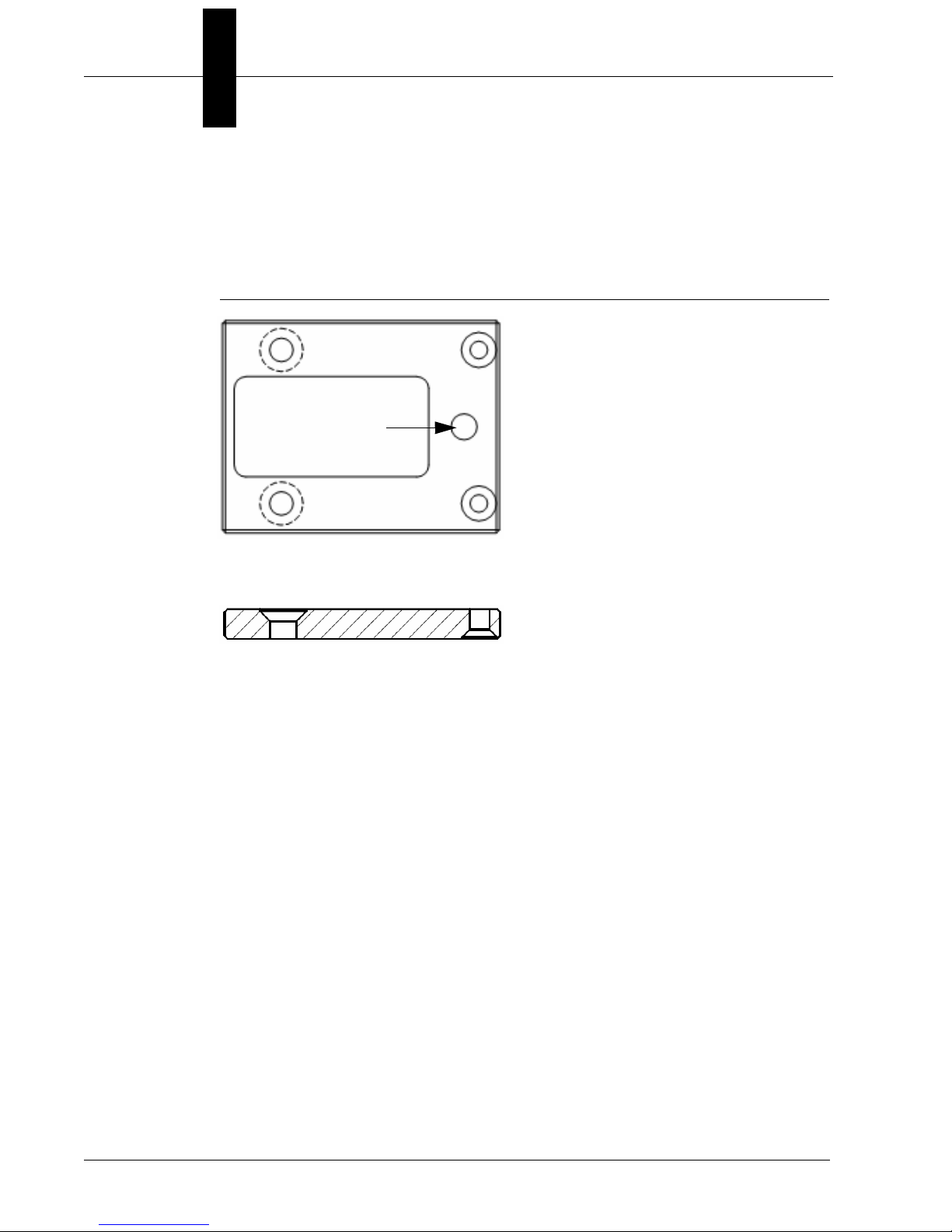
Chapter 2 System Components
¼-20 threaded
mounting hole
6 mm from edge
Top View
Side View
Length: 47 mm
Width: 36 mm
Mounting Using Base Mounting Plate
You can mount the Visionscape® GigE Camera using the base mounting
plate that is supplied with the camera (see Figure 2–5).
FIGURE 2–5. Base Mounting Plate
2-6 Visionscape GigE Camera Guide v4.1, November 2011
Page 17

Visionscape Digital I/O (DIO)
Visionscape Digital I/O (DIO)
Visionscape 4.1 supports interfaces to discrete digital signals from three
types of hardware. These are:
• VS-1 Smart Cameras
• Visionscape GigE cameras
• Visionscape PCIe Digital I/O boards
The DIO capability of the VS-1 Smart Camera is described in full in the
VS-1 Smart Camera Guide. That of the GigE cameras and the PCIe
boards is described below.
Visionscape GigE Camera I/O
Built-In Trigger Input 2
The Visionscape GigE cameras incorporate an input for a trigger signal
that can be used to initiate image acquisition.
2
System Components
Figure 2–6 shows the input opto wiring (TrigIN) for isolated NPN and PNP
sources such as photo-eyes or PLC outputs.
FIGURE 2–6. Input Opto Wiring (TrigIN) for NPN and PNP Sources
v4.1, November 2011 Visionscape GigE Camera Guide 2-7
Page 18
Chapter 2 System Components
Trigger Signal Requirements:
Logic Low: 0 to 4.5 Vdc Logic High: 11 to 30 Vdc
Current Input: 20ma (typical) Trigger Delay: 3usec (Minimum) Trigger
Pulse Width: 2usec (Minimum)
DebounceHigh: 0 to 5 usecs (User-Defined)
DebounceLow: 0 to 5 usecs (User-Defined)
Built-In Strobe Output
The Visionscape GigE cameras incorporate an output for a strobe signal
that is coordinated with image acquisition.
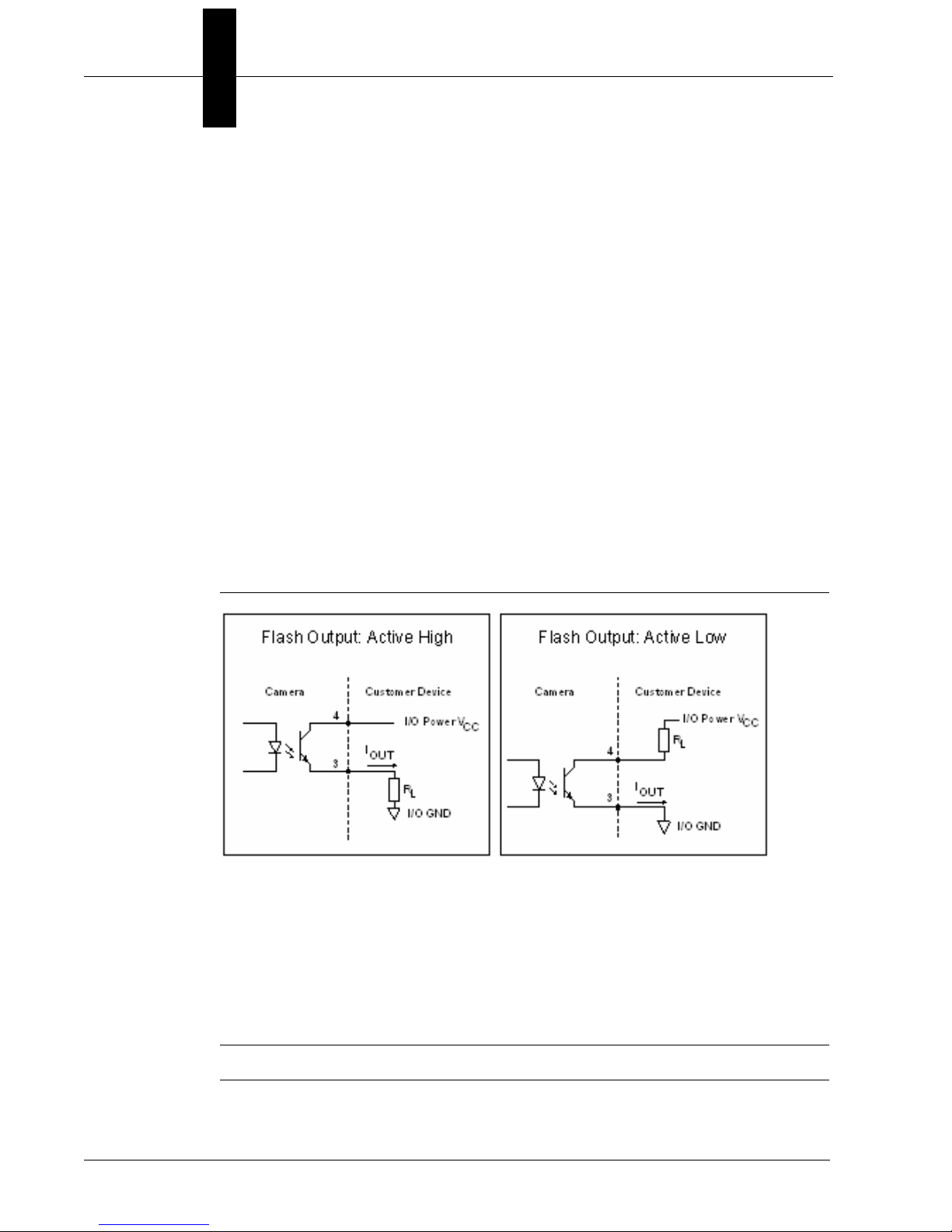
Figure 2–7 shows the output opto wiring (Strobe ) for isolated outputs.
FIGURE 2–7. Output Opto Wiring (Flash) for Isolated Inputs
Flash Output Signal Response:
Logic Low: 0 to 4.5 Vdc
Logic High: 5 to 30 Vdc. (24Vdc @ 16ma recommended)
Flash Delay: 2usec (typical)
Note: Flash Off Time: ~ 40?sec.
2-8 Visionscape GigE Camera Guide v4.1, November 2011
Page 19
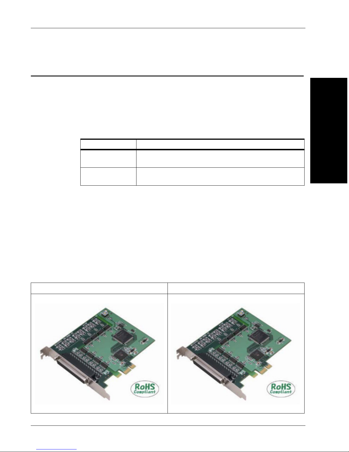
Visionscape PCIe Digital I/O Boards
Visionscape PCIe Digital I/O Boards
Extended discrete digital I/O is provided for GigE/PC based systems by
two PCIe (PCI Express) add-in boards. These boards both provide 16
channels in and 16 channels out of optically isolated I/O at 24 volts
nominal signal level.
The two boards are:
Part Number Description
98-000130-01 DIO Kit, Current Sinking Configuration, VS GigE I/O (NPN)
(L)
98-000142-01 DIO Kit, Current Source Configuration, VS GigE I/O (PNP)
(RL)
The DIO board should be specified according to the requirement of the
installation concerning the electrical interface to equipment such as PLCs
or sensors.
These boards are PCI Express bus-compliant interface board used to
provide a digital signal I/O function on a PC. They product can input and
output digital signals at 12 - 24VDC.They provide 16 opto-coupler isolated
inputs and 16 opto-coupler isolated outputs with digital filter function to
prevent wrong recognition of input signals and output transistor protection
circuit for surge voltage protection and over-current protection).
2
System Components
98-000142-01 (Sourcing) 98-000130-01 (Sinking)
v4.1, November 2011 Visionscape GigE Camera Guide 2-9
Page 20
Chapter 2 System Components
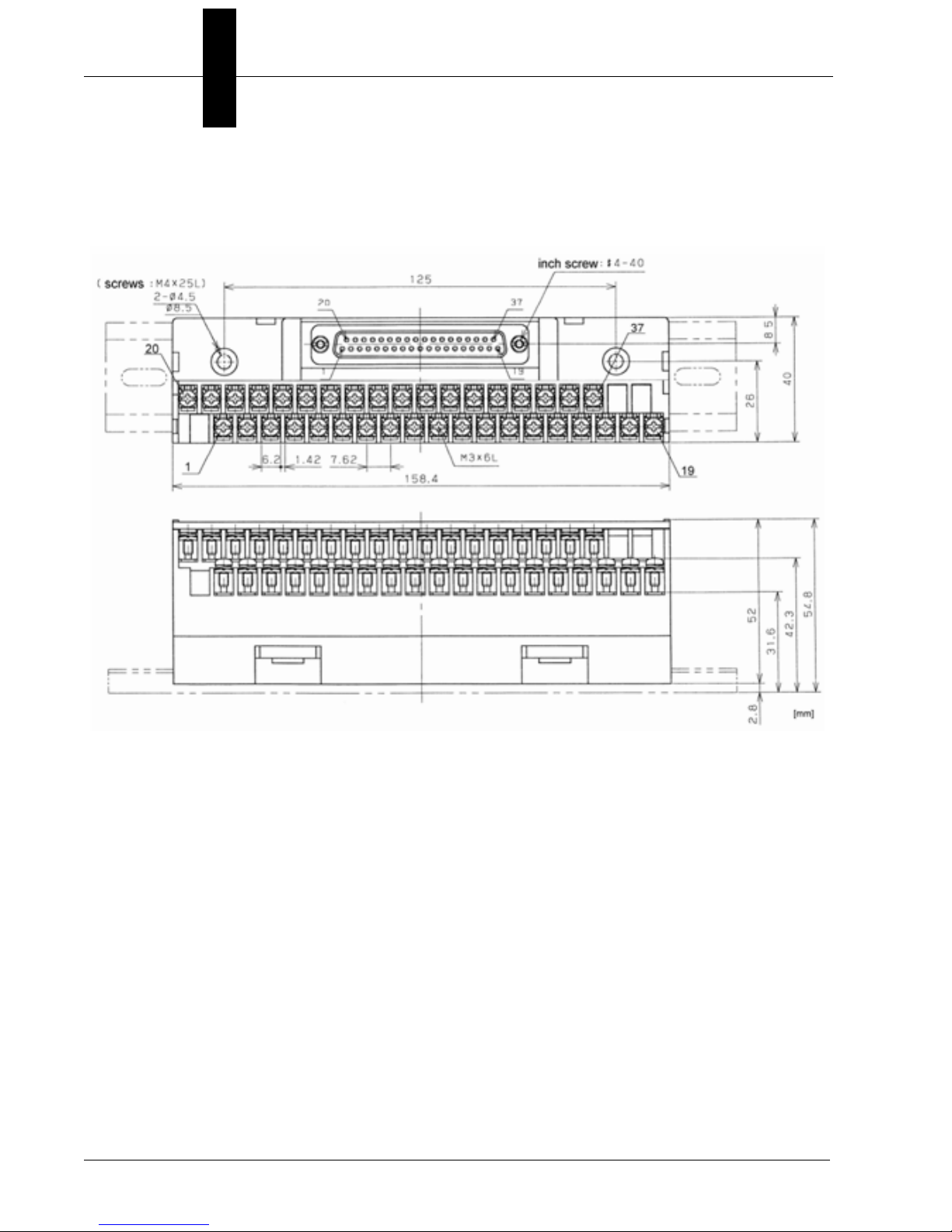
Both DIO kits are supplied with a 1.5m cable (Shielded Cable with two 37-pin
D-Sub Connectors) for connection to a 32 DIN rail mount terminal strip,
the dimensions of which are shown below.
2-10 Visionscape GigE Camera Guide v4.1, November 2011
Page 21

Visionscape PCIe Digital I/O Boards
The critical specification items for the two boards are listed below:
98-000142-01
(Sourcing)
Input Format Opto-isolated input
(Compatible with current
source output) (Negative
logic *1)
Number of Input Signal
Channels
Input Resistance 4.7k?
Input ON current 2.0mA or more
Input OFF Current 0.16mA or less
Response Time Within 200?sec
Output Format Opto-isolated output
Number of Output Signal
Channels
16 channels (all available for interrupts)(One
common)
(Current source type)
(Negative logic *1)
16 channels (One common)
98-000130-01
(Sinking)
Opto-coupler isolated
input (Compatible with
current sink output)
(Negative logic *1)
Opto-coupler isolated
open collector output
(current sink type)
(Negative logic *1)
2
System Components
Output Voltage 35 VDC (Max.)
Output Current 100mA (per channel) (Max.)
Residual Voltage with
Output On
Surge Protector Zener diode RD47FM (NEC) or equivalent
Response Time Within 200?sec
External Circuit Power
Supply
Power Consumption 3.3VDC 350mA (Max.)
Operating Conditions 0 - 50°C, 10 - 90%RH (No condensation)
Bus Specification PCI Express Base Specification Rev. 1.0a x1
Dimension (mm) 121.69(L) x 110.18(H)
Connector 37 pin D-SUB connector (female) DCLC-J37SAF-
Weight 90g 130g
0.5V or less (Output current ? 50mA), 1.0V or less
(Output current ? 100mA)
12 - 24VDC (±10%)
20L9E (JAE) or equivalent
v4.1, November 2011 Visionscape GigE Camera Guide 2-11
Page 22
Chapter 2 System Components
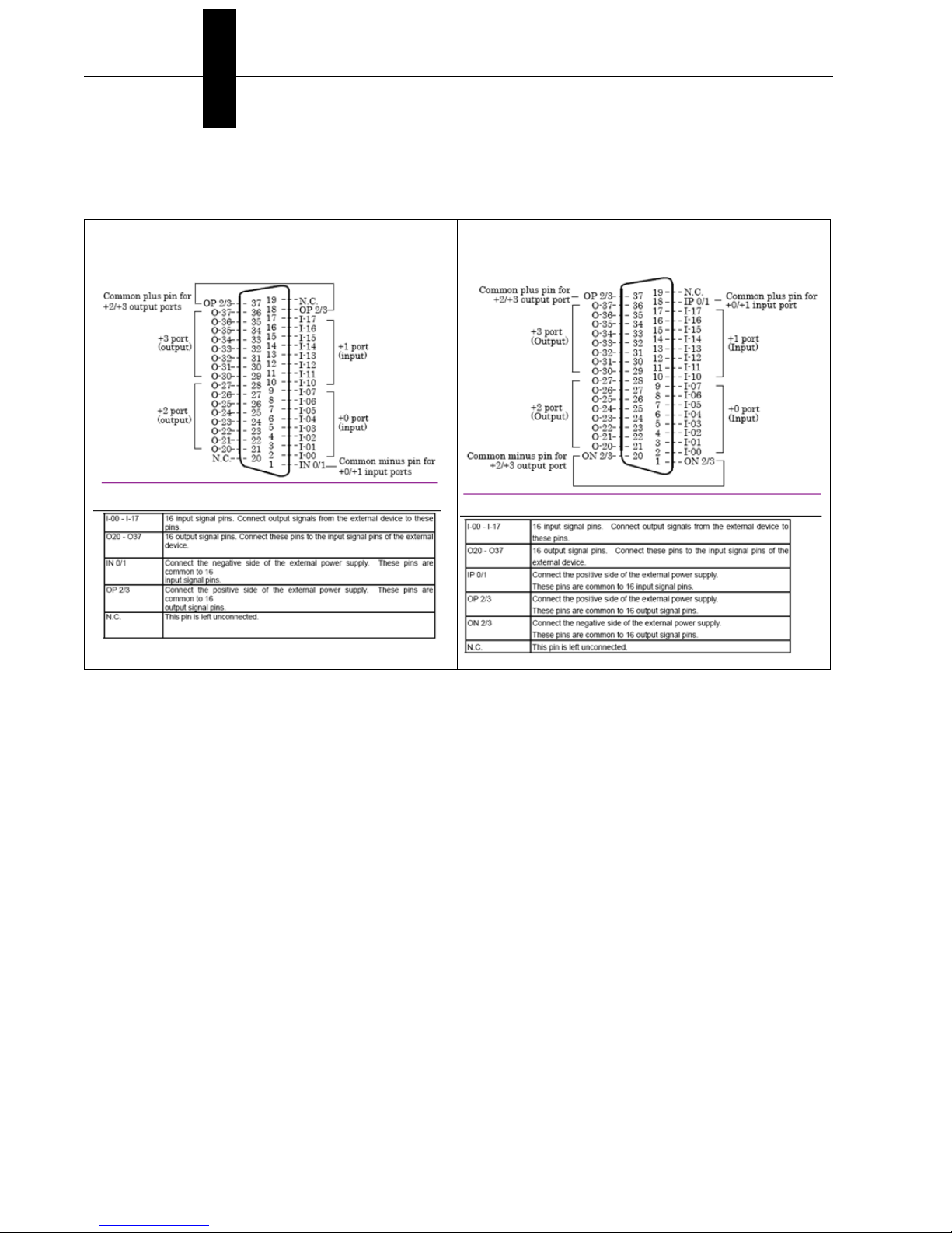
Connector Pin Assignments are as shown below for each board.
98-000142-01 (Sourcing) 98-000130-01 (Sinking)
Using Input Points for Triggering Acquisition
Hardware input points located on the DIO board may be specified in the
Visionscape Acquire Step to trigger acquisition. Acquisition can be
specified on either the leading edge or trailing edge of a pulse. If the
Visionscape PCIe IO boards are used in this manner the following
procedure must be observed.
1. If leading (low-to-high, rising) edge triggering is specified the trigger
signal must be wired to one of the lower 8 input points (I-00 to I07) in
the diagram above – IN0 to IN7 in Visionscape
2. If trailing (high-to-low, falling) edge triggering is specified the trigger
signal must be wired to one of the upper 8 input points (I-10 to I-17) in
the diagram above – IN8 to IN15 in Visionscape.
This constraint is only applicable to Input points used as triggers in the
Acquire or the Digital Input Step. The Digital Input Step will report the
state of all 16 inputs at the time that it is called if no Data Valid signal is
assigned.
2-12 Visionscape GigE Camera Guide v4.1, November 2011
Page 23

Digital I/O Input Response Time
The response time of Visionscape to a change of an input signal is a
combination of the hardware and software response times. The hardware
response time for all inputs is within 200?s from voltage change on an
external pin to go through the optical isolation and be received by the PC.
Note that the optical isolation will invert the signals. For example, a highto-low voltage transition will be seen by the software as a logical low-tohigh transition.
The software response time varies by input pin and direction. Inputs 0-7
are tuned for a faster response on logical low-to-high transitions.
Conversely, inputs 8-15 are tuned for faster response on logical high-tolow transitions. Trigger signals should be connected to pins in which the
trigger direction matches the tuned response direction of the pin. The
software response for logical low-to-high transitions on pins 0-7 (or highto-low transitions on pins 8-15) is approximately 100?s. The software
response time for the opposite transition of a logical high-to-low on pins 07 (or logical low-to-high on pins 8-15) is 10ms.
Visionscape PCIe Digital I/O Boards
2
System Components
Cycles can be less than 10ms without missing trigger events. 10ms
represents the longest delay for being notified of a transition. This is
relevant for IO Display Windows as the minimum update speed of the
visual indicators. It would also affect input triggers if they are set to use
the opposite edge from the direction it is tuned. For example, when using
pin 0 as a trigger on a logical high-to-low signal when that pin is tuned for
a fast logical low-to-high response time. In this case the trigger may occur
up to 10ms after the change of the signal state on the input pin.
The IO State datum of the Snapshot step reads the logical state of the
input pins at the time of an image acquisition and is not subject to the
10ms response time limitation.
If multiple inputs change states simultaneously, the processing of those
transitions is done sequentially. Therefore, the maximum response time to
a trigger is subject to the number of asynchronous triggers that may occur
simultaneously. The maximum response time to a trigger can be
approximated by the number of possible simultaneous transitions x 100?s
plus 200?s for the hardware response time. For example, if two inputs
change state simultaneously, the two transitions would be processed
v4.1, November 2011 Visionscape GigE Camera Guide 2-13
Page 24
Chapter 2 System Components
within 400?s this is calculated by taking the 200?s hardware response for
inputs + 200?s software response of the two changes at 100?s each.
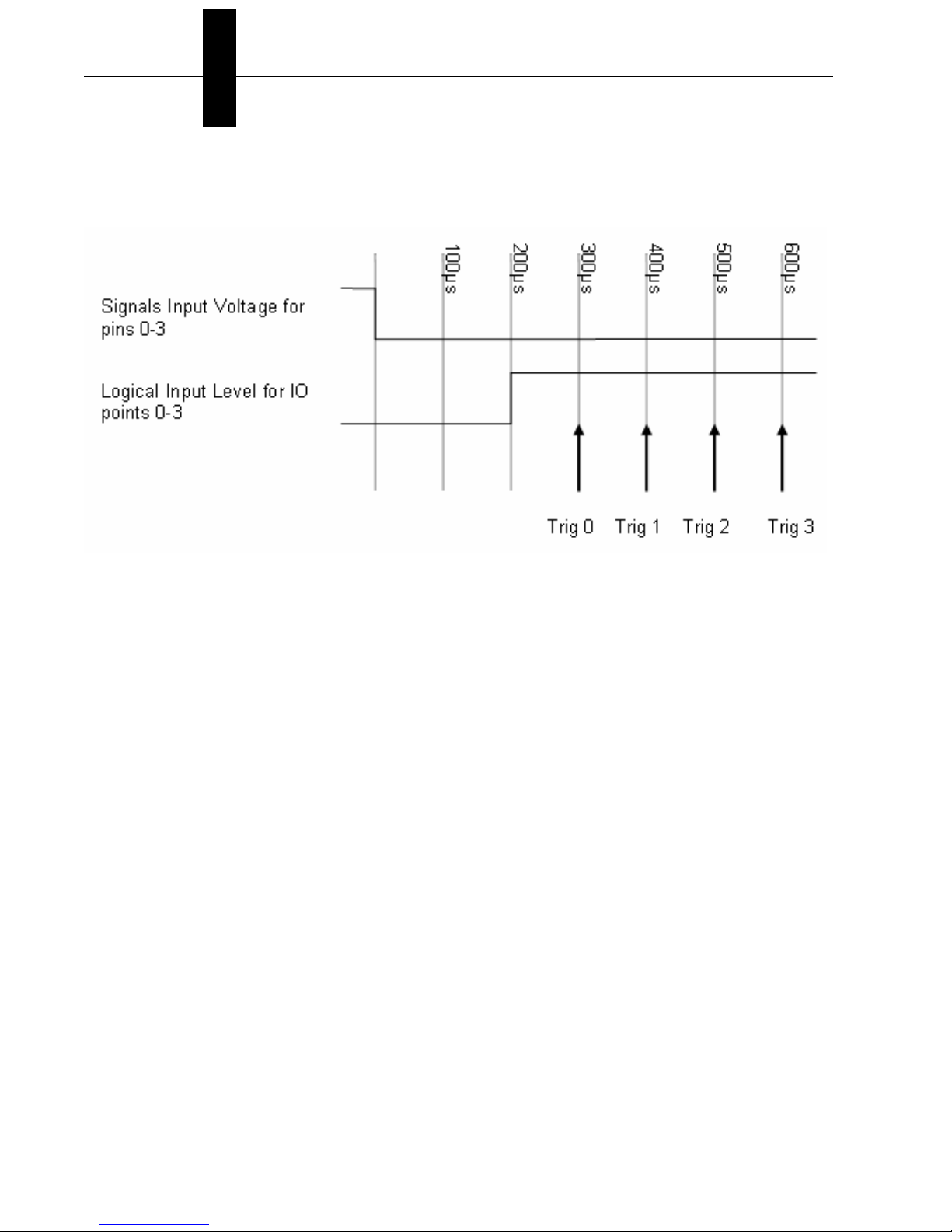
The above diagram represents the scenario of 4 input triggers
transitioning simultaneously. After the voltage goes from high to low on
the pins 0-3, it can take up to 200?s for the computer to register the level
of inputs 0-3 and be read as logic highs. Once the logical low-to-high
transition has occurred, each trigger response can take 100?s to process.
In the case of 4 simultaneous transitions, it can take up to 600?s for the
last trigger response. If transitions occur simultaneously, the transitions
will be processed in an indeterminate order.
2-14 Visionscape GigE Camera Guide v4.1, November 2011
Page 25
Visionscape PCIe Digital I/O Boards
Field Wiring for Current Sourcing Configurations
Input Wiring
The input circuits of interface blocks of the current sourcing DIO board is
illustrated in the image below. The signal inputs are isolated by optocouplers (ready to accept current sinking output signals). The board
therefore requires an external power supply to drive the inputs. The
power requirement for each input pin approximates to 5.1mA at 24VDC
(or 2.6mA at 12VDC).
2
System Components
v4.1, November 2011 Visionscape GigE Camera Guide 2-15
Page 26

Chapter 2 System Components
Digital I/O Trigger Wiring
As noted above, the event notification on input lines is mono-directional.
Inputs 0 to 7 can be used as a low-to-high trigger only, while inputs 8 to 15
can be used as a high-to-low trigger. In cases where trigger events are
needed from both edges of a signal, the signal needs to be simultaneously
wired to a low-to-high sensitive input pin and a high-to-low sensitive pin
as shown in the above diagram. All 16 inputs are available for general
purpose reading when not used for triggering events.
2-16 Visionscape GigE Camera Guide v4.1, November 2011
Page 27
Connecting a Switch Input
Output Wiring
Visionscape PCIe Digital I/O Boards
2
Connect the output signals to a current-driven controlled device such as a
relay or LED. The connection requires an external power supply to feed
currents. The board controls turning on/off the current-driven controlled
device using a digital value.
System Components
v4.1, November 2011 Visionscape GigE Camera Guide 2-17
Page 28
Chapter 2 System Components
The output circuits of interface blocks of the DIO-1616RL-PE are
illustrated above. The signal output section is an opto-coupler isolated
output (current source type). Driving the output section requires an
external power supply. The rated output current per channel is 100mA at
maximum. A zener diode is connected to the output transistor for
protection from surge voltages. A PolySwitch-based over-current
protector is provided for every eight output transistors. When the overcurrent protector works, the output section of the board is temporarily
disabled. If this is the case, turn of the power to the PC and the external
power supply and wait for a few minutes, then turn them on.
Important: When the PC is turned on, all outputs are reset to OFF.
Example of connection to an LED:
2-18 Visionscape GigE Camera Guide v4.1, November 2011
Page 29

Visionscape PCIe Digital I/O Boards
Field Wiring for Current Sinking Configurations
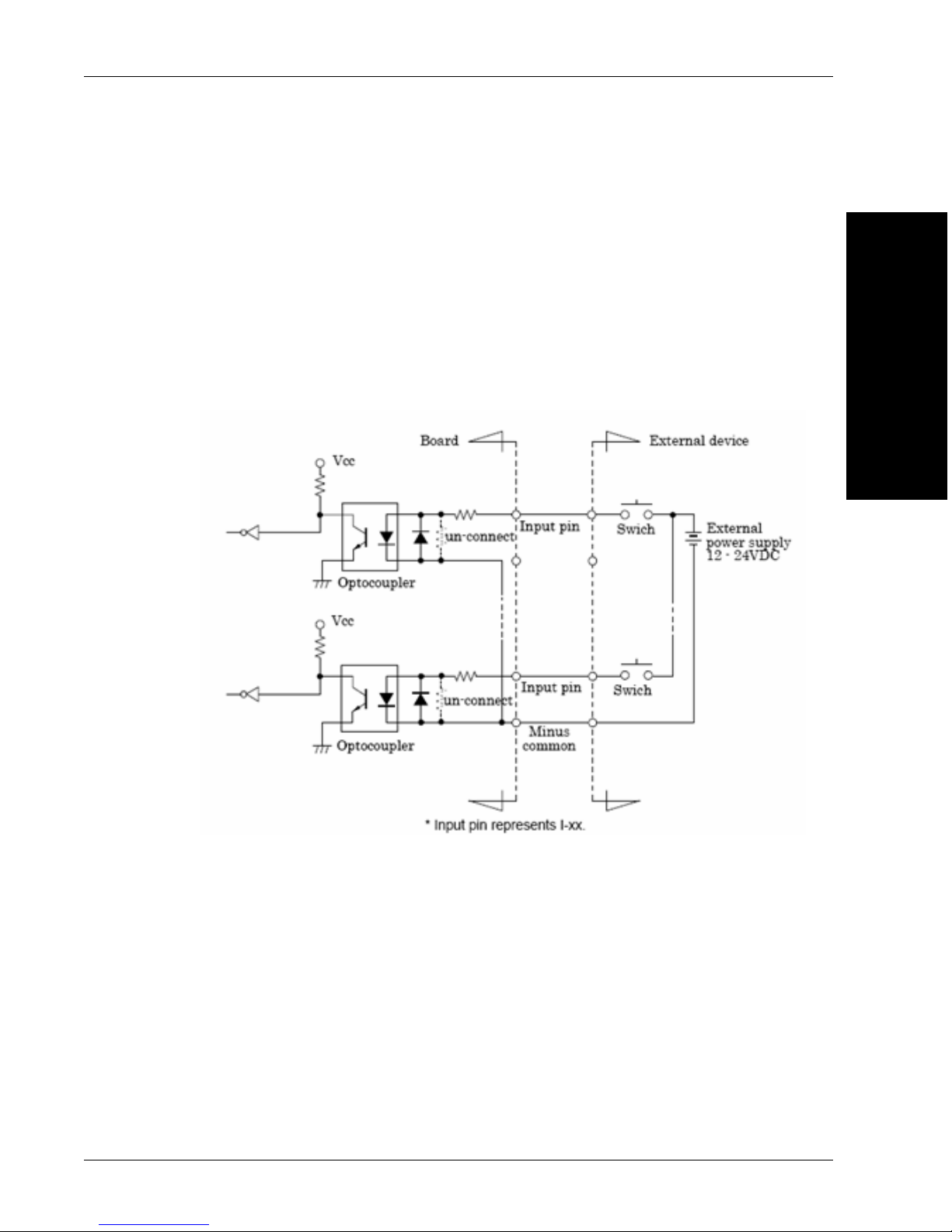
Input Wiring
Connect the input signals to a device which can be current-driven, such
as a switch or transistor output device. The connection requires an
external power supply to feed current. The board inputs the ON/OFF state
of the current-driven device as a digital value.
2
System Components
The input circuits of interface blocks of this product is illustrated in the
image above. The signal inputs are isolated by opto-couplers (ready to
accept current sinking output signals). The board therefore requires an
external power supply to drive the inputs. The power requirement for each
input pin is about 5.1mA at 24VD (about 2.6mA at 12VDC).
v4.1, November 2011 Visionscape GigE Camera Guide 2-19
Page 30

Chapter 2 System Components
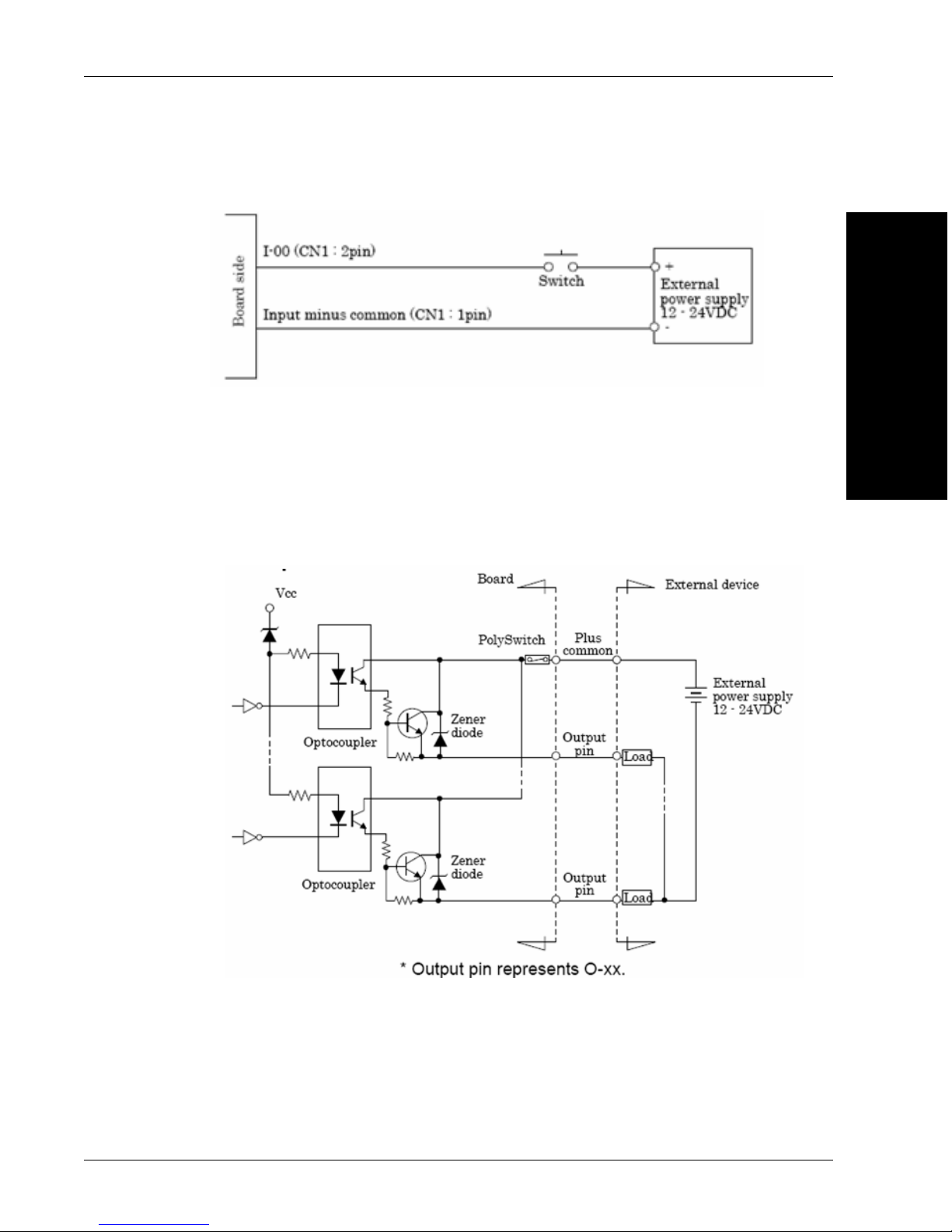
Connecting a Switch
Output Wiring
Connect the output signals to a current-driven controlled device such as a
relay or LED. The connection requires an external power supply to feed
current. The board controls turning on/off the current-driven controlled
device using a digital value.
Output Circuit
2-20 Visionscape GigE Camera Guide v4.1, November 2011
Page 31

Visionscape PCIe Digital I/O Boards
The output circuits of interface blocks of this product is illustrated in the
image above. The signal output section is an opto-coupler isolated, opencollector output (current sink type). Driving the output section requires an
external power supply. The rated output current per channel is 100mA at
maximum. The output section can also be connected to a TTL level input
as it uses a low-saturated transistor for output. The residual voltage (lowlevel voltage) between the collector and emitter with the output on is 0.5V
or less at an output current within 50mA or at most 1.0V at an output
current within 100mA. A zener diode is connected to the output transistor
for protection from surge voltages. A PolySwitch-based overcurrent
protector is provided for every 8 output transistors. When the overcurrent
protector works, the output section of the board is temporarily disabled. If
this is the case, turn of the power to the PC and the external power supply
and wait for a few minutes, then turn them on back.
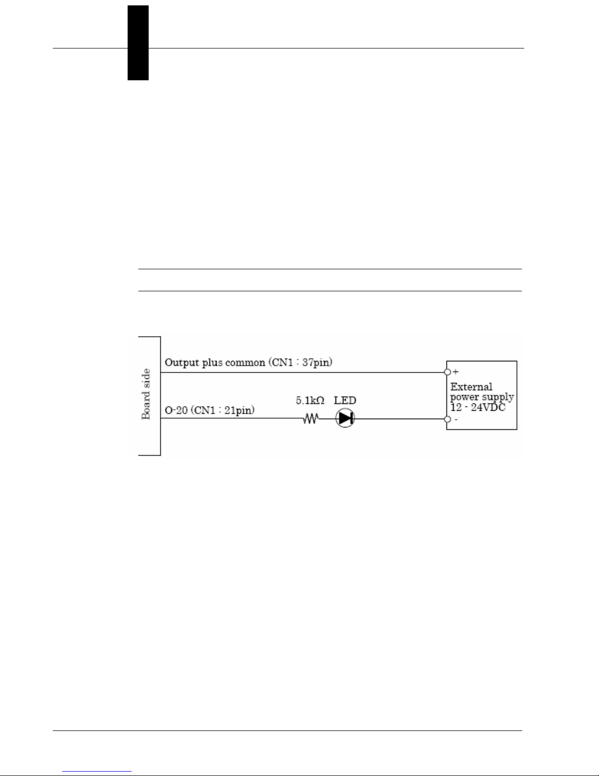
Important: When the PC is turned on, all outputs are reset to OFF.
2
System Components
Connection to an LED
v4.1, November 2011 Visionscape GigE Camera Guide 2-21
Page 32

Chapter 2 System Components
External Strobe and Sensor
For continuous motion or high-speed indexing applications, an external
strobe and sensor may be required to freeze each part before the image
can be acquired.
When choosing your part sensor, you must consider the time interval
between the part passing into the sensing zone and an electrical signal
being generated. When there is a large variation in process speed,
considerable variation in location of the part within the Field of View
(FOV) may result. The FOV specified for the
should be large enough to cover the variation in location.
Power Requirements
Refer to Table 2-3 when determining the power supply requirements for
your GigE Camera.
Visionscape
®
GigE Camera
TABLE 2–3. GigE Camera Power Requirements
Component 24VDC
Visionscape® GigE Camera 24 volts @ 350ma typical
Power Supply Wiring
For complete information about the power supply wiring, see “Power
Connector” on page A-2, and “Visionscape
Pigtail 5M” on page B-2.
(~3.5W)(8Vdc @ 370ma thru
30Vdc @ 120ma)
®
GigE Camera Power M8-3 to
2-22 Visionscape GigE Camera Guide v4.1, November 2011
Page 33

Configuring Your Network Adapter for GigE Visionscape
Configuring Your Network Adapter for GigE Visionscape
GigE cameras need GigE NICs (network interface controllers). NICs can
come built-in to a PC on the motherboard or as PCI or PCIe cards and
there are also some USB-to-Ethernet adapters available.
Microscan recommends the use of NICs that make use of the Intel
Pro/1000 chipsets.
Normally, when you put a NIC into a PC it will be recognized as a network
adapter and will inherit all the usual network protocols. These usually
include the following:
Client for Microsoft Networks
File and Printer Sharing for Microsoft Networks
QoS Packet Scheduler
Internet Protocol (TCP/IP)
Some systems split internet protocol into two separate entries: TCP/IP
Rev 4 and Rev 6. All Microscan cameras use TCP/IP Rev 4.
2
System Components
There may also be anti-virus filters such as “McAfee NDIS Intermediate
Filter”.
GigE cameras should be on their own dedicated network. This has
nothing to do with Microsoft or with sharing. Visionscape installs a
dedicated driver for GigE cameras that is called JAI GigE Vision Filter
Driver. This filter driver recognizes GigE vision packets and filters them so
that the CPU doesn’t have to deal with sorting them out. This lowers the
CPU load, freeing it up for other things.
A GigE vision NIC only needs two items:
JAI GigE Vision Filter Driver
Internet Protocol (TCP/IP) (or TCP/IP Rev 4)
Uncheck all other items from the NIC you want to use for cameras if it will
only be used for cameras. (If you use it for cameras one day and regular
networking the next, leave everything on.)
v4.1, November 2011 Visionscape GigE Camera Guide 2-23
Page 34

Chapter 2 System Components
Important: If you are using a third-party camera and you have installed
that manufacturer’s control software make sure that you disable it in the
Properties dialog below. It will almost certainly conflict with the JAI
software that Visionscape uses to receive images from the cameras.
In the example above, note the two check boxes at the bottom of the
dialog box. If you have these checked then you will see a small icon for
each NIC in the task bar. This is a useful visual indicator of network
status.
2-24 Visionscape GigE Camera Guide v4.1, November 2011
Page 35

Configuring Your Network Adapter for GigE Visionscape
The filter driver requires no setup whatsoever. Clicking on the TCP/IP
Properties button will bring up the following dialog:
2
System Components
There is usually no need for cameras to be on a DHCP network, so
choose a static address that starts with 192.168.x.x. 192.168 is reserved
for private networks. In the picture above the address is set to
192.168.254.2 with the subnet mask set to 255.255.255.0. The mask
means that all devices connected to the NIC should have addresses that
start with 192.168.254.x. It is recommended that you steer clear of using
any address that ends with .1 (for instance 192.168.254.1) as this is
sometimes used by networks for gateways (devices that convert one sort
of protocol to another).
In addition, you should not use any address like 192.168.x.254 because
the GigE driver looks at the last number (254) and enumerates all
cameras on the NIC with addresses above that. In the case of the NIC
ending in 254 the first camera would end in 255, which will not work.
v4.1, November 2011 Visionscape GigE Camera Guide 2-25
Page 36

Chapter 2 System Components
Microscan recommends that you set your NIC to end in .2. For instance
192.168.2.2. If you have more than one camera NIC then set the second
one to 192.168.3.2, and so on.
Optimizing the Network Adapter for use with GigE Cameras
To reduce the load on the PC to a minimum you need to optimize the NIC.
Visionscape does not perform this optimization because every installation
has different requirements and every NIC has different limitations.
Optimization is performed as follows:
Navigate to the network adapter properties and click on the Configure
button next to the network card description:
Clicking the Configure button should bring up the following dialog:
2-26 Visionscape GigE Camera Guide v4.1, November 2011
Page 37

Configuring Your Network Adapter for GigE Visionscape
Next, click on the Advanced tab and you should see a list of parameters
that can be tuned by the user.
2
System Components
Look for Jumbo Frames (sometimes called Jumbo Packets). Set this to
the maximum available – typically 9014 bytes but only 4k or 5k on some
NICs.
v4.1, November 2011 Visionscape GigE Camera Guide 2-27
Page 38

Chapter 2 System Components
Then select Receive Descriptors (if available). This is sometimes grouped
within Performance Options:
Click on the Properties button to bring up this view:
2-28 Visionscape GigE Camera Guide v4.1, November 2011
Page 39

Configuring Your Network Adapter for GigE Visionscape
The default value for receive descriptors is 256. Set this to the maximum
available - typically 2048.
Save changes by clicking OK.
The NIC is now enabled to handle larger packets. This means that,
instead of sending image data from the camera in chunks of 1500 bytes
they can now come in chunks of 9014. That means about 6 times fewer
packets for each image.
Increasing the number of receive descriptors enables the NIC to handle
more packets at any one time. If the processor is busy when an image
arrives, the NIC may not be able to send on the data immediately but data
is still coming in from the camera. These receive descriptors buffer the
system against this. (It is almost essential when using a CMG50 camera).
Attaching and Configuring the Camera(s)
Once you have all this done you can connect your camera directly or plug
in a switch and then connect cameras to that. As they come out of the box
the cameras should now assign themselves addresses in the
192.168.254.x range. They are still receiving information about the
network from outside in order to make this choice. You can simplify things
still further by assigning each camera its own static address.
2
System Components
When you install Visionscape a couple of utilities are installed for you.
These can be found under the Start Menu in:
Start > All Programs > Microscan Visionscape > Tools > Diagnostics
The one we are interested in here is
v4.1, November 2011 Visionscape GigE Camera Guide 2-29
Visionscape GigE Camera IP Config
.
Page 40

Chapter 2 System Components
Open this program and you should see a screen similar to this:
The camera here is set to use DHCP and the address is 192.168.254.3.
However, a persistent IP address is preferable.
Check the “Use persistent IP” box and uncheck the “Use DHCP” box.
Enter 192.168.254.3 in the lower IP address box and 255.255.255.0.
Click Apply. You will be prompted to reboot the camera as follows:
2-30 Visionscape GigE Camera Guide v4.1, November 2011
Page 41

Configuring Your Network Adapter for GigE Visionscape
Cycle power to the camera. The config tool will now show the following:
2
System Components
Now, every time the camera is rebooted it will automatically set this IP
address so it will not have to search the network to determine what IP
address to use.
This is ideal in fixed industrial setups. However, it does mean that you
cannot swap cameras from NIC to NIC or even change the address of the
NIC without setting the camera too.
Now the NIC is set correctly and you need to adjust the way the software
sends the data from the camera to the PC. The NIC “allows” the use of
jumbo packets now but it does not enforce their use. You have to tell
Visionscape to use them. This is done as follows:
Make sure that the dm.config file (C:\Vscape\DM\dm.config) is deleted.
This will give you a clean start. Now boot FrontRunner. This will create a
new dm.config file and populate the Windows registry with default values.
The camera is going to use the default 1500 byte packet size that
Visionscape uses out-of-the-box. You need to change this before going
any further. These values are stored in the registry. From the Start menu
select Run… and type:
Regedit
v4.1, November 2011 Visionscape GigE Camera Guide 2-31
Page 42

Chapter 2 System Components
Then go to:
My Computer\HKEY_LOCAL_MACHINE\SOFTWARE\Visionscape\
GigEVision\Camera_0
Note: In newer builds of Visionscape there are more entries in these
directories.
Depending on how many cameras you have connected you may have
Camera_0, Camera_1, Camera_2 and Camera_3 directories – these all
have the same things inside. You’ll need to repeat the procedure for
Camera_0 on all 4 cameras.
The two parameters InterPacketDelay and PacketSize are both set to 0,
which tells Visionscape to use its default values. The first thing you need
to do is set the PacketSize to 9014. Right-click on PacketSize (the actual
word) and select Modify. You’ll see the following:
2-32 Visionscape GigE Camera Guide v4.1, November 2011
Page 43

Configuring Your Network Adapter for GigE Visionscape
Change Base to Decimal:
Now enter 9014 in the Value Data text box:
2
System Components
Click on OK and you are done for setting the packet size.
You’ve told Visionscape to use jumbo packets but the camera is still going
to be sending data at the same rate – as fast as possible.
Setting the Inter-Packet Delay
There is no reason to have a camera capable of sending data at 90
frames per second if your particular application only runs at 30 frames per
second. It makes a lot more sense (and puts a lot less stress on the PC)
to slow the camera down to the point where it is still fast enough to run
faster than the inspection requirements but not much faster. Let’s give the
application 10% headroom and say that for our 30 frames per second
application we feel safe with the camera running at 33 frames per second.
In other words, we need to slow down the camera to make sure that the
PC can handle the throughput. This is not an issue on PCs with dedicated
PCIe x16 graphics cards but it most certainly is on slower devices.
v4.1, November 2011 Visionscape GigE Camera Guide 2-33
Page 44

Chapter 2 System Components
The inter-packet delay is the parameter that will allow us to control the
rate of data from the camera.
Let’s assume that we are using a CMG03c camera transmitting bayer
data. This camera is capable of running at 91 fps with an 8 millisecond
exposure time. With a 9000 byte packet size one frame of data (656 x 494
= 324,064 bytes + a small overhead) can be transmitted in 38 packets.
The actual data from the camera will be sent over the network at the clock
rate which, for gigabit Ethernet, is 125MHz. This is 8 nanoseconds per
clock. Assuming no overhead and no delays between packets our frame
of data from the CMG03c would take 324,064 clocks, which is 2.59
milliseconds. There is nothing we can do to change this time to transfer
the data.
With the InterPacketDelay (IPD) set to zero the camera sends one packet
of data and then immediately sends the next (actually there is a minimum
delay of approximately 96 nanoseconds). This process repeats until all
the packets that make up an image have been transmitted. Increasing the
IPD tells the camera to take a short break between sending each packet,
which might give other devices a chance to send some of their data.
We can put a delay between each packet. The inter-packet delay is set in
“ticks”, where there are 31,250,000 ticks in one second. From this we
know that 1 tick is 32 nanoseconds.
Let’s assume that we want our camera to run at 33 fps. In this case 1
frame is equal to 30.3 milliseconds. We can take off the fixed data
transmission time of 2.59 milliseconds and that leaves us 27.71
milliseconds. With 38 packets per image that means that every packet
needs to take 729 microseconds.
Dividing 729,000 nanoseconds by 32 nanoseconds gives us a tick count
of 22,781. This is the inter-packet delay we need to put in the Visionscape
registry entry.
The following calculations show how this works in reverse:
– 22,781 ticks is 729 microseconds.
– A 2MB image is approximately 38 9k packets.
– 38 * 729 microseconds = 27.71 milliseconds.
2-34 Visionscape GigE Camera Guide v4.1, November 2011
Page 45

Configuring Your Network Adapter for GigE Visionscape
– Add in the 2.59 milliseconds to actually send the data. 2.59 +
27.71 = 30.3 milliseconds per frame.
– The camera could run at 33 fps.
– Set the inter-packet delay in the registry in exactly the same way
as you set the packet size.
Note: The Visionscape GigE Camera Control Tool includes a tool to
calculate the inter-packet delay. Feel free to use this only when you
understand the material presented here!
FrontRunner Live Video
When you go into Live Video in FrontRunner with the zoom set to 1, a
frame rate is displayed on the top left corner of the picture. For instance, it
might say 30.1 fps. This means that Visionscape is displaying images at
30.1 fps. It does not
fact, it means that the camera is running at least twice as fast as that. This
is due to the way FrontRunner handles live video from the camera.
Imagine that you are using a CMG03c, a VGA camera that can output
data at slightly more than 90 fps. The display on the PC can probably only
manage 60 fps. FrontRunner works as follows:
mean that the camera is running at this rate and, in
2
System Components
The camera is put into a continuous acquisition mode. If the inter-packet
delay is negligible it will indeed be acquiring frames at 90 fps.
FrontRunner will take a frame and then process it before displaying it onscreen. This process is sequential and FrontRunner will not take another
frame until it has finished with the image display. It is not “pipelining” the
process the way it does when acquiring images at runtime with triggers.
The sequential nature of the capture-draw-capture-draw process means
that the best FrontRunner can ever do is 50% of the camera frame rate.
This also depends on how fast the memory is, how fast the CPU itself is,
and how fast the drawing operations are. It may in fact take more than the
frame time to complete the drawing in which case FrontRunner will only
show one in three frames.
Experiments on a Core2Duo workstation with a dedicated graphics card
and an Intel Pro/1000 NIC connected to a CMG03c camera showed that
the maximum frame rate for live video in FrontRunner was 36.9 frames
v4.1, November 2011 Visionscape GigE Camera Guide 2-35
Page 46

Chapter 2 System Components
per second. Furthermore, this was not when the packet size was
minimized but when it was set to 9000.
The rate shown in FrontRunner is the display rate. The camera itself is
running at least twice as fast. The rate displayed on-screen when in live
video is meaningless in terms of the application runtime performance.
Dropped or Missing Packets Message
Live video does however stress the PC more than the runtime. If you
have reduced the camera frame rate using packet size and inter-packet
delay to the rate at which you absolutely must run and you get “Dropped
Packets” messages when running in live video, then your PC is not
capable of running the application and you should find a faster PC. The
usual reason for this is the graphics adapter. Any onboard adapter that
uses shared memory is going to have problems.
The “Dropped Packets” message means that the NIC could not send data
to the system memory in time because the memory or data bus was too
busy. As mentioned above, an onboard or integrated graphics adapter
using shared memory uses the bus extensively. A dedicated graphics
adapter is given the data it needs to display and handles all manipulations
required within its own memory space, thus freeing the system memory bus.
2-36 Visionscape GigE Camera Guide v4.1, November 2011
Page 47

How to Modify the dm.config File to Change Camera and System Assignments
How to Modify the dm.config File to Change Camera and
System Assignments
Explaining and Modifying the dm.config file
The first time you plug a Microscan GigE camera into a PC and start
FrontRunner, a new file is created. This file is called dm.config and it can
be found in the C:\Vscape\DM directory. DM stands for Device Manager,
and this file is intended to manage all GigE devices attached to the PC.
Assuming you have a single GigE camera, the dm.config file will look
similar to that shown below:
<?xml version="1.0" encoding="utf-8"?>
<DMConfiguration xmlns:xsi="http://www.w3.org/2001/XMLSchema-
instance" xmlns:xsd="http://www.w3.org/2001/XMLSchema">
<Settings>
<servicePort>8899</servicePort>
<serviceBase>http://localhost</serviceBase>
<path>DM</path>
<enableLogging>true</enableLogging>
<engineExePath>C:\dev\EngineSolution\EngineProcess\bin\Debug\Vision
scape.EngineProcess.exe</engineExePath>
</Settings>
<Devices>
<Device name="GigEVision1" devClass="GigE">
<Assignments>
<Assignment type="ACQ" uid="94d2afa3-95bb-4e6d-83bd-
098e5ed439d2" />
</Assignments>
</Device>
<Device name="SoftSys1" devClass="Software" />
</Devices>
<Resources>
<Resource uid="94d2afa3-95bb-4e6d-83bd-098e5ed439d2"
type="GigE_Camera" MACAddress="00-06-BE-00-09-4A">
<gige>
<CameraID>TL=>GevTL , INT=>FD::MAC->00-1B-21-0A-0C-
72::National Instruments GigE Vision Adapter - Packet Scheduler
Miniport , DEV=>::MAC->00-06-BE-00-09-4A::Baumer
Optronic::VISIONSCAPE CMG20</CameraID>
<IPAddress>192.168.254.3</IPAddress>
<MACAddress>00-06-BE-00-09-4A</MACAddress>
<VendorName>Microscan</VendorName>
<ResolutionX>1624</ResolutionX>
<ResolutionY>1236</ResolutionY>
<ModelName>VISIONSCAPE CMG20</ModelName>
</gige>
</Resource>
</Resources>
</DMConfig
2
System Components
v4.1, November 2011 Visionscape GigE Camera Guide 2-37
Page 48

Chapter 2 System Components
This file, in XML format, has three main sections. The first section,
settings, can be ignored. The second section, which starts with the
<Devices> line, outlines all the devices (other than smart cameras) that
will be listed in the FrontRunner device bar. In the example above, there
are two devices – GigE Vision1 and SoftSys1.
The third section, starting with the <Resources> line, lists all the GigE
cameras attached to the network cards. Note that only cameras that are
connected via gigabit ethernet will be listed. We do not recommend or
even allow the use of 100baseT networks with Microscan GigE cameras.
If you look closely, you'll notice that the assignment uid listed in the device
section is the same as that shown for the resource uid for the attached
camera.
If you open the Visionscape Backplane debug window, you will see the
same information again:
10:41:37 QuerySWRights: GigE license rights detected, features:
Visionscape GigE (x8): YES / IntelliFind: YES / Third Party GigE
Cameras: 0 allowed
10:41:39 CreateSystemsFromConfigFile: found 2 devices in dm.config
file
10:41:39 Creating GigE System 1: GigEVision1
10:41:39 Channel 0 (Filter Driver): Microscan VISIONSCAPE
CMG20 (1624x1236) MAC="00-06-BE-00-09-4A" IP="192.168.254.3"
Connected
10:41:39 Creating SW System 1: SoftSys1
10:41:40 Creating IO Server for System GigEVision1
10:41:41 Creating IO Server for System SoftSys1
Now let’s quit FrontRunner and the Backplane and add a second camera
to our network. Once the second cameras is plugged in, the network card
will take a little while to recognize and configure it, so don't start
FrontRunner immediately.
If you look at the dm.config file now you will see that it looks similar to this:
<?xml version="1.0" encoding="utf-8"?>
<DMConfiguration xmlns:xsi="http://www.w3.org/2001/XMLSchema-
instance" xmlns:xsd="http://www.w3.org/2001/XMLSchema">
<Settings>
<servicePort>8899</servicePort>
<serviceBase>http://localhost</serviceBase>
<path>DM</path>
<enableLogging>true</enableLogging>
<engineExePath>C:\dev\EngineSolution\EngineProcess\bin\Debug\Vision
scape.EngineProcess.exe</engineExePath>
</Settings>
2-38 Visionscape GigE Camera Guide v4.1, November 2011
Page 49

How to Modify the dm.config File to Change Camera and System Assignments
<Devices>
<Device name="GigEVision1" devClass="GigE">
<Assignments>
<Assignment type="ACQ" uid="94d2afa3-95bb-4e6d-83bd-
098e5ed439d2" />
<Assignment type="ACQ" uid="189b1b90-624b-4eec-b282-
839558dc0f6c" />
</Assignments>
</Device>
<Device name="SoftSys1" devClass="Software" />
</Devices>
<Resources>
<Resource uid="94d2afa3-95bb-4e6d-83bd-098e5ed439d2"
type="GigE_Camera" MACAddress="00-06-BE-00-09-4A">
<gige>
<CameraID>TL=>GevTL , INT=>FD::MAC->00-1B-21-0A-0C-
72::National Instruments GigE Vision Adapter - Packet Scheduler
Miniport , DEV=>::MAC->00-06-BE-00-09-4A::Baumer
Optronic::VISIONSCAPE CMG20</CameraID>
<IPAddress>192.168.254.3</IPAddress>
<MACAddress>00-06-BE-00-09-4A</MACAddress>
<VendorName>Microscan</VendorName>
<ResolutionX>1624</ResolutionX>
<ResolutionY>1236</ResolutionY>
<ModelName>VISIONSCAPE CMG20</ModelName>
</gige>
</Resource>
<Resource uid="189b1b90-624b-4eec-b282-839558dc0f6c"
type="GigE_Camera" MACAddress="00-06-BE-00-09-4B">
<gige>
<CameraID>TL=>GevTL , INT=>FD::MAC->00-1B-21-0A-0C-
72::National Instruments GigE Vision Adapter - Packet Scheduler
Miniport , DEV=>::MAC->00-06-BE-00-09-4B::Baumer
Optronic::VISIONSCAPE CMG20</CameraID>
<IPAddress>192.168.254.2</IPAddress>
<MACAddress>00-06-BE-00-09-4B</MACAddress>
<VendorName>Microscan</VendorName>
<ResolutionX>1624</ResolutionX>
<ResolutionY>1236</ResolutionY>
<ModelName>VISIONSCAPE CMG20</ModelName>
</gige>
</Resource>
</Resources>
</DMConfiguration>
2
System Components
The GigEVision1 system now contains two assignments and there is a
second camera resource at the bottom of the file.
The debug window now shows two cameras on GigEVision1:
11:19:11 QuerySWRights: GigE license rights detected, features:
Visionscape GigE (x8): YES / IntelliFind: YES / Third Party GigE
Cameras: 0 allowed
11:19:13 CreateSystemsFromConfigFile: found 2 devices in dm.config
file
11:19:13 Creating GigE System 1: GigEVision1
v4.1, November 2011 Visionscape GigE Camera Guide 2-39
Page 50

Chapter 2 System Components
11:19:13 Channel 0 (Filter Driver): Microscan VISIONSCAPE
CMG20 (1624x1236) MAC="00-06-BE-00-09-4A" IP="192.168.254.3"
Connected
11:19:13 Channel 1 (Filter Driver): Microscan VISIONSCAPE
CMG20 (1624x1236) MAC="00-06-BE-00-09-4B" IP="192.168.254.2"
Connected
11:19:13 Creating SW System 1: SoftSys1
11:19:15 Creating IO Server for System GigEVision1
11:19:16 Creating IO Server for System SoftSys1
If you look at the FrontRunner device bar you will see that there is still
only one GigE device listed:
Create a new job and bring up the editor. Click on the vision system step
on the left and you will see something similar to that shown below:
There are the two cameras both now available for use in the new job.
Suppose you want to break your cameras down so that, instead of all
being part of one big system, they are on separate systems. Why might
you want to do this? Maybe it makes more sense to your physical layout
this way. For example, if you have one Visionscape system with four
cameras each monitoring a process on four separate lines, then you
might want to stop one line and change the job being run while still
2-40 Visionscape GigE Camera Guide v4.1, November 2011
Page 51

How to Modify the dm.config File to Change Camera and System Assignments
running the other three lines. This is theoretically possible with multiple
GigE systems.
How do you do this? By making some relatively simple changes to the
dm.config file. Start by quitting FrontRunner and the Backplane.
Taking our two camera file as a starting point, we are going to duplicate
the GigEVision1 device as follows. (Only the device part of the file is
shown here):
<Devices>
<Device name="GigEVision1" devClass="GigE">
<Assignments>
<Assignment type="ACQ" uid="94d2afa3-95bb-4e6d-83bd-
098e5ed439d2" />
<Assignment type="ACQ" uid="189b1b90-624b-4eec-b282-
839558dc0f6c" />
</Assignments>
</Device>
<Device name="SoftSys1" devClass="Software" />
</Devices>
Copy everything for the first device and paste it immediately above the
SoftSys1 device as follows:
<Devices>
<Device name="GigEVision1" devClass="GigE">
<Assignments>
<Assignment type="ACQ" uid="94d2afa3-95bb-4e6d-83bd-
098e5ed439d2" />
<Assignment type="ACQ" uid="189b1b90-624b-4eec-b282-
839558dc0f6c" />
</Assignments>
</Device>
<Device name="GigEVision1" devClass="GigE">
<Assignments>
<Assignment type="ACQ" uid="94d2afa3-95bb-4e6d-83bd-
098e5ed439d2" />
<Assignment type="ACQ" uid="189b1b90-624b-4eec-b282-
839558dc0f6c" />
</Assignments>
</Device>
<Device name="SoftSys1" devClass="Software" />
</Devices>
2
System Components
Now delete one uid from each of the two devices and rename the second
one:
<Devices>
<Device name="GigEVision1" devClass="GigE">
<Assignments>
<Assignment type="ACQ" uid="94d2afa3-95bb-4e6d-83bd-
098e5ed439d2" />
</Assignments>
v4.1, November 2011 Visionscape GigE Camera Guide 2-41
Page 52

Chapter 2 System Components
</Device>
<Device name="GigEVision2" devClass="GigE">
<Assignments>
<Assignment type="ACQ" uid="189b1b90-624b-4eec-b282-
839558dc0f6c" />
</Assignments>
</Device>
<Device name="SoftSys1" devClass="Software" />
</Devices>
Bring up FrontRunner again and you should see the following in the
device bar:
Two GigE systems are available, each with one camera.
The Backplane debug window also shows the change:
14:01:47 QuerySWRights: GigE license rights detected, features:
Visionscape GigE (x8): YES / IntelliFind: YES / Third Party GigE
Cameras: 0 allowed
14:01:49 CreateSystemsFromConfigFile: found 3 devices in dm.config
file
14:01:49 Creating GigE System 1: GigEVision1
14:01:49 Channel 0 (Filter Driver): Microscan VISIONSCAPE
CMG20 (1624x618) MAC="00-06-BE-00-09-4A" IP="192.168.254.3"
Connected
14:01:49 Creating GigE System 2: GigEVision2
2-42 Visionscape GigE Camera Guide v4.1, November 2011
Page 53

How to Modify the dm.config File to Change Camera and System Assignments
14:01:49 Channel 0 (Filter Driver): Microscan VISIONSCAPE
CMG20 (1624x618) MAC="00-06-BE-00-09-4B" IP="192.168.254.2"
Connected
14:01:49 Creating SW System 1: SoftSys1
14:01:50 Creating IO Server for System GigEVision1
14:01:51 Creating IO Server for System GigEVision2
14:01:52 Creating IO Server for System SoftSys1
You can now use the two cameras and systems independently. You could
load the same job on both systems.
Remember that, if using the Visionscape PCIe digital IO card, all systems
share this resource. Make sure that you're not trying to use the same
output line for two or more things.
2
Switching Out a Camera
Imagine you have a production system with several cameras. All is
working well but then someone manages to break one of the cameras. A
spare camera is procured and put on the network in place of the damaged
device. Will Visionscape automatically detect this change for you?
The answer is no, not in the current version of Visionscape. What will
happen is that the new camera will be added to the end of the resources
list in the dm.config file. The uid for the new camera will be automatically
added to the end of the GigEVision1 list. This probably isn't what you
want. In addition, the original, broken camera will still have entries in the
dm.config file – the software doesn't know it is broken.
Let's go back to our original dm.config file. We have one camera attached
as shown in the listing below:
<?xml version="1.0" encoding="utf-8"?>
<DMConfiguration xmlns:xsi="http://www.w3.org/2001/XMLSchema-
instance" xmlns:xsd="http://www.w3.org/2001/XMLSchema">
<Settings>
<servicePort>8899</servicePort>
<serviceBase>http://localhost</serviceBase>
<path>DM</path>
<enableLogging>true</enableLogging>
<engineExePath>C:\dev\EngineSolution\EngineProcess\bin\Debug\Vision
scape.EngineProcess.exe</engineExePath>
</Settings>
<Devices>
<Device name="GigEVision1" devClass="GigE">
<Assignments>
<Assignment type="ACQ" uid="2ca5cfd1-14c2-45dd-b692-
9a2948d18361" />
</Assignments>
System Components
v4.1, November 2011 Visionscape GigE Camera Guide 2-43
Page 54

Chapter 2 System Components
</Device>
<Device name="SoftSys1" devClass="Software" />
</Devices>
<Resources>
<Resource uid="2ca5cfd1-14c2-45dd-b692-9a2948d18361"
type="GigE_Camera" MACAddress="00-06-BE-00-09-4B">
<gige>
<CameraID>TL=>GevTL , INT=>FD::MAC->00-1B-21-0A-0C-
72::National Instruments GigE Vision Adapter - Packet Scheduler
Miniport , DEV=>::MAC->00-06-BE-00-09-4B::Baumer
Optronic::VISIONSCAPE CMG20</CameraID>
<IPAddress>192.168.254.2</IPAddress>
<MACAddress>00-06-BE-00-09-4B</MACAddress>
<VendorName>Microscan</VendorName>
<ResolutionX>1624</ResolutionX>
<ResolutionY>618</ResolutionY>
<ModelName>VISIONSCAPE CMG20</ModelName>
</gige>
</Resource>
</Resources>
</DMConfiguration>
The vision system step shows this one camera as being available for use.
Everything is as it should be.
Now we are going to shut Visionscape down and change the camera to
another one. This camera is then added to the dm.config list.
<?xml version="1.0" encoding="utf-8"?>
<DMConfiguration xmlns:xsi="http://www.w3.org/2001/XMLSchema-
instance" xmlns:xsd="http://www.w3.org/2001/XMLSchema">
<Settings>
<servicePort>8899</servicePort>
<serviceBase>http://localhost</serviceBase>
<path>DM</path>
<enableLogging>true</enableLogging>
<engineExePath>C:\dev\EngineSolution\EngineProcess\bin\Debug\Vision
scape.EngineProcess.exe</engineExePath>
</Settings>
<Devices>
<Device name="GigEVision1" devClass="GigE">
<Assignments>
<Assignment type="ACQ" uid="2ca5cfd1-14c2-45dd-b692-
9a2948d18361" />
2-44 Visionscape GigE Camera Guide v4.1, November 2011
Page 55

How to Modify the dm.config File to Change Camera and System Assignments
<Assignment type="ACQ" uid="07a05837-f79e-4827-8773399c72bb1d63" />
</Assignments>
</Device>
<Device name="SoftSys1" devClass="Software" />
</Devices>
<Resources>
<Resource uid="2ca5cfd1-14c2-45dd-b692-9a2948d18361"
type="GigE_Camera" MACAddress="00-06-BE-00-09-4B">
<gige>
<CameraID>TL=>GevTL , INT=>FD::MAC->00-1B-21-0A-0C-
72::National Instruments GigE Vision Adapter - Packet Scheduler
Miniport , DEV=>::MAC->00-06-BE-00-09-4B::Baumer
Optronic::VISIONSCAPE CMG20</CameraID>
<IPAddress>192.168.254.2</IPAddress>
<MACAddress>00-06-BE-00-09-4B</MACAddress>
<VendorName>Microscan</VendorName>
<ResolutionX>1624</ResolutionX>
<ResolutionY>618</ResolutionY>
<ModelName>VISIONSCAPE CMG20</ModelName>
</gige>
</Resource>
<Resource uid="07a05837-f79e-4827-8773-399c72bb1d63"
type="GigE_Camera" MACAddress="00-06-BE-00-09-4A">
<gige>
<CameraID>TL=>GevTL , INT=>FD::MAC->00-1B-21-0A-0C-
72::National Instruments GigE Vision Adapter - Packet Scheduler
Miniport , DEV=>::MAC->00-06-BE-00-09-4A::Baumer
Optronic::VISIONSCAPE CMG20</CameraID>
<IPAddress>192.168.254.2</IPAddress>
<MACAddress>00-06-BE-00-09-4A</MACAddress>
<VendorName>Microscan</VendorName>
<ResolutionX>0</ResolutionX>
<ResolutionY>0</ResolutionY>
<ModelName>VISIONSCAPE CMG20</ModelName>
</gige>
</Resource>
</Resources>
</DMConfiguration>
2
System Components
The original camera is still in the file and the new one has been added to
GigEVision1 below it.
The debug window also noted the change – it lets you know that the
original camera couldn't be found.
16:23:58 QuerySWRights: GigE license rights detected, features:
Visionscape GigE (x8): YES / IntelliFind: YES / Third Party GigE
Cameras: 0 allowed
16:24:05 CreateSystemsFromConfigFile: found 2 devices in dm.config
file
16:24:05 Creating GigE System 1: GigEVision1
16:24:05 Channel 0 (Filter Driver): Microscan VISIONSCAPE
CMG20 (1624x618) MAC="00-06-BE-00-09-4B" IP="192.168.254.2" Not
connected
16:24:05 Channel 1 (Filter Driver): Microscan VISIONSCAPE
CMG20 (0x0) MAC="00-06-BE-00-09-4A" IP="192.168.254.2" Connected
v4.1, November 2011 Visionscape GigE Camera Guide 2-45
Page 56

Chapter 2 System Components
16:24:05 Creating SW System 1: SoftSys1
16:24:10 Creating IO Server for System GigEVision1
16:24:11 Creating IO Server for System SoftSys1
In this state, FrontRunner comes up and, although you only have the one
camera connected, there are two cameras in the vision system step list:
The original camera is still camera 1 although it is noted as being
disconnected. Any job that we were using before would still keep the
same camera channel assignments, so if they were using camera 1
before they will still try to use camera 1 even though it is not there.
We opened a job that had been saved for the first camera and tried to
take a picture. It failed and output the red error bar below the buffer in
FrontRunner. The debug window also informed us that this was not going
to work:
16:31:33 GigeVision1: No Acquisition control! There is no control
connection for Camera 1
16:31:33 GigEVision1: Camera 1 Not Detected -- Check the camera,
camera power, and cable !
Live video will still start but won't do anything.
Warning: If you are using a slow laptop then it could also be hard to stop.
We need to get back to where the same jobs will load in the same way as
before but will use the new camera instead. We need to edit the dm.config
file. Again, be sure to quit FrontRunner and the Backplane before
attempting this.
2-46 Visionscape GigE Camera Guide v4.1, November 2011
Page 57

How to Modify the dm.config File to Change Camera and System Assignments
If the original camera is no longer required, delete it by erasing the first
line in the GigEVision1 assignments as follows:
Before
<Devices>
<Device name="GigEVision1" devClass="GigE">
<Assignments>
<Assignment type="ACQ" uid="2ca5cfd1-14c2-45dd-b692-
9a2948d18361" />
<Assignment type="ACQ" uid="07a05837-f79e-4827-8773-
399c72bb1d63" />
</Assignments>
</Device>
<Device name="SoftSys1" devClass="Software" />
</Devices>
After
<Devices>
<Device name="GigEVision1" devClass="GigE">
<Assignments>
<Assignment type="ACQ" uid="07a05837-f79e-4827-8773-
399c72bb1d63" />
</Assignments>
</Device>
<Device name="SoftSys1" devClass="Software" />
</Devices>
You could leave the resources entry in the file but it is cleaner to delete it
(make sure you delete the correct one – use the uid from the original
camera from the line you just deleted).
2
System Components
Before
<Resources>
<Resource uid="2ca5cfd1-14c2-45dd-b692-9a2948d18361"
type="GigE_Camera" MACAddress="00-06-BE-00-09-4B">
<gige>
<CameraID>TL=>GevTL , INT=>FD::MAC->00-1B-21-0A-0C-
72::National Instruments GigE Vision Adapter - Packet Scheduler
Miniport , DEV=>::MAC->00-06-BE-00-09-4B::Baumer
Optronic::VISIONSCAPE CMG20</CameraID>
<IPAddress>192.168.254.2</IPAddress>
<MACAddress>00-06-BE-00-09-4B</MACAddress>
<VendorName>Microscan</VendorName>
<ResolutionX>1624</ResolutionX>
<ResolutionY>618</ResolutionY>
<ModelName>VISIONSCAPE CMG20</ModelName>
</gige>
</Resource>
<Resource uid="07a05837-f79e-4827-8773-399c72bb1d63"
type="GigE_Camera" MACAddress="00-06-BE-00-09-4A">
<gige>
<CameraID>TL=>GevTL , INT=>FD::MAC->00-1B-21-0A-0C-
72::National Instruments GigE Vision Adapter - Packet Scheduler
v4.1, November 2011 Visionscape GigE Camera Guide 2-47
Page 58

Chapter 2 System Components
Miniport , DEV=>::MAC->00-06-BE-00-09-4A::Baumer
Optronic::VISIONSCAPE CMG20</CameraID>
<IPAddress>192.168.254.2</IPAddress>
<MACAddress>00-06-BE-00-09-4A</MACAddress>
<VendorName>Microscan</VendorName>
<ResolutionX>0</ResolutionX>
<ResolutionY>0</ResolutionY>
<ModelName>VISIONSCAPE CMG20</ModelName>
</gige>
</Resource>
</Resources>
After
<Resources>
<Resource uid="07a05837-f79e-4827-8773-399c72bb1d63"
type="GigE_Camera" MACAddress="00-06-BE-00-09-4A">
<gige>
<CameraID>TL=>GevTL , INT=>FD::MAC->00-1B-21-0A-0C-
72::National Instruments GigE Vision Adapter - Packet Scheduler
Miniport , DEV=>::MAC->00-06-BE-00-09-4A::Baumer
Optronic::VISIONSCAPE CMG20</CameraID>
<IPAddress>192.168.254.2</IPAddress>
<MACAddress>00-06-BE-00-09-4A</MACAddress>
<VendorName>Microscan</VendorName>
<ResolutionX>0</ResolutionX>
<ResolutionY>0</ResolutionY>
<ModelName>VISIONSCAPE CMG20</ModelName>
</gige>
</Resource>
</Resources>
We should now be able to bring up FrontRunner again and only see the
one camera. We should also be able to run jobs from our original camera
on this new device (assuming they are the same type of camera).
Everything looks fine in the debug window:
16:41:54 QuerySWRights: GigE license rights detected, features:
Visionscape GigE (x8): YES / IntelliFind: YES / Third Party GigE
Cameras: 0 allowed
16:41:56 CreateSystemsFromConfigFile: found 2 devices in dm.config
file
16:41:56 Creating GigE System 1: GigEVision1
16:41:56 Channel 0 (Filter Driver): Microscan VISIONSCAPE
CMG20 (1624x1236) MAC="00-06-BE-00-09-4A" IP="192.168.254.2"
Connected
16:41:56 Creating SW System 1: SoftSys1
16:41:57 Creating IO Server for System GigEVision1
16:41:58 Creating IO Server for System SoftSys1
This is certainly not as simple as it was when all you had to do to replace
a camera was unplug the old one and plug in the replacement – but it’s
not rocket science either.
2-48 Visionscape GigE Camera Guide v4.1, November 2011
Page 59

How to Modify the dm.config File to Change Camera and System Assignments
If you find yourself running demonstrations from a laptop for customers or
other users and you have more than one GigE camera, be sure to follow
the guidelines from the last few pages. If you don't, you won't be able to
demonstrate the software as cleanly as you would otherwise. Microscan
recommends that you delete the dm.config file before running a GigE
demonstration. The file will be created correctly the first time you start up
FrontRunner. If you really don't want to delete it then give it a new name
so you can go back to it later.
Partial Scan Acquisition
All of the new Visionscape GigE cameras support partial scan mode. This
is easy to use if you don’t mind “getting your hands dirty” modifying the
camera definition file. Here’s how to do it.
Imagine you’re using a CMG03. The camdef file is in the
C:\Vscape\Drivers\CamDefs directory and it’s called:
2
System Components
microscan_visionscape_cmg03_656x494_gigevision.cam
Open this file with the text editor of your choice (Notepad, for example). It
looks like this:
Camera Name Microscan VISIONSCAPE CMG03 656x494
Digitizer Type 1073741824 // GigeVision
Camera Help File
Stride 656
Rows 494
X Offset 0
Y Offset 0
Bits Per Pixel 8
Pixel Type 0
Image Structure 1
Vertical Binning 1
Horizontal Binning 1
Async Control 1 // 1=async, 0=continuous (formerly "shutter
type")
Usecs Per Frame 33333
Usecs Per Line x 10 674
Sensors 1
Strobes 1
GPIO Edit Mask 0x0
GPIO Defaults 0x0
GPIO Count 0
GPIO Inputs 0
GPIO Outputs 0
v4.1, November 2011 Visionscape GigE Camera Guide 2-49
Page 60

Chapter 2 System Components
If you only want to use the middle 100 lines you would change this as
follows:
Camera Name Microscan VISIONSCAPE CMG03 656x100
Digitizer Type 1073741824 // GigeVision
Camera Help File
Stride 656
Rows 100
X Offset 0
Y Offset 197
Bits Per Pixel 8
Pixel Type 0
Image Structure 1
Vertical Binning 1
Horizontal Binning 1
Async Control 1 // 1=async, 0=continuous (formerly "shutter
type")
Usecs Per Frame 33333
Usecs Per Line x 10 674
Sensors 1
Strobes 1
GPIO Edit Mask 0x0
GPIO Defaults 0x0
GPIO Count 0
GPIO Inputs 0
GPIO Outputs 0
Setting the Y Offset to 197 because 494-100 = 394. 394/2 = 197. 197
lines to ignore, take 100 lines and ignore the rest. Save this file, making
sure that you do not
save it as a text file (Save as Type… All Files).
Load FrontRunner and you should now be able to select this new camdef
for your camera.
How to Set Up a Multiple-Camera System the Easy Way
Imagine that a customer wants to use four CMG20 cameras in a single
inspection. The cameras will be connected to a single NIC through a GigE
switch.
If they just plug in all four cameras and turn them on, two things will
happen:
• The order of the four cameras may not be what the customer wants;
• They won’t work taking simultaneous images because the overall
bandwidth of these four cameras is too high (the CMG20 can do 16
fps. At 2MB per image, this is 32MB per second per camera. 4
2-50 Visionscape GigE Camera Guide v4.1, November 2011
Page 61

How to Modify the dm.config File to Change Camera and System Assignments
cameras give 128MB per second which is more than the 1000Base/T
link can handle).
The Correct Procedure
The first thing to do is to make sure that the NIC is configured correctly.
Hopefully this is an Intel Pro/1000 NIC card. If so, go to the network
adapter properties and click on the Configure button next to the network
card description:
Next, click on the Advanced tab and you should see a list of parameters
that can be tuned by the user.
Look for Jumbo Frames (sometimes called Jumbo Packets) and
Receive Descriptors (sometimes called Receive Buffers). On some
drivers these may be buried inside Performance Options.
2
System Components
Jumbo Frames: Make sure this is set to the maximum available – typically
9014 bytes but only 5k on some NICs.
Receive Descriptors: Set this to the maximum – typically 2048.
Save the changes.
You have just enabled the NIC to handle larger packets. This means that,
instead of sending image data from the camera in chunks of 1500 bytes
they can now come in chunks of 9014. That means about six times fewer
packets for each image.
Increasing the number of receive descriptors enables the NIC to handle
more packets at any one time. If the processor is busy when an image
arrives, the NIC may not be able to send on the data immediately, but
data is still coming in from the camera. These receive descriptor buffer
the system against this. (It is almost essential when using a CMG50
camera).
v4.1, November 2011 Visionscape GigE Camera Guide 2-51
Page 62

Chapter 2 System Components
Now that the NIC is all set up to handle cameras in the most efficient way
possible we can start working with the cameras.
3. Connect the switch to the NIC and turn it on.
4. Connect the camera you want to be camera 1 to the NIC.
5. Bring up FrontRunner or just the Backplane. (Just the Backplane is
much faster). As this is the first time that you have booted the
Visionscape software, a new file, C:\Vscape\DM\dm.config, will be
created.
[If this wasn’t the first time you have run FrontRunner then quit
FrontRunner and the Backplane and delete dm.config before going
back to step 1].
6. Close the Backplane – you can do this by right-clicking on the icon in
the taskbar.
7. Connect the second camera and repeat steps 3 and 4.
8. Repeat step 5 for cameras 3 and 4.
You have now attached all four cameras to the switch and the
Visionscape software saw them each in order. This will have made the
dm.config file remember the order.
The four cameras are still not quite ready to use. They are still going to
use the default 1500 byte packet size that Visionscape uses out-of-thebox. We need to change this before going any further. These values are
stored in the registry. From the Start menu select Run… and type:
Regedit
2-52 Visionscape GigE Camera Guide v4.1, November 2011
Page 63

How to Modify the dm.config File to Change Camera and System Assignments
Go to My Computer\HKEY_LOCAL_MACHINE\SOFTWARE
\Visionscape\GigEVision\Camera_0
You will actually have Camera_0, Camera_1, Camera_2 and Camera_3
directories – these all have the same things inside. You’ll need to repeat
the procedure for Camera_0 on all 4 cameras.
2
System Components
The two parameters InterPacketDelay and PacketSize are both set to 0,
which tells Visionscape to use its default values. The first thing you need
to do is set the PacketSize to 9014. To do this, right-click on PacketSize
and select Modify. You’ll see the following:
v4.1, November 2011 Visionscape GigE Camera Guide 2-53
Page 64

Chapter 2 System Components
Change to Decimal in the Base group:
Now enter 9014 in the Value Data text box:
Click OK and you are done setting the packet size. Repeat this for all four
cameras.
We’ve told Visionscape to use jumbo packets but the four cameras are
still going to be sending data at the same rate (128MB per second
overall). What this means is that one camera will start sending a solid
stream of data, another camera will try to do the same thing but find that
the network is completely snarled and the result will be that image data
will be lost.
We need to slow down the cameras now so that they’ll work nicely
together – this is what InterPacketDelay is for.
2-54 Visionscape GigE Camera Guide v4.1, November 2011
Page 65

How to Modify the dm.config File to Change Camera and System Assignments
With the InterPacketDelay (IPD) set to zero the camera sends one packet
of data and then immediately sends the next (actually there is a minimum
delay of approximately 96 nanoseconds). This process repeats until all
the packets that make up an image have been transmitted. Increasing the
IPD tells the camera to take a short break between sending each packet
which might give other devices a chance to send some of their data.
The IPD is a multiple of ticks. For GigE, 1 tick is 16 nanoseconds. To run
4 CMG20 cameras at a maximum of 5 frames per second setting the IPD
to 15000 works. This is a delay of 240 microseconds between each
packet.
The following calculations show how this works:
2
– 15,000 ticks is 240 microseconds.
– 2MB image is approximately 222 9k packets.
– 222 * 240 microseconds = 53 milliseconds.
– The camera could run at 16 fps, which is 62 milliseconds per
frame.
– We have just increased the overall time per frame from 62
milliseconds to 62 + 53 = 115 milliseconds. This is more than 5
frames per second so we should be all set (depending on
exposure time).
The final step is to shut down the Backplane (if it is running) and cycle
power to all the cameras. When Visionscape comes up the next time with
jumbo packets enabled in the registry and the NIC, it will be able to tell the
cameras to use jumbo packets too.
Now you can use the cameras without any missing packets or dropped
frames.
System Components
NIC Parameters
GigE cameras need GigE NICs (network interface controllers). NICs can
come built-in to a PC on the motherboard or as PCI or PCIe cards and
there are also some USB-to-Ethernet adapters available.
Microscan recommends the use of NICs that make use of the Intel
Pro/1000 chipsets.
v4.1, November 2011 Visionscape GigE Camera Guide 2-55
Page 66

Chapter 2 System Components
Normally, when you put a NIC into a PC it will be recognized as a network
adapter and will inherit all the usual network protocols. These usually
include the following:
Client for Microsoft Networks
File and Printer Sharing for Microsoft Networks
QoS Packet Scheduler
Internet Protocol (TCP/IP)
Some systems split internet protocol into two separate entries: TCP/IP
Rev 4 and Rev 6. All Microscan cameras use TCP/IP Rev 4.
There may also be anti-virus filters such as “McAfee NDIS Intermediate
Filter”.
GigE cameras should be on their own dedicated network. This has
nothing to do with Microsoft or with sharing. Visionscape installs a
dedicated driver for GigE cameras that is called JAI GigE Vision Filter
Driver. This filter driver recognizes GigE vision packets and filters them so
that the CPU doesn’t have to deal with sorting them out. This lowers the
CPU load, freeing it up for other things.
A GigE vision NIC only needs two items:
JAI GigE Vision Filter Driver
Internet Protocol (TCP/IP) (or TCP/IP Rev 4)
Uncheck all other items from the NIC you want to use for cameras if it will
only be used for cameras. (If you use it for cameras one day and regular
networking the next, leave everything on.)
2-56 Visionscape GigE Camera Guide v4.1, November 2011
Page 67

How to Modify the dm.config File to Change Camera and System Assignments
In the example below, note the two check boxes at the bottom of the
dialog box. If you have these checked then you will see a small icon for
each NIC in the task bar. This is a useful visual indicator of network
status.
2
System Components
v4.1, November 2011 Visionscape GigE Camera Guide 2-57
Page 68

Chapter 2 System Components
The filter driver requires no setup whatsoever. Clicking on the TCP/IP
Properties button will bring up the following dialog:
There is usually no need for cameras to be on a DHCP network, so
choose a static address that starts with 192.168.x.x. 192.168 is reserved
for private networks. In the picture above the address is set to
192.168.254.2 with the subnet mask set to 255.255.255.0. The mask
means that all devices connected to the NIC should have addresses that
start with 192.168.254.x. It is recommended that you steer clear of using
any address that ends with .1 (for instance 192.168.254.1) as this is
sometimes used by networks for gateways (devices that convert one sort
of protocol to another).
You should also optimize the NIC. How to Set Up a Multiple-Camera
System covered setting up the advanced parameters for the NIC (jumbo
packets, receive descriptors, etc.). Make sure you do this for best
performance.
Once you have all this done then you can connect your camera directly or
plug in a switch and then connect cameras to that. As they come out of
2-58 Visionscape GigE Camera Guide v4.1, November 2011
Page 69

How to Modify the dm.config File to Change Camera and System Assignments
the box the cameras should now give themselves addresses in the
192.168.254.x range. They are still getting information about the network
from outside in order to make this choice. You can simplify things still
further by assigning each camera its own static address.
When you install Visionscape a couple of utilities are installed for you.
These can be found under the Start Menu in:
Start-All Programs > Microscan Visionscape > Tools > Diagnostics
2
The one we are interested in here is
Open this program and you should see a screen similar to this:
Visionscape GigE Camera IP Config
.
System Components
The camera here is set to use DHCP and its address is 192.168.254.3.
However, a persistent IP address is preferable.
v4.1, November 2011 Visionscape GigE Camera Guide 2-59
Page 70

Chapter 2 System Components
Check the Use persistent IP box and uncheck the Use DHCP box. Enter
192.168.254.3 in the lower IP address box and 255.255.255.0 for the
Subnet mask. Click Apply. You will be prompted to reboot the camera as
follows:
Cycle power to the camera and you are ready. The config tool will now
show the following:
Now, every time the camera is rebooted it will automatically set this IP
address so it will not have to search the network to determine what IP
address to use.
This is ideal in fixed industrial setups. However, it does mean that you
cannot simply swap cameras from NIC to NIC or even change the
address of the NIC without having to reconfigure the camera address.
2-60 Visionscape GigE Camera Guide v4.1, November 2011
Page 71

How to Modify the dm.config File to Change Camera and System Assignments
What To Do When Visionscape Is Not Working Within
Normal Operational Parameters
Sometimes when you install or upgrade Visionscape (or install something
after Visionscape) things start to work incorrectly. This can be caused by
registration problems. All of the components used for Visionscape are in
the C:\Vscape\412_10\Dll directory.
To ensure that they are all registered you should first make sure that no
Visionscape applications are running (including the AVP Backplane).
Then do the following:
1. Open a command prompt window (type CMD in the Run… box).
2. Navigate to the directory shown above. You can do this by whatever
means you prefer, but a step-by-step way would be to type:
a. cd ..
b. cd ..
c. cd Vscape
d. cd 412_10
e. cd dll
3. Type aregsvr *
2
System Components
4. This will register all the Visionscape components again.
Another problem that some customers have encountered seems to be
related to the installation process, although this affects the dm.config file.
The error seen in the Visionscape debug window looks like this:
CAvpBackplane:: CreateAll From Config file cannot access config file
Exception thrown
One possible fix for this is:
1. Open the command prompt and navigate to the same folder as above.
2. Type the following:
regasm visionscape.configuration.dll /tlb
Again, be sure that all Visionscape components are shut down before
doing this.
For additional assistance, contact Microscan’s help desk at:
helpdesk@microscan.com
.
v4.1, November 2011 Visionscape GigE Camera Guide 2-61
Page 72

Chapter 2 System Components
Visionscape GigE Network Configuration
Visionscape GigE cameras should be configured on private networks in
the manner described in Section 2 of this manual. Cameras may either be
connected directly to a PC network “Ethernet” port or wired indirectly
through a GigE switch such as PN 98-000131-01.
The Visionscape GigE is configured by default with network parameters
governing packet size and the intervals between packets that allow single
GigE cameras of all sensor sizes to operate at full rated speed. The
automatically selected parameters will also allow multiple (up to 4)
standard resolution (VGA) cameras such as the 98-000115-01 (CMG03)
to operate at full speed in a direct connect or wired through a switch
configuration.
If multiple high resolution cameras (such as the CMG20 or CMG50) are
employed in applications with high trigger rates, Microscan recommends
that each camera is connected directly to its own PC network port.
If a switch must be used then the available network bandwidth will be
restricted to that of the link between the switch and the PC network port.
In these circumstances the trigger rate should be restricted to limit the
overall pixel rate to approximately 80 Mpixels/sec and network
parameters should be adjusted to override the default Packet Size and
Inter-Packet Delay parameters.
This is done by entering appropriate values in the Windows registry.
To make these changes the user should run the “regedit” program that is
supplied with Microsoft Windows.
Important: Since unintended registry changes can render a PC
inoperable it is recommended that registry changes are only made by
those with suitable training or experience. Proceed with the following
only if you meet these criteria or have access to expert assistance.
In any case a registry backup should be made before any changes
are made to the system registry.
2-62 Visionscape GigE Camera Guide v4.1, November 2011
Page 73

Visionscape GigE Network Configuration
1. Run regedit;
2. Navigate to:
3. Select InterPacketDelay;
4. Select Decimal and enter desired values.
2
System Components
Recommended Values for InterPacketDelay (IPD) and
Maximum Frames per Second (FPS)
CMG20
Camera
CMG50
Camera
v4.1, November 2011 Visionscape GigE Camera Guide 2-63
IPD 261 48 133
FPS 16 16 10
IPD 206 167 133
FPS 7 5 4
2 Cameras on
a Single Port
3 Cameras on
a Single Port
4 Cameras on
a Single Port
Page 74

Chapter 2 System Components
2-64 Visionscape GigE Camera Guide v4.1, November 2011
Page 75

3
CHAPTER 3 Optics
This section contains information specific to the Optics options for the
Visionscape
®
GigE Camera.
3
Optics
v4.1, November 2011 Visionscape GigE Camera Guide 3-1
Page 76

Chapter 3 Optics
Optics
The Visionscape® GigE Camera uses C-Mount lenses. Table 3–1
contains lens sizes and Microscan part numbers.
TABLE 3–1. Lens Sizes and Microscan Part Numbers
Part Number Size
98-92800571 Lens: 8.5mm
98-92800572 Lens: 12mm
98-92800573 Lens: 16mm
98-92800574 Lens: 25mm
98-92800575 Lens: 35mm
98-92800576 Lens: 50mm
98-92800577 Lens: 75mm
Table 3–2 contains working distances and fields of view with various
lenses.
TABLE 3–2. Working Distance and Fields of View
Lens Focal Length
Horiz FOV (mm)
Camera Face Distance
(mm)
Horiz FOV (mm)
Camera Face Distance
(mm)
Horiz FOV (mm)
Camera Face Distance
(mm)
Horiz FOV (mm)
Camera Face Distance
(mm)
Horiz FOV (mm)
Camera Face Distance
(mm)
Horiz FOV (mm)
Camera Face Distance
(mm)
Extension
(mm)
0.0 108
0.5 41
1.0 28
5.0 9
10.0 7
15.0 6
8
(mm)
203
94
74
12
(mm)
91
248
44
140
34
107
2
56
16
(mm)
81
305
51
197
38
157
13
75
61
25
(mm)
38
234
28
201
29
193
14
118
9
94
87
35
(mm)
36
328
43
297
29
182
17
197
11
159
9
144
50
(mm)
36
495
33
460
32
439
21
333
14
269
11
232
75
(mm)
28
582
26
561
25
546
20
461
15
395
13
357
Notes:
1. Lens focus ring adjusted to closest position.
2. 20 mm or less working distance in front of lens.
3-2 Visionscape GigE Camera Guide v4.1, November 2011
Page 77

A
APPENDIX A Connector Pinouts
This section contains information about Visionscape® GigE Camera
connectors:
• Power Connector on page A-2
• Strobe and Trigger Connector on page A-3
• Gigabit Ethernet Connector on page A-4
A
Connector Pinouts
v4.1, November 2011 Visionscape GigE Camera Guide A-1
Page 78

Appendix A Connector Pinouts
Power Connector
Visionscape® GigE Camera Connectors
Power Connector
Figure A–1 shows the pinout of the power connector.
FIGURE A–1. Power Connector
Table A–1 lists the supplier for the power connector mating cable.
TABLE A–1. Power Connector Mating Cable
Supplier Part Number Description
®
Microscan 98-000129-01 Visionscape
M8-3 to Pigtail 5M
GigE Camera Power
Table A–2 describes the power connector signals.
TABLE A–2. Power Connector Signals
Pin Signal Name Description
1 Vcc 24 volts @ 350ma typical (~3.5W)
8VDC @ 370ma thru 30VDC @ 120ma
3 Ground Vcc Return
4 N/C
Notes:
1. Connector Type: M8/3 (Plug with Male Pins)
2. Mates with Type: M8/3 (Socket with Female Pins)
A-2 Visionscape GigE Camera Guide v4.1, November 2011
Page 79

Strobe and Trigger Connector
Strobe and Trigger Connector
The standard I/O connector consists of one optoisolated input “Trigger”
and one optoisolated output “Flash”.
Figure A–2 shows the pinout of the strobe and trigger connector.
FIGURE A–2. Strobe and Trigger Connector
Visionscape® GigE Camera Connectors
Table A–3 lists the supplier for the strobe and trigger connector mating
cable.
TABLE A–3. Serial and Secondary I/O Connector Mating Cable
Supplier Part Number Description
®
Microscan 98-000126-01 Visionscape
Strobe/Trigger M8-4 to Pigtail 5M
GigE Camera
Table A–4 describes the strobe and trigger connector signals.
TABLE A–4. Strobe and Trigger Connector Signals
Pin Signal Name Description
1 TrigIN+ External Trigger Input +
2 TrigIN- External Trigger Input -
3 Flash Flash Output
4 U
(ext)
User-Supplied Voltage for Flash Output: 5 to
30VDC (24VDC @ 16ma recommended)
A
Connector Pinouts
Connector Type: M8/4 (Plug with Male Pins)
Mates with Type: M8/4 (Socket with Female Pins)
v4.1, November 2011 Visionscape GigE Camera Guide A-3
Page 80

Appendix A Connector Pinouts
Gigabit Ethernet Connector (RJ45)
Gigabit Ethernet Connector
Figure A–3 shows the pinout of the Gigabit Ethernet connector.
FIGURE A–3. Gigabit Ethernet Connector (RJ45)
Table A–5 lists the supplier for the Gigabit Ethernet connector mating
cables.
TABLE A–5. Ethernet Connector Mating Cable
Supplier Part Number Description
Microscan
98-000133-01
98-000134-01
Cat 6 Ethernet with Jack Screws to RJ45 High Flex 2M
Cat 6 Ethernet with Jack Screws to RJ45 High Flex 5M
A-4 Visionscape GigE Camera Guide v4.1, November 2011
Page 81

Visionscape® GigE Camera Connectors
Table A–6 describes the Gigabit Ethernet connector signals.
TABLE A–6. Gigabit Ethernet Connector 1000 Base-T (RJ45) Signals
Pin Signal Name Description
1 MX1+ Pair 1+
2 MX1– Pair 1–
3 MX2+ Pair 2+
4 MX3+ Pair 3+
5 MX3– Pair 3–
6 MX2– Pair 2–
7 MX4+ Pair 4+
8 MX4– Pair 4–
Connector Type: 8 Position RJ45 Jack
Wiring Standard: EIA568
Cable Type: 1000Base T 4 Twisted Pairs – Unshielded Cat-6 (250MHz)
recommended
Impedance of Twisted Pairs: 100 ohms (copper wire)
v4.1, November 2011 Visionscape GigE Camera Guide A-5
A
Connector Pinouts
Page 82

Appendix A Connector Pinouts
A-6 Visionscape GigE Camera Guide v4.1, November 2011
Page 83

B
APPENDIX B Cable Specifications
This section contains information about Visionscape® GigE Camera
cables.
B
Cable Specifications
Note: Cable specifications are published for information only. Microscan
does not guarantee the performance or quality of cables provided by
other suppliers.
TABLE B–1. Cable Part Numbers and Descriptions
Part Number Descriptions
®
98-000129-01 Visionscape
98-000126-01 Visionscape
Pigtail 5M
98-000133-01
98-000134-01
Cat 6 Ethernet with Jack Screws to RJ45 High Flex 2M
Cat 6 Ethernet with Jack Screws to RJ45 High Flex 5M
GigE Camera Power M8-3 to Pigtail 5M
®
GigE Camera Strobe/Trigger M8-4 to
v4.1, November 2011 Visionscape GigE Camera Guide B-1
Page 84

Appendix B Cable Specifications
98-000129-01 Visionscape GigE Camera Power M8-3 to Pigtail 5M
The 98-000129-01 Visionscape® GigE Camera Power cable is a single-ended
shielded cable with an M8 x 3 female connector on one end.
Figure B–1 shows the wiring for the 98-000129-01 Visionscape
®
GigE
Camera power cable.
FIGURE B–1. Visionscape
®
GigE Camera Power Cable
Table B–2 describes the signals for the 98-000129-01 Visionscape® GigE
Camera power cable.
TABLE B–2. Visionscape
Pin Signal Name Description
®
GigE Camera Power Cable
1 Vcc 24 volts @ 350ma typical (~3.5W)
8VDC @ 370ma thru 30VDC @ 120ma
3 Ground Vcc Return
4 N/C
B-2 Visionscape GigE Camera Guide v4.1, November 2011
Page 85

98-000126-01 Visionscape GigE Camera Strobe/Trigger M8-4 to Pigtail 5M
98-000126-01 Visionscape GigE Camera Strobe/Trigger M8-4
to Pigtail 5M
The 98-000126-01 Visionscape® GigE Camera Strobe/Trigger cable is a
single-ended shielded cable with an M8 x 4 female connector on one end.
B
Figure B–2 shows the wiring for the 98-000126-01 Visionscape
®
GigE
Camera Strobe/Trigger cable.
FIGURE B–2. Visionscape
®
GigE Camera Strobe/Trigger Cable
Table B–3 describes the signals for the Visionscape® GigE Camera
Strobe/Trigger cable.
TABLE B–3. Visionscape
Pin Signal Name Description
1 TrigIN+ External Trigger Input +
2 TrigIN- External Trigger Input -
®
GigE Camera Strobe/Trigger Cable
Cable Specifications
3 Flash Flash Output
4 U
v4.1, November 2011 Visionscape GigE Camera Guide B-3
(ext)
User-Supplied Voltage for Flash Output: 5 to
30VDC (24VDC @ 16ma recommended)
Page 86

Appendix B Cable Specifications
98-000133-01 and 98-000134-01 Cat 6 Ethernet with Jack
Screws to RJ45 High Flex
The 98-000133-01 and 98-000134-01 Cat 6 Ethernet cables are made to
a higher standard than Cat 5 and Cat 5e cables consisting of a 4 twisted
pair highly flexible cable with RJ45 connectors at both ends. One end of
the cable has jack screws to securely mount the cable to the camera.
Figure B–3 shows the wiring for the 98-000133-01 and 98-000134-01
Visionscape
®
GigE Camera Extended I/O cables.
FIGURE B–3. 98-000133-01 and 98-000134-01 Visionscape
Ethernet Cable
®
GigE Camera
Table B–4 lists the available lengths for the Visionscape® GigE Camera
Ethernet Cable.
TABLE B–4. Visionscape
Part Number Length
98-000133-01 2 Meters
98-000134-01 10 Meters
®
GigE Camera Ethernet Cable
B-4 Visionscape GigE Camera Guide v4.1, November 2011
Page 87

98-000133-01 and 98-000134-01 Cat 6 Ethernet with Jack Screws to RJ45
Table B–5 describes the signals for the Visionscape® GigE Camera
Ethernet Cable.
B
TABLE B–5. Visionscape
Pin Signal Name Description
1 MX1+ Pair 1+
2 MX1– Pair 1–
3 MX2+ Pair 2+
4 MX3+ Pair 3+
5 MX3– Pair 3–
6 MX2– Pair 2–
7 MX4+ Pair 4+
8 MX4– Pair 4–
®
GigE Camera Ethernet Cable
Cable Specifications
v4.1, November 2011 Visionscape GigE Camera Guide B-5
Page 88

Appendix B Cable Specifications
B-6 Visionscape GigE Camera Guide v4.1, November 2011
Page 89

C
APPENDIX C Specifications
This section contains specifications and dimensions for the Visionscape®
GigE Camera and mounting blocks.
TABLE C–1. Specifications
C
Specifications
Part Number 98-000113-01 98-000114-01 98-000115-01 98-000116-01 98-000141-01 98-000117-01
Sensor
Sensor Size
Sensor Color
Height
Width
Depth
Weight
Power
Power
Consumption
Lens Type
Communications
I/O
Humidity
Acquisition
Cell Size
Image Resolution
Monochrome Color Monochrome Color Monochrome
VGA CMOS VGA CCD XGA CCD
1/3” 1/2” 1/3”
36mm (1.42”)
36mm (1.42”)
42.1mm (1.66”) 48mm (1.90”)
115g (with tripod mount)
8VDC @ 370ma thru 30VDC @ 120ma
~3.5W
C-Mount
Gigabit Ethernet
1 Optoisolated Input and 1 Optoisolated Output
10% to 90% Non-Condensing
Progressive Scan; Full and Partial Frame Capture
7.4µm x 7.4µm 4.65µm x
4.65µm
752 x 480 748 x 476 656 x 494 656 x 490 656 x 494 1032 x 776
v4.1, November 2011 Visionscape GigE Camera Guide C-1
Page 90

Appendix C Specifications
TABLE C–1. Specifications (Continued)
Electronic Shutter
Operating
Temperature
Storage
Temperature
Compliance
4µs to 60 S; 1µs Step
+5°C to +50°C
-10°C to +70°C
CE, FCC Part 15 Class B, RoHS
C-2 Visionscape GigE Camera Guide v4.1, November 2011
Page 91

TABLE C–1. Specifications (continued)
Part Number 98-000118-01 98-000119-01 98-000120-01 98-000121-01
Sensor
Sensor Size
Sensor Color
Height
Width
Depth
Weight
Power
Power Consumption
Lens Type
Communications
I/O
Humidity
Acquisition
Cell Size
Image Resolution
Electronic Shutter
Operating
Temperature
Storage Temperature
Compliance
SXGA CCD UXGA CCD QSXGA CCD VGA CCD
2/3” 1/1.8” 2/3” 1/3”
Monochrome
36mm (1.42”)
36mm (1.42”)
42.1mm (1.66”)
115g (with tripod mount)
8VDC @ 370ma thru 30VDC @ 120ma
~3.5W
C-Mount
Gigabit Ethernet
1 Optoisolated Input and 1 Optoisolated Output
10% to 90% Non-Condensing
Progressive Scan; Full and Partial Frame Capture
4.65µm x
4.65µm
1392 x 1040 1624 x 1236 2448 x 2050 656 x 494
4.4µm x 4.4µm 3.45µm x
3.45µm
4µs to 60 S; 1µs Step
+5°C to +50°C
-10°C to +70°C
CE, FCC Part 15 Class B, RoHS
7.4µm x 7.4µm
C
Specifications
v4.1, November 2011 Visionscape GigE Camera Guide C-3
Page 92

Appendix C Specifications
Dimensions
FIGURE C–1. Visionscape
®
GigE Camera Dimensions (CCD)
C-4 Visionscape GigE Camera Guide v4.1, November 2011
Page 93

Dimensions
FIGURE C–2. Visionscape
®
GigE Camera Dimensions (CMOS)
C
Specifications
v4.1, November 2011 Visionscape GigE Camera Guide C-5
Page 94

Appendix C Specifications
FIGURE C–3. Mounting Block Dimensions
C-6 Visionscape GigE Camera Guide v4.1, November 2011
Page 95

Spectral Sensitivity
Spectral Sensitivity
FIGURE C–4. Spectral Sensitivity Characteristics (CMGC03)
C
Specifications
Note: Excludes lens characteristics and light source characteristics.
v4.1, November 2011 Visionscape GigE Camera Guide C-7
Page 96

Appendix C Specifications
FIGURE C–5. Spectral Sensitivity Characteristics (CMGC03C)
Note: Excludes lens characteristics and light source characteristics.
C-8 Visionscape GigE Camera Guide v4.1, November 2011
Page 97

FIGURE C–6. Spectral Sensitivity Characteristics (CMG03)
Spectral Sensitivity
C
Specifications
Note: Excludes lens characteristics and light source characteristics.
v4.1, November 2011 Visionscape GigE Camera Guide C-9
Page 98

Appendix C Specifications
FIGURE C–7. Spectral Sensitivity Characteristics (CMG03C)
Note: Excludes lens characteristics and light source characteristics.
C-10 Visionscape GigE Camera Guide v4.1, November 2011
Page 99

FIGURE C–8. Spectral Sensitivity Characteristics (CMG04)
Spectral Sensitivity
C
Specifications
Note: Excludes lens characteristics and light source characteristics.
v4.1, November 2011 Visionscape GigE Camera Guide C-11
Page 100

Appendix C Specifications
FIGURE C–9. Spectral Sensitivity Characteristics (CMG08)
Note: Excludes lens characteristics and light source characteristics.
C-12 Visionscape GigE Camera Guide v4.1, November 2011
 Loading...