

Microsat WX3in1 Plus 2.0 Instruction Manual
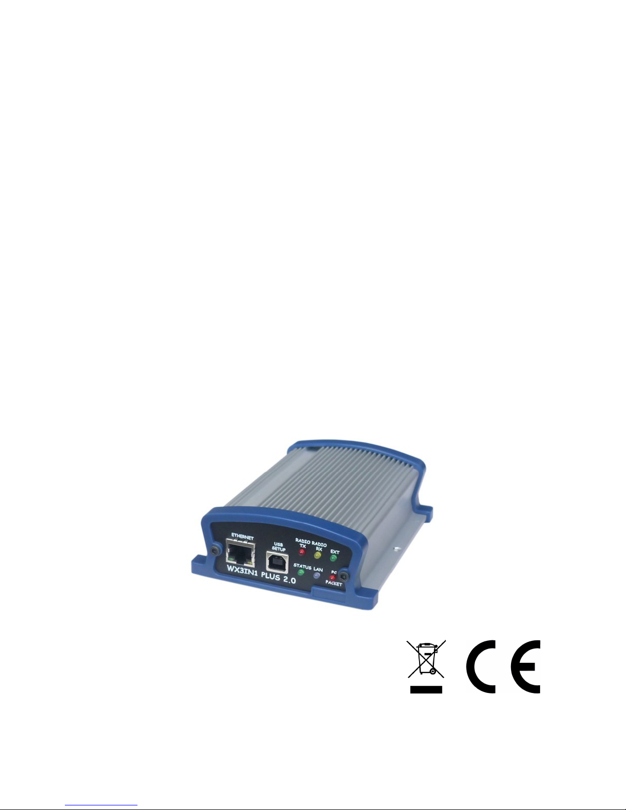
WX3IN1 Plus 2.0 (firmware v1.09)
(manual revision 15 March 2016)
APRS 1200 BAUD/AFSK AND 9600/GMSK PACKET DECODING/ENCODING
APRS STATION AND STANDALONE DIGIPEATER
APRS/RF TO APRS-IS IGATE
APRS-IS TO APRS/RF FORWARDING
GPS MODULE SUPPORT FOR CURRENT POSITION BEACONING
KISS PROTOCOL TNC VIA EXTERNAL BLUETOOTH INTERFACE
KISS PACKET OUTPUT AND APRS-IS PROTOCOL SIMPLE TCP/IP SERVER
WEATHER STATION SUPPORT
WEATHERUNDERGROUND SERVICE REPORTING
EXTERNAL TELEMETRY MODULE SUPPORT
INPUT VOLTAGE MEASUREMENT
DIGITAL THERMOMETER INPUT
WWW INTERFACE FOR ADMINISTRATION
TELNET INTERFACE FOR MONITORING
NTP SUPPORT FOR TIME SYNCHRONIZATION
REMOTE FIRMWARE UPDATE VIA TFTP
Instruction manual
Configuration software manual
Designer: Mateusz Płociński SQ3PLX
Producer: Microsat
info@microsat.com.pl
1

Table of Contents
1. Technical parameters..............................................................................4
2. Device features.....................................................................................5
2.1. APRS station....................................................................................5
2.2. APRS digipeater...............................................................................5
2.3. RF -> APRS-IS forwarding (I-Gate)..........................................................5
2.4. APRS-IS -> RF forwarding.....................................................................5
2.5. GPS module support..........................................................................5
2.6. Bluetooth interface support and a KISS TNC operation.................................6
2.7. KISS via TCP/IP packet output..............................................................6
2.9. Weather station support.....................................................................6
2.10. Weather Underground service support...................................................6
2.11. Telemetry reports...........................................................................7
2.12. WXTelemetry module support (analog channels).......................................7
2.13. WXBits telemetry module support (digital inputs/outputs)...........................7
2.14. RTC clock and NTP time synchronization support......................................7
2.15. Firmware and configuration updates.....................................................7
2.16. Remote WWW access........................................................................8
2.17. Remote telnet access.......................................................................8
3. Connectors and device status leds...............................................................9
3.1. Front panel.....................................................................................9
3.2. Rear panel....................................................................................10
4. Radio connector...................................................................................11
4.1. Audio output level regulation..............................................................11
4.2. Audio input level.............................................................................11
4.3. High-pass filter jumper.....................................................................12
5. External devices connectors.....................................................................13
5.1. RS-232 serial ports connector.............................................................13
5.2. RS-485 connector............................................................................13
5.3. Thermometer connector....................................................................13
6. Connecting GPS receiver.........................................................................15
7. Connecting the weather station................................................................16
7.1. LaCrosse/Technoline WS-2300, WS-2350 stations......................................16
7.2. Peet Bros Ultimeter stations...............................................................16
7.3. Davis Vantage stations......................................................................16
8. Connecting Bluetooth interface.................................................................18
9. Connecting to PC..................................................................................19
10. Description of configuration software........................................................20
10.1. Reading configuration from the device.................................................20
10.2. Writing configuration to the device.....................................................20
10.3. Firmware update...........................................................................20
10.4. Configuration import/export.............................................................20
10.5. Radio Tab....................................................................................21
10.6. Digipeater Tab..............................................................................22
10.6.1. Digipeater / Common settings......................................................23
10.6.2. Digipeater / PATH filter rule........................................................23
10.6.3. Digipeater / PATH filter areas......................................................24
10.6.4. Digipeater / Callsign filter rules...................................................26
10.7. Beacons Tab.................................................................................26
2

10.8. Network Tab.................................................................................28
10.9. APRS-IS gateway Tab.......................................................................29
10.9.1. APRS-IS gateway / APRS-IS server Tab.............................................30
10.9.2. APRS-IS gateway / APRS-IS (common) Tab........................................31
10.9.3. APRS-IS gateway / RF->APRS-IS.....................................................31
10.9.4. APRS-IS gateway / APRS-IS->RF (messages).......................................32
10.9.5. APRS-IS gateway / APRS-IS->RF (non-messages).................................33
10.10. RTC/NTP Tab...............................................................................35
10.11. Remote access Tab........................................................................35
10.11.1. Remote access / WWW.............................................................36
10.11.2. Remote access / Telnet............................................................37
10.11.3. Remote access / KISS via TCP/IP.................................................38
10.11.4. Remote access / APRS-IS simple server..........................................38
10.12. Telemetry reports Tab....................................................................39
10.12.1. Telemetry reports / Report settings.............................................39
10.12.2. Telemetry reports / Analog channels............................................40
10.12.3. Telemetry reports / Digital channels............................................41
10.12.4. Telemetry reports / WXBits outputs.............................................42
10.13. Weather reports Tab......................................................................43
10.13.1. Weather reports / Weather beacon..............................................43
10.13.2. Weather reports / Weather Underground.......................................44
10.14. External interfaces Tab..................................................................45
10.14.1. External interfaces / RS-232 ports...............................................45
10.14.2. External interfaces / RS-485 ports...............................................46
10.14.3. External interfaces / Thermometer port........................................46
10.14.4. External interfaces / Weather station...........................................47
10.14.5. External interfaces / GPS receiver...............................................47
10.14.6. External interfaces / KISS.........................................................48
10.14.7. External interfaces / RS-131 gamma monitor..................................48
11. Telnet interface..................................................................................49
11.1. Telnet client software.....................................................................49
11.2. Telnet commands...........................................................................49
12. Remote firmware update via TFTP............................................................51
13. Troubleshotting...................................................................................52
3

1. Technical parameters
Dimensions 126x99x43 mm
Weight 270g
Supply voltage 12VDC typ. (9 - 16VDC)
Power consumption 150mA
Operation temperature -20°C / +70°C
Humidity 95% max.
Ethernet 10/100 Base-T
Power connector 5.5/2.1mm connector
Telemetry module connector Terminal block, RS-485 2-wire standard
Thermometer connector Terminal block, DS18B20/DS18S20 standard
Serial ports connector Mini DIN 6-pin, 2 ports, RS-232 standard
Radio connector Mini DIN 6-pin
PC connector USB-B (printer cable type)
4

2. Device features
2.1. APRS station
WX3in1 Plus 2.0 allows you to generate APRS data packets with information field
defined by user and send them in a specified interval. In this way, it is possible to send
beacons, objects, weather and telemetry data.
2.2. APRS digipeater
The main purpose of the device is receiving and sending APRS data packets via
amateur radio transceiver. WX3in1 Plus 2.0 is capable of receiving an APRS packet,
decoding the sender, recipent, path and information field. Then actions are performed
in accordance with the options configured by user:
• Packet is digipeated via the APRS network,
• Packet is sent to the APRS-IS server,
• Packet is ignored if it was corrupted.
Device firmware implements the following mechanisms:
• Checksum Verification - packets with errors are ignored,
• Anti-flood - packets repeated in a short time interval are not forwarded,
• Path checking - a decision whether to digipeat a packet or not is made using a
filter stored in configuration data of the device. User defines whether to forward
WIDE1-1, WIDEn-N, SPn-N, or local path packets and the maximum value of N (so
called New-N paradigm),
• Area filter – allows to digipeat packets only from stations located within a defined
radius from the device, within a defined radius from a point on the map or within
a rectangle defined by north-western and south-eastern point on the map,
• Callsign filter - a simple callsign filter allows you to add stations to black list
(these stations will be ignored) or white list (only these stations will be
digipeated).
2.3. RF -> APRS-IS forwarding (I-Gate)
WX3in1 Plus 2.0 allows you to connect to APRS-IS server network. After logging to
selected server, it is possible to gate data received from the APRS radio network. All
packets with correct format and checksum are forwarded to APRS-IS.
2.4. APRS-IS -> RF forwarding
WX3in1 Plus 2.0 allows you to receive packets from APRS-IS server. Then a
decision is made whether to gate a packet to RF or not. It is possible to forward
different types of packets based on a filter defined in device configuration. APRS
message packets can be forwarded to stations which were heard on RF within limited
number of digi-hops (local RF), and they are repeated up to 3 times in case of no ACK
packet received from message recipient.
2.5. GPS module support
WX3in1 Plus 2.0 allows you to connect an optional GPS receiver module to report
5

current position in APRS and APRS-IS beacons. Therefore it is possible to use it with a
moving station and display a real-time position on the map.
2.6. Bluetooth interface support and a KISS TNC operation
Firmware version 1.08 adds a functionality of a KISS protocol TNC allowing to
forward received packets via optional Bluetooth interface connection to an external
device (e.g. Android smartphone). It is also possible to receive packets from Bluetooth
and send them to RF. Thereby it is now possible to use the device as a Bluetooth TNC.
Tests were made with APRSDroid 1.3.0 giving a nice ability to show received
packets on the application map and allowing to send packets from mobile phone to RF.
2.7. KISS via TCP/IP packet output
This feature allows any networked device to connect to WX3in1 Plus 2.0 TCP/IP
port and receive packets in KISS format without a need to use of a Bluetooth module. At
the time of writing of this manual revision (firmware v1.09) KISS via TCP/IP is only one
direction (RF TCP/IP). KISS via TCP/IP was successfully tested with APRSDroid 1.3.0.→
2.8. APRS-IS simple server
APRS-IS simple server allows any networked device to connect to WX3in1 Plus 2.0
TCP/IP port and receive packets in APRS-IS format. APRS-IS simple server connection is
bi-directional (RF TCP/IP, TCP/IP RF) and it also allows to exchange packets with→ →
currently connected APRS-IS T2 server. This feature allows third-party software to use
WX3in1 Plus 2.0 as a gateway between network and radio channel.
2.9. Weather station support
WX3in1 Plus 2.0 allows you to receive weather information from weather stations
using RS-232 cable. Data is then encoded into the APRS packet and may be sent to
APRS/APRS-IS network at specified intervals.
Supported weather stations:
• LaCrosse/Technoline WS-2300,
• LaCrosse/Technoline WS-2350,
• Peet Bros Ultimeter 100,
• Peet Bros Ultimeter 800,
• Peet Bros Ultimeter 2000,
• Peet Bros Ultimeter 2100,
• Davis Vantage Pro (with RS232 datalogger),
• Davis Vantage Pro2 (with RS232 datalogger),
• Davis Vantage Pro Plus (with RS232 datalogger),
• Davis Vantage Pro2 Plus (with RS232 datalogger),
2.10. Weather Underground service support
Weather Underground is one of the biggest weather services available on the web.
It allows you to create an account for your weather station and send weather reports
which are stored in their database. Data is then available for view in form of graphs,
tables or a simple web page applet showing current conditions in your location. Anyone
6

can send his weather data using a simple internet protocol.
In WX3in1 Plus 2.0 you can configure your Weather Underground account name,
password and send weather data in preconfigured time intervals. You can also send your
weather data in “rapid fire” mode every 5 seconds and see your weather changes
realtime using Weather Underground web page applet.
2.11. Telemetry reports
Device allows you to send telemetry reports to APRS/APRS-IS network. Possible
telemetry channels are:
• input voltage,
• received APRS packets in 1 hour or 10 minutes window,
• digipeated APRS packets in 1 hour or 10 minutes window,
• packet decoding efficiency in 1 hour window or in the whole range from device
power-up,
• temperature from optional DS18B20 digital thermometer connected on the rear
panel of the device.
2.12. WXTelemetry module support (analog channels)
You can get more telemetry report options when using external WXTelemetry
module. With WXTelemetry module you can measure and send following values:
• two current measurement inputs,
• two voltage measurement inputs,
• DS18B20 digital thermometer input.
2.13. WXBits telemetry module support (digital inputs/outputs)
You can use an additional WXBits module for reporting of digital input channels
and administration of output channels. WXBits is a module which includes:
• 4 optocoupler digital inputs,
• 4 mosfet transistor open-collector outputs.
States of both inputs and outputs can be reported in APRS telemetry reports and outputs
can also be controlled with WX3in1 Plus 2.0 telnet interface.
2.14. RTC clock and NTP time synchronization support
With WX3in1 Plus 2.0 you always have the current date and time thanks to NTP
support. Device connects to a defined NTP server every few minutes and checks for the
current time. Local passage of time is handled by on-board RTC clock with a battery.
2.15. Firmware and configuration updates
In WX3in1 Plus 2.0 you can do all firmware and configuration updates over an USB
cable connection from your PC using a simple Configurator application. If your device is
located in a remote location, you can update firmware and configuration via the
internet using TFTP protocol.
7

2.16. Remote WWW access
With WX3in1 Plus 2.0 device it is possible to configure and view device statistics
remotely via web browser.
2.17. Remote telnet access
You can connect to your WX3in1 Plus 2.0 device with a telnet client. Telnet
connection allows you to check all device operation messages, read device statistics,
send some test packets useful during installation, control digital outputs of WXBits
module, and much more.
8
3. Connectors and device status leds
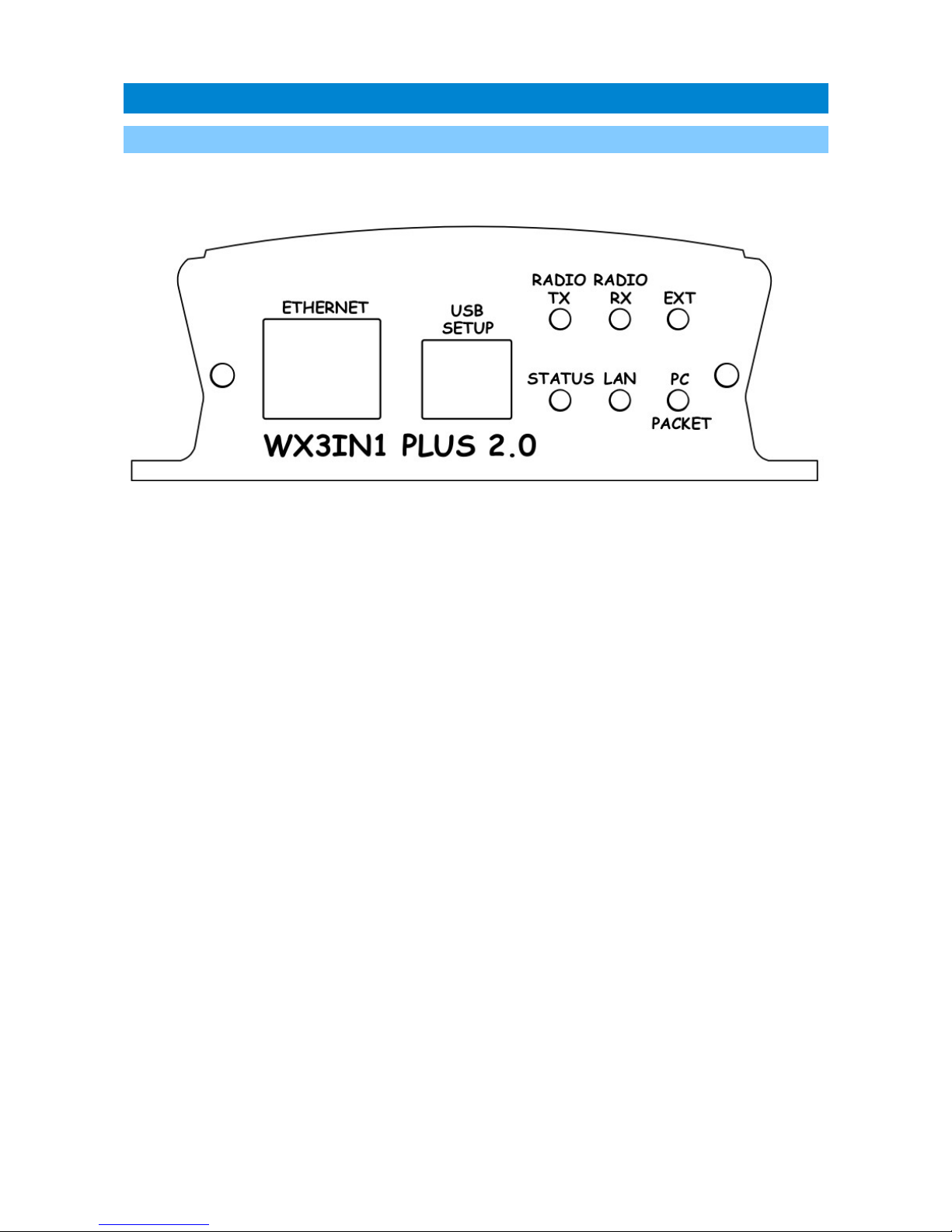
3.1. Front panel
There are 6 leds on the front panel which inform about the status of device
operation. The following image shows the location of front panel LEDs and connectors.
Leds:
• Radio TX - The red led lights during transmission - the device sends an APRS data
packet,
• Radio RX - Yellow led illuminates when receiving a signal from the radio
(indicates the channel is busy),
• Ext - Green led indicates proper communication with external device, it blinks
after reception of:
• correct weather data from weather station,
• GPS NMEA sentence with fixed position,
• temperature from external sensor,
• telemetry data from WXTelemetry/WXBits.
• Status - Green led indicates the status of the device (led lights up regularly every
3 seconds, indicating correct operation),
• Lan TX - Blue led illuminates when sending TCP/IP packet to the Ethernet,
• PC/Packet – This red led has two purposes. In PC configuration mode it blinks
regularly and in device working mode it blinks when there is a proper packet
received from the radio.
Connectors:
• Ethernet - RJ45 (ethernet network connection),
• USB - a USB socket-B (printer type), used to connect to a computer for
configuration and firmware update,
9
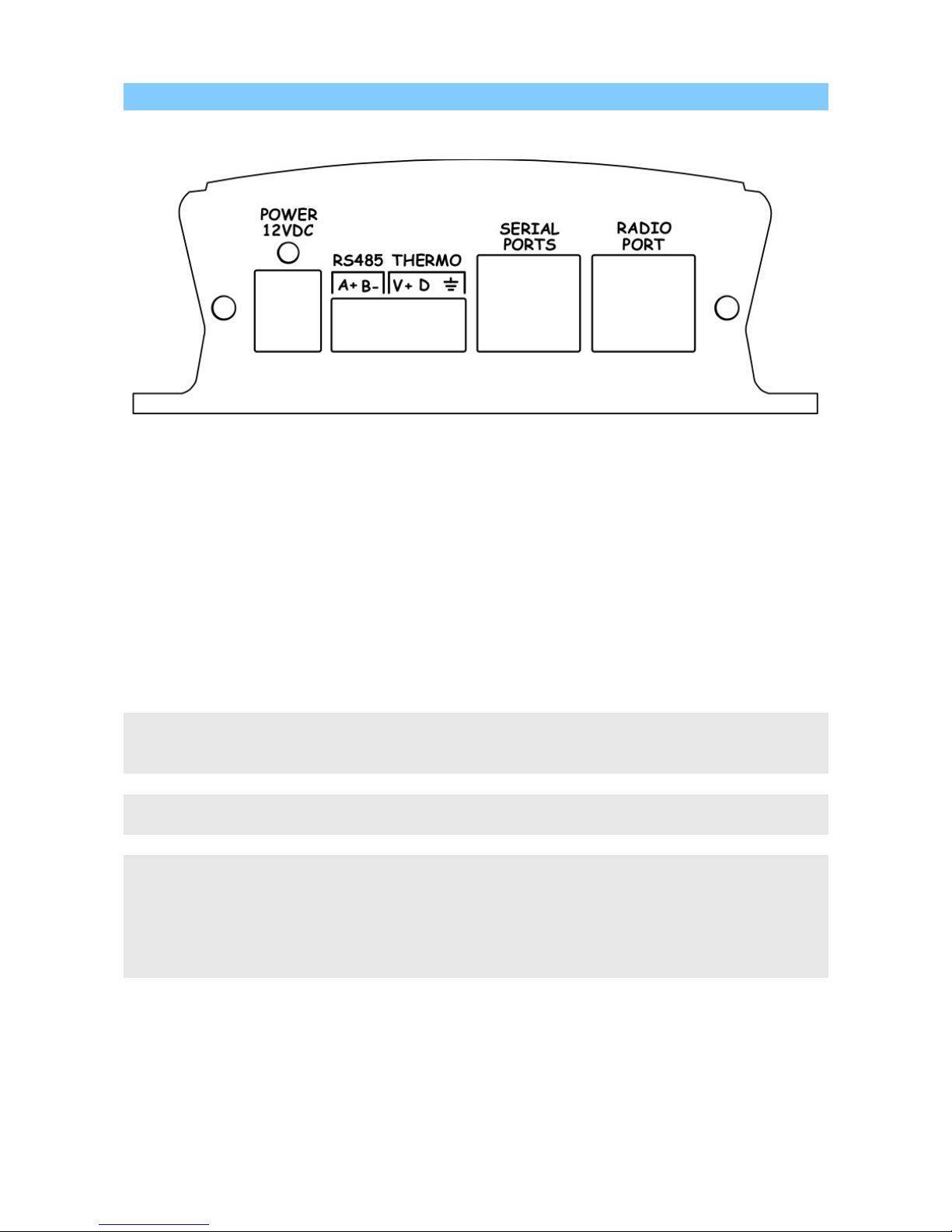
3.2. Rear panel
The following image shows the location of rear panel LEDs and connectors.
Leds:
• Power led - The red led above the power connector indicates that the power is
applied.
Connectors:
• Power – 5.5/2.1 type power connector (center pin is a power supply plus),
• RS485 – terminal block connector for serial port for WXTelemetry/WXBits,
• Thermo – terminal block connector for DS18B20/DS18S20 connector,
• Serial ports – Mini DIN 6-pin connector for dual serial ports and 5V voltage output
(the same pinout as PLXDigi/PLXTracker),
• Radio connector - Mini DIN 6-pin connector for radio audio in, audio out, GND,
and PTT.
Warning: PTT switch is operated using MOSFET transistor. Please make sure that there
are no short-circuits in radio cable. Shorting PTT output do positive voltage can result is
transistor damage.
Serial port 5V voltage output is protected with diode and polymer fuse. Maximum output
current should not be above 100mA.
If you are going to use both WXTelemetry and WXBits external telemetry modules, you
should connect them in a chained style: A+ and B- pair go from WX3in1 to first telemetry
module, and then from first telemetry module to the second one. From a schematic
point of view, both modules must be connected in parallel (A+ from WX3in1 goes to A+ of
the first module, and then to A+ of the second, similarly with B-). Never connect A+ to
B-.
10
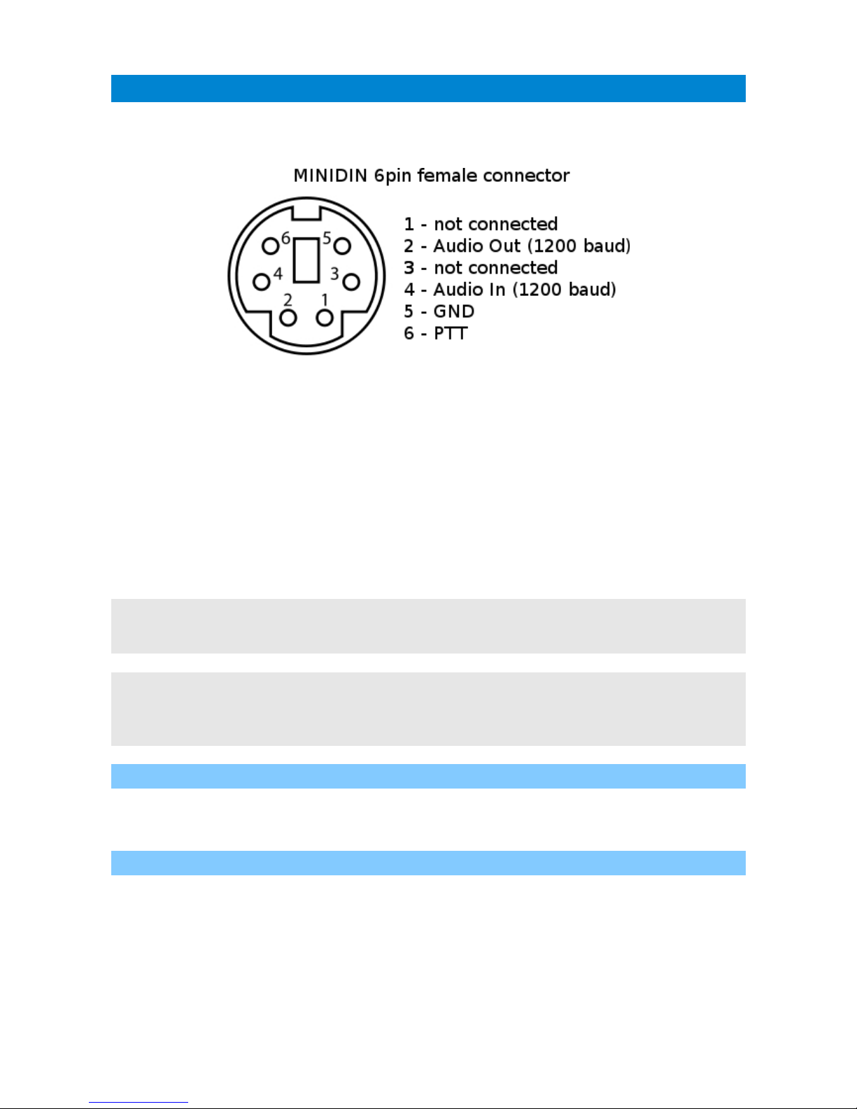
4. Radio connector
Radio MINI DIN 6pin connector is placed on the rear panel of WX3in1 Plus 2.0.
Pinout of this connector is described in the following figure.
Connector pinout description:
1. not connected,
2. APRS audio output from the device to the microphone input of the radio. This
output also acts as a PTT by shorting pin to ground through a 2k2 resistor - an
option for portable radios that do not have a separate PTT input (selectable in
configuration software, 2k2 resistor is built-in),
3. not connected,
4. APRS audio input from radio to WX3in1,
5. Ground pin,
6. PTT output - if the external PTT output is selected in device configuration, this
pin is shorted to ground while broadcasting.
Warning: PTT switch is operated using MOSFET transistor. Please make sure that there
are no short-circuits in radio cable. Shorting PTT output do positive voltage can result is
transistor damage.
For handheld radios which use 2k2 resistor on microphone input line you don't need to
use any external resistor or external PTT (pin 6) output. Connect pins: 2 (audio output),
4 (audio input), 5 (ground) and set “PTT:” to “2k2 resistor” in device configuration. 2k2
resistor is located inside of the device.
4.1. Audio output level regulation
In WX3in1 Plus 2.0, audio output is configured in software. Possible output level
ranges from 40mV to 900mV with output impedance of around 500 Ohm.
4.2. Audio input level
In WX3in1 Plus 2.0 audio input level amplifier is configured in software. Default
amplifier setting is configured to +0db and with this amplifier setting device should be
able to decode packets with input levels as low as 25mV p-p and as high as 1V p-p. In
case of low-level signals it is recommended to increase input amplifier settings for best
decoding efficiency.
11

4.3. High-pass filter jumper
There is only one jumper on a PCB inside of the device (located behind radio port
connector). It should be open for proper operation of 1200/AFSK baudrate APRS
decoding. Of you are going to use 9600/GMSK packet decoding, then you should close
this jumper for flat frequency response down to DC). Closing this jumper may lead to
poor 1200/AFSK baudate decoding for some radios.
12

5. External devices connectors
5.1. RS-232 serial ports connector
In WX3in1 Plus 2.0 the MINI DIN 6pin female connector is used for RS-232 serial
ports and 5V voltage output.
MINI DIN 6pin connector pins description:
• Pin 6 – RS-232 Port 1 RXD (default: weather station),
• Pin 4 – RS-232 Port 2 TXD (default: GPS module),
• Pin 2 – GND,
• Pin 1 – 5V output, do not short-circuit, max. current 100mA,
• Pin 3 – RS-232 Port 1 TXD (default: weather station),
• Pin 5 – RS-232 Port 2 RXD (default: GPS module).
Serial port 5V voltage output is protected with diode and polymer fuse. Maximum output
current should not be above 100mA.
If Bluetooth interface support is enabled in device configuration, then RS-232 Port 2 is
reserved for Bluetooth connection status check. In this case RS-232 Port 1 works with
baudrate of 9600 for proper Bluetooth interface communication.
5.2. RS-485 connector
RS-485 connector is intended to be used with WXTelemetry and WXBits external
modules.
If you are going to use both WXTelemetry and WXBits external telemetry modules, you
should connect them in a chained style: A+ and B- pair go from WX3in1 to first telemetry
module, and then from first telemetry module to the second one. From a schematic
point of view, both modules must be connected in parallel (A+ from WX3in1 goes to A+ of
the first module, and then to A+ of the second, similarly with B-). Never connect A+ to
B-.
5.3. Thermometer connector
Thermometer connector is intended to be used with DS18B20 or DS18S20 digital
thermometer. It consists of:
• 5V voltage output (connect to VDD of thermometer),
• DATA line (connect to DQ of thermometer),
13

• GND (connect to GND of thermometer).
14
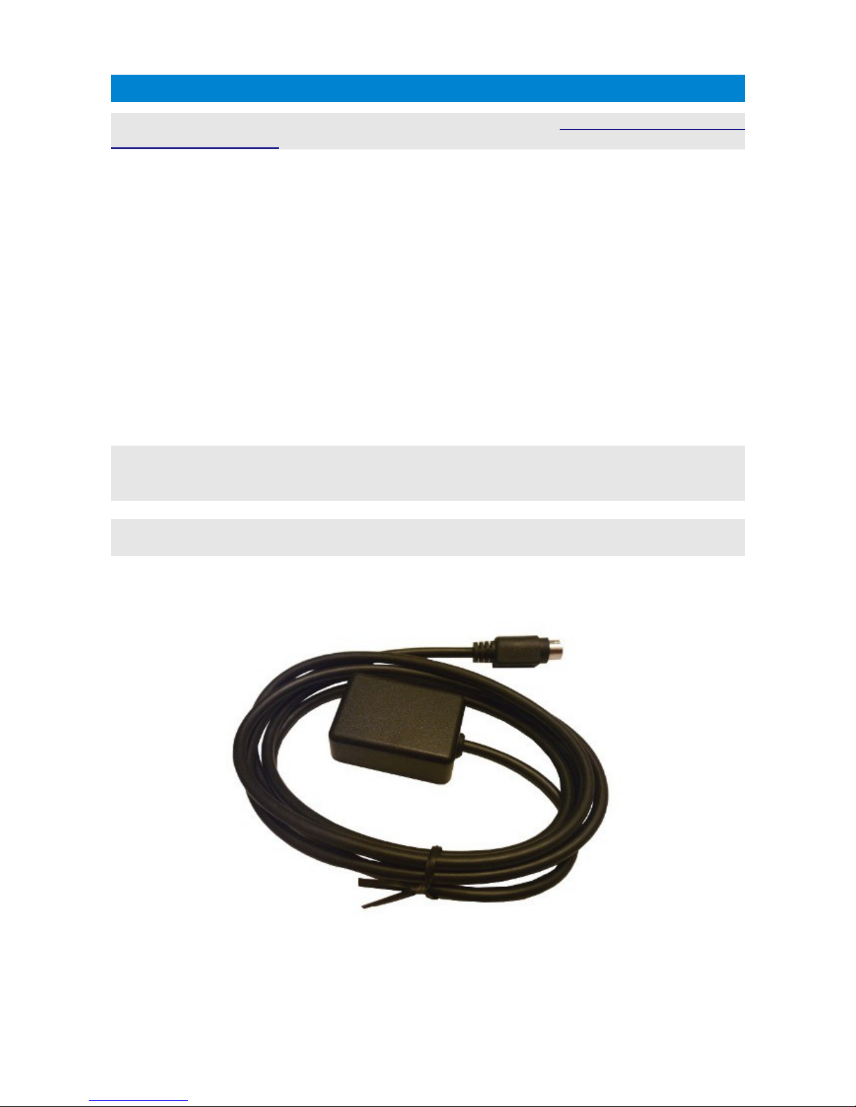
6. Connecting GPS receiver
WX3in1 Plus 2.0 serial port connector is compatible with our “GPS-RS232/Microsat - GPS
receiver (minidin 6-pin)”. It can be connected directly without any additional adapters.
You can use any GPS receiver with compatible pinout and current consumption
below 100mA (below 60mA is recommended, as higher currents may cause a voltage drop
below 5V on protection diode and polymer fuse which can prevent proper operation of
GPS receiver).
If you are going to use a GPS receiver from other manufacturer, it must provide
GPRMC and GPGGA NMEA sentences for proper operation. Most modern GPS receivers
and modules support these sentences. Serial port baudate is selectable in WX3in1 Plus
2.0 configuration.
Following lines of WX3in1 Plus 2.0 serial port are used for GPS data reception:
• Pin 5 – RS-232 Port 2 RXD (data reception).
• Pin 2 – GROUND.
Communication with GPS receiver is uni-directional (only data reception), so RS-
232 Port 2 TXD is not used (although it is connected in some types of our pre-made
cables).
If you are going to use third-party GPS receiver, please make sure to power it with
correct voltage (our GPS-RS232/Microsat receiver accepts input voltage up to 16VDC,
most others accept only 5V +/- 10%) and make sure that it uses RS-232 voltage levels.
If you want to connect both GPS receiver and weather station to WX3in1 Plus 2.0, please
check more details in “Connecting the weather station” chapter.
15

7. Connecting the weather station
7.1. LaCrosse/Technoline WS-2300, WS-2350 stations
The only difference between WS-2300 and WS-2350 weather stations is that
manufacturer has made an external USB to RS232 adapter, which is not used in case of
WX3in1 Plus 2.0.
WS-23XX weather stations require a bit exotic connection method. There is no
GND connection and both positive and negative 5V voltages are necessary for interfacing
(-5V on DTR pin, and +5V on RTS pin). To connect WS-23XX weather station, we need to
use WX3in1 Port 2 TXD as negative polarization voltage source on DTR pin.
To connect WS-2300 or WS-2350 station to WX3in1 Plus 2.0 you will need to use:
- “CAB02 - WX3in1 Plus 2.0/PLXDigi/PLXTracker serial interface cable (for WS-23XX)” – in
case you don't want to connect also GPS receiver,
- ”CAB28 - WX3in1 Plus 2.0 serial interface cable (for WS-23XX + GPS)” – if you want to
connect both weather station and GPS receiver.
Schematics for both cables are available on our webpage.
7.2. Peet Bros Ultimeter stations
Peet Bros Ultimeter weather stations use a standard RS-232 serial port interface
with TXD, RXD and GND. Other serial lines are not used. Stations must then be manually
switched to "data logger" mode. According to the manufacturer's instructions, you should
press CLEAR + WIND SPEED buttons for 3 seconds to activate the "data logger".
Starting with firmware v1.09 it is also possible to use “complete record mode”
which is properly decoded by WX3in1 Plus 2.0.
To connect Peet Bros Ultimeter station to WX3in1 Plus 2.0 you will need to use:
- ”CAB29 - WX3in1 Plus 2.0 serial interface cable (for Davis, PeetBros)” – in case you
don't want to connect also GPS receiver,
- ”CAB27 - WX3in1 Plus 2.0 serial interface cable (for Davis, PeetBros + GPS)” – if you
want to connect both weather station and GPS receiver.
Schematics for both cables are available on our webpage.
7.3. Davis Vantage stations
Davis Vantage weather stations use a standard RS-232 serial port interface with
TXD, RXD and GND. Fourth wire is connected to DCD, DTR, and DSR inside original DB-9
connector but it shouldn't be used on WX3in1 Plus 2.0 side.
To connect WX3in1 Plus 2.0 to Davis weather stations you need to use an
additional RS-232 “datalogger” interface available from the manufacturer. Device part
number is 06510SER.
Davis stations datalogger interface comes in two kinds: “standard” datalogger or “APRS”
datalogger. According to my current knowledge, both types work fine with WX3in1 Plus
2.0 (it doesn't use an “APRS” feature of datalogger but “APRS” datalogger has also the
same communication options like “standard” one).
16
 Loading...