

Microsat APRS Voyager Instruction Manual
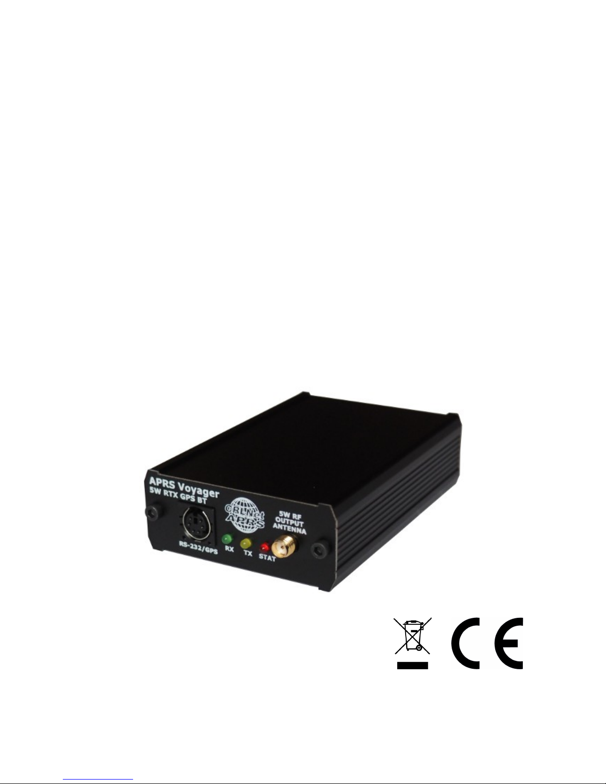
APRS Voyager (firmware v1.03)
(manual revision 06 February 2017)
BUILT-IN 38.5 DBM / 7 WATT TRANSCEIVER
MIC-E/BASE-91/PLAIN TEXT POSITION REPORTING
BUILT-IN BLUETOOTH INTERFACE
SIMPLE ALIAS-BASED APRS PACKET DIGIPEATER
WEATHER STATION SUPPORT
EXTERNAL TELEMETRY MODULE SUPPORT
DIGITAL THERMOMETER SUPPORT
INPUT VOLTAGE MEASUREMENT
SERIAL CONSOLE FOR ADMINISTRATION
EASY USB-HID PROGRAMMING
Instruction manual
Configuration software manual
Designer: Mateusz Płociński SQ3PLX
Producer: Microsat
info@microsat.com.pl
1

Table of Contents
1. Technical parameters..............................................................................3
2. Device features.....................................................................................4
2.1. Built-in 38.5 dbm / 7 watt transceiver....................................................4
2.2. Mic-E/Base-91/Plain text position reporting.............................................4
2.3. Built-in Bluetooth interface.................................................................4
2.4. Simple alias-based APRS packet digipeater...............................................4
2.5. Weather station support.....................................................................5
2.6. External telemetry module support........................................................5
2.7. Digital thermometer support................................................................5
3. Connectors and device status leds...............................................................6
3.1. Front panel.....................................................................................6
3.2. Rear panel......................................................................................7
4. RS-485 / thermometer connector................................................................8
4.1. RS-485 connection............................................................................8
4.2. Thermometer connector.....................................................................8
5. Serial port connector..............................................................................9
6. Connecting the weather station................................................................10
6.1. LaCrosse/Technoline WS-2300, WS-2350 stations......................................10
6.2. Peet Bros Ultimeter stations...............................................................10
6.3. Davis Vantage stations......................................................................10
7. Connecting to PC..................................................................................11
8. Description of configuration software.........................................................12
8.1. Reading configuration from the device..................................................12
8.2. Writing configuration to the device......................................................12
8.3. Firmware update............................................................................12
8.4. Configuration import/export..............................................................12
8.5. Radio Tab......................................................................................13
8.6. Position reports Tab.........................................................................14
8.7. Digipeater Tab................................................................................16
8.7.1 Digipeater / Common settings Tab...................................................16
8.7.2 Digipeater / Simple aliases Tab.......................................................17
8.8. Beacons Tab..................................................................................18
8.9. Telemetry reports Tab......................................................................19
8.9.1. Telemetry reports / Report settings................................................20
8.9.2. Telemetry reports / Analog channels...............................................21
8.9.3. Telemetry reports / Digital channels...............................................22
8.9.4. Telemetry reports / WXBits outputs................................................22
8.10. Weather reports Tab.......................................................................23
8.11. External interfaces Tab....................................................................24
8.11.1. External interfaces / Serial ports..................................................24
8.11.2. External interfaces / Bluetooth....................................................25
8.11.3. External interfaces / RS-485 port..................................................26
8.11.4. External interfaces / Weather station............................................27
8.11.5. External interfaces / Serial console...............................................27
8.11.6. External interfaces / GPS receiver................................................28
8.11.7. External interfaces / KISS...........................................................29
8.12. Test tone.....................................................................................30
9. Bluetooth connection with APRSDroid.........................................................31
2

1. Technical parameters
Mechanical:
Dimensions (without connectors) 100x69x28 mm
Weight 150 g
Housing material Aluminium
Connectors / interfaces:
RF connector SMA female
Power connector Round 5.5/2.1mm (with plus at center)
Telemetry / thermometer connector Terminal with screws (shared)
Serial port connector Mini DIN 6-pin female (1 serial port)
Bluetooth module HC-05 module, Bluetooth v2.0, Class 2 with
integrated antenna
Environment:
Operation temperature -20°C / +50°C
Humidity 95% max.
Electrical:
Supply voltage 12-14 VDC typ. (14.4 VDC max.)
Power consumption (at 13VDC/5W) 80 mA (RX),
1150 mA (TX)
Power consumption (at 13VDC/7W) 80 mA (RX),
1380 mA (TX)
RF transmitter / receiver
Antenna impedance 50 Ohm
Frequency range 144 - 146 MHz (wider range not tested)
Output power 37 dbm / 5 watt
Output filter 5-pole LPF
Maximum transmit time 20 seconds within 60 seconds window (33%
duty cycle)
Squelch (level 1) sensitivity (*) -112 dBm (squelch opens), -114 dBm (squelch
closes)
Proper packet decoding signal level (*) (available soon, needs to be exactly tested)
* tests were made using HP8656B signal generator with packets injected via external
modulation input at 2.5 kHz FM modulation.
3

2. Device features
2.1. Built-in 38.5 dbm / 7 watt transceiver
APRS Voyager incorporates a built-in 38.5dbm / 7 watt transceiver capable of
transmitting and receiving APRS packets. The only thing you need to do is to connect a
proper antenna to SMA connector. Output power is programable between 5 watt and 7
watt.
2.2. Mic-E/Base-91/Plain text position reporting
The main feature for an APRS tracker is position reporting. APRS Voyager allows
you to select between three most common position reporting formats:
• Mic-E – uses both AX.25 destination address and information field for position
report and is the most compact reporting method, giving the shortest packet
length,
• Base-91 – second compressed method oriented to short report packet length,
• Plain text – in this method station position report is sent in human-readable plain
text format,
You can also select between fixed time interval reporting which means that packets are
sent every X number of seconds, and SmartBeaconing. SmartBeaconing is an algorithm
which sends position reports with intervals dependent on speed and course, allowing for
more accurate reporting especially in urban area. SmartBeaconing algorithm was first
developed by Tony Arnerich KD7TA and Steve Bragg KA9MVA and now it is widely used by
most APRS tracker devices.
2.3. Built-in Bluetooth interface
APRS Voyager integrates a built-in Bluetooth interface which can work in one of
selectable modes:
• Serial console – similar to RS-232 serial console known from PLXTracker or
PLXDigi, it outputs debuging information for device operation.
• KISS – allows to exchange packets with your laptop, tablet or smartphone with
APRS software installed. This feature works great with APRSDroid available for
Android phones and allows to plot received stations on a map. APRSDroid allows
also to send and receive messages, beacons and SmartBeaconing position via APRS
Voyager.
• GPS passthrough – if you have a GPS receiver connected to APRS Voyager RS-232
serial port, then you can forward NMEA stream to any other device using
Bluetooth interface.
2.4. Simple alias-based APRS packet digipeater
With APRS Voyager you can do a simple alias-based APRS packet digipeating.
Generally APRS tracker units should not be used as a full-featured digipeaters but with
alias-based digipeater feature you can digipeat WIDE1-1 packets sent by other mobiles
increasing their chance of reaching an I-Gate.
4

2.5. Weather station support
APRS Voyager allows you to receive weather data from compatible weather
stations over RS-232 serial interface. Currently supported stations are:
• LaCrosse/Technoline WS-2300,
• LaCrosse/Technoline WS-2350,
• Peet Bros Ultimeter 100,
• Peet Bros Ultimeter 800,
• Peet Bros Ultimeter 2000,
• Peet Bros Ultimeter 2100,
• Davis Vantage Pro (with RS-232 datalogger),
• Davis Vantage Pro2 (with RS-232 datalogger),
• Davis Vantage Pro Plus (with RS-232 datalogger),
• Davis Vantage Pro2 Plus (with RS-232 datalogger),
2.6. External telemetry module support
You can use an additional telemetry module for reporting of voltages and electric
current values of your installation. This is especially useful for monitoring of solar panel
powered systems on remote sites. WXTelemetry module allows you to read 2 voltages, 2
currents and one temperature, then sends these values as APRS telemetry reports to RF.
2.7. Digital thermometer support
If you do not need a telemetry module connected to RS-485 serial bus, then you
can use it for direct connection of DS18B20 or DS18S20 thermometer input. Measured
temperature can then be sent in beacon text or telemetry reports.
5

3. Connectors and device status leds
3.1. Front panel
There are 3 leds on the front panel that show the status of device operation. The
following image shows the location of front panel LEDs and connectors.
Leds:
• Green LED - illuminates when receiving a signal from RF (indicates the channel is
busy),
• Yellow LED - lights during transmission, when the device sends an APRS data
packet,
• Red LED - blinking is dependent on current device state:
• one short blink (0.1 second) per 1.6 seconds – no GPS NMEA sentence
received within last second, GPS disconnected,
• two short blinks (0.1 second each) per 1.6 seconds – GPS NMEA sentence
received but no position fix,
• three short blinks (0.1 second each) per 1.6 seconds – GPS NMEA sentence
received with position fix,
• one long blink (1 second) per 1.6 seconds – APRS packet was properly
received.
Connectors:
• SMA female – 50 Ohm RF antenna connector,
• Mini DIN 6-pin – one RS-232 serial data interface,
Please never power-up the device (via 12V rear panel power input) without proper
antenna connected! RF transistors of every kind of transmitters are sensitive for proper
antenna match and can get damaged when working in unmatched conditions!
APRS Voyager incorporates only one RS-232 serial interface (contrary to PLXTracker or
PLXDigi), located on „RS-232 port 2” pins (port 1 is internally occupied by Bluetooth
interface).
If you wish to use a weather station, serial console, etc., you will need a different set of
serial cables than for PLXTracker or PLXDigi.
6
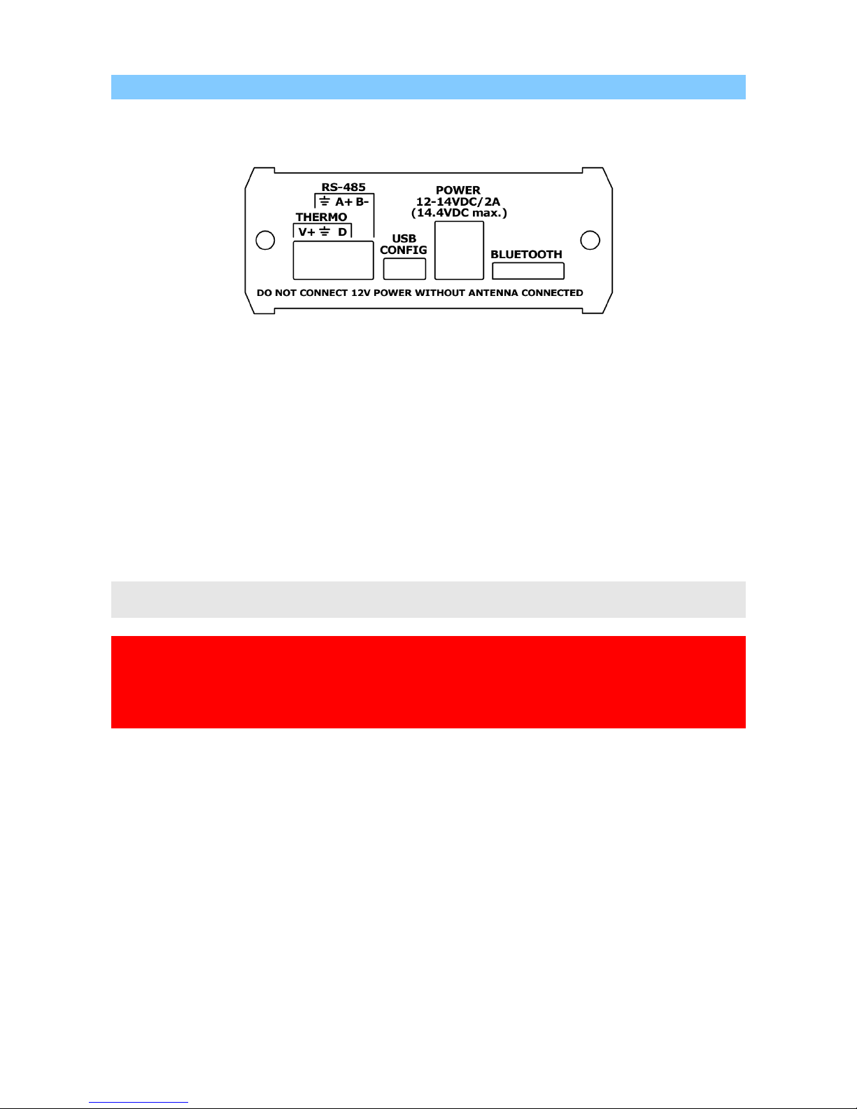
3.2. Rear panel
On rear panel of the device there is a shared RS-485 / thermometer connector
and a round power 5.5/2.1mm connector.
Connectors:
• 4-pin terminal with screws – as shown on the image, you can connect a RS-485
bus using A+ and B- connectors, or DS18B20-type digital thermometer using V+,
GND and DATA connectors (V+ is a weak 5V output for thermometer powering),
• mini USB - a mini USB socket, used to connect to a computer for configuration,
• round 5.5/2.1mm power connector – main power input of the device with
allowed input voltage of around 12V to 14V (with plus at center). A source with
current capacity of at least 2A should be used.
Other:
• Bluetooth antenna – installed outside aluminium case for proper operation. Be
careful not to damage the antenna.
4-pin terminal with screws is shared between RS-485 and digital thermometer. Both
options cannot be used at the same time.
Please do not cross the maximum allowed continous input voltage of 14.4V. RF amplifier
module is specified below 14.4V and may be damaged when powered with higher
voltage.
Device is specified to work correctly when powered with 12V car battery in car system
with properly working alternator.
7
4. RS-485 / thermometer connector
Rear panel RS-485 / thermometer connector options are simple. You can connect
RS-485 extension modules via RS-485 bus or digital thermometer, but not both at the
same time.
4.1. RS-485 connection
For RS-485 connection please connect RS-485 A+ of APRS Voyager to RS-485 A+ of
the module and RS-485 B- of APRS Voyager to RS-485 B- of the module. Both APRS
Voyager and telemetry module must share the same ground potential (should be
powered from the same power source or at least share the ground wire).
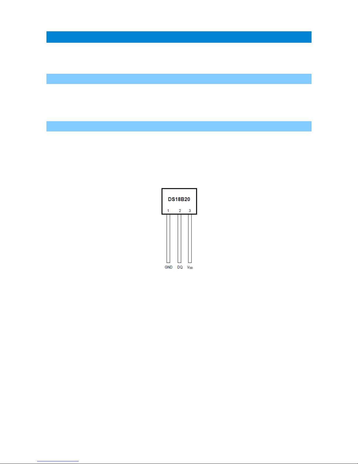
4.2. Thermometer connector
You can connect a DS18B20 or DS18S20 thermometer directly to APRS Voyager rear
panel.
• DS18B20 Vdd goes to APRS Voyager V+ pin,
• DS18B20 GND goes to APRS Voyager ground pin,
• DS18B20 DQ goes to APRS Voyager D pin.
8

5. Serial port connector
In APRS Voyager the MINI DIN 6pin female connector is used for single RS-232
serial port and 5V voltage output.
MINI DIN 6pin connector pins description:
• Pin 6 – not used
• Pin 4 – RS-232 Port 2 TXD,
• Pin 2 – GND,
• Pin 1 – 5V output, do not short-circuit, max. current 100mA,
• Pin 3 – hard-wired to negative voltage for WS-2300/WS-2350 weather station
support,
• Pin 5 – RS-232 Port 2 RXD.
RS-232 Port 2 functions are selectable in software.
APRS Voyager incorporates only one RS-232 serial interface (contrary to PLXTracker or
PLXDigi), located on „RS-232 port 2” pins (port 1 is internally occupied by Bluetooth
interface).
If you wish to use a weather station, serial console, etc., you will need a different set of
serial cables than for PLXTracker or PLXDigi.
9

6. Connecting the weather station
6.1. LaCrosse/Technoline WS-2300, WS-2350 stations
The only difference between WS-2300 and WS-2350 weather stations is that
manufacturer has made an external USB to RS232 adapter, which is not used in case of
APRS Voyager.
WS-23XX weather stations require a bit exotic connection method. There is no
GND connection and both positive and negative 5V voltages are necessary for
interfacing.
To connect WS-2300 or WS-2350 station to APRS Voyager you will need to use:
- “CAB02B - PLXTracker Blue/TRX1W/APRS Voyager serial interface cable (for WS-23XX)”
Schematic for this cable is available on our webpage.
6.2. Peet Bros Ultimeter stations
Peet Bros Ultimeter weather stations use a standard RS-232 serial port interface
with TXD, RXD and GND. Other serial lines are not used. Stations must then be manually
switched to "data logger" mode. According to the manufacturer's instructions, you should
press CLEAR + WIND SPEED buttons for 3 seconds to activate the "data logger".
To connect Peet Bros Ultimeter station to APRS Voyager you will need to use:
- ”CAB29B – PLXTracker Blue/TRX1W/APRS Voyager serial interface cable (for Davis,
PeetBros)”
Schematic for this cable is available on our webpage.
6.3. Davis Vantage stations
Davis Vantage weather stations use a standard RS-232 serial port interface with
TXD, RXD and GND. Fourth wire is connected to DCD, DTR, and DSR inside original DB-9
connector but it shouldn't be used on APRS Voyager side.
To connect APRS Voyager to Davis weather stations you need to use an additional
RS-232 “datalogger” interface available from the manufacturer. Device part number is
06510SER.
Davis stations datalogger interface comes in two kinds: “standard” datalogger or “APRS”
datalogger. According to my current knowledge, both types work fine with APRS Voyager
(it doesn't use an “APRS” feature of datalogger but “APRS” datalogger has also the same
communication options like “standard” one).
To connect Davis Vantage station to APRS Voyager you will need to use:
- ”CAB29B – PLXTracker Blue/TRX1W/APRS Voyager serial interface cable (for Davis,
PeetBros)”
Schematic for this cable is available on our webpage.
10

7. Connecting to PC
Configuration of APRS Voyager can be done via USB interface with APRS Voyager
Configurator software.
APRS Voyager enters into configuration mode only when USB cable is detected while
powering up and it is indicated by Red LED blinking.
To connect to your computer, follow these steps:
• Disconnect APRS Voyager DB-9 cable, device should be unpowered,
• Connect the USB cable from your computer to APRS Voyager, Red LED should start
to blink (device is now powered from USB),
• Now you can use APRS Voyager Configurator for device configuration read/write
or firmware update.
APRS Voyager device appears as USB-HID device in Windows operating system, and
should be detected automatically. Therefore you don't need to install any device drivers
for APRS Voyager.
11
 Loading...