

Page 1

Page 2

Page 3

WedgeLink AT Keyboard Wedge
Copyright © 2015-2017 MicroRidge Systems, Inc.
All rights reserved. No parts of this work may be reproduced in any form or by any means - graphic, electronic, or
mechanical, including photocopying, recording, taping, or information storage and retrieval systems - without the written
permission of the publisher.
Products that are referred to in this document may be either trademarks and/or registered trademarks of the respective
owners. The publisher and the author make no claim to these trademarks.
While every precaution has been taken in the preparation of this document, the publisher and the author assume no
responsibility for errors or omissions, or for damages resulting from the use of information contained in this document or
from the use of programs and source code that may accompany it. In no event shall the publisher and the author be liable
for any loss of profit or any other commercial damage caused or alleged to have been caused directly or indirectly by this
document.
Printed: Tuesday, May 02, 2017 at 8:20 AM in Sunriver, Oregon.
Page 4

Page 5

WedgeLink AT Keyboard Wedge
Table of Contents
IContents
Chapter 1
Chapter 2
Chapter 3
...................................................................................................................................Introduction
...................................................................................................................................Using WedgeLink AT
...................................................................................................................................Startup Initialization
...................................................................................................................................Front Panel
...................................................................................................................................Back Panel
...................................................................................................................................Internal Jumper
...................................................................................................................................Auto Baud Rate Detection
...................................................................................................................................Setup Program
...................................................................................................................................Entering Special Characters
...................................................................................................................................Program Tabs
.......................................................................................................................Home Tab
.......................................................................................................................Read Switch Tab
.......................................................................................................................Character Removal Tab
.......................................................................................................................Character Replacement Tab
.......................................................................................................................Parsing Tabs
.................................................................................................Input Serial Port Parameters
1
5
5
6
8
9
9
13
14
15
15
18
19
20
21
22
Chapter 4
Chapter 5
Chapter 6
Chapter 7
Chapter 8
Chapter 9
...................................................................................................................................Keyboards
...................................................................................................................................ComTestSerial
...................................................................................................................................Accessories
...................................................................................................................................Keyboard Wedges from MicroRidge
...................................................................................................................................Warranty Information
...................................................................................................................................Contact MicroRidge
27
29
31
33
35
37
Copyright © 2015-2017 MicroRidge Systems, Inc.
Page 6

Page 7
WedgeLink AT Keyboard Wedge
1 Introduction
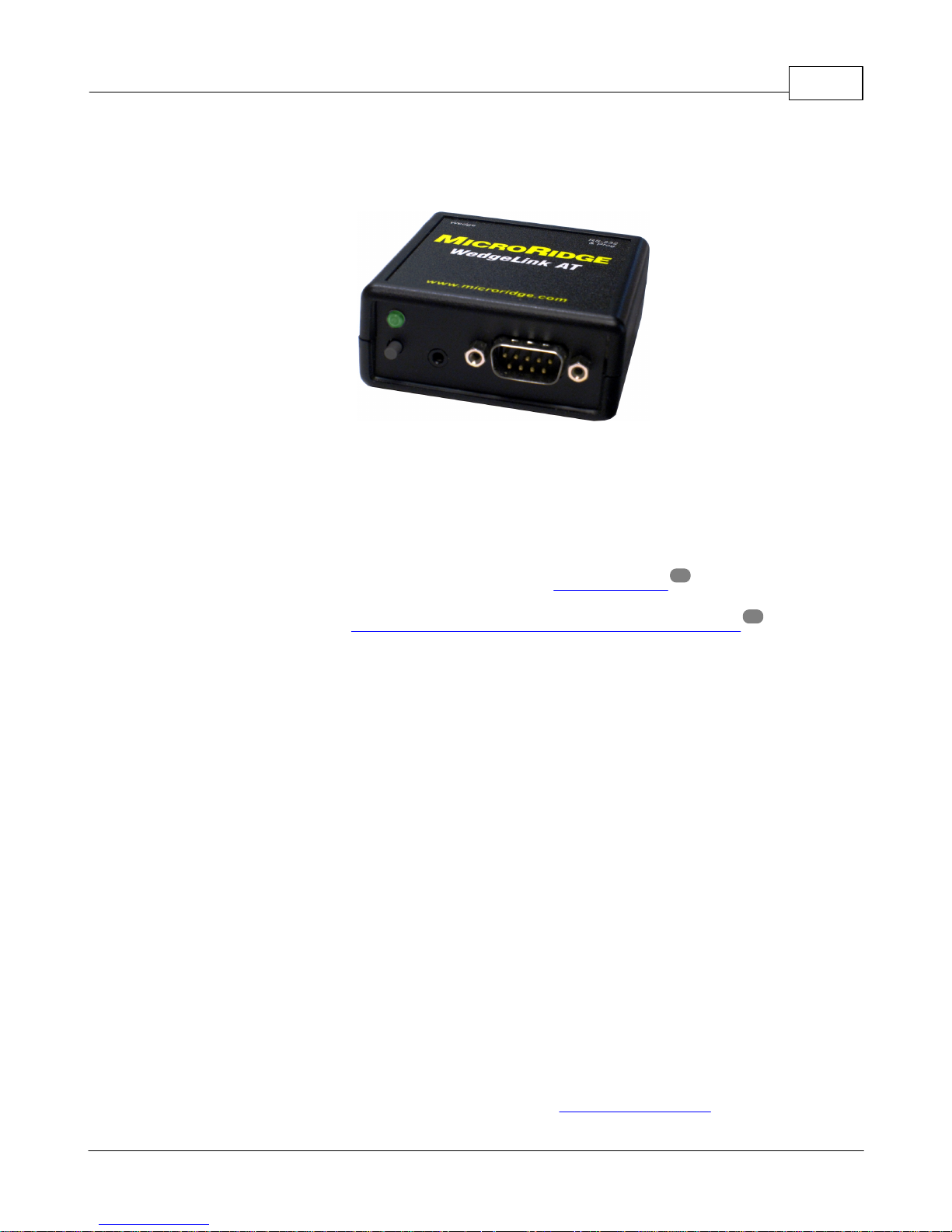
WedgeLink AT is a hardware keyboard wedge that allows you to transfer RS-232 data into any
application that supports keyboard input. WedgeLink AT looks like a standard HID (human
interface device) peripheral to a PC. Other HID peripherals that we are all familiar with are the
USB keyboard and USB mouse. Since WedgeLink AT looks like a standard HID peripheral to
your PC, you do not need to install any drivers for using the wedge feature of WedgeLink AT.
WedgeLink AT is easily configured with the included Setup Program . The Setup Program
communicates with WedgeLink AT via the "RS-232 & Prog" port on the back of WedgeLink AT.
You may need to install the virtual serial port drivers from the WedgeLink AT CD before using
the Setup Program. WedgeLink AT uses a serial to USB IC manufactured by FTDI. If you have
previously installed the FTDI USB drivers, you do not need to reinstall them to use the
WedgeLink AT Setup Program.
Introduction 1
13
5
Features
The key features of WedgeLink AT are as follows:
§ Compact size: 2.61" x 2.61" x 1.10".
§ No driver installation required for the keyboard wedge function (driver installation may be
required for the Setup Program).
§ Supports baud rates from 600 to 57.6K
§ Includes 6' USB cable.
§ Sends commands to your serial device by pressing the push button or remote read switch.
§ Extensive data parsing options.
§ Automatically detects serial baud rate and communication parameters of the connected
serial device (must have a send or print button on the serial device).
§ Serial port Communications Test Program (ComTestSerial) included to assist you in
understanding what is actually being sent from your serial device.
§ Firmware updates available at no charge from the MicroRidge web site.
Copyright © 2015-2017 MicroRidge Systems, Inc.
Page 8

WedgeLink AT Keyboard Wedge2 Introduction
Supported Characters & Data Output
WedgeLink AT supports the standard ASCII characters found on North American keyboards.
When a supported character is received by WedgeLink AT, the character will be processed per
the current setup. If WedgeLink AT receives an unsupported character, the unsupported
character will be discarded.
The characters supported by WedgeLink AT in the Wedge mode (USB cable connected to the
"Wedge" port) include the following:
§ Human readable characters found on the standard keyboard. This includes ASCII
characters from ASCII 32 to ASCII 126 (space, a to z, A to Z, 0 to 9, #, &, etc.).
§ Control characters (less than ASCII 32) backspace, carriage return, escape and tab.
§ Function keys (F1, F2, etc.) that can be added to the input data via the prefix and suffix
features.
The characters supported by WedgeLink AT in the RS-232 mode (USB cable connected to the
"RS-232 & Prog" port) include the following:
§ All 8-bit characters from ASCII 0 to 255 ({\x00} to {\xff}). This includes all control, standard
keyboard and extended characters.
§ Keys such as F1 will be output as a character string. F1 = {F1}, F2 = {F2}, etc.
Parsing and Sending Results via the Keyboard Wedge or Serial Port
Normally WedgeLink AT is used as a keyboard wedge to get data into applications such as
Excel or other database programs. WedgeLink AT also has the ability to capture and parse the
input data and send it to a USB serial port on your PC. It is not uncommon for a serial device to
output a considerable amount of data and all you really want is a number that is contained within
that data. With WedgeLink AT you can extract the number (or data) that you want and send it to
the PC via the keyboard wedge or a serial port connection.
User’s Guide Organization
This User’s Guide covers the WedgeLink AT Setup Program. This document has been
designed for double-sided printing on a color printer. If you print this document single sided,
there will be several blank pages included in the printout.
If you are viewing the PDF version of this User's Guide, you will see page numbers to the right of
the links within the PDF document. For example the number to the right of the Contact
MicroRidge Systems link indicates the actual page number this link is directed to.
37
Copyright © 2015-2017 MicroRidge Systems, Inc.
Page 9

WedgeLink AT Keyboard Wedge
The WedgeLink AT Keyboard Wedge is in compliance with the European Union Directive on the
restricted use of certain hazardous substances (RoHS/RoHS2 Directive). For more information
review the RoHS Declaration of Compliance document on the MicroRidge web.
Introduction 3
Copyright © 2015-2017 MicroRidge Systems, Inc.
Page 10

Page 11

WedgeLink AT Keyboard Wedge
2 Using WedgeLink AT
The WedgeLink AT Keyboard Wedge has numerous configuration options so that you can tailor
WedgeLink AT to meet your specific requirements. WedgeLink AT is configured with the
WedgeLink AT Setup Program . You should install the Setup Program from the CD and
review this User's Guide before using WedgeLink AT.
Software Installation
The WedgeLink AT Setup Program can be installed from the WedgeLink AT CD. In addition to
the Setup Program, you may also need to install the FTDI USB drivers. These drivers are only
required to communicate with the "RS-232 & Prog" port. If you are going to install the FTDI USB
drivers, be sure to disconnect WedgeLink AT before starting the installation. If you are not sure
if you already have these drivers installed, you can re-install them without any harm to your PC.
This WedgeLink AT port is set to 9600-N-8-1 and cannot be changed by the user.
No drivers are required to use with the "Wedge" port.
Using WedgeLink AT 5
13
2.1 Startup Initialization
When you connect WedgeLink AT to a USB port on your PC or press the Reset button,
WedgeLink AT must complete an initialization and start-up procedure before you can send data
to it. This initialization and start-up procedure uses the LEDs to indicate the steps in the
process.
Firmware initialization The red LED will come on. Typically this takes less than 2 seconds.
Auto baud detection If the "Automatic Baud Rate Detection" is enabled, the green LED will
Wedge initialization If WedgeLink AT is connected to you PC via the "Wedge" port, the
Once the LEDs turns off', WedgeLink AT is ready to use.
It can take longer if you are doing a reset from the Setup Program.
come on for up to 5 seconds while WedgeLink AT is waiting for a
baud rate detection string from your serial device. At the end of
9
this procedure the red or green LED may blink.
keyboard wedge firmware will initialize and establish an HID
connection with your PC. During this process the LED will be yellow
(both red and green LEDs are on).
Copyright © 2015-2017 MicroRidge Systems, Inc.
Page 12
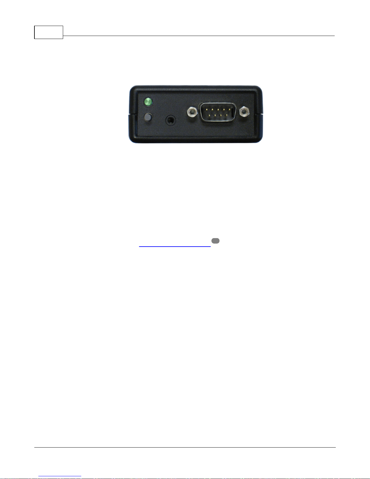
2.2 Front Panel
LED &
Read
Switch
Read
Switch
Port
DB9 Input Port
WedgeLink AT Front Panel
The WedgeLink AT front panel contains the following elements.
WedgeLink AT Keyboard Wedge6 Using WedgeLink AT
§ Red/Green bi-color LED
§ Built-in read switch
§ Connector for external read switch. This read switch connector requires a 2.5 mm sub-
miniature phone plug. Foot and hand switches are available from MicroRidge. If you
31
build your own, all that is required is a switch to provide a contact closure.
Copyright © 2015-2017 MicroRidge Systems, Inc.
Page 13
WedgeLink AT Keyboard Wedge
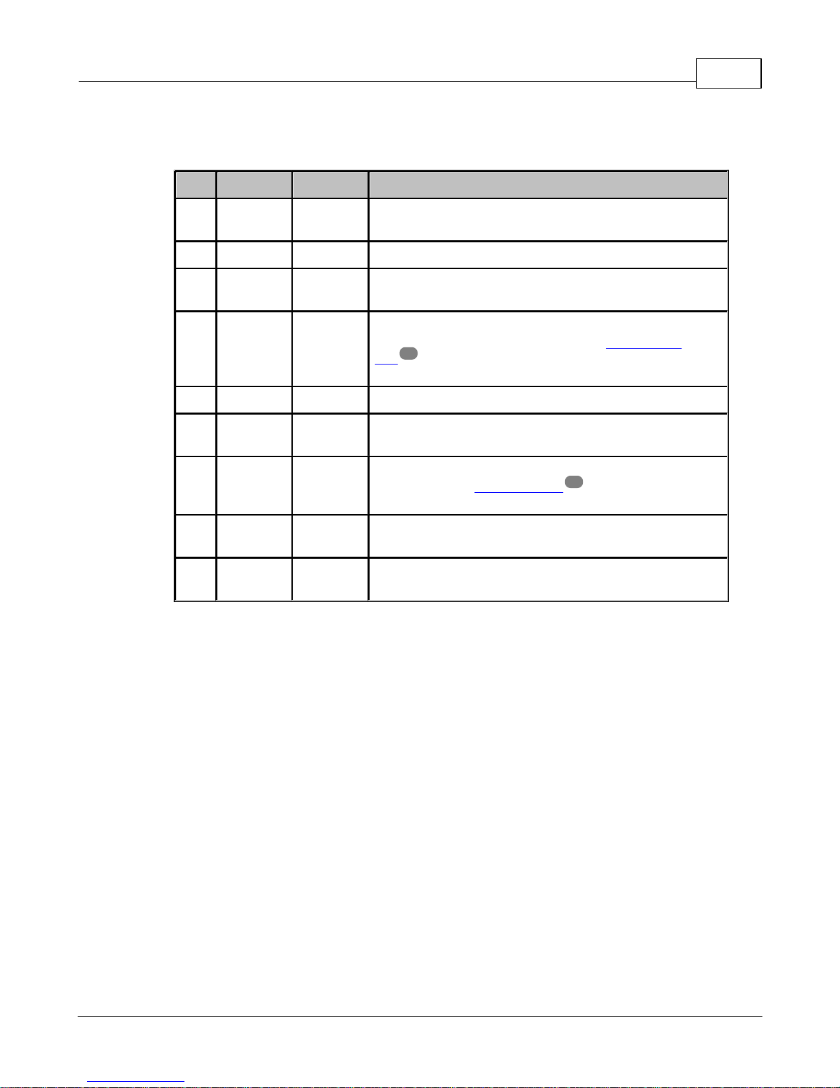
Pin
Function
Direction
Comments
1
DCD
--
This pin is used for modem signals and is not connected
on WedgeLink AT.
2
RxD
Input
Receive data. This line must be connected.
3
TxD
Output
Transmit data. This line must be connected if you are
sending commands to your serial device.
4
DTR
Output
Output handshake line. This line is normally high. If you
select "DTR low for 150 msec" on the Read Switch
Tab , this line will toggle low to high when the read
switch is pressed.
5
Ground
--
Signal ground. This line must be connected.
6
DSR
Input
Input handshake line. This line is not monitored by
WedgeLink AT.
7
RTS
Output
Output handshake line. The high/low state of this line is
controlled by an internal jumper on the WedgeLink AT
circuit board.
8
CTS
Input
Input handshake line. This line is not monitored by
WedgeLink AT.
9RI--
This pin is used for modem signals and is not connected
on WedgeLink AT.
§ DB9 male connector. This connector is similar to a standard PC serial port connector. The
function of each of the pins is described in the following table.
Using WedgeLink AT 7
19
9
Copyright © 2015-2017 MicroRidge Systems, Inc.
Page 14

2.3 Back Panel
RS-232 &
Prog Port
Reset
Button
Wedge
Port
WedgeLink AT Back Panel
The WedgeLink AT back panel contains the following elements.
WedgeLink AT Keyboard Wedge8 Using WedgeLink AT
§ USB connector for RS-232 and Programming. In order to use this port, you must install the
FTDI USB drivers from the WedgeLink AT CD.
5
§ Reset button. Pressing this button will restart the WedgeLink AT. Pressing this button will
not change any of the setup information in WedgeLink AT.
§ USB connector for keyboard wedge mode. Driver installation is not required for using this
port.
Power Supply & Data Transfer Port
The WedgeLink AT is powered through one of the USB ports accessible on the back panel.
WedgeLink AT will detect which port ("RS-232 & Prog" or "Wedge") is connected to your PC and
send the appropriate data to that port. If you connect both USB ports to your PC, WedgeLink AT
will send the data to the "RS-232 & Prog" port. There is no reason or advantage to connect both
of the WedgeLink AT USB ports to your PC.
Wedge Port
To use WedgeLink AT in the wedge mode, connect this port to a USB port on your PC. No
driver installation on your PC is required to use this port. This port will appear as an HID device
(Human Interface Device) to your PC. Both your keyboard and mouse are HID devices.
RS-232 & Prog Port
When using the Setup Program, or when you want to send your parsed data to a serial port on
your PC, connect this port to a USB port on your PC. In order to use this port you may need to
install the FTDI USB drivers from the WedgeLink AT CD.
Copyright © 2015-2017 MicroRidge Systems, Inc.
5
Page 15

WedgeLink AT Keyboard Wedge
2.4 Internal Jumper
Using WedgeLink AT 9
WedgeLink AT Internal RTS Handshake Jumper
The output on the RTS handshake line (pin 7 of the DB9 connector ) is controlled by an
internal jumper. To set the line to the high state, put the jumper in the V+ position. To set the
line to the low state, put the jumper in the V- position. The factory default for this jumper is the
V+ position.
2.5 Auto Baud Rate Detection
In order to communicate with an RS-232 connection, the serial parameters for WedgeLink AT
must match the serial parameters of the connected serial device. It is not uncommon for the user
to be unaware of the current serial parameters for their serial device. When you restart
WedgeLink AT, it can enter a mode that can determine the serial parameters of the connected
serial device. The serial parameters supported by WedgeLink At are as follows.
Baud Rates Supported
§ 600
§ 1200
§ 2400
§ 4800
§ 9600
6
§ 14.4K
§ 19.2K
§ 38.4K
§ 57.6K
Copyright © 2015-2017 MicroRidge Systems, Inc.
Page 16

WedgeLink AT Keyboard Wedge10 Using WedgeLink AT
Communication Parameters (Parity - Data bits - Stop bits) Supported
§ N-8-1
§ N-8-2
§ E-8-1
§ E-8-2
§ O-8-1
§ O-8-2
§ N-7-1
§ N-7-2
§ E-7-1
§ E-7-2
§ O-7-1
§ O-7-2
Enabling Auto Baud Rate Detection
By default the Auto baud rate detection feature is enabled on WedgeLink AT. Enabling and
disabling this feature is accessed from the Home Tab in the Setup Program.
15
Auto Baud Rate Detection
In order for WedgeLink AT to detect the serial parameters of the connected serial device, your
serial device must have a Send or Print button. If you must send a command to your serial
device to get a measurement, you will not be able to use the Auto Baud Rate Detection feature.
To automatically detect the serial parameters follow the steps below.
§ Connect one end of the USB cable to the WedgeLink AT "Wedge" or "RS-232 & Prog" port.
§ Connect the other end of the USB cable to a USB port on your computer and wait for the
front panel LED to turn off.
§ Connect your serial device to the DB9 male serial port on the WedgeLink AT.
§ Press and release the Reset button on the back of the WedgeLink AT.
§ The LED will briefly display red and then display green for 5 seconds.
§ When the LED displays green, the WedgeLink AT is in the Auto Baud Rate Detection mode.
§ Press the Print or Send button on your serial device while the green LED is on.
Copyright © 2015-2017 MicroRidge Systems, Inc.
Page 17

WedgeLink AT Keyboard Wedge
§ The results of the Auto Baud Rate Detection will be indicated by the red and green LEDs.
Green LED turns off without blinking No test data was received from a connected
Green LED blinks 5 times The serial parameters were determined from the
Red LED blinks 5 times The serial parameters for the data received
If WedgeLink AT is unable to determine the serial parameters, it may be due to one of the
following reasons:
§ The baud rate of your serial device does not match one of the supported baud rates.
Using WedgeLink AT 11
serial device. No changes were made to the
current WedgeLink AT serial parameters.
received data. If these serial parameters are
different than those currently stored in
WedgeLink AT, the new parameters will be
stored in WedgeLink AT.
could not be determined. No changes were
made to the current WedgeLink AT serial
parameters.
§ The communication parameters of your serial device does not match one of the supported
sets of communication parameters.
§ Not enough data characters were received from your serial device. Depending on the
characters being sent, WedgeLink AT can determine the serial parameters with as few as 3
characters or may require as many as 8 characters.
Copyright © 2015-2017 MicroRidge Systems, Inc.
Page 18

Page 19

WedgeLink AT Keyboard Wedge
3 Setup Program
The WedgeLink AT Setup Program is used to configure the parsing options and transfer these
options to and from the WedgeLink AT. Each tab in the Setup Program will be individually
discussed in the following sections. The setup tabs are as follows:
Home Tab This tab is used to locate the WedgeLink AT connected to your computer
Read Sw Tab The Read Switch tab is used to define the operation of the built-in and
Remove Tab Any characters to be removed from the input data packet are defined on
Replace Tab This tab allows you to replace specific characters with other characters.
Parse Tabs The 3 Parse tabs allow you to configure up to 3 parsing routines for the
15
and to transfer the setup information to and from the WedgeLink AT.
Additionally, the baud rate of your serial device and the end-of-packet
identification methods are set on this tab.
19
external read switches.
20
this tab.
21
22
input data packets.
Setup Program 13
Menu & Toolbar
The menu and toolbar provide access to the File New, Open and Save functions,
Communications Test Program ( ), Send Setup to WedgeLink ( ), and the Help items. The
File New, Open and Save functions are only enabled when a WedgeLink AT is detected by the
Setup Program.
The Communications Test Program (ComTestSerial) is a serial communications test program
that is useful in determining what information is actually being sent from your serial device.
Refer to the ComTestSerial section for more detail.
29
Parameters Update Notice
If you make changes to any of the configuration parameters, you must transfer the updated
parameters to the connected WedgeLink AT. The transfer is accomplished by clicking the "Send
Setup to WedgeLink" button on the Home Tab or the toolbar button. To make it apparent
15
that the WedgeLink AT contains the parameters specified in the Setup Program or that the
parameters need to be updated, a message in red text or green text is displayed on each of
the tabs.
Copyright © 2015-2017 MicroRidge Systems, Inc.
Page 20

WedgeLink AT Keyboard Wedge14 Setup Program
Home Tab
The update message on the Home tab is displayed below the "Send Setup to WedgeLink"
button.
WedgeLink parameters are current: Parameters displayed are the same as
stored in WedgeLink.
WedgeLink parameters need to be updated: Parameters have changed. You need to
send the values to WedgeLink.
Other Tabs
The update message on the other tabs is displayed at the bottom of the program window.
WedgeLink parameters are current: The parameters displayed are the same as
stored in WedgeLink.
WedgeLink parameters need to be updated: The WedgeLink parameters have been
modified. You need to send the modified
values to WedgeLink.
3.1 Entering Special Characters
Several of the tabs allow you to enter special characters such as carriage returns, tabs, function
keys, etc. These special characters are entered by including the character code within brackets.
For example, to enter a carriage return or enter key you can enter any of the following strings:
{\x0d}, {\x0D}, {cr} or {CR}. The {\x0d} and {\x0D} represent the hex code for a carriage return. If
you enter one of these hex codes or {cr}, the entered string will be changed to {CR} when you
leave the input field. These same rules apply to other special characters such as Tab and Esc.
To enter the function keys, put the name of the function keys within brackets. You can enter
function keys {F1} to {F12}. Function key combinations that are proceeded with a Shift, Ctrl or
Alt are not currently supported. Function keys can only be entered in the prefix and suffix field
on the Parsing Tabs .
Remember that WedgeLink AT in the wedge mode will only send normal keyboard characters to
your PC. If you enter characters such as {LF}, {\x0a}, {\xa2}, etc., WedgeLink AT will not send
these characters to the wedge port. If you are sending the data out the RS-232 port, WedgeLink
will send these special characters.
Following is a list of the more common special characters that you may need to use:
Carriage return {CR}
Tab {Tab}
Esc {Esc}
22
F1 {F1}
F2 {F2}
F11 {F11}
Copyright © 2015-2017 MicroRidge Systems, Inc.
Page 21

WedgeLink AT Keyboard Wedge
3.2 Program Tabs
The WedgeLink AT Setup Program consists of a series of tabs for the various configuration
functions. The functions on each tab can be enabled or disabled from the Home Tab or from
each individual tab. An easy way to test your parsing setup is to run ComTestSerial ( ) from
the toolbar and then send data from your serial device.
Remember, in order to use the Setup Program, you must connect WedgeLink AT to your PC via
the "RS-232 & Prog" port.
3.2.1 Home Tab
Setup Program 15
The Home Tab is initially displayed when you run the Setup Program. If you are not using
read switches or not doing parsing, this is the only tab you will need to access. To use
the Setup Program, connect WedgeLink AT to your computer using the "RS-232 & Prog" port
and then press the "Find the WedgeLink" button. When the Setup Program finds the WedgeLink
AT, the Setup Program will appear similar to the screen shown above.
The Setup Program examples shown in this User's Guide illustrate a user defined setup. The
WedgeLink AT default parameters will be different than those shown in the examples.
Copyright © 2015-2017 MicroRidge Systems, Inc.
Page 22

WedgeLink AT Keyboard Wedge16 Setup Program
Connection status
This group of controls allows you to send and receive setup data to and from WedgeLink AT. To
view information about WedgeLink AT (serial number, version, etc.) press the "WedgeLink
Information" button. If you have made changes to the setup, a message below the "Send Setup
to WedgeLink" button will be displayed in red to indicate that you need to send the new setup
information to WedgeLink AT.
Pressing the toolbar button, is equivalent to pressing the "Send Setup to WedgeLink" button.
The advantage of the toolbar button is that this button is accessible from all of the tabs.
After a WedgeLink AT is found, the group title will be updated to indicate the serial port that the
WedgeLink AT is connected to. The baud rate and communication parameters for the "RS-232
& Prog" port is fixed at 9600-N-8-1.
Connected serial device communications
The first item in this group displays the baud rate and communication parameters for the input
DB9 serial port. This is the port that you will connect your serial device to. This port is
configured similar to a standard PC serial port. The baud rate and communication parameters
setting for this port must match the setting in your serial device. For a description of the function
of each pin on the DB9 connecter refer to the Front Panel section .
6
You can manually set the baud rate and communication parameters for the connected serial
device or have WedgeLink AT automatically determine the serial port settings. Refer to the Auto
Baud Rate Detection section for more details. To enable auto baud rate detection or
manually set the serial communication parameters, press the "Set Parameters " button. The
9
18
default setting is to automatically detect the baud rate and communication parameters.
Input end-of-packet
Normally, WedgeLink AT processes packets when an end-of-packet identifier is received. If you
select "Send immediately", all parsing is disabled and WedgeLink AT will send the data to your
PC as soon as it is received. What gets sent to your PC depends on what port on the
WedgeLink AT is connected to your PC.
Wedge Port Only standard keyboard characters will be sent to the HID connection
on your PC. Standard keyboard characters consist of BkSp (\x08), Tab
(\x09), CR (\x0d), Esc (\x1b) and ASCII 32 (\x20) to 126 (\x7e). Any
other characters will not be sent to your PC
RS-232 & Prog Port All received characters will be sent to a virtual serial port on your PC.
Most serial devices send data packets terminated with a carriage return (CR) or a carriage return
and a line feed (CR/LF). If this is the case for your serial device, simply select the "Character"
for the end-of-packet type and select the "CR, CR/LF or LF/CR" radio button. If your serial
device sends a different character such as a Tab, select the appropriate character in the "Other"
list box.
Copyright © 2015-2017 MicroRidge Systems, Inc.
Page 23

WedgeLink AT Keyboard Wedge
If your serial device does not send a specific character, select the "Gap time" for the end-ofpacket type and enter the gap time in milliseconds (msec). You may have to try various gap
times if you use this feature.
Minimum packet size
You can specify a minimum packet that must be received in order for the packet to be processed.
For example, your serial device sends a series of carriage returns (CR) between the real data
packets. If WedgeLink AT is looking for a {CR} as the end-of-packet character, simply require
the minimum packet size to be 2. WedgeLink AT will disregard those single character {CR}
packets.
Enable functions
The check boxes in the "Enable functions" group allow you to enable and disable specific
parsing features. These features can also be enabled and disabled by a check box on the
individual tabs.
Setup Program 17
File Save & Read
You can save WedgeLink AT setups and reload them from a file. In order to use the file read
and write functions, the Setup Program must have found a WedgeLink AT. The file read and
write functions will be disabled when no WedgeLink AT is connected to the Setup Program. This
feature is useful if you have multiple WedgeLink ATs to program with the same parameters or if
you want to have a backup copy of the configuration parameters in a WedgeLink AT.
Copyright © 2015-2017 MicroRidge Systems, Inc.
Page 24

3.2.1.1 Input Serial Port Parameters
WedgeLink AT Keyboard Wedge18 Setup Program
This dialog is displayed when you press the "Set Parameters" button on the Home Tab, and
allows you to enable and disable the Automatic Baud Rate Detection . All combinations of the
9
baud rates and communication parameters shown in the dialog are supported by WedgeLink AT.
Copyright © 2015-2017 MicroRidge Systems, Inc.
Page 25

WedgeLink AT Keyboard Wedge
3.2.2 Read Switch Tab
Setup Program 19
There are 2 read switch options available on WedgeLink AT. The built-in read switch is located
in the lower left corner of the front panel. An external read switch can also be plugged into the
front panel. Both of the read switches operate in the same manner and each read switch can be
individually configured. The options available for each read switch depend on the state of the
"Serial device send continuously, use read switches" check box.
Some serial devices require that a handshake line be briefly pulled low and then high before the
serial device will send any data. If the "Serial device send continuously, use read switches"
check box is not checked, you can select "DTR low for 150 msec" from the drop down list. DTR
is pin 4 on the DB9 connector. Refer to the Front Panel section for a description of the DB9
pins.
6
Copyright © 2015-2017 MicroRidge Systems, Inc.
Page 26

3.2.3 Character Removal Tab
WedgeLink AT Keyboard Wedge20 Setup Program
This tab allows you to specify individual and groups of characters to be removed from the data
received from your serial device. If items on this tab are enabled, each character that is received
is checked to see if it is to be removed. If a match is found, the character is immediately
discarded and never saved.
Copyright © 2015-2017 MicroRidge Systems, Inc.
Page 27

WedgeLink AT Keyboard Wedge
3.2.4 Character Replacement Tab
Setup Program 21
This tab allows you to change a specific character to another character. If items on this tab are
enabled, each character that is received is checked to see if it is to be replaced with another
character. If a match is found, the character is immediately replaced.
A very common use of the replace feature is to replace commas with tabs or carriage returns. If
you are sending to a program such as Excel, replacing the commas with tabs or carriage returns
can allow you to place each number from the input packet into a different cell. For example, let's
assume your input packet is:
2.456, 7.932, 12.343{CR}
After removing the spaces (Character Removal Tab ), and replacing commas with tabs, you
end up with the following:
2.456{Tab}7.932{Tab}12.343{CR}
Excel will now place each of the 3 numbers in a different cell.
20
Copyright © 2015-2017 MicroRidge Systems, Inc.
Page 28

3.2.5 Parsing Tabs
WedgeLink AT Keyboard Wedge22 Setup Program
The 3 parsing tabs allow you to do the following parsing on the input data packet:
§ Parse the packet with the setup on the tab if the data contains a specific string.
§ Disregard the packet if the data does not contain a specific string.
§ Use a specific range of character positions in the packet.
§ Find the first numeric field in the specified range of character positions.
§ Add a prefix to the output data packet.
§ Add a suffix to the output data packet.
§ Add an end-of-packet character to the output data packet.
Copyright © 2015-2017 MicroRidge Systems, Inc.
Page 29

WedgeLink AT Keyboard Wedge
Match String
The "Use Match String" feature allows you to control if the packet is parsed with the setup
specified on the tab. If the "Parsing Group" is enabled and the "Use Match String" is not
enabled, the input data packet will always be parsed based on the features selected on the tab.
The match string is a case sensitive string and the steps to take depend on whether a match is
found or not found. The maximum length of a match string is 20 characters. Special characters
such as {Tab} count as 1 character, not 5 characters.
Match Found
If the match string is found, the following actions can be taken:
Delete Packet Delete the packet. Nothing will be sent to your PC.
Parse packet & stop Parse the packet based on the features you have selected on
Parse & go to next parse Parse the packet based on the features you have selected on
Setup Program 23
the parsing tab. The parsed packet will be sent to your PC. The
parsing processing will stop at this point.
the parsing tab. The parsed packet will be sent to your PC. Go
to the next enabled parsing tab and follow the procedures on this
next tab. This option is not displayed for the Parsing #3 Tab.
Go to next parse Do not parse the data packet with the features specified on the
tab. Go to the next enabled parsing tab and follow the
procedures on this next tab. This option is not displayed for the
Parsing #3 Tab.
Match Not Found
If the match string is not found, the following actions can be taken. These actions are identical
to the actions available when a match is found.
Delete Packet Delete the packet. Nothing will be sent to your PC.
Parse packet & stop Parse the packet based on the features you have selected on
the parsing tab. The parsed packet will be sent to yout PC. The
parsing processing will stop at this point.
Parse & go to next parse Parse the packet based on the features you have selected on
the parsing tab. The parsed packet will be sent to your PC. Go
to the next enabled parsing tab and follow the procedures on this
next tab. This option is not displayed for the Parsing #3 Tab.
Go to next parse Do not parse the data packet with the features specified on the
tab. Go to the next enabled parsing tab and follow the
procedures on this next tab. This option is not displayed for the
Parsing #3 Tab.
Copyright © 2015-2017 MicroRidge Systems, Inc.
Page 30

WedgeLink AT Keyboard Wedge24 Setup Program
Using the match string feature can be very useful when you have multiple data fields contained
within an input data packet. For example, let's assume you are receiving a data packet that
contains X, Y and Z coordinate values. An example of what the input data packet might look like
is shown below. In this example, it is assumed that the measurements are always right justified
in an 8 character field. The first 2 rows show the character positions and the 3rd row is the
actual data received from your serial device.
1 2 3 4 5 6
1234567890123456789012345678901234567890123456789012345678901
Coordinate measurements = X: 12.435, Y: -3.451, Z: 2.498{CR}
What you want is to extract the 3 measurements and output a {Tab} after the X and Y
measurements, and output a {CR} after the Z measurement. The final output string would
appear as follows.
12.435{Tab}-3.451{Tab}2.498{CR}
An overview of the setup required to parse this data is as follows:
Parse #1 Tab
Match string = X:
Match found = Parse & go to next parse
Match not found = Delete packet
Find first numeric field = Checked
Add end-of-packet character = Tab
Parse #2 Tab
Match string = Y:
Match found = Parse & go to next parse
Match not found = Delete packet
Use character positions = 39 to 49 (you could also use 41 to 48)
Find first numeric field = Checked
Add end-of-packet character = Tab
Parse #3 Tab
Match string = Z:
Match found = Parse packet & stop
Match not found = Delete packet
Use character positions = 51 to 61 (you could also use 53 to 60)
Find first numeric field = Checked
Add end-of-packet character = CR
Copyright © 2015-2017 MicroRidge Systems, Inc.
Page 31

WedgeLink AT Keyboard Wedge
Use Character Positions
This feature allows you to specify the character positions in the input data packet that will be
used by the parsing on the current tab. It you enter a starting character position larger than the
ending position, the numbers will be reversed when you leave the tab.
Find First Numeric Field
A numeric field consists of at least 3 characters. The first character can be a space, + (plus), (minus), . (decimal point) or 0 to 9. The second and following characters must be a decimal point
or 0 to 9. Only a single decimal point is allowed in the selected field. If you do not check
"Decimal point required", it will not matter if a decimal is present in the numeric field.
If you use the "Find first numeric field" feature, the data that is sent to the output packet is only
the number that has been found. You will typically need to add an end-of-packet character to
the output string.
Prefix & Suffix
Setup Program 25
You can add a prefix or suffix string to be included with the output data packet. The maximum
length of a prefix or suffix string is 25 characters. Special characters such as {Tab} count as 1
character, not 5 characters. You can also add function key F1 to F12 to a prefix and suffix. For
F1 enter {F1}, for F2 enter {F2}, etc.
Add End-of-Packet Character
This feature allows you to add a specific end-of-packet character to the output data packet. You
can add this character here or you could include the character as part of a suffix string. If you
use the "Find first numeric field" feature, you will typically need to add an end-of-packet
character.
Copyright © 2015-2017 MicroRidge Systems, Inc.
Page 32

Page 33

WedgeLink AT Keyboard Wedge
4 Keyboards
The WedgeLink AT factory default configuration emulates the United States keyboard. A total of
4 keyboards are currently emulated by WedgeLink AT. The emulated keyboards are as follows:
§ English (United States, QWERTY). Supports all of the keyboard characters that generate
an ASCII character code.
§ French (Belgium, AZERTY). No support for characters that require multiple key presses to
produce a single character.
§ French (France, AZERTY). No support for characters that require multiple key presses to
produce a single character.
§ German (Germany, QWERTZ). No support for characters that require multiple key presses
to produce a single character.
Since keys such as F1, F2, etc. are not represented by an ASCII character code, these keys are
not supported. In order for your PC to properly receive characters from a WedgeLink AT, the
keyboard selected via your PC Control Panel must match the keyboard selected in the
WedgeLink AT.
Keyboards 27
Selecting a WedgeLink AT Keyboard Type
The keyboard type can be changed by sending one of the following commands from
ComTestSerial to WedgeLink AT. Each command is 5 characters long (<$:KU, etc.). All
29
characters in the command should be upper case. A carriage return (Enter key) is not required
at the end of the command. In order to use the following commands, the WedgeLink AT must be
connected to a PC USB port via the RS-232 & Prog port on the WedgeLink AT.
<$:KU English (United States, QWERTY)
<$:KB French (Belgium, AZERTY)
<$:KF French (France, AZERTY)
<$:KG German (Germany, QWERTZ)
When one of the keyboard type commands is sent to a WedgeLink AT, a response from the
WedgeLink AT shows what the previous keyboard type was and what the new keyboard type is.
An example of entering the <$:KF command to switch to the France keyboard is shown below.
<$:KF
Previous keyboard type = English (United States, QWERTY)
New keyboard type = French (France, AZERTY)
WedgeLink AT Help Text
When WedgeLink AT is connected to ComTestSerial via the RS-232 & Prog port, you can send
the command <CF from ComTestSerial to get a summary of the keyboard change commands.
Copyright © 2015-2017 MicroRidge Systems, Inc.
Page 34

Page 35

WedgeLink AT Keyboard Wedge
5 ComTestSerial
ComTestSerial 29
ComTestSerial is a Serial Communications Test Program and is included on the WedgeLink AT
CD. A copy of ComTestSerial is also installed on your PC when you install the WedgeLink AT
Setup Program. ComTestSerial is included so that you can test and verify the output coming
from your serial device. If you access ComTestSerial from the Setup Program after you have
found a WedgeLink AT, ComTestSerial will use the serial port that the WedgeLink AT is
connected to.
When ComTestSerial is loaded from the WedgeLink AT Setup Program, there are several
buttons that are predefined with commands for WedgeLink AT. The predefined buttons are
shown below. The command for each of the buttons is shown in the parenthesis after the
command button label.
Copyright (<*) Get copyright and some setup information from WedgeLink AT.
Version Number (<V) Get the WedgeLink AT firmware version number.
Blink LEDs (<L) Blink the LEDs on the WedgeLink AT.
Warm Start (<W) Make the WedgeLink AT do a warm start. This is the same as
pressing the reset button on the back of the WedgeLink AT.
Copyright © 2015-2017 MicroRidge Systems, Inc.
Page 36

WedgeLink AT Keyboard Wedge30 ComTestSerial
Data in RxD Buffer (<D) If you send data to the WedgeLink AT DB9 port from your serial
device and the red LED stays on, this indicates WedgeLink AT has
not received an end-of-packet character. If you press this button,
the number of bytes and the actual data in the WedgeLink AT input
buffer will be displayed.
Additional copies of ComTestSerial can also be downloaded from the ComTestSerial page on
the MicroRidge web.
Copyright © 2015-2017 MicroRidge Systems, Inc.
Page 37

WedgeLink AT Keyboard Wedge
Hand Switch
P/N: HNDSW-MPLG
The hand switch connectes to the read switch port
on the front of the WedgeLink AT.
The cable length on the hand switch is 6'
Foot Switch
P/N: FTSW-MPLG
The foot switch is used for the same functions as the
hand switch.
The cable length on the foot switch is 6'
6 Accessories
Several accessories are available for use with WedgeLink AT. These items are available for
purchase directly from the MicroRidge web site at the following store:
WedgeLink Store: www.microridge.com/store_wedgelink.htm
Accessories 31
Copyright © 2015-2017 MicroRidge Systems, Inc.
Page 38

Page 39

WedgeLink AT Keyboard Wedge
Hardware keyboard wedge for direct RS-232 input.
This hardware wedge contains extensive parsing
capabilities that can be configured by a Windows
Setup Program. Baud rates from 600 to 57.6K are
supported. Includes 6' USB cable for connecting
the WedgeLink AT to your PC.
Hardware keyboard wedge for direct RS-232 input.
The baud rate and communication parameters are
permanently set and cannot be changed by the
user. No parsing is available with this wedge.
Available preset baud rates range from 4800 to
19.2K.
Software keyboard wedge for users that do not
need to perform any data parsing on the input
packets. WedgeLink Lite does allow you to add a
date/time stamp as a data prefix.
Keyboard Wedges from MicroRidge 33
7 Keyboard Wedges from MicroRidge
WedgeLink AT is a member of the WedgeLink keyboard wedge family manufactured by
MicroRidge. Within the keyboard wedge family there are both software and hardware wedges
for capturing RS-232 serial data and sending this data to a PC via simulated keyboard entry.
The members of the RS-232 WedgeLink family are briefly described below. For more
information about the WedgeLink family go the the WedgeLink page on the MicroRidge web.
WedgeLink AT
WedgeLink SP
WedgeLink LE
Copyright © 2015-2017 MicroRidge Systems, Inc.
Page 40

WedgeLink SE
Software keyboard wedge for users that need full
data parsing capabilities.
WedgeLink AT Keyboard Wedge34 Keyboard Wedges from MicroRidge
Copyright © 2015-2017 MicroRidge Systems, Inc.
Page 41

WedgeLink AT Keyboard Wedge
8 Warranty Information
The standard MicroRidge warranty for products it manufactures and resells is described below:
§ MicroRidge warrants that equipment manufactured by MicroRidge to be free from defects
in material and workmanship, when properly maintained under normal use, for a period of
twelve (12) months from date of purchase of the product (the “warranty period”). Some
products sold and distributed by MicroRidge are warranted by the manufacturer of the
products.
§ Warranty for gage and RS-232 interface cables is 30 days from date of shipment.
§ Products which do not conform to their description or which are defective in material or
workmanship will, by MicroRidge decision, be replaced or repaired, or, at MicroRidge’s
option, credit for the original purchase price may be allowed provided that customer notifies
MicroRidge in writing of such defect within thirty (30) days of discovery and returns such
products in accordance with the MicroRidge instructions. No products may be returned
without MicroRidge prior written authorization.
§ This warranty does not apply to any product which has been subjected to misuse, abuse,
negligence or accident by the customer.
Warranty Information 35
§ MicroRidge makes no other warranty or representation of any kind with respect to the
products, either express or implied, including without limitation, that of merchantability or
fitness for a particular use. Failure to make any claim in writing, or within the thirty (30) day
period set forth above, shall constitute an irrevocable acceptance of the products and an
admission by the customer that the products fully comply with all terms, conditions and
specifications of customer’s purchase order. MicroRidge shall not be liable for direct,
indirect, incidental, special or consequential damages, under any circumstances, including,
but not limited to, damage or loss resulting from inability to use the products, increased
operating costs or loss of sales, or any other damages. To make a claim under this
warranty, customer must notify MicroRidge in writing within the warranty period.
§ Customer will pay all shipping charges (and duty and taxes) for equipment returned to
MicroRidge for warranty service. MicroRidge will pay shipping charges for equipment
returned to customer in North America. Customers outside the USA are responsible for
duty and taxes on equipment returned to them.
§ Software developed by MicroRidge is warranted to operate in accordance with the
software documentation on the hardware specified in such documentation, for a period of
six (6) months from date of shipment. During the warranty period, MicroRidge will at no
charge correct any programming error in the software that interferes with normal operation
of the software provided that MicroRidge is able to reproduce such error on MicroRidge
computer.
Copyright © 2015-2017 MicroRidge Systems, Inc.
Page 42

Page 43

WedgeLink AT Keyboard Wedge
9 Contact MicroRidge
Email:
Support: support@microridge.com
Sales: sales@microridge.com
Information: info@microridge.com
Phone:
Support: 541.593.1656
Sales: 541.593.3500
Main office: 541.593.1656
Fax: 541.593.5652
Contact MicroRidge 37
Mailing Address:
MicroRidge Systems, Inc.
PO Box 3249
Sunriver, OR 97707-0249
Shipping Address:
MicroRidge Systems, Inc.
56888 Enterprise Drive
Sunriver, OR 97707
Note: There is no mail delivery to this address. This address should only be used for
package delivery services such as UPS, FedEx, etc.
Web: www.microridge.com
Copyright © 2015-2017 MicroRidge Systems, Inc.
 Loading...