

Page 1

NHT-310
User Manual
Page 2

II
Release 2.5 June 2017
Design development and manufacturing
MICRORAD
P.zza delle Azalee 13/14
05019 Orvieto (TR) – ITALIA
Tel +39 0763393291
Fax +39 0763394423
email info@microrad.it
web www.microrad.it
Page 3

III
INDEX
1 GENERAL INFORMATION .............................................................................................. 1
1.1 Application .................................................................................................................... 1
1.2 About the instrument ..................................................................................................... 1
1.3 Operating modes ........................................................................................................... 1
1.3.1 Single EMF measurement .................................................................................... 1
1.3.2 Long-term Monitoring ........................................................................................... 2
1.3.3 NHT310 remote control through MicroLink software ............................................ 2
1.3.4 Downloading data to PC ....................................................................................... 2
1.4 Measurement probes .................................................................................................... 3
1.5 GPS module and temperature sensor ........................................................................... 3
1.6 Equipment configuration ................................................................................................ 4
1.7 NHT310 technical specifications .................................................................................... 5
1.7.1 NHT310 base unit ................................................................................................. 5
1.7.2 Measurement probes ............................................................................................ 6
1.8 Standard compliance ..................................................................................................... 7
2 SAFETY INSTRUCTIONS ............................................................................................... 8
2.1 Foreword ....................................................................................................................... 8
2.2 Correct use ................................................................................................................... 8
3 CERTIFICATION AND WARRANTY ................................................................................ 9
3.1 Certification ................................................................................................................... 9
3.2 Warranty ....................................................................................................................... 9
3.3 Limitation of warranty .................................................................................................... 9
4 UNIT DESCRIPTION ..................................................................................................... 10
4.1 Front panel legend ...................................................................................................... 10
4.2 Connectors and interfaces legend ............................................................................... 13
5 PREPARATION FOR USE ............................................................................................. 15
5.1 Unpacking ................................................................................................................... 15
5.2 Storage ....................................................................................................................... 15
5.3 Connecting the probes ................................................................................................ 15
5.4 Power supply ............................................................................................................... 16
5.4.1 Battery autonomy ............................................................................................... 17
5.4.2 Battery replacement ........................................................................................... 17
6 OPERATION .................................................................................................................. 18
6.1 Base unit switching on ................................................................................................. 18
6.2 Main measuring display screen ................................................................................... 20
6.3 Recording measured value .......................................................................................... 23
6.3.1 Single storing ...................................................................................................... 23
6.3.2 Monitoring........................................................................................................... 24
6.4 Measurement download and display ........................................................................... 25
6.5 Spatial Average Mode ................................................................................................. 25
6.6 Alert levels .................................................................................................................. 26
6.7 Factory reset ............................................................................................................... 27
Page 4

IV
7 MICROLINK SOFTWARE .............................................................................................. 28
7.1 Description .................................................................................................................. 28
7.2 Software installation .................................................................................................... 28
7.3 Software main screen .................................................................................................. 28
7.4 Functions .................................................................................................................... 29
7.5 NHT310 parameters setting (Settings) ........................................................................ 30
7.6 Download data from NHT310 (Download) ................................................................... 32
7.6.1 SnapShots panel ................................................................................................ 33
7.6.2 Monitoring panel ................................................................................................. 34
7.6.3 Monitoring data graphic format ........................................................................... 36
7.7 Microsoft Excel™ data export ...................................................................................... 38
7.8 NHT310 remote control ............................................................................................... 39
7.9 GPS and Google Maps ............................................................................................... 39
7.10 NHT310 firmware update ......................................................................................... 41
APPENDIX A COMMUNICATION PROTOCOL ................................................................ 42
Page 5

1 GENERAL INFORMATION
1.1 Application
Human exposure to electromagnetic fields (not ionizing radiation) is nowadays
a very critical subject with which almost all countries must deal. Technical and
normative bodies work alongside government institutions to enact new
guidelines and decrees regarding maximum permitted exposure levels for
populations and workers.
The measurement equipment for this type of analysis must suit the technical
requirements from the guidelines and must provide the user with qualified
physical parameters for compliance with legally required thresholds.
1.2 About the instrument
NHT310 is the new Microrad solution for the measurement of electromagnetic
fields. Besides being handy and compact, the instrument operates in the
widest frequency band possible for a handheld instrument.
It is user-friendly and provides extremely reliable measurements; it also
provides the operator with local temperature and GPS coordinates of the site
being measured for inclusion in a final report.
1.3 Operating modes
1.3.1 Single EMF measurement
The main application of NHT310 is to perform wideband electromagnetic field
measurements allowing the user to make evaluations in relation to established
protective safeguards. The system uses a variety of probes to measure
specific physical parameters (magnetic induction, magnetic field and electric
field) according to the frequency band of interest.
On the instrument LCD display, are always displayed:
Instantaneous isotropic value ISO of measured field.
Time average isotropic value (AVG) of measured field.
Spatial average value SPT of measured field.
Maximum isotropic value MAX of measured field.
Alarm threshold ALM.
Geographic coordinates GPS.
Ambient temperature.
Date and time.
The instrument can be used in direct operating mode via the front keyboard
panel and the measurements can be viewed on the LCD display. The user can
store single measurement data by pressing the [STORE SINGLE] command.
Each measured value is stored in a specific memory portion for single
Page 6

NHT310 1. General information
2
measurements (for a total of 432 measurements) along with the information
regarding date and time, GPS coordinates, and ambient temperature.
1.3.2 Long-term Monitoring
NHT310 can perform up to 8 data acquisition sequences for long-term
monitoring of broadband electromagnetic fields. This mode is particularly
useful for low frequency magnetic induction measurements, since it is possible
to follow the possible fluctuation of field values depending on the daily
variation of the current flow in the electric lines or in the transformation cabins
(field source).
The user can initiate the acquisition sequence by simply pressing the [SHIFT]
key and then the [STORE MONIT] key.
Each monitoring can extend to full memory space (over 21’500 acquisitions) or
until the user wishes to interrupt the process by pressing any key on the
instrument.
1.3.3 NHT310 remote control through MicroLink software
This operation mode is recommended in order to avoid where possible the
influence of the user's presence on the environment being measured (mainly
for low and high frequency electric field analysis) or when there is a
requirement to install the measurement system in a screened and controlled
space (anechoic chamber for EMC testing). In such a situation it is strongly
recommended that a wooden tripod with variable height (optional) is used.
NHT310 can be remotely managed through a fiber optic connection to an
external PC. This operation is possible with the MicroLink software. MicroLink
allows the total remote control of the NHT310 unit by displaying on PC screen
the same keys of the instrument keyboard, making the system easy to use.
The software displays the measured data in real time and simultaneously
displays the amplitude / time graph of the field being analyzed.
In remote mode, it is possible to store single data or to start and stop
monitoring sequences.
1.3.4 Downloading data to PC
All measured values, recorded both as single acquisition or continuous
monitoring, can be downloaded to an external PC through the fiber optic cable
using MicroLink software.
Once the values have been transferred, they can be viewed and analyzed
within the MicroLink software and saved on a hard disk or other mass storage
units for later reference.
The software allows the numeric and tabular display of the field values as well
as the display of amplitude / time diagram with zoom function in the time
window of interest.
Page 7

NHT310 1. General information
3
Data export in tabular format (Excel compatible) and graphics, jpeg or bitmap
format, is also possible.
Using MicroLink software, the user can send configuration data to the device
in order to set the threshold for a high field acoustic alarm, set the sampling
interval between an acquisition and the next in long-term monitoring, set the
time interval to calculate the moving average with high frequency probes
(default value is 6 minutes as per international regulations), set the date and
time.
MicroLink is also able to calculate the 24-hour moving average on monitoring
sequences that exceed that duration.
1.4 Measurement probes
Various measurement probes are available for use in conjunction with NHT310
for both magnetic and electric field measurements, with frequency bands
ranging from dc up to 40 GHz.
The NHT310 automatically recognizes each probe when it is inserted.
A detailed list of available probes is given in section 1.7.2.
1.5 GPS module and temperature sensor
NHT310 integrates a GPS module to acquire geographic coordinates as
reference to the area in which the measurements were carried out.
In case of outdoor activities, it is always recommended to add the GPS data
related to the measurement site in order to mention them in the final report.
GPS associates not only geographic information but also the exact time (UTC
time).
No other external device is required to perform these operations as the
NHT310 performs the measurement and automatically provides field values
together with GPS coordinates of the site. The MicroLink software can directly
show them on Google Maps™.
In addition NHT310 integrates a temperature sensor acquiring the
temperature value during measurement activity.
Since the sensor is integrated into the front of the instrument, it is necessary to
consider that, as the meter shell is a good thermal conductor, the
measurement may be influenced by the operator's hand temperature. In order
to have exact temperature values, the instrument must be used with a tripod
support.
Page 8

NHT310 1. General information
4
1.6 Equipment configuration
The basic unit NHT310 is delivered in the standard configuration including:
NHT310 basic unit for measuring, storing and display field data
Fiber optic cable (10 meters length)
Fiber-USB adapter to link fiber optic to PC
USB A/B adapter cable
Battery charger
Rechargeable batteries
Sturdy carrying case with IP67 protection class
MicroLink software and user manual (available on www.microrad.it)
ISO 9001:2008 calibration certificates
In order to work correctly, the NHT310 meter must be connected to a
measurement probe from those available for this model.
Page 9
NHT310 1. General information
5
1.7 NHT310 technical specifications
1.7.1 NHT310 base unit
PROBE TYPE
Frequency range From DC to 18GHz using several B, E, H probes
DISPLAY
Type Transflective LCD monochrome COG (chip on glass)
Size 7 cm , 128x64 dots
Backlight Electroluminescent screen 10s/continuous selectable
MEASUREMENT FUNCTIONS
Measurement units mW/cm², W/m², V/m, A/m, Tesla
Display range
from 0.0001 to
999999 (
depending on
probe
and
measurement unit)
Result type (isotropic, RSS)
I
nstantaneous (ACT), Maximum
(MAX),
Average (AVG),
Median
Time average 6min std, from 4s to 30 min (step 2s ), software selectable
Moving average 24h calculated by MicroLink
STORAGE MEMORY
Samples 21.504 (8 monitoring sequences) / 432 (snapshot)
INTERFACES
Optical interfaces Serial, full duplex
Probe input Plug-and-play auto detection, connector LEMO™
GPS
Receiver
Sensitivity
-
163dBm, 48 channels, L1 C/A code, update
rate 4Hz
Time to first position (TTFF) typical < 60 seconds
GENERAL SPECIFICATIONS
Recommended calibration interval 24 months
Battery
Alkaline
or rechargeable
NiMH, 4 x AA size (Mignon), 2800
mAh
Battery operation time > 72 ore (backlight and GPS off)
Charging time 4 hours
Battery level indication 100%, 66%, 33%, < 10%
Operative Temperature range -10 °C to +50 °C
Storage Temperature range -20 °C to +70°C
Humidity 5 to 95%, non-condensing
Size (h x w x d) 160 x 98 x 30 mm (without probe)
Weight Approx 400 g (including batteries without probe)
Accessories (included)
Rechargeable batteries, AC charger, fiber optic cable
(10mt), USB-Optical Converter, User manual, MicroLink
software, probes calibration certificate
Note: technical specifications are subject to change without any prior notice.
Page 10

NHT310 1. General information
6
1.7.2 Measurement probes
Radio-frequency probes
P/N Probe 01E 02E 02H 03E 04E
Frequency range 100 kHz - 6.5 GHz 400 kHz - 30 MHz 300 kHz - 30MHz 100k Hz - 18GHz 3 MHz - 40GHz
Frequency Response Flat Flat Flat Flat Flat
Measurement range 0.2 - 350 V/m 2 - 800 V/m 0.016 - 16 A/m 0.8 - 340 V/m 0.5 - 350 V/m
Directivity Isotropic Isotropic Isotropic Isotropic Isotropic
Calibration interval 24 months 24 months 24 months 24 months 24 months
Operative temperature 0°C - 50°C 0°C - 50°C 0°C - 50°C 0°C - 50°C 0°C - 50°C
Low-frequency probes
P/N Probe 11E e 33E 10B 20B (100 cm2) 30B 33B (100cm2)
Frequency range 5Hz - 400 kHz 5 Hz - 400 kHz 5 Hz - 20 kHz 5 Hz - 400 kHz
Frequency Response Flat Flat Flat Flat
Measurement range 20 V/m - 20KV/m 0.1 µT - 1 mT 0.3 µT - 16 mT 0.3 µT - 16 mT
Directivity Isotropic Isotropic Isotropic Isotropic
Calibration interval 24 months 24 months 24 months 24 months
Operative temperature 0°C - 50°C 0°C - 50°C 0°C - 50°C 0°C - 50°C
Static probes
P/N Probe 10H e 33H 20H 30H
Frequency range DC DC - 1 kHz DC - 1 kHz
Frequency Response n/a Flat Flat
Measurement range 150 nT – 2.5 mT 1 mT – 5 T 200 µT - 600 mT
Directivity Isotropic Isotropic Isotropic
Calibration interval 24 months 24 months 24 months
Operative temperature 0°C - 50°C 0°C - 50°C 0°C - 50°C
Note: technical specifications are subject to change without any prior notice.
Page 11

NHT310 1. General information
7
1.8 Standard compliance
ESD e EMC
Electrical equipment for measurement, control and
laboratory use. EMC requirements: radiating emission,
radiating immunity in radio frequency, electrostatic
discharge.
CEI EN 61326
SAFETY
Safety requirements for electrical equipment for
measurement, control and laboratory use – General
requirements.
CEI EN 61010
CE MARK
European Union
OK
Country of origin
ITALY
Page 12

2 SAFETY INSTRUCTIONS
2.1 Foreword
The following general safety precautions must be observed during all phases
of operation, service, and repair of this instrument. Failure to comply with
these precautions or with specific WARNINGS elsewhere in this manual may
impair the protection provided by the equipment. Such non compliance would
also violate safety standards of design, manufacture, and intended use of the
instrument.
2.2 Correct use
• Keep away from live circuits
Operators must not remove instrument covers. Component replacement and
internal adjustments must be made by qualified maintenance personnel. Do
not replace components with the power cable connected. Under certain
conditions, dangerous voltages may exist even with the power cable removed.
To avoid injuries, always disconnect power and discharge circuits before
touching them.
• DO NOT substitute parts or modify instrument
To avoid the danger of introducing additional hazards, do not install substitute
parts or perform unauthorized modifications to the instrument. Return the
instrument to Microrad Service Center for service and repair to ensure that
safety features are maintained in operational condition.
Page 13

3 CERTIFICATION AND WARRANTY
3.1 Certification
Microrad certifies that this product met its published specifications at the time
of shipment from the factory. Microrad also certifies that each probe for the
NHT310 instrument has been calibrated according to DIN EN ISO 9001: 2008.
On request, SIT certification is available, covering magnetic and electric field
strength and high frequency electromagnetic power density, and OKD
certification for magnetic induction intensity and low frequency electric field.
3.2 Warranty
This Microrad product is warranted against defects in material and
workmanship for a period of 24 months. Accessories are warranted for a
period of 6 months. During the warranty period, Microrad will, at its option,
either repair or replace products that prove to be defective.
For warranty service or repair, this product must be returned to Microrad.
Microrad warrants that its software and firmware, designated by Microrad for
use with an instrument, will execute its programming instruction when properly
installed on that instrument.
3.3 Limitation of warranty
The foregoing warranty shall not apply to defects resulting from: improper use
or inadequate maintenance by User, User-supplied software or interfacing,
unauthorized modification or misuse, operation outside the environmental
specifications for the product, or improper site preparation or maintenance.
Page 14
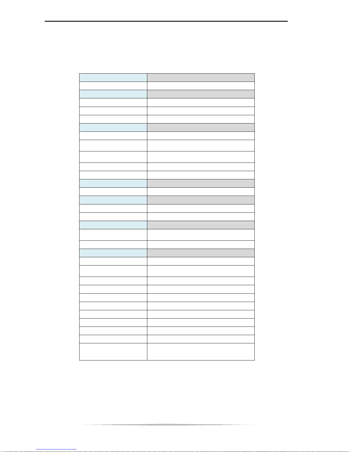
4 UNIT DESCRIPTION
4.1 Front panel legend
The following table refers to Figure 4.1 which shows the keyboard and the
main parts on the NHT310 base unit front panel.
Some keys have a second function, indicated in blue, which can be enabled
by pushing the middle button SHIFT in advance.
Fig. 4.1 – Front view
1
2
3
4
5
6
7
8
9
10
11
12
13
14
15
16
Page 15

NHT310 4. Unit description
11
Item
Name Function
1
GPS Antenna
2
Probes Input connector
3
Battery charge input
4
Backlit display
5
Temperature sensor
6
MODE key
UNIT: changes the field measurement unit.
Pressing the button for 10 seconds
it is possible to
change the temperature unit from °C to °F and vice
versa.
AXES: visualizza i singoli assi X, Y, Z.
7
STORE key
SINGL: storing a single measuring value. If
pressed for more than 2 seconds, initiates a
countdown sequence before starting the store. If
pressed for more than 4 seconds enables/disables
the spatial average mode.
MONIT: start a monitoring sequence.
8
LIGHT key
TEMP: Temporary backlight of 10 s.
CONT: Continuous backlight.
9
SHIFT key
SHIFT: Enables all blue defined functions.
Page 16

NHT310 4. Unit description
12
10
POWER key
ON / OFF: Switching the device on / off.
11
GPS key
ON / OFF: enables / disables the GPS receiver.
12
Blue LED indicating battery recharge.
13
RESET key
AVG: reset of time average value.
If pressed for
more than 10 seconds performs a reset of the
instrument, reinitializing all parame
ters and
deleting all stored data.
MAX: reset of the MAX measured value.
14
ALARM key
ON / OFF: enables / disables the acoustic alarm
of
exposure threshold exceeded.
15
FILTER key
ON / OFF: Enables / disables a
filter for low
frequency probes.
With the magneto-
static probes 10H or 33H, if the 3
axis display mode (X,Y,Z) is activated, the field
direction, positive or negative are also displayed.
16
¼-
inch threaded hole for tripods or brackets
mounts
Tab. 4.1 – Front panel and keyboard legend
Page 17

NHT310 4. Unit description
13
4.2 Connectors and interfaces legend
The tables below refer to connectors and interfaces available on the back and
at the top of the base unit.
Fig. 4.2 – Rear View
Item
Name Function
1 FIBER
Fiber optic cable interface for connection to a
remote PC/Tablet
Tab. 4.2 – Rear interfaces
1
Page 18

NHT310 4. Unit description
14
Fig. 4.3 – Top view
Item
Name Function
1
BARREL JACK Battery charge input
2
LEMO Probes Input connector
3
GPS GPS Antenna
Tab. 4.3 – Top interfaces
1
3
2
Page 19

5 PREPARATION FOR USE
5.1 Unpacking
As soon as the instrument arrives at its destination, please carefully check the
packages to verify possible damages caused by shipment. If any damage is
found, inform Microrad immediately. It is recommended to keep the original
packages for a future return shipment due to, for instance, repairing or
resetting.
5.2 Storage
After the material contained in the packages has been inspected and it has
been verified for damages, it should be stored in its original packing until the
time of use. The storage deposit must be well protected and free from
humidity. If the instrument should be kept in storage for a long time, it is
advisable to insert hygroscopic substances (such as silicon gel salts) in the
package.
5.3 Connecting the probes
The probe is equipped with a LEMO “Push/Pull” connector. To connect it to the
NHT310 unit, push the probe plug straight down into the probe socket until it
clicks into place (the red mark on the probe plug must point towards the red
mark on the unit socket).
To disconnect the probe, slide the sleeve on the probe plug upwards and pull
the probe upwards to remove it.
PROBE PLUG
Fig. 5.1
WA
RNING: TO REMOVE DO NOT TURN THE PROBE !
SLIDE THE SLEEVE ON THE PROBE PLUG UPWARDS AND PULL THE PROBE
UPWARDS TO REMOVE IT.
Page 20

NHT310 5. Preparation for use
16
5.4 Power supply
NHT310 operates both with NiMh rechargeable batteries (supplied) and with
alkaline dry batteries (4 x AA stylus). The battery charger delivered with the
instrument can be used to charge the rechargeable batteries supplied.
During the battery recharge cycle, the instrument can not be used for
measurements.
The batteries are usually delivered pre-charged, but they need a complete
charge before the first use. The full recharging time, very close to 100%, is
about 4 hours.
WARNING
Never connect the battery charger if dry batteries are installed!
This procedure can cause significant damage to the instrument!
Failure to do so will cause the warranty being declined!
During normal operation, the battery charge status is always displayed at the
top right of the screen.
Fig. 5.2
During the batteries charging cycle, the blue LED lights up.
Fig. 5.3
Page 21

NHT310 5. Preparation for use
17
5.4.1 Battery autonomy
The battery discharge time is longer than 72 hours of continuous operation
(with backlight turned off and no active GPS).
The discharge time of alkaline dry batteries may also be longer than that of
rechargeable batteries.
WARNING
Never use rechargeable batteries other than those supplied with the base unit.
Also, the use of a battery charger other than the one supplied may damage
the batteries and the instrument itself.
5.4.2 Battery replacement
The battery compartment is located on the instrument back (see Fig. 5.4). The
replacement procedure is described below.
Fig. 5.4
1. Switch the instrument off and disconnect it from the battery charger.
2. Open the battery compartment on the back of the instrument using an
appropriate screwdriver.
3. Remove old batteries and dispose of them in accordance with the waste
regulations in force in the country.
4. Insert the new batteries paying attention to the direction indicated in the
compartment.
5. Close the compartment.
Page 22

6 OPERATION
6.1 Base unit switching on
Press [POWER ON] key (Tab. 4.1).
The instrument starts an auto test tool and simultaneously displays instrument
information.
Fig. 6.1 shows the first screen displayed at power up and reports the
identification data of the instrument for a few seconds.
Fig. 6.1
1 – P/N : instrument identification code.
2 – S/N : instrument serial number
3 – Prd : instrument production date
4 – Fw : instrument firmware version
Fig. 6.2 shows the second screen displayed after the power up, reporting
memory status information and the setting of some parameters.
Fig. 6.2
1
2
3
4
5
6
7
8
Page 23

NHT310 6. Operation
19
5 – Snaps. number of single measurements stored in the NHT310 memory.
6 – Monit. Residual recording time for the monitoring function, calculated
taking into account the current sampling interval set (Tsamp).
.
7 – Tsamp. sampling interval used during monitoring.
8 – Tavg. time window width for moving average (AVG).
After the power up information sequence, if a probe is already connected to
the instrument, the following information are displayed (see fig 6.3).
The same information is also displayed for a few seconds whenever a probe is
inserted in the instrument.
Fig. 6.3
9 – P/N: probe identification code.
10 – S/N: probe serial number.
11 – Prd: probe production date.
12 – Cal. Probe calibration date.
13 – Typ. Probe frequency range.
If no probe is inserted or if the probe is removed, the typical screen shown in
Fig. 6.4 is displayed.
9
10
11
12
13
Page 24

NHT310 6. Operation
20
Fig. 6.4
6.2 Main measuring display screen
After the power on operation and probe detection and calibration is completed,
the main measure screen appears together with all the other report elements
which are also highlighted as shown in figure 6.5.
Fig. 6.5
1 – Measurement unit. As a default, the instrument indicates the typical
measurement unit of the connected probe (V/m for E probes, µT for B probes,
A/m for radiofrequency H probes and mT for static H probes). Pressing the
[MODE UNIT] key the measurement unit can assume one of the following
value: V/m, A/m, W/m², mW/cm². The instrument automatically calculates
conversion by applying specific algorithms.
This feature is particularly useful when measuring a plane wave (far field, ie
when the distance from the source is greater that 2d²/ λ, where λ is the
measured signal wave length and d is the largest linear dimension of the
source antenna), it is possible to calculate the magnetic field value (H) using
an electric field probe (E) or vice versa.
1
2
9
4
5
6
7
3
8
10
11
Page 25

NHT310 6. Operation
21
2 – Environmental temperature measured by the integrated sensor on the
front part of the unit. The temperature value shown is surely reliable when the
unit is working on a tripod and not in the user’s hand.
3 – GPS Coordinates. Localization information from the built-in GPS sensor.
Press the [GPS ON] key in order to activate the GPS sensor; at this point, if
the tool is outdoor, within a couple of minutes, geographic location coordinates
are displayed. Longitude and latitude coordinates, in the format defined in the
NMEA standard, alternate in displaying:
Latitude / Longitude = DDMM.FFC
Where the 2 digits DD are used for degrees (digits can be 3 for longitude), the
2 digits MM for minutes, and the 2 digits FF for cents of minute. C is the
cardinal direction: N (North) or S (South) for latitude, E (East) or W (West) for
longitude.
4 – Date and clock alternates on the display.
5 – Battery charge level. The residual autonomy is proportional to the
battery icon fill. When the battery is running low, the battery icon blinks.
6 – Instantaneous isotropic measured field value (ISO).
7 – AVG Value. The root mean square value on a moving time window is
displayed. Press [RESET AVG] in order to reset the value. The time window
width is factory set to 6 minutes, but the value is configurable via MicroLink
application. The AVG value is evaluated only after a period of time equal to the
length of the moving window has been completed (starting from power on,
from insertion of the probe or from the average reset).
The AVG value is continually updated (mobile media) by adding the latest
samples and removing the oldest. The average is dynamically updated
maintaining the same number of samples.
8 –MAX Value. is equal to the maximum ISO value; it displays the maximum
value measured from insertion of the probe or from last reset. This value is
updated only when a new higher amplitude value is reached. A reset from the
keyboard can be performed pressing [RESET MAX] key.
9 – ALM Level and SPT value. When the [ALARM ON] key is pressed, the
field threshold value above which an acoustic warning alarm is activated will
appear. This threshold can be set using the MicroLink software. In the same
region, the spatial average value, indicated as SPT, is also alternately
displayed.
10 – Filter. If the [FILTER ON] key is pressed and a low frequency probe (ie
probe 10B, probe 11E) is connected, the LPF indicator is displayed and a
Page 26

NHT310 6. Operation
22
second order low pass filter (40 dB / decade) with 1kHz cutting frequency is
enabled. Its use is useful for analyzing 50Hz sources with their main
harmonics, cutting off the influence of higher frequency sources. Figure 6.6
shows the typical filter response diagram.
Fig. 6.6
In the particular case of static field probes (eg 20H, 30H), the filter is a firstorder high pass filter (20 dB / decade) with a cutting frequency of about
1.5Hz. In this case, the HPF indicator appears on the screen of the NHT310.
This filter cuts the continuous component of the field and can be useful in
order to discriminate only static components from the others at higher
frequencies.
11 – SHIFT state indicator: for the ability to activate a blue function on the
keyboard; it is activated or deactivated via the SHIFT key.
12 – X, Y, Z. Figure 6.7 shows a screen display of the 3 orthogonal
components of the ISO field which has been selected. These values take the
place of AVG, MAX and ALM indicators when the [MODE AXES] key is
pressed.
Fig. 6.7
12
Page 27

NHT310 6. Operation
23
6.3 Recording measured value
The user can record the measured values using two different methods:
• Manual storing of the single measured value (single storing)
• Automatic storing of a measurement sequence (monitoring).
The instrument reserves two different memory spaces for the two recording
modes.
Space available in the memory for single storing: 432 measurements
Space available for monitoring sequences: 21’504 measurements.
6.3.1 Single storing
Each time the user makes preliminary measurements or he wants to store data
displayed on the screen, he has to simply press the [STORE SINGLE] key.
Every time the key is pressed, a measured value with relevant data displayed
on the screen (ISO value, X, Y, Z, time, date, GPS coordinates and time if
activated, temperature, MAX value, AVG value if available, connected probe
data) is stored in the memory.
During data storing the display shows the message as in Fig. 6.8; it informs the
user about number of stored values vs total available (432 single stores).
Fig. 6.8
A delay can be introduced when storing data: depress the [STORE SINGLE]
key for at least 2 seconds before releasing it and the countdown starts. This
feature is useful in order to allow the operator to move away from the device
and avoid disturbing the electromagnetic field before storing takes place. The
delay can be set via the MicroLink software and is the same parameter that
sets the delay for monitoring.
Page 28
NHT310 6. Operation
24
6.3.2 Monitoring
The instrument is able to carry out continuous tracking activity over time:
practically it performs a sequence of single stores, all spaced from the same
time delay.
The time interval between a sample storing and the next (sampling step) is by
default 5 seconds but it can be reconfigured by the user using the MicroLink
software.
A sample corresponds to the three values X, Y, Z. Additionally, the temperature
and the initial GPS position are also stored if available.
GPS sensor and display backlight are switched off during monitoring to
increase the batteries autonomy.
The instrument can store in up to 8 different data acquisition sequences for
electromagnetic fields long-term monitoring. The maximum limit of samples for
all sequences is 21,504 samples.
The operator can start the monitoring sequence by simply pressing the
[STORE MONIT] key.
The instrument will start a countdown of 15 seconds (it’s a default value that
can be reconfigured using the MicroLink software) before the acquisitions
start, to allow the user to move away from the instrument installed on a tripod
and thus avoid any possible disturbance of the measurement.
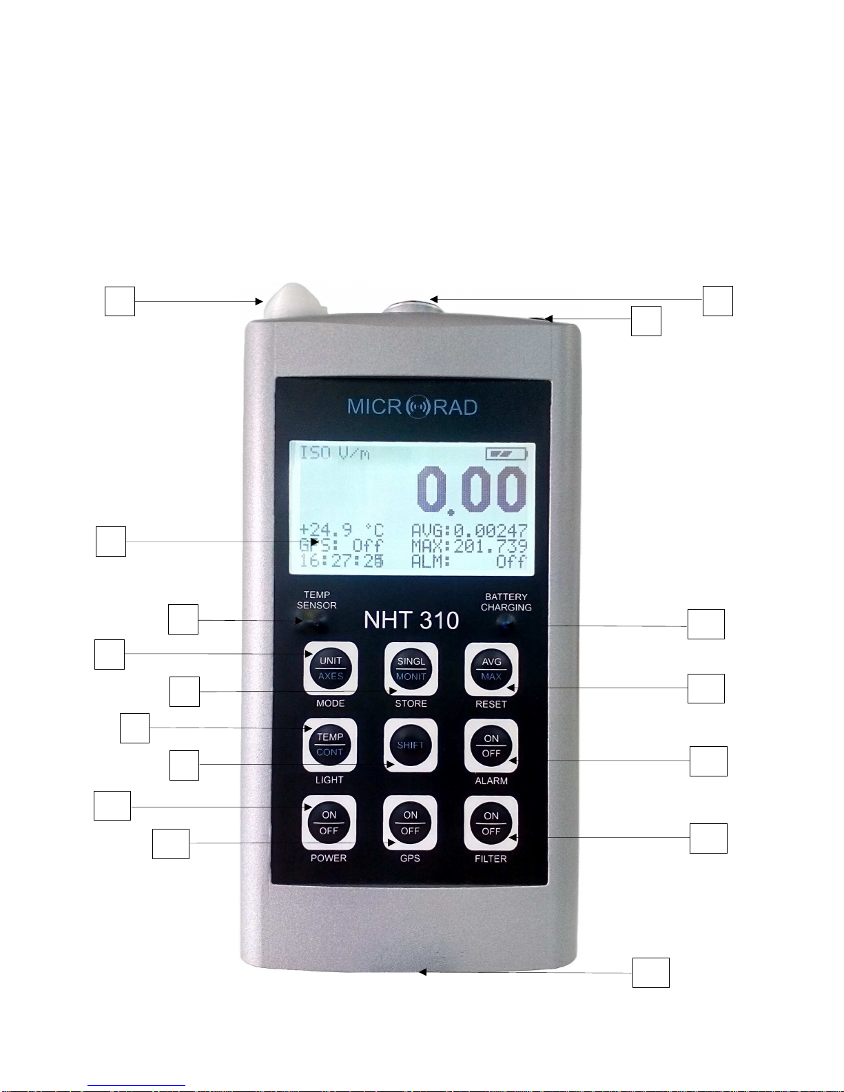
During countdown (Fig. 6.9), the current tracking number, from 1 to 8, is
displayed.
During countdown the sequence can be aborted simply by pressing any key.
Fig. 6.9
Once the monitoring sequence has started, the display will show a screen
indicating battery life, in-progress monitoring number from 1 to 8, sampling
rate, time since the monitoring start and total monitoring memory fill bar (Fig.
6.10).
An empty bar indicates that the memory available for the 21,504 samples is
completely free (no monitoring is present in memory).
Page 29

NHT310 6. Operation
25
Fig. 6.10
The measurement unit and the instantaneous isotropic value of the field (ISO)
are always displayed underneath the bar.
To stop the monitoring before the memory space is exhausted, simply press
any key on the instrument.
When there are 8 monitoring sequences or 21’504 samples already stored in
the NHT310, if a new acquisition sequence is attempted, the display shows a
full memory warning (MEMORY FULL) and the monitoring is aborted.
In order to continue monitoring activity, data must be downloaded and delete
from the device.
Monitoring start and stop can be also set from remote through MicroLink
software, by setting start time and stop time. When a monitoring activity has
been set, the * symbol blinks on instantaneous value left. Once the start time
is reached, the symbol disappears and the monitoring starts automatically for
the expected duration.
6.4 Measurement download and display
All measured values, stored in NHT310 memory, can be downloaded to an
external PC/Tablet via fiber optic connection and USB adapter. This data can
then be viewed, processed and analyzed using the MicroLink software.
6.5 Spatial Average Mode
Depressing the [STORE SINGLE] key for more than 4 seconds, the
instrument enters into the spatial average mode. The same procedure is also
applicable to exit spatial average mode and return to standard mode.
This mode is signalled by the MODE SPATIAL AVERAGE text that replaces
the section normally reserved for temperature, GPS, date and time on the
display (Fig.6.11).
In this mode, user can save single values by pressing [STORE SINGLE] (as
described in Section 6.3.1) and can visualize on the display a SPT window
showing the root mean square value calculated on the N captured samples.
Page 30

NHT310 6. Operation
26
This function can be useful to quickly obtain an average value in space when
two or more values are captured in different spatial points.
Fig. 6.11
Note that the SPT value is also displayed in the standard operating mode,
alternating with the ALM alarm threshold display. Additionally, the SPT average
value is maintained even after the instrument is switched off, and it is reset
only when the instrument enters into spatial average mode.
6.6 Alert levels
The NHT310 features a function which alerts the user by means of an acoustic
signal which indicates that the measured field exceeds a user configurable
threshold inserted via the MicroLink application; this function is enabled by
pressing the [ALARM ON] key.
As well as having this user configurable function, the instrument also alerts the
operator when the maximum field value measured by the probe has been
exceeded by 95%. This warning is provided by the letter E which appears
beside the ISO field (Fig. 6.12) accompanied by an acoustic signal. The letter
E appears near the isotropic value and near axis which has surpassed this
threshold, as long as the display of the single components has been selected.
Fig. 6.12
Page 31

NHT310 6. Operation
27
In the case where the field is so strong that it surpassed the probe range, then
the message OVER-RANGE (Fig. 6.13) appears on the screen in place of the
isotropic value; the message is always coupled with an acoustic signal.
Fig. 6.13
6.7 Factory reset
To perform a reset on NHT310 unit, press the [RESET AVG] key and hold it for
10 seconds. The system restarts by performing a general reset.
This action will erase all measurement data and will restore all NHT310
parameters to factory default.
Page 32

7 MICROLINK SOFTWARE
7.1 Description
The MicroLink software, supplied with the NHT310, has mainly three functions.
The first is to allow the setting of the instrument parameters, relating to the
moving average, the monitors, the alarm thresholds and the clock.
The second is to allow download on a PC of all data stored in the NHT310
memory and its graphical and tabular display on PC screen, in order to include
in a measurement report. Data can also be exported in Microsoft Excel™
compatible format.
The third function is to manage the NHT310 from a remote PC using the fiber
optic cable. This mode is indicated for measurements with the instrument
installed on a tripod, in order to constantly monitor the field but avoiding the
influence of the user's presence. In this mode, user can also change the
setting of the NHT310 parameters.
7.2 Software installation
MicroLink software is compatible with Windows XP, Vista, 7, 8, 10 operating
systems, both 32 and 64 bits. The installation file can be downloaded from the
Microrad website (www.microrad.it) within the software download page.
Together with the application, the Optical / USB adapter driver is also installed,
enabling automatic adapter recognition each time it is connected to the PC.
7.3 Software main screen
Fig. 7.1
Page 33

NHT310 7. MicroLink software
29
The program functions can be opened from the upper toolbar menu as follows:
File - [Open] [Save] [Properties] [Exit]
Meter - [Download] [Settings] [Remoting] [Fw Update]
Data - [Export] [Units] [Print]
Help - [Contents] [About]
For simplicity, all the functions listed above can be accessed directly via the
icons located immediately under the menu bar (except the Fw Update and Exit
functions).
When the NHT310 is not connected to the PC, a No Device message appears
in the right bottom of the screen.
Once the instrument is connected, as soon as the user interacts with it with
some command or opens the MicroLink application, the name NHT310
appears in the same window, meaning that the instrument has been identified
and communicates.
As long as user do not recall a file that has already been saved on the PC, the
No File Loaded message appears in the lower left of the screen.
When a measurement file is selected and opened, its name and path appear
in the same window.
7.4 Functions
Save
– Saves a new measurement file on a PC's mass
unit.
Open
– Searching and opening a measurement file
previously saved in the PC.
Properties
– Displaying data of the NHT310 instrument
connected.
Download
– Transfers data stored on the NHT310 to the
PC.
Settings
– Allows the user to set configuration
parameters of the NHT310.
Page 34

NHT310 7. MicroLink software
30
7.5 NHT310 parameters setting (Settings)
By clicking on the [Settings] icon, user can access the configuration screen
(Fig.7.2) for some parameters of the NHT310. These parameters are:
• RMS Average : time interval for AVG average calculation
• Monitoring : start / stop time and sampling interval
• Alarm Level: threshold level for acoustic alarm
• Date & Clock: Date and time of NHT310
Remoting
– Remote management of the NHT310 from
PC via fiber optic connection.
Export
– Exports in tabular format (Excel compatible) all
the acquisition data.
Units
– Selecting the default measurement unit for the
electric and magnetic fields, and for temperature.
Print
– Prints the acquisition data.
Contents
– Link to the user's manual via Internet
Abo
ut
– Information regarding the software version
installed.
Page 35

NHT310 7. MicroLink software
31
Fig. 7.2
The possible settings from this panel are illustrated below.
Fig. 7.3
Fig. 7.4
RMS Settings
User can set the time interval to calculate the AVG (time
average) value in the range from 1 second to 192
minutes. Default value is 6 minutes as per international
regulations.
This configuration is useful for high frequency
measurements.
Monitoring Settings
User can configure:
• time interval between a sample and the
next (Sampling Time, from 1 to 30
seconds);
• start delay time (Start Delay);
• enable or disable the scheduled
monitoring (Enable);
• date and time for monitoring start (Start
Time);
• date and time for monitoring stop (Stop
Time).
Page 36

NHT310 7. MicroLink software
32
Fig. 7.5
Fig. 7.6
7.6 Download data from NHT310 (Download)
After connecting the NHT310 to the PC through the supplied optical cable and
converter, click on the [Download] icon.
Data transfer starts and a progress bar appears during the process (Fig.7.7).
When download is complete, user can to save measurements on the PC. This
action is not necessary at this stage and can also be done at a later time by
clicking on the [Save] command.
It is also required if user wants to delete the data from the NHT310.
Alarm Settings
Allows the user to configure the alarm threshold for high
field.
• High Frequency Probe: level and measurement
unit for use with high frequency electric (E) or
magnetic (H) probe;
• Low Frequency Magnetic Probe: level and
measurement unit for use with static or low
frequency magnetic probe;
• Low Frequency Electric Probe: level and
measurement unit for use with low frequency
electric probe.
Meter Clock Settings
Allows the user to configure the date and time of the
NHT310.
Page 37

NHT310 7. MicroLink software
33
Fig. 7.7
Data saved to files (.uR extension) can also be recalled via the [Open]
command.
After download or after opening a file, a screen is displayed that allows
selection between SnapShots, Monitoring, Plot.
7.6.1 SnapShots panel
SnapShots are measures taken in punctual mode.
Fig. 7.8
Page 38

NHT310 7. MicroLink software
34
Each single measurement (snapshot) is represented by a line in a table which
contains the following information:
• Progressive number (from 1 to 432).
• Date and time.
• X, Y, Z instantaneous component values for the field.
• Instantaneous isotropic values of the field (ISO).
• r.m.s. moving average value (AVG) and time window width.
• Maximum isotropic value (MAX) with associated date and time.
• Temperature
• Filter on/off status (only for low-frequency probes).
• The model of the probe with which the measurement was taken (with a
click above this field a window will appear with all the details of the
probe).
• GPS status: if the GPS is active and locked on to a satellite during the
measurement activity, a Lock message appears. By clicking on it the
user can access to the GPS coordinates and time and to the map view
as explained in paragraph 7.9.
From this screen user can also get a Spatial AVG value by simply pointing two
or more of the available AVG values.
This is very useful, for example, when measurements have been made with a
tripod mounted NHT310 unit at different heights as suggested by some
guidelines. Obviously, user can highlight non-consecutive measurements by
clicking on the mouse while depressing [CTRL] key on PC. The value is
displayed in the Spatial Avg field.
Note that, unlike the spatial average that NHT310 calculates in space mode
(par.6.5), which is a quadratic average on instantaneous values, this is a
quadratic average that MicroLink software calculates considering the values
already mediated over time by the instrument (AVG).
7.6.2 Monitoring panel
Table below (fig.7.9) lists all samples acquired in monitoring mode. Each row
corresponds to a stored sample.
Page 39

NHT310 7. MicroLink software
35
Fig. 7.9
Eight separate monitoring sequences can be stored, that can be selected by
control on top left corner, under the #Monitoring tag.
The maximum number of measurements and then lines in the table is 21’504.
For each one the following information are displayed:
• Progressive number (from 1 to 21’504 if a single monitoring filled all the
NHT310 memory).
• Date and time.
• X, Y, Z instantaneous component values for the field.
• Instantaneous isotropic values of the field (ISO).
• r.m.s. moving average value (AVG) calculated using the Tavg parameter
that was selected at the time of the monitoring start, or calculated on
24h when the function Avg24h is selected.
• Temperature.
On the table top, many important information about the monitoring are
displayed:
• Date and time of start (Start) and stop (Stop).
• Sampling step used (Tsample).
• Number of samples acquired (Nsample).
• UserStop indicator, if Yes is displayed the monitoring has been stopped
manually (by tapping the instrument or pulling out the probe) and then
Page 40

NHT310 7. MicroLink software
36
the last data may be disturbed by the operator proximity. As an
alternative to manual shutdown, it is possible to stop monitoring by
remote control, setting a scheduled stop, or stop for memory depletion.
• FilterStart indicator, returns the On / Off status of the instrument low
frequency filter during monitoring.
• The Avg24h control enables a 24 hours calculation of the moving
average in the Avg column, by forcing a 24-hour Tavg. This calculation
is useful only in case of monitoring sequences lasting more than 24
hours.
• Time interval for moving average calculation set during acquisition
(Tavg).
• Minimum (Min) and maximum (Max) instantaneous isotropic value
measured.
• Moving average maximum value (AvgMax).
• Median index or middle value (Median).
Note that the AvgMax average value index is calculated only for monitoring
carried out using radio frequency probes; while the Median index is calculated
only for static or low-frequency probes.
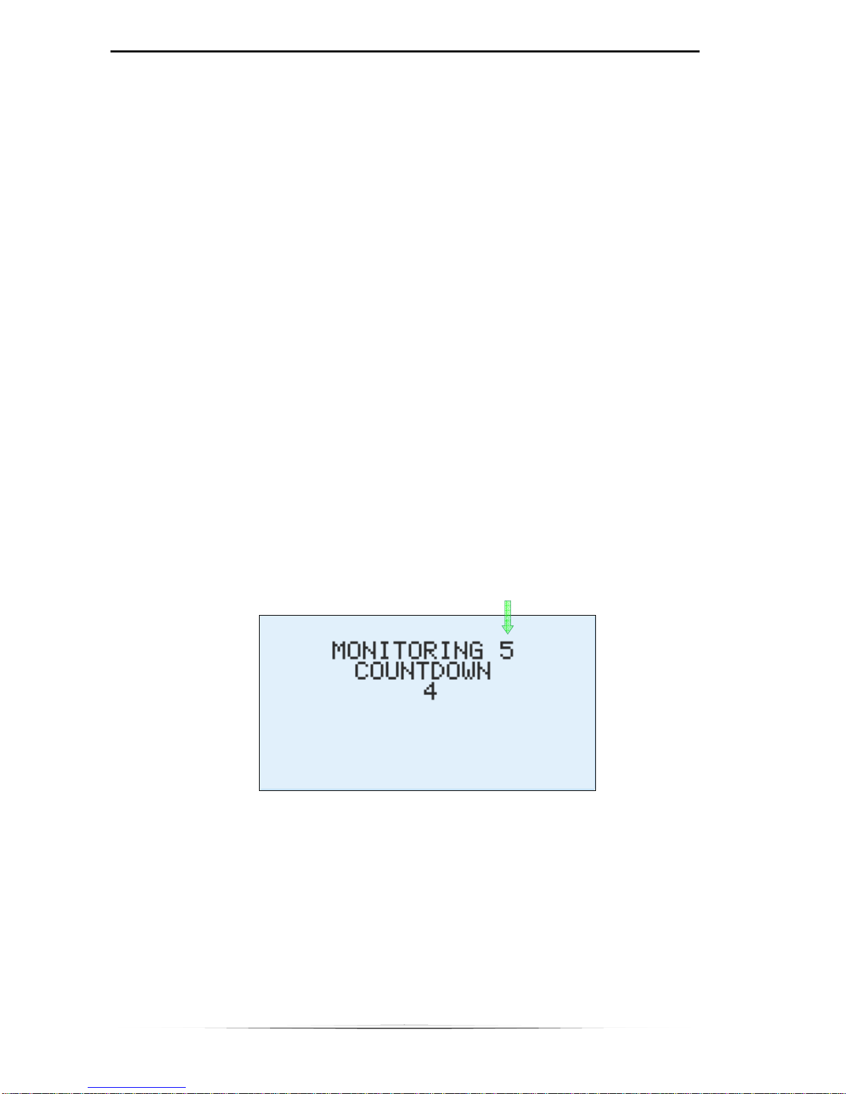
Finally, through 2 dedicated buttons, operator can access the probe data used
for monitoring and GPS information (Fig.7.10). Coordinates and GPS time
refer to the location and time at the monitoring start.
Fig. 7.10
7.6.3 Monitoring data graphic format
In this section, operator accesses the time diagram (Fig. 7.11) of the
monitoring sequence selected in the numerical display panel pressing the
control #Monitoring.
Controls displayed in the bar on the left are described below.
• Y Scale: allows to switch from the linear view [Lin] of the field values to
the logarithmic [Log] (except temperature and weighted indexes that are
always displayed on a linear scale); in the case of logarithmic display, the
Page 41

NHT310 7. MicroLink software
37
value of 0 dB is assigned to the maximum value of the isometric field;
then each point assumes a decibel value according to the relation:
E(dB) = 20 Log10 ( E / E
isomax
)
• Tracks: allows the viewing of the [ISO] instant field values, of the
individual axes [X], [Y], [Z], of the r.m.s. value [AVG], of temperature [T].
• Marker: indicators (horizontal lines) for the maximum [Max] and minimum
[min] value of each plot displayed.
• Tools : functions to zoom time dimension and to export the diagram to
bitmap or jpeg files [Export image] .
Fig. 7.11
Moving the mouse pointer over the graph values are displayed.
By highlighting (dragging the mouse with the left key depressed) parts of the
table, the corresponding portions of the diagram automatically highlight (Fig.
7.12) and vice versa.
Fig. 7.12
Page 42

NHT310 7. MicroLink software
38
As far as exporting graphics images is concerned, by clicking on the specific
icon user can access the image save window as illustrated in Fig.7.13.
Fig. 7.13
User can select the .BMP or .JPG file type and choose inverted colors in order
to save with a white background for a better print economy.
7.7 Microsoft Excel™ data export
After data download, in addition to saving them on a PC using the [Save]
button, user can export them automatically to Excel by clicking on [Export].
The window illustrated in Fig.7.14 will open, there user can select the data he
wants to export, both for SnapShot and Monitoring. The choice is between all
data, no data, only the selected data.
User can then choose to name and save a new .xls file with the selected
measurements.
Fig. 7.14
Page 43

NHT310 7. MicroLink software
39
7.8 NHT310 remote control
After switching on the NHT310 and connecting it to the PC, user can remotely
control it by clicking on the [Remoting] command.
A double window on the PC monitor will be displayed: on the left the frontal
image of the instrument is faithfully reproduced; on the right, the real-time
measure graph is displayed.
User can manage the NHT310 instrument, simply clicking on the virtual
keyboard on the PC.
Fig. 7.15
The graph displayed on the PC screen is not saved in the PC memory. To
perform any single or monitoring data acquisition, user must press the
[STORE SINGLE] or [STORE MONIT] virtual keys.
7.9 GPS and Google Maps
Localization information (latitude and longitude) from the GPS sensor are
always displayed on the instrument screen, as well as inside the virtual
instrument on the MicroLink screen.
In addition, as already seen, GPS location and UTC time are saved in the
instrument both with single acquisitions and with monitoring.
In this case, after data download to the PC, not only the GPS coordinates and
the time are recorded, but the user also has the facility to view them using
Page 44
NHT310 7. MicroLink software
40
Google Maps which indicates the positions from which the measurements
were taken.
This is done by establishing a connection between the PC and the internet
and then clicking on the [Maps] button which appears in the window as shown
in Fig. 7.16.
Fig. 7.16
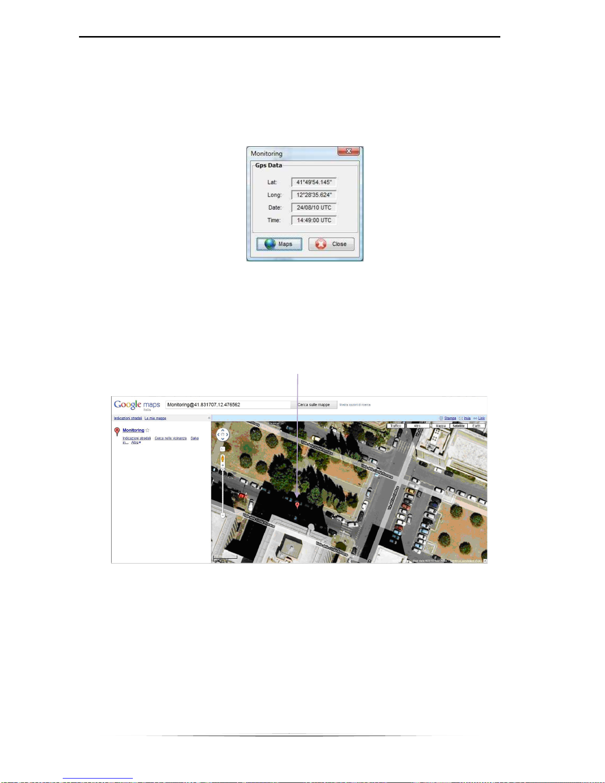
This command automatically opens Google Maps in the predefined browser of
the system and shows the position from which the measurement was taken on
the map (Fig. 7.17).
MEASUREMENT SITE
Fig. 7.17
Page 45

NHT310 7. MicroLink software
41
7.10 NHT310 firmware update
The MicroLink software is designed to allow eventual updates to the firmware
located inside the NHT310 device when they are released by the
manufacturer.
The file containing the new firmware version is recognizable through the
extension .rom and may be downloaded from the manufacturer website:
www.microrad.it.
.
To carry out an update the following procedure is used:
• Make sure the NHT310 device is switched off before connecting it to the
PC via the optical cable supplied with the kit.
• Press the [RESET AVG] key on NHT310 keyboard and, keeping this key
pressed, contemporarily press the instrument [POWER ON].
• Release [POWER ON] key but keep the [RESET AVG] key pressed until
the following message appears on the screen:
“FIRMWARE UPDATE MODE”
• Release the [RESET AVG] key.
• After the start of MicroLink software, click Meter menu and then [Fw
Update] menu.
• A window will open that allows to select .rom files on the PC's hard disk.
Select and open the file (double-click or Open key).
• The update automatically started, and It can take about 30 seconds.
At the end of the update procedure the MicroLink software sends a message
that the update procedure has been successful. The NHT310 will then reboot
automatically.
Page 46

APPENDIX A COMMUNICATION PROTOCOL
The measurements made by the instrument can also be accessed through
proprietary applications, using the fiber optic communication line and the USB
adapter.
To enable communication between the PC and the instrument USB line,
operator must first install the Virtual COM Port (VCP) driver provided by
FTDIChip; the driver allows the software to see the USB line as a normal serial
port and establish communication with UART protocol.
Driver installation is not required if a PC where Microrad MicroLink software is
already present is used.
In any case, operator should verify that the VCP option is enabled:
Device Manager (Gestione dispositivi) → Controller USB → USB Serial
Converter → Properties → Advanced
Fig. A.1 - Virtual COM Port enable
From the proprietary application, the communication port must be configured
to work with 8 bit data, no parity bit, 1 stop bit (8n1), and 921600 bps speed.
On the NHT310 instrument, the serial communication mode must be enabled
pressing the SHIFT key for about 10 seconds until a blinking 'R' appears on
the left of the ISO value. This mode remains permanently active, even after
turning the instrument off and on again. Follow the same procedure to
deactivate.
When serial data communication mode is active, the instrument operates
normally, but it continuously transmits data through fiber optic (singledirectional communication from instrument to PC).
It is no longer possible to perform storage operations (single acquisition or
monitoring) on the instrument. Furthermore, before interfacing with the
Page 47

NHT310 APPENDIX A. Communication protocol
43
software application, data serial communication mode and VCP option of the
driver must be disabled.
WARNING! In serial communication mode, the instrument optical transmitter
(Class I LED) remains active even if the fiber optic cable is not inserted;
although class I optical sources are considered safe for vision, it is advisable
however to avoid direct exposure of the eyes to the emitted light.
The instrument continuously sends data packets, with a rate of 6 packets /
measurements per second. The format is the following:
Byte#
Value
0 55h
1 99h
2 Ex 0
3 Ex 1
4 Ex 2
5 Ex 3
6 Ey 0
7 Ey 1
8 Ey 2
9 Ey 3
10 Ez 0
11 Ez 1
12 Ez 2
13 Ez 3
14 Temperature 0
15 Temperature 1
16 Temperature 2
17 Temperature 3
18 Battery level
19 Reserved
20 CheckSum L
21 CheckSum H
Tab. A.1 – Data racket format
The field and temperature values are expressed in 32 bits (corresponding to
the 4 bytes indicated in the table with indexes 0,1,2,3) with single-precision
floating point format, according to the IEEE 754 standard (IEC 60559). The
byte with index 0 is the least significant.
The measurement unit is the main one displayed with the probe connected to
the instrument.
The battery level is expressed by one byte representing the percentage (0 to
100%) of residual charge.
The 16-bit checksum, divided on bytes 20 and 21 of the packet, represents the
sum of all packet previous bytes (from byte 0 to byte 19).
 Loading...