

MICROPURE 3600 Installation & Operation Manual
©2007 Dust Free® • All rights reserved. • 213348-00 Rev. 1B 2/07
Model 3600
Ultraviolet Light System
Model 3600 #09950
GENERAL
This product is designed to help disinfect the internal surfaces of heating, ventilation, and air conditioning systems. Bacteria and viruses that are in
the air stream that passes through the system will
also be reduced. The result is an improved level
of indoor air quality for occupants and improved
system hygiene.
The MicroPure® UV system emits ultraviolet(UVC)
radiation at a frequency of 254 nanometers, which
has been proven effective in damaging the DNA of
microorganisms such as viruses, bacteria, yeast
and molds. This process either destroys the microorganism or neutralizes its ability to reproduce.
FEATURES
• Reduces or prevents mold growth on HVAC
coils, allowing them to operate at peak efficiency. Also significantly reduces bacteria,
viruses, fungi, and yeasts in the ductwork.
• High Output, long life UVC bulbs.
• Low maintenance and reduced costs.
INCLUDED INSIDE BOX
• MicroPure®ultraviolet light system
• UV bulb
• Mounting ring
• Mounting screws
• Mounting template
• Installation & operation manual
• UV warning label for duct
• Ductboard mounting ring
TOOLS REQUIRED FOR INSTALLATION
• Electric drill
• Phillips screw bit or screwdriver
• 2" drill bit or holecutter
• Eye protection
BEFORE INSTALLING
• Read all instructions carefully. Failure to do
so could damage the equipment or cause
harm to yourself or others.
• Acknowledge all warnings.
• Only qualified technicians should perform
the installation.
Installation & Operation Manual
PO Box 519
Royse City, TX 75189
PH: 1-972-635-9565
Http://www.dustfree.com
E246425
MICROPURE®MODEL 3600 INSTALLATION & OPERATION MANUAL
2
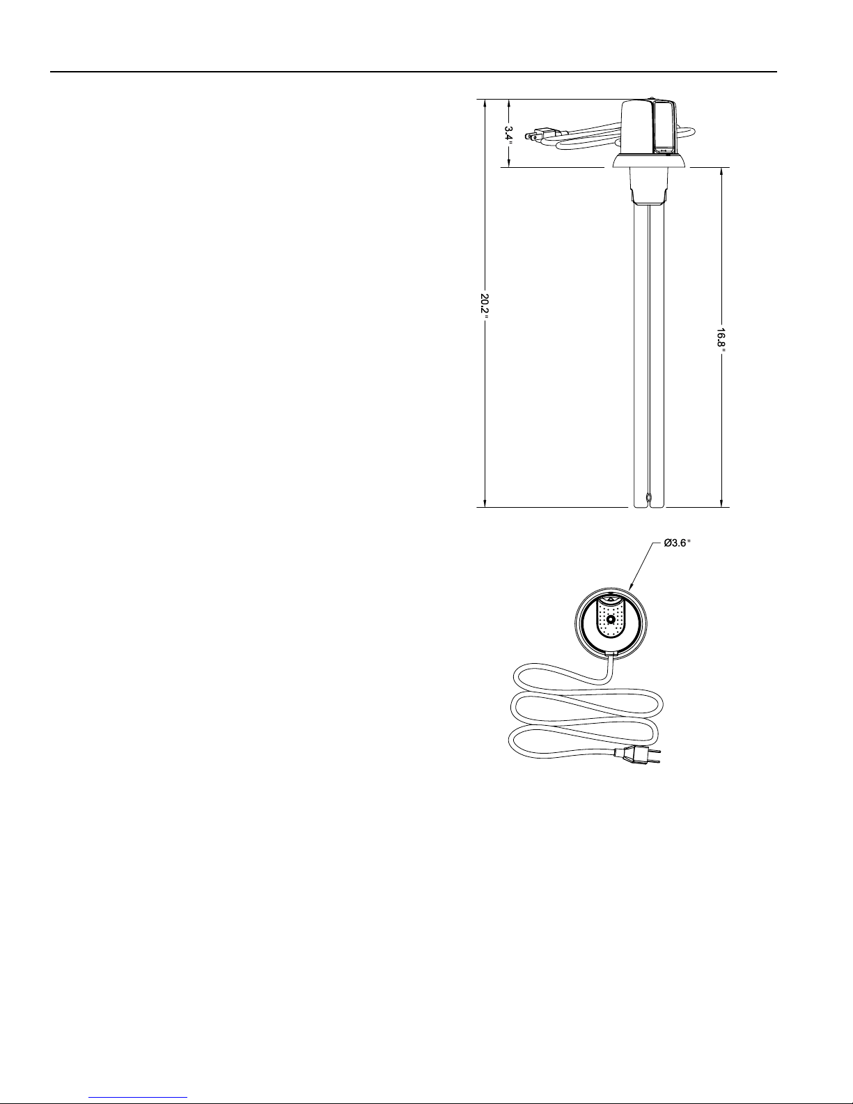
Dimensions
3.6"L x 3.6"W x 3.4"H
16" UV bulb
Weight:
Less than 2 lbs.
Electrical:
120V/60Hz. 0.85 Amps. 36 Watts. 6-ft power cord.
Listings:
Underwriters Laboratories. Category Code
ABQK (Accessories, Air Duct Mounted) UL
Standards: UL 153, UL 1598, and UL 1995.
The health aspects associated with the use of this product and its
ability to aid in disinfection of environmental air have not been investigated by UL.
U.S. Patent Nos. 5,334,347, 5,817,276, 6,245,293, 6,267,924,
6,280,686, 6,313,470, 6,627,000, 6,539,727, 6,932,494, 6,550,257.
Specifications subject to change without notice.
Fig. 1 Unit dimensions.
MICROPURE®MODEL 3600 INSTALLATION & OPERATION MANUAL
3
INSTALL THE MOUNTING RING
1. Apply the supplied mounting template to
the duct surface, centering the lamp hole on
the duct.
2. Use a holecutter to make a 2" hole in the
duct. Remove any burrs.
3. Position the mounting ring on the template,
make sure that the hole in the ring is aligning
with the cut hole in the duct and that the
locked symbol on the ring is facing up.
Note: For ductboard installations install the
ductboard ring as described before
installing the mounting ring.
4. Attach the ring to the duct by driving the
three supplied self-drilling screws into the duct
through the screw holes in the rings. Make
sure that the screw heads are fully seated in
the mounting ring and no part of the screws
protrude over the seating surface.
UVC Light Hazard.
UVC light can cause temporary or permanent loss of
vision, and sunburn. To prevent exposure, do not
install device in any applications that allows UVC
light to be visible after installation.
WARNING
SPECIAL INSTALLATION NOTES
• Do not install in closet return grille applications.
• Do not install in outdoor applications.
• Do not expose wiring or plastic parts to UV-C light.
• Do not install where UV-C light can be seen
after installation.
• Do not install beneath a humidifier.
• If the UV device is installed near an air filter or
flex duct, check with the filter or flex duct
manufacturer for UV-C resistance properties.
• If the UV device is installed on the inlet side
(return air side) of a coil, make sure that the
HVAC system is configured such that the
blower is located between the return air filter
and the inlet side (return air side) of the coil,
such as would be found in a traditional upflow, or horizontal furnace with the coil
placed after the heat exchanger.
• If the desired UV installation location is
intended to irradiate an air filter, to neutralize
the microbiological matter on the air filter
surface, such as would be found in the
return air drop of a basement application or
in the return plenum of a horizontal system
in an attic; take precautions as described in
note above, and make sure the UV fixture is
placed on the return side of the filter. DO
NOT INSTALL THE UV FIXTURE ON EITHER
SIDE OF THE FILTER IN HALL / CLOSET
RETURN AIR APPLICATIONS.
(See ATTEN-
TION! Warning sheet #212945-00).
UVC Light May Degrade Plastic and Rubber.
Shield exposed plastic drain pans, wire insulation, flex duct, or other plastic/rubber components from UVC light.
CAUTION
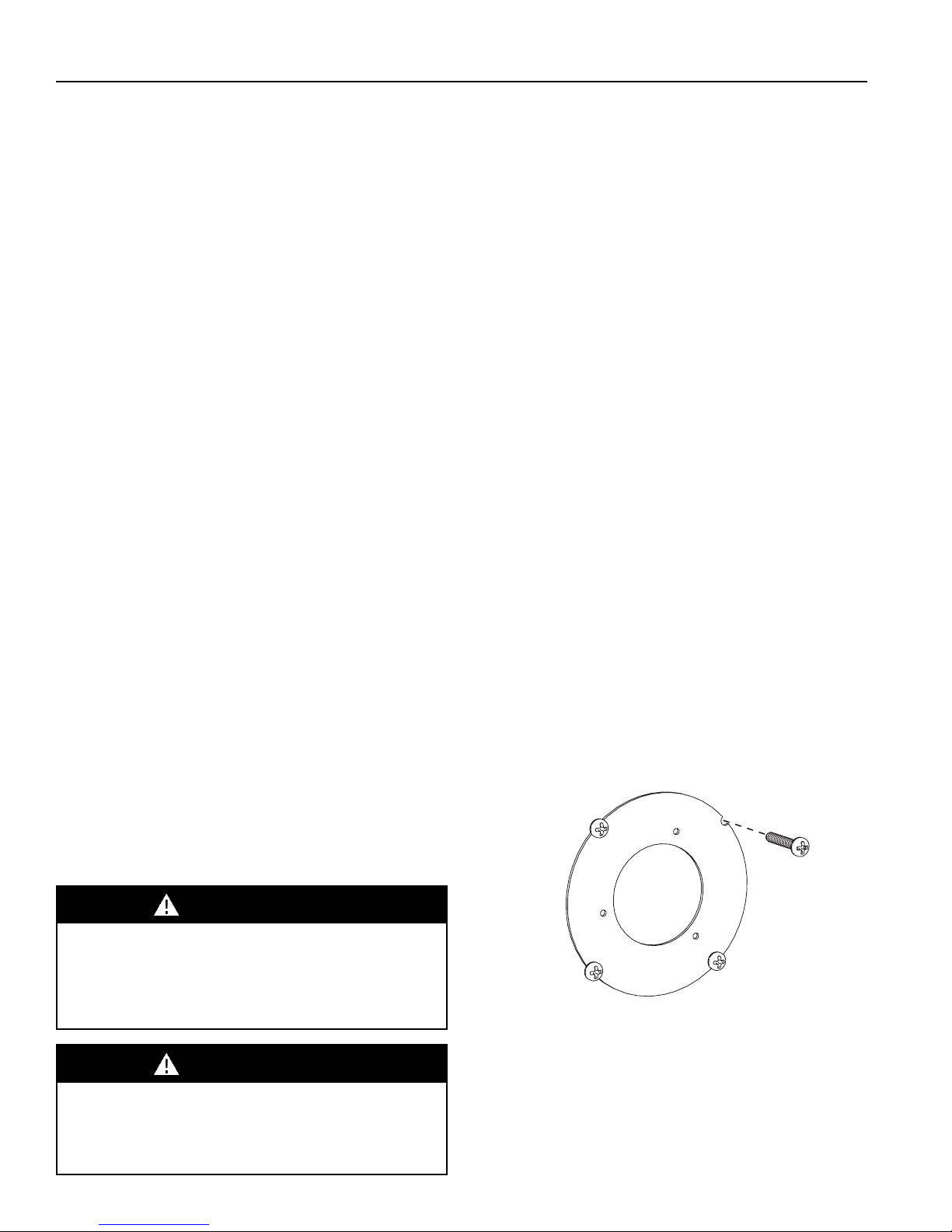
DUCTBOARD MOUNTING ONLY (Fig.2)
For ductboard installations, a ductboard
mounting ring is provided. Align the pre-drilled
holes in the ductboard ring with the screw
alignment holes on the template. Secure the
ductboard ring to the surface by screwing the
four long screws(provided) into the surface at
the notches in the ring. The head of the screw
will hold the ring in place.
Fig. 2 Installing the optional ductboard ring.
 Loading...