

Page 1
REVISION: 201301
DOC: 841615
ENGLISH
ASSEMBLY INSTRUCTION
MICROPROP DC2
DANFOSS
Page 2

2 ENGLISH
CONTENT
1.
Safety regulations 4
1.1. General 4
1.2. Check list safety 4
2.
Symbols in the assembly instruction 6
3.
Control of delivery 7
3.1. 841517 Danfoss 7
4.
Assembly 8
4.1. Area A 9
4.1.1. Dismounting original joystick 9
4.1.2. Mounting adapter 9
4.1.3. Mounting adapter 10
4.1.4. Mounting joystick 10
4.1.5. Unloading wiring 11
4.1.6. Remount 11
4.2. Area B 12
4.2.1. 841517 Danfoss 12
4.3. Area C 13
5.
Labels 14
5.1. Tiltrotator functions 14
5.2. Machine functions 15
5.1. Labels at more than one user setting 15
Page 3
3 ENGLISH
GENERAL
This instruction describes how to replace the machine joysticks to joysticks
delivered with Microprop DC2. It is important that correct joysticks are fitted in
order for the declaration of incorporation in the assembly instructions (841601,
841602 or 841603) to be valid
Aside from this assembly instruction you must read and understand the safety
information of your machine and other equipment.
WARNING!
Do no attempt to assemble, use or maintain the Microprop DC2 before you have
read and understood all information regarding the tiltrotator, optional equipment
and the machine. Be very aware of the safety information.
WARNING!
Other safety regulations are found in the assembly instruction for Microprop DC2.
Page 4
SAFETY REGULATIONS
4 ENGLISH
1. SAFETY REGULATIONS
1.1. GENERAL
It is of utmost importance that you have read and understood all warnings before
assembling and using the tiltrotator/rotator and supplied equipment. The warnings
focus on potential risks and how these are avoided. If uncertain – contact your
employer or supplier.
Remember – with good judgment and proper knowledge of the machine many
risks are sufficiently reduced. The user should therefore make time to learn how to
use the tiltrotator and the other equipment in a safe way before the machine is put
into service.
1.2. CHECK LIST SAFETY
WARNING!
Broken or damaged equipment can cause injury or damage to persons,
environment or property. Ensure that service and maintenance are done according
to recommendation.
WARNING!
Never attempt to increase the equipment’s maximum capacity by modifications not
approved by the supplier.
WARNING!
Replaced damaged and/or unreadable labels and warning signs before the
machine is used.
WARNING!
Maintenance of and repairs of the electrical system may only be made by trained
personnel.
Page 5
SAFETY REGULATIONS
5 ENGLISH
WARNING!
Risk of crushing by moving parts.
WARNING!
If uncertain of knowledge, equipment or working on safety details – contact your
supplier or engcon Sweden AB.
WARNING!
Make sure that the labels are consistent to the machine function before putting the
machine in use.
WARNING!
Assembly and calibration may only be done by an authorized work shop. Changes
in the assembly may not be made without the manufacturer’s consent.
Page 6
SYMBOLS IN THE ASSEMBLY INSTRUCTION
6 ENGLISH
2. SYMBOLS IN THE ASSEMBLY
INSTRUCTION
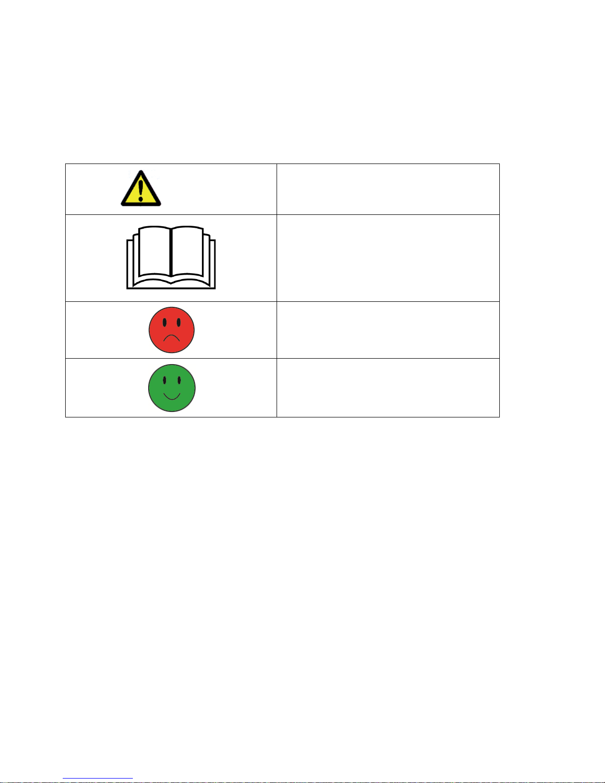
WARNING!
Risk for injury to people and/or damage to
property.
Read attached documentation for more
information.
No / incorrect measure
Yes / correct measure
Page 7
CONTROL OF DELIVERY
7 ENGLISH
3. CONTROL OF DELIVERY
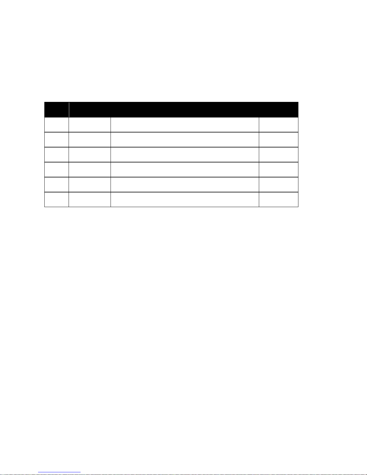
3.1. 841517 DANFOSS
Nr Article Note Amount
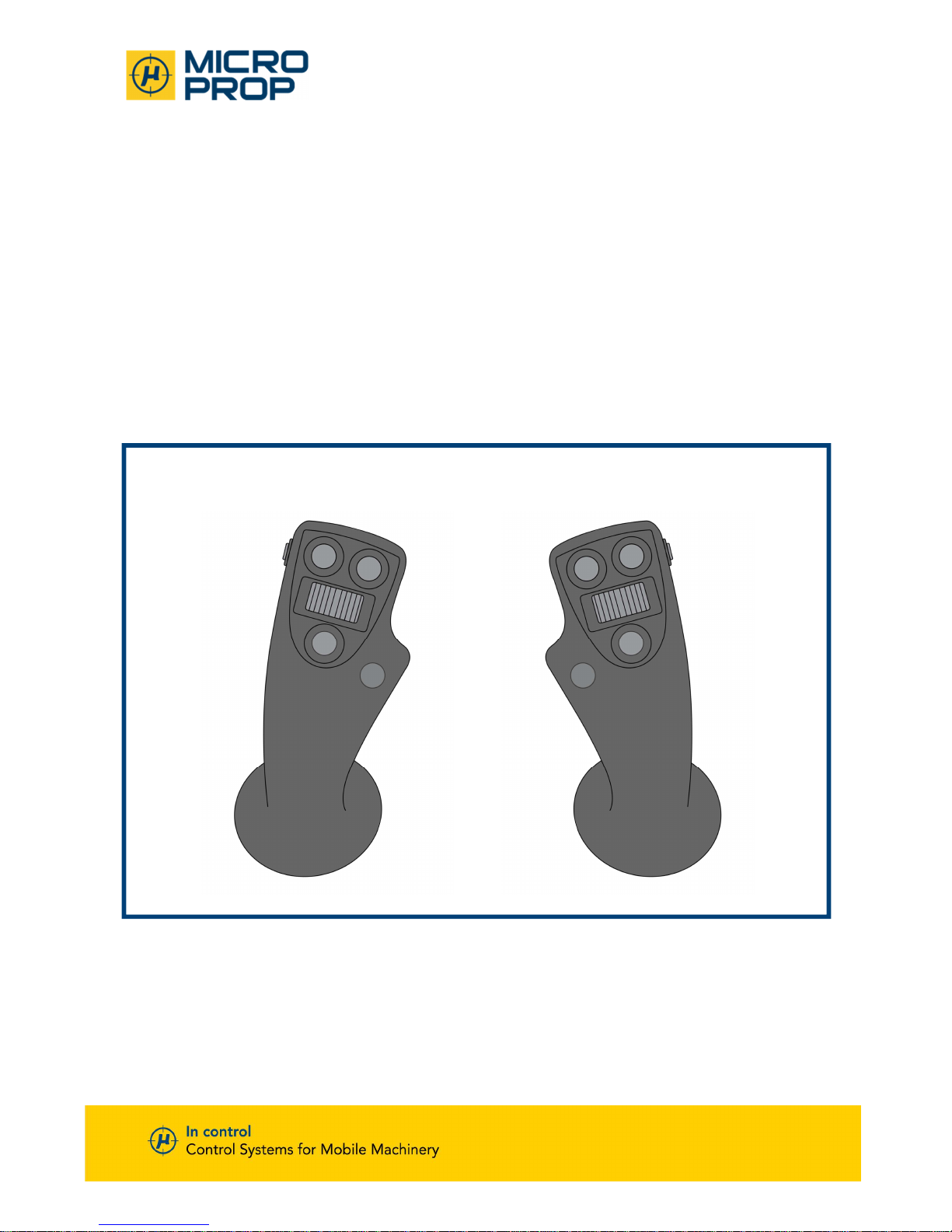
1 841271 Joystick Danfoss left 1
2 841272 Joystick Danfoss right 1
3 841190 Cable for joystick 1
5 841871 Label Danfoss 1
6 841172 Label Danfoss 1
7 841161 Label symbols machine function – see-through 1
Page 8
ASSEMBLY
8 ENGLISH
4. ASSEMBLY
Page 9
ASSEMBLY
9 ENGLISH
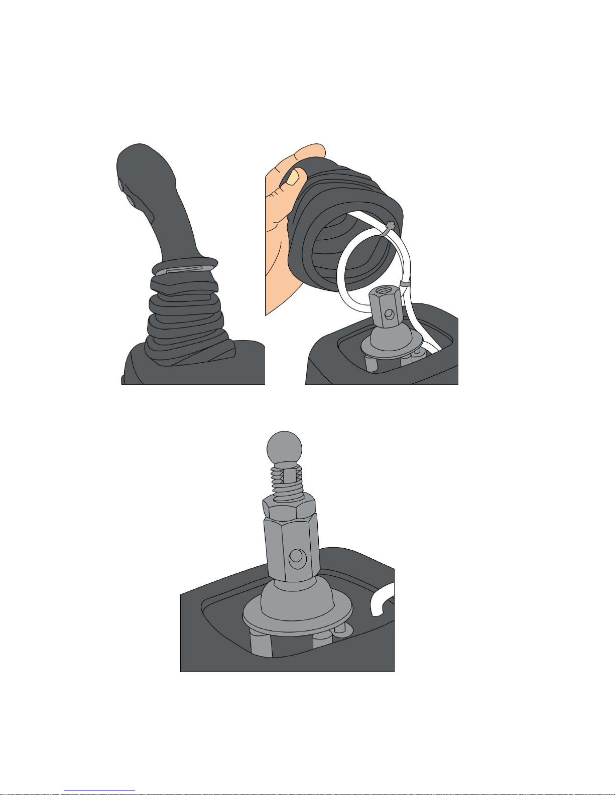
4.1. AREA A
4.1.1. Dismounting original joystick
4.1.2. Mounting adapter
Page 10
ASSEMBLY
10 ENGLISH
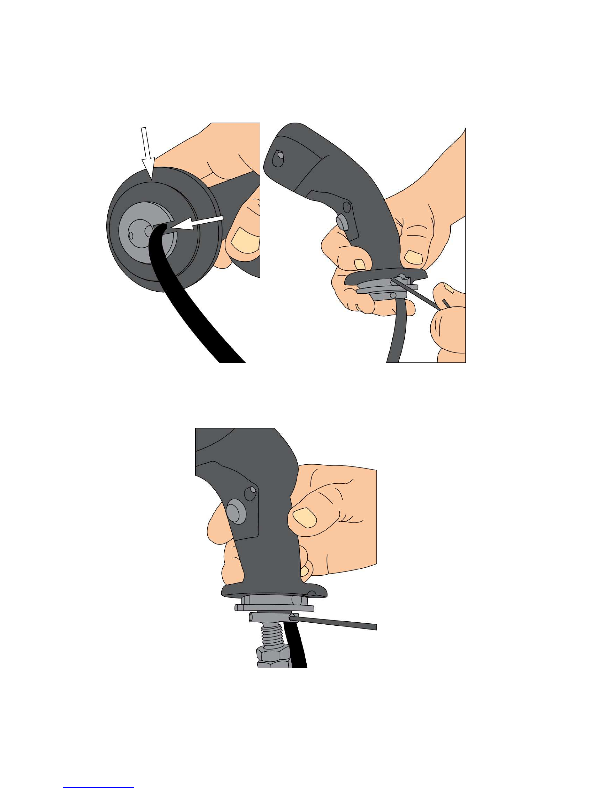
4.1.3. Mounting adapter
For L8 – see separate instruction.
4.1.4. Mounting joystick
For L8 – see separate instruction.
Page 11
ASSEMBLY
11 ENGLISH
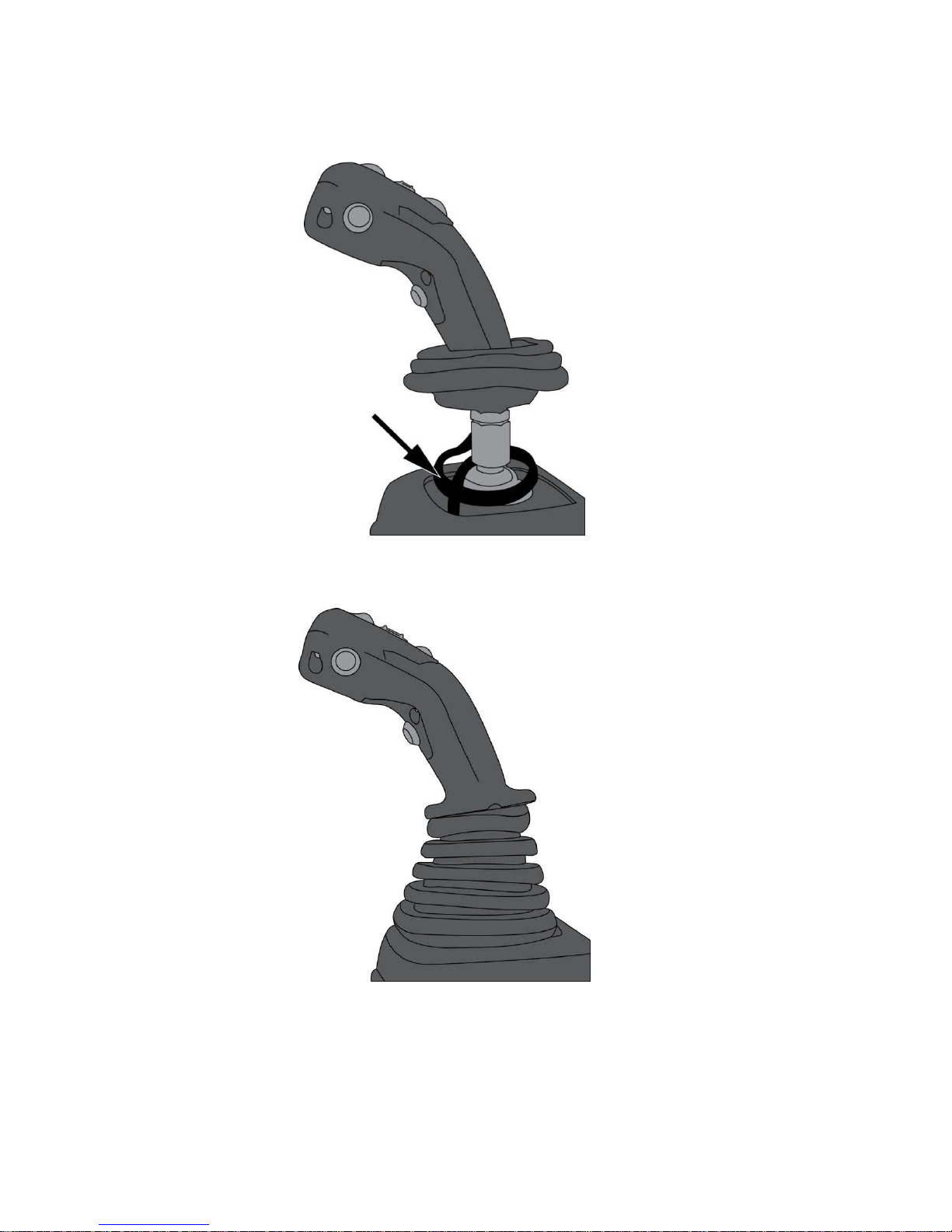
4.1.5. Unloading wiring
4.1.6. Remount
Page 12
ASSEMBLY
12 ENGLISH
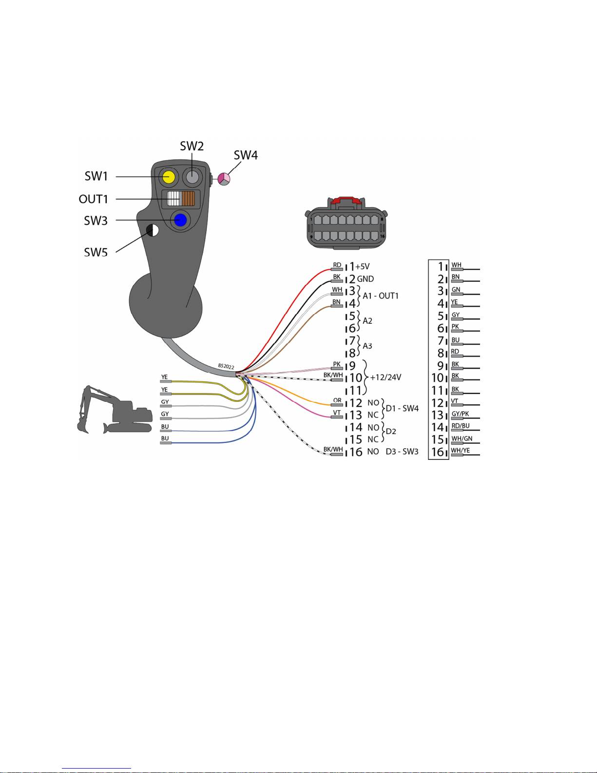
4.2. AREA B
4.2.1. 841517 Danfoss
Page 13
ASSEMBLY
13 ENGLISH
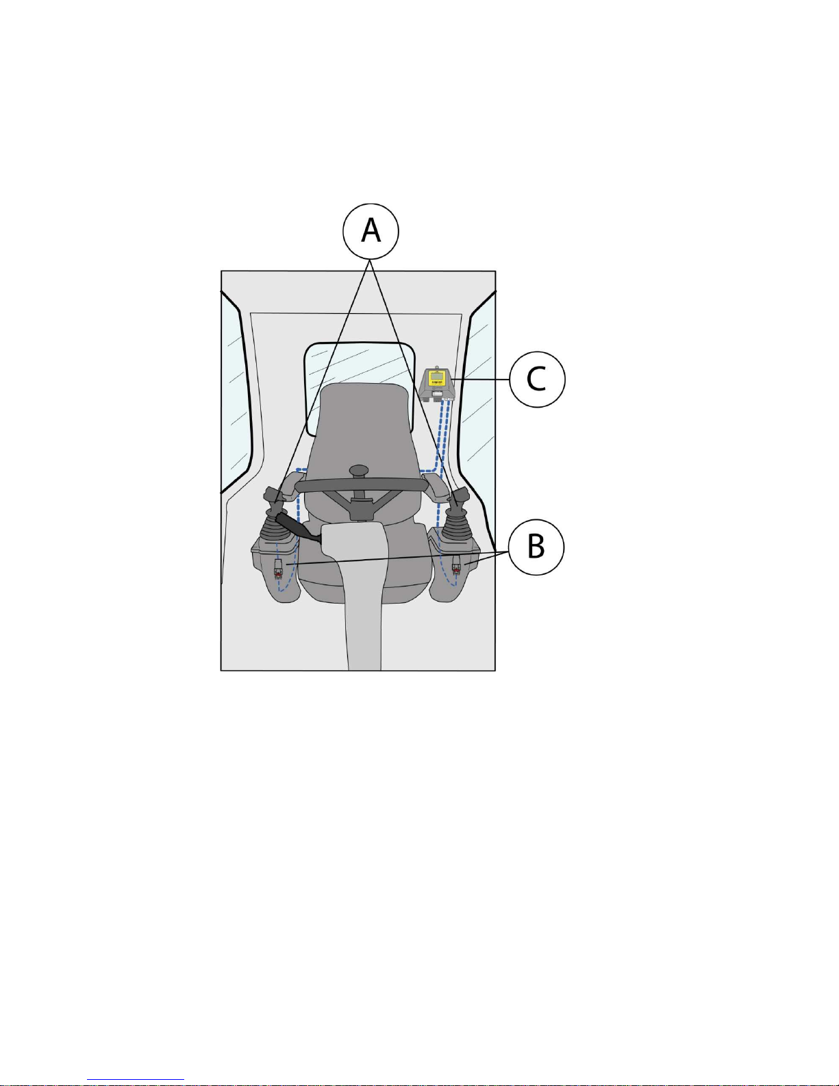
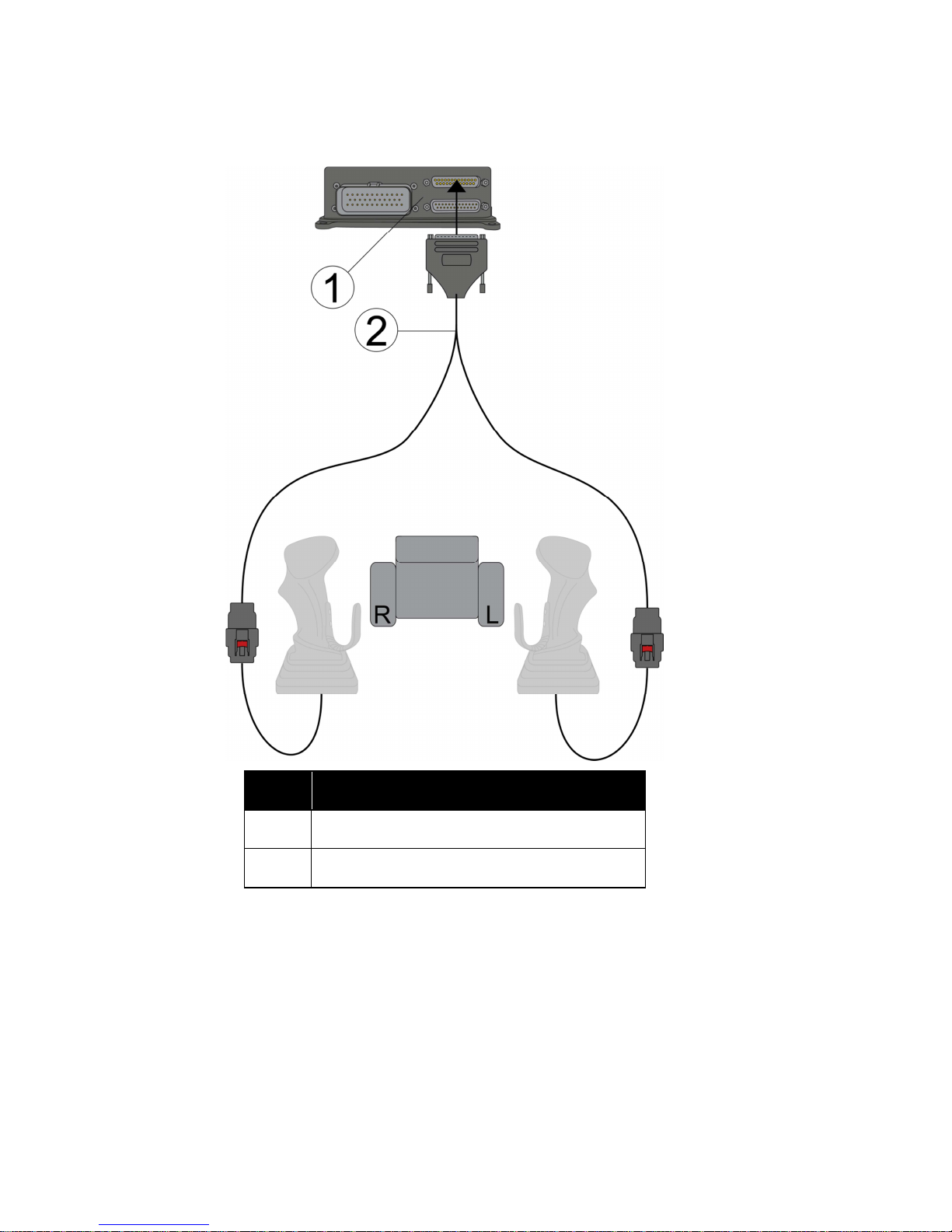
4.3. AREA C
Nr Note
1 841105
2 841190
Page 14
LABELS
14 ENGLISH
5. LABELS
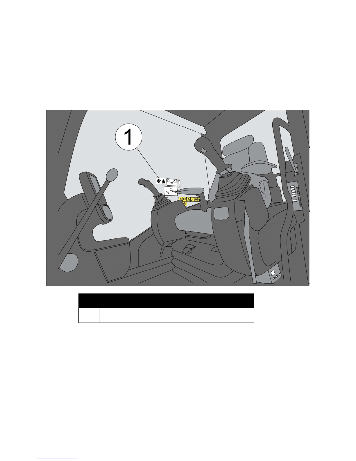
5.1. TILTROTATOR FUNCTIONS
Labels shall be plainly visible for the driver.
Pos Note
1 Labels for joysticks
Page 15

LABELS
15 ENGLISH
5.2. MACHINE FUNCTIONS
Use the paper with machine function (841161) and place the symbols on the
joystick labels so they correspond with the machine’s functions..
Note! Remember to update the machine user manual with the same information.
5.3. LABELS AT MORE THAN ONE USER SETTING
If more than one user is activated in the system, the installer must mount another
label per user. The cabin module must then be placed so that the driver can see
the display and thereby see which user that is active. The machine user manual
must also be updated with this information.
Page 16

MICROPROP AB
Industrivägen 8
SE-901 30 Umeå
Sweden
www.microprop.se
MICROPROP DC2
ADDITION TO THE MACHINE USER MANUAL.
The machine original joysticks have been replaced in this machine. The servo
controlled functions are still intact.
See labels and the user manual of Microprop DC2 for more information.
The installer is obliged to attach this information to the machine user manual.
Stamp:
Name of installer:________________________
 Loading...