


© 2012 MicroPower Technologies, Inc. 1
4350 Executive Drive, Ste. 325
San Diego, CA 92121
+1-888-854-3312
www.micropowerapp.com
Helios™
Solar Wireless IP Surveillance System
Installation Guide
Version 5.0

Helios Installation Guide
© 2012 MicroPower Technologies, Inc. 2
Table of Contents
Contacting MicroPower Customer Support 3
General Safety Precautions 3
Package Contents 4
System Overview 5
Installation Recommendations 6
I. Site Survey 6
II.
System Setup 7
III.
Mounting the MiniHub and Rugged-i camera 24
IV.
Adjusting the Camera Image 28
V. Configure the Video Management Software (VMS) 29
Helios Installation Guide
© 2012 MicroPower Technologies, Inc. 3
Contacting MicroPower Customer Support
MicroPower’s customer support strategy is through best-in-class business partners
including OEMs, distributors, systems integrators and systems vendors. If your
MicroPower product was purchased directly from a MicroPower business partner, that
partner is the first point of contact for technical support. If the business partner cannot
resolve a problem, then the partner will contact MicroPower.
Web Support: http://www.micropowerapp.com
Email Support:
help@micropowerapp.com
Phone Support Worldwide:
+1-
888-854-3312
Fax Support – Worldwide: +1-858-947-3907
General Safety Precautions
• Follow all cautions, instructions, and warnings as listed on the product and related
documentation, including electro-static discharge (ESD) recommendations, physical
handling advice and other recommendations or best practices.
• Use ESD precautions when unpacking and installing MicroPower camera and hub
products. ESD mats and grounding straps are recommended.
• Ensure that the voltage and frequency of your power source match the voltage and
frequency required by the equipment. Do not use an alternative power supply.
• Ensure that the battery size and voltage match the size and voltage required by the
equipment. Failure to do so could result in damage to the equipment and nullification
of the product warranty.
• Use only the included antennas and ancillary equipment provided with the product.
• Do not make mechanical or electrical modifications to equipment. MicroPower is not
responsible for the safety or regulatory compliance of a modified product.
• Do not omit device components that would interfere with air flow and cooling as
designed. Failure to follow these guidelines can cause overheating and affect the
reliability of your MicroPower product.
• Protect your warranty. A product which has been damaged, misused, abused or
misapplied may be determined to be out of warranty.

Helios Installation Guide
© 2012 MicroPower Technologies, Inc. 4
Package Contents
Helios Solar Wireless IP Surveillance System consists of two major devices; the MPT
2500 Rugged-I Solar Wireless IP Video Camera and the MPT 2700 Wireless Video Hub.
MPT 2500 Rugged-i™ Solar Wireless IP Video Camera
• One Directional Antenna (Combination for Narrowband and Wideband)
• Rugged-i Camera
• Camera Mounting Arm
• Mounting Hardware (IP66 Enclosure) for Camera
o 3 Hex 10 mm Philips head screws
o 2 attachment Philips screws
o 3 plastic sleeves
• Antenna Mounting Bracket
o U-Bracket
o 2 attachment screws and nuts
MPT2700 MiniHub™ Wireless Video Hub System
• One Directional Antenna
• Antenna Mounting Bracket
o U-Bracket
o 2 attachment screws and nuts
• MiniHub
• Power Cord

Helios Installation Guide
© 2012 MicroPower Technologies, Inc. 5
System Overview
MicroPower Technologies has developed a unique power and wireless technology,
TrustLinx, that is 90% lower power and 400% longer range than traditional wireless IP
video camera technology. With this proprietary and patented technology, the
MicroPower outdoor IP video cameras can be operational for five days without being
recharged by the sun and maintain 24 hour operation at 5 frames per second (fps). In
addition, TrustLinx, has a unique capability to cooperate with multiple wireless
technologies that allow the transmission of video data at a potential distance of 1/2 mile
with the highest possible video quality.
Because of this unique and proprietary technology, the MicroPower Technologies Helios
System with the MPT2500 Rugged-i Solar Wireless IP Video Camera and the MPT2700
MiniHub Wireless Video Hub work in tandem to provide a wireless IP video system
which allows for the placement of the outdoor wireless IP video camera system
practically anywhere that is needed. Thus, the MicroPower system eliminates the need
for digging trenches to connect power to outdoor IP video cameras, significantly
reducing installation time and labor costs.
Up to six (6) Rugged-i IP video cameras can be associated to each MiniHub. The
MiniHub is the data connection to a broadband Internet access point. The broadband
Internet access point can be a wireless or wired router, or a broadband modem (cable
model or ADSL modem).

Helios Installation Guide
© 2012 MicroPower Technologies, Inc. 6
Installation Recommendations
There are 5 major steps that are recommended for a successful installation. These are:
1. Site survey
2. System setup
3. Mounting MiniHub and Rugged-i camera
4. Adjust focus of the camera
5. Configure VMS
I. Site Survey
A well-thought out plan for the location of the hub and camera(s) are important steps to
ensuring that the entire system can communicate and integrate with a new or existing
video surveillance and management system. For complete guidance on performing a
quality site survey, please refer to the MicroPower collateral titled “Site Survey
Guidelines”.
For best results, a line-of-sight design between the Helios system can provide a range of
up to 1/2 mile. However, obstacles such as buildings, concrete, steel or stucco walls
and ceilings will impact the wireless performance in terms of reach and data rate
speeds. Hence, these items can affect performance and range so that the distance
between the MiniHub and Rugged-i camera may need to be reduced. If the distance
between the MiniHub and a Rugged-i camera is too far, then the video will either be
non-operational since the MiniHub and Rugged-i camera did not pair correctly, or there
will be noticeably slower frame rates. The distance between the MiniHub and a
Rugged-i camera must be a minimum of 25 feet. For further education and guidelines
on RF effects, refer to MicroPower document “A Guide to Optimizing Your RF Setup”.
Since the Rugged-i camera is powered by solar, the impact of shadows and sun direction
is an important consideration. The Rugged-i does not require direct alignment with the
sun, but it is advisable to place the camera in a location which receives an adequate
amount of sunlight throughout the day. The best time to perform a sun profile for all
cameras is during the peak hours of sunlight from 11 a.m. to 3 p.m to determine shadow
avoidance strategies.
If the Rugged-i camera is being installed in the Northern Hemisphere, ideally the panels
and cameras should be placed on the SOUTH side of a pole or facing SOUTH to minimize

Helios Installation Guide
© 2012 MicroPower Technologies, Inc. 7
shadows created by the attached pole. East and west facing cameras are acceptable but
not optimal. Avoid placing the camera on the NORTH end of a pole or facing NORTH. If
the Rugged-i camera is installed in the Southern Hemisphere, ideally the panels and
cameras should be placed on the North side of a pole or facing NORTH for minimal
shadow impact.
For more information, see the following link.
http://www.ehow.com/how_6069191_install-panel-direction-aiming-degrees.html
In addition, areas that are not recommended include:
• Indoors
• Under a roof eave
• Underneath a tree canopy or foliage which does not receive adequate sunlight
• Next to a building that will create shadows at a different part of the day
Additionally, please make sure there are minimal obstructions to the camera antennas
and that they are able to be appropriately positioned to receive and transmit data and
video to the hub.
II. System Setup
The following steps are required when performing system setup and installations.
1. Add antennae to MiniHub
2. Configure MiniHub for the final IP address desired.
3. Reboot the hub system.
4. Add camera through the web interface.
5. Add camera antennae
6. Connect the battery cables to the camera.
7. Adjust camera settings if necessary
8. Verify the pairing between the MiniHub and Rugged-I camera in a close
proximity environment.
9. View the camera connection through the web interface and Live Connection.
10. Begin mounting process of the final locations for the MiniHub and cameras.
Helios Installation Guide
© 2012 MicroPower Technologies, Inc. 8
For most systems, the pairing between the MiniHub and the Rugged-I Camera have not
been performed. If the pairing between the MiniHub and Rugged-I camera has been
performed by the factory (steps 1 – 5 have been completed), the user only need to
perform the VMS setup. Refer to the documents titled VMS setup for your specific
VMS.
During the configuration and pairing exercise, the antennas for the MiniHub and
Rugged-i Camera are required to be attached before the battery connection with the
camera is connected.
A. Accessing the MiniHub
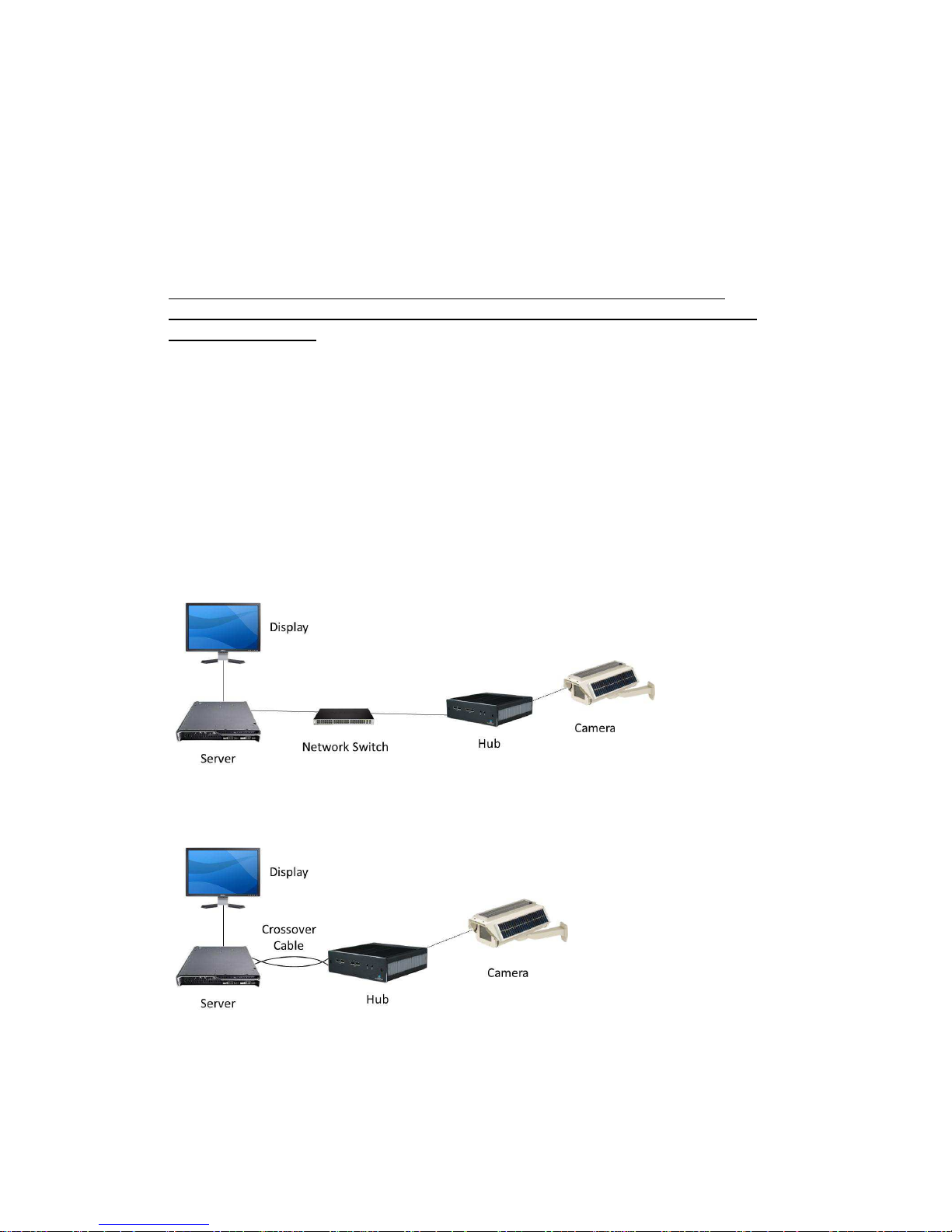
Accessing the MiniHub is similar to setting up a wireless router in the home. A display
or network console is used to directly address the MiniHub. There are two basic
topologies in which the MiniHub can be addressed. The common method for systems
which already have a sophisticated network in place is addressing the MiniHub through
a network switch. It is also possible to communicate to the MiniHub from a server
directly to the MiniHub through a crossover cable. Below are illustrations of both
topologies.
Network Switch Topology
Crossover Cable Topology
Helios Installation Guide
© 2012 MicroPower Technologies, Inc. 9
B. System Setup via the MiniHub
It is important to configure the MiniHub first, prior to pairing the MiniHub to the
Rugged-i cameras. System setup is performed through a web Interface while addressing
the MiniHub through a network console, similar to how a wireless router is configured in
a home setting.
The MiniHub must be connected to a network switch prior to configuring the MiniHub
or directly to a laptop/network server through a crossover cable. Communication to
the administration console application of the MiniHub is performed through a standard
browser via a network console. (Note: The MiniHub is a fully operational Linux server.
Any application that is loaded on to the MiniHub will nullify the MicroPower
Technologies warranty.)
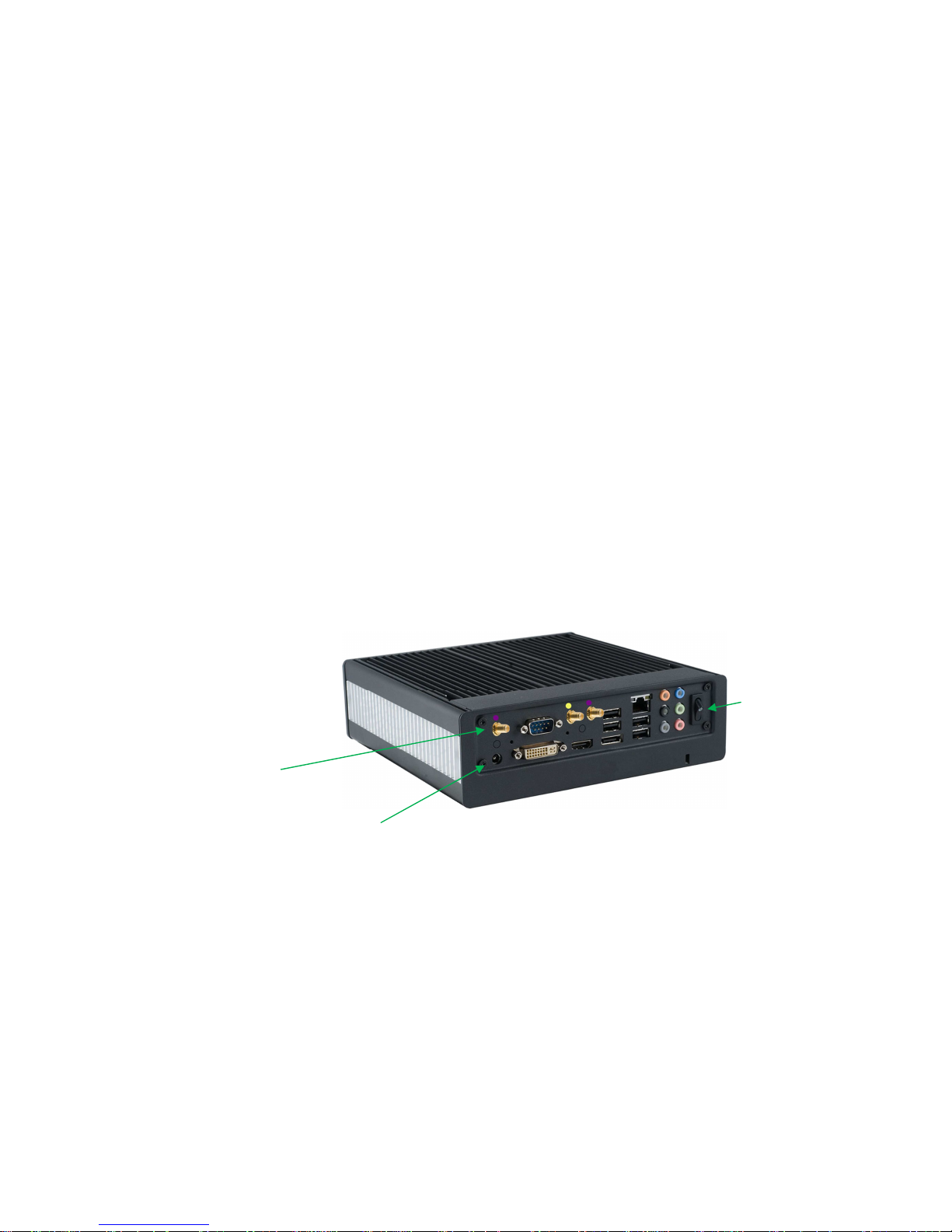
To configure the MiniHub, you will need to:
1.
Connect the AC power cable to the MiniHub and plug into a power source.
2.
Connect MiniHub Antennae
3.
Power on the MiniHub using the toggle button on the rear of the unit. Make sure the
Rugged-i camera and MiniHub are at least 25 feet away from each other.
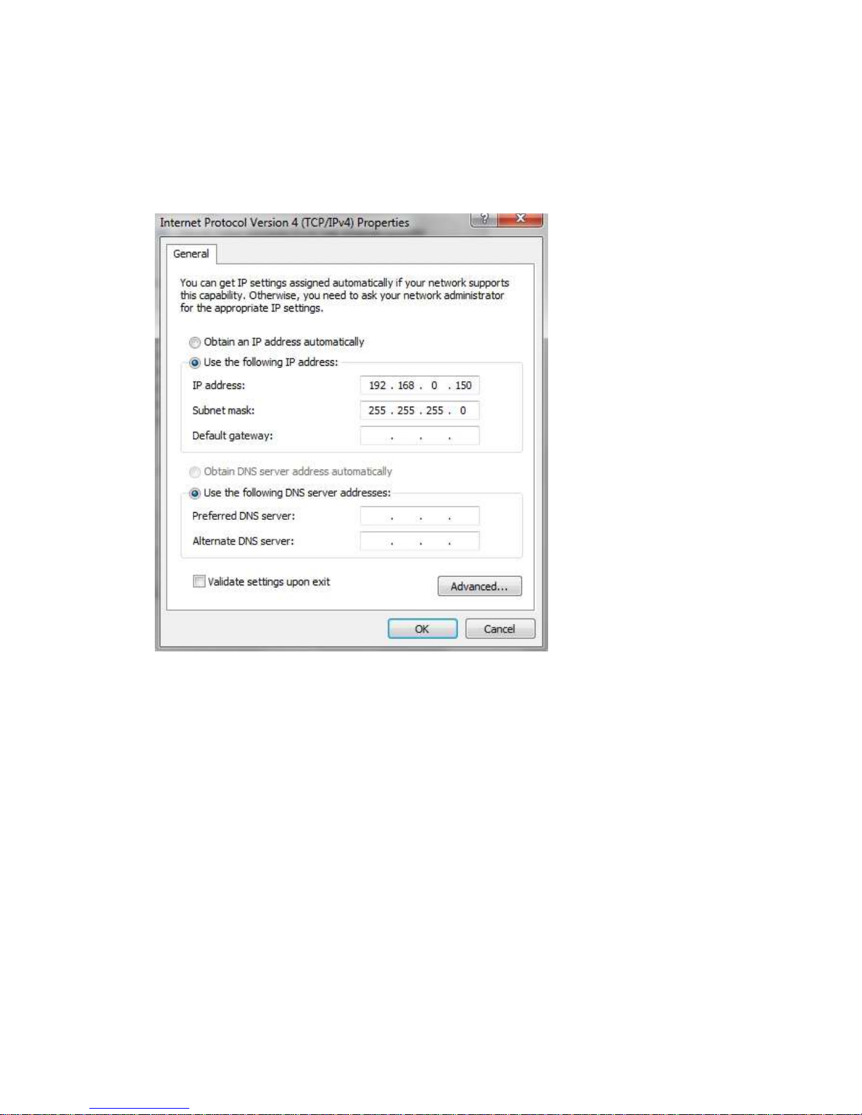
4.
Configure the network console so that it can directly address the MiniHub. The default
IP address of the MiniHub is 192.168.0.100. You may need to modify the IPv4 adapter
settings of the network console to match the default MiniHub IP address, since it is
required to be in the same domain to be addressable. To communicate to the MiniHub,
the first three numbers of the IP address of the network console need to match that of
the default MiniHub IP address. In this case, it is necessary to enter 192.168.0.XXX
where XXX is any number not previously issued within connected network.
Power Toggle
Button
Antenna Connector(s)
AC
Power
Helios Installation Guide
© 2012 MicroPower Technologies, Inc. 10
Below is an example screen of modifying the IPv4 properties in Windows to make this
change
.
Press OK.
5.
To communicate to the MiniHub through the network console, type the default IP
address of the MiniHub in a browser.
http://192.168.0.100
This is a temporary IP address which will eventually be modified through the system
setup application.
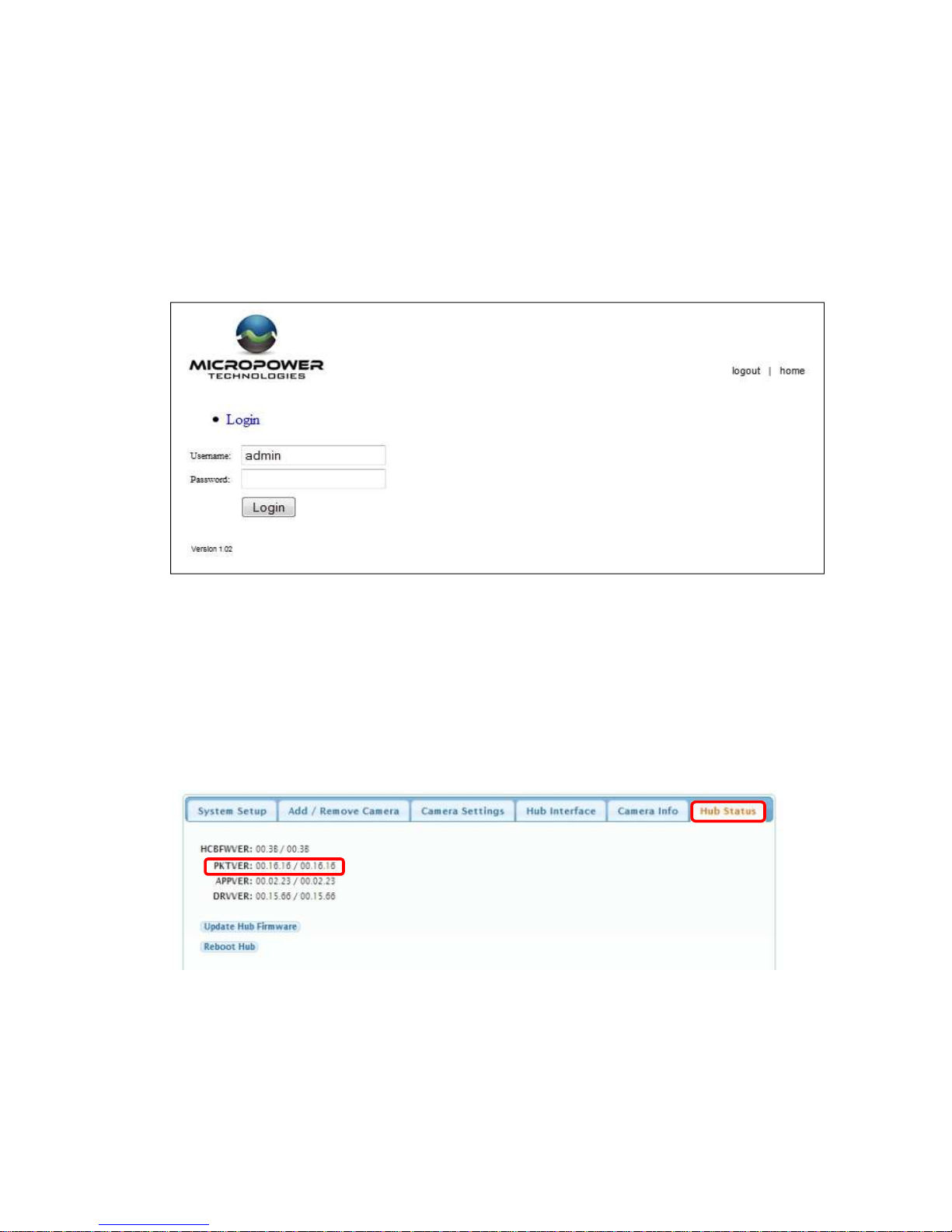
At this point, a login screen will appear. This is the MicroPower Technologies setup
application. This login screen will look like the following
:
Helios Installation Guide
© 2012 MicroPower Technologies, Inc. 11
Type in admin for the username. The password should be left blank.
At this point, the System Setup Web Interface will appear. Six tabs will be available; System
Setup, Add/Remove Camera, Camera Settings, Hub Interface, Camera Info and Hub Status. All
instructions and menu options to this Installation Guide pertain to Version 16.16 or greater.
You will note Version 16.16 by looking up the Version number in the Hub Status Tab.
The firmware version is located in the Web Interface on tab, Hub Status, under the heading
PKTVER. See below.
Helios Installation Guide
© 2012 MicroPower Technologies, Inc. 12
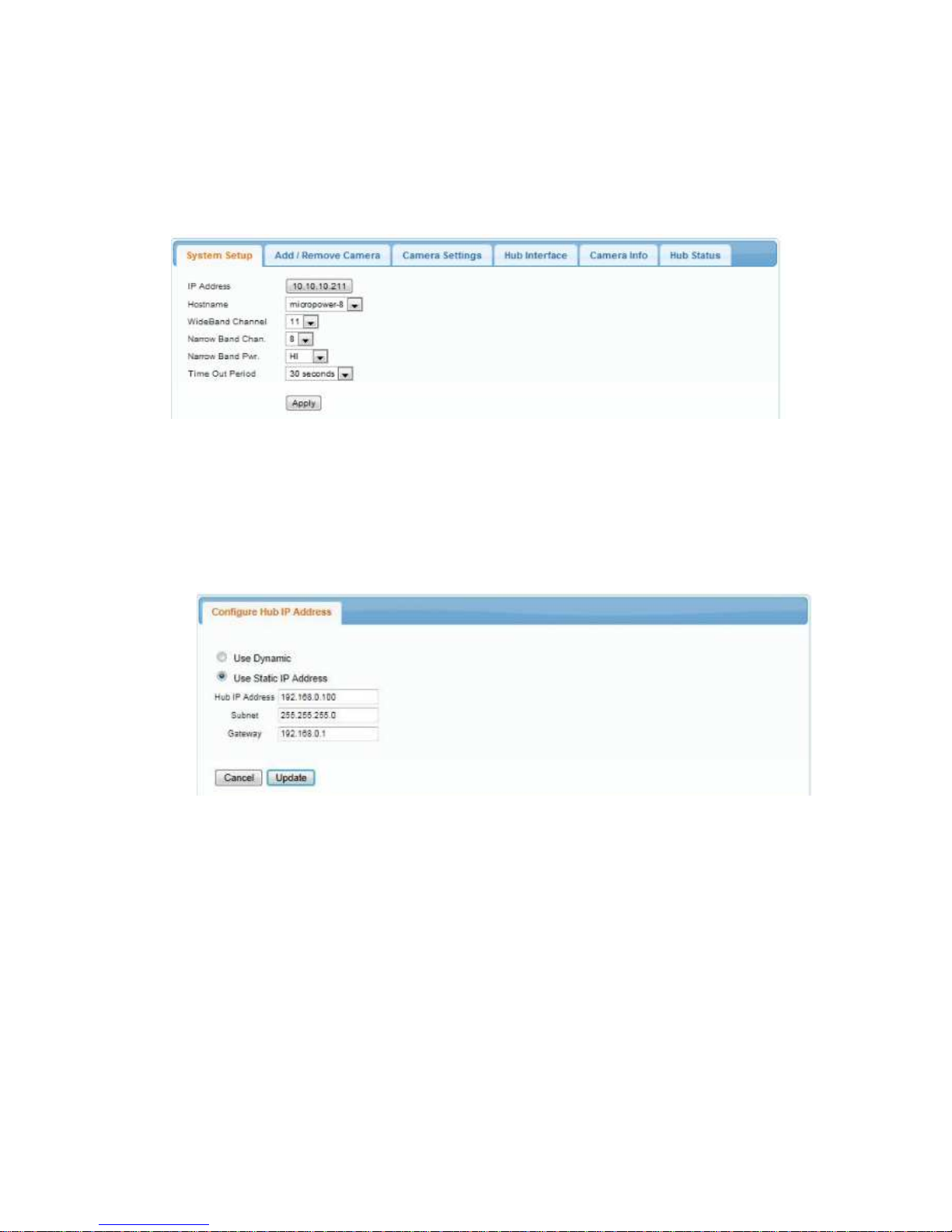
6.
Begin configuration of the MiniHub by selecting the System Setup tab.
This is the menu used to specify the final IP address, hostname, WiFi channel, Wi-Fi
bandwidth, narrow band channel number, narrow band channel power and time out period.
Typically, you will only need to change the IP address. To configure the IP address, single
click the IP address. The user will then be directed to a Configure Hub IP address menu.
See below.
This menu allows a user to modify a static IP address, gateway address, subnet address or
choose Dynamic otherwise known as DHCP (Dynamic Host Configuration Protocol).
Note: Caution should be used in using DHCP, since the IP address will be dynamic, making it
difficult to determine the appropriate IP address to access the setup menu in the MiniHub.
The only access to the MiniHub for setting modifications is by using the IP address as the
URL in the web browser. Hence, using DHCP would require assistance from the IT
administrator to perform discovery to determine the assigned IP address of the MiniHub at
the moment in which modifications are desired.
The new Hub IP address should correspond to the IP address within the subnet of your
network. For instance, should your devices be assigned an IP address of 192.168.100.1,
192.168.100.5 and 192.168.100.10, then a viable Hub IP address would be 192.168.100.150.

Helios Installation Guide
© 2012 MicroPower Technologies, Inc. 13
This allows other devices within your subnet network, including the NVR, to communicate
with each other. Input the desired IP address and select Update.
After updating the “Configure Hub IP Address menu”, you will be directed to the previous
menu, System Setup.
When Apply is selected at the System Setup tab, a dialog box will be displayed informing the
user that a system reboot is required, since the MiniHub will not be configured for the new
IP address until a reboot is complete. A manual reboot is performed by toggling the power
button in the back.
The other variables (WiFi Channel, Demod Level, Narrow Band Chan, Narrow Band Pwr) are
selectable, but should not be necessary to change.
7.
Address the hub through the network console and type in the new modified IP address.
http://xxx.xxx.xx.xx
The administration login screen will reappear. If there is a problem, then the IP address
may need to be readjusted on the IPv4 properties page so that the network adapter is
within the same domain as the new MiniHub IP Address.

Helios Installation Guide
© 2012 MicroPower Technologies, Inc. 14
C. Add/Remove Cameras
This is the menu used to add or remove cameras that are associated with the specific
hub that is being configured.
1.
Connect the antennas to the camera.
2.
Select Tab labeled Add/Remove Camera.
3.
Select option to “Add New”. A pop-up window for the MAC address of the camera is
displayed.
Add the MAC Address that is printed on the sticker of the Rugged-i camera. The sticker is
located inside the camera enclosure. You will need to open the safety latch on the camera
in order to access the inside of the Rugged-i camera.
Press OK when the MAC address is entered.
1.
Follow Step 3 again to add additional cameras (maximum of 6)

Helios Installation Guide
© 2012 MicroPower Technologies, Inc. 15
2.
Inside the camera enclosure, connect the battery charger cable to the battery
connector. The camera ships with a fully charged battery pack. However, when the
Rugged-i camera is shipped from the factory, the battery charger is disconnected from
the battery connection. While the camera enclosure is open, it is best to attach the
battery charger connectors together. You should hear a beep that indicates power
being supplied to the system, when you complete the connection.
The LED indicator light (on the left side while peering inside the camera) should glow red
when the battery is connected.
3.
Close the camera housing then lock the safety latch.

Helios Installation Guide
© 2012 MicroPower Technologies, Inc. 16
D. Camera Settings
The tab, Camera Settings, is used to customize each Rugged-i camera associated with
the paired MiniHub.
1. Select tab labeled Camera Settings.
Vvariables for the Camera Settings beyond the MAC address are:
Variable Description
Valid value for
Rugged-i cameras
MAC
Camera MAC Address
Six Hex values
WB Power
Power settings for the Wideband signal
Hi, Med, Lo
Demod
Data bandwidth of the individual
cameras
54, 48, 36, 24 Mbps
Fr. Rate
Frame rate desired.
5
Invert State
Specifies whether the video is an
inverted image or not.
Off
Encrypt State
Determines whether data uses
encryption between the Rugged-i and
MiniHub. This is a future feature.
Off
Stream Displays the stream ID of the camera
StreamX where X can
be 0 to 5
Use the Apply button at the end to apply new settings for that specific camera
The Align button is used for aligning antennas. See below for further information.

Helios Installation Guide
© 2012 MicroPower Technologies, Inc. 17
E. Align Mode
The very last button, Align, is a special button for determining the best alignment of
antennas between the MiniHub and Rugged-i cameras. The Web Interface allows the
user to see the Narrow band and Wideband wireless performance for each individual
camera.
This mode is especially useful while performing the installation, optimizing the camera,
Minihub, and antenna location and placement for the best performance for each
camera.
By selecting Align, the user will be directed into a new menu set that provide radio
measurements on the signal power, quality and noise of the narrowband (NB Signal)
and wideband (WB Signal) link.
The opening menu will look like below.
The meters are defined as you move left to right; top to bottom are:

Helios Installation Guide
© 2012 MicroPower Technologies, Inc. 18
• NB Signal (cam) = (915 MHz) signal strength received by the camera
• NB Signal (hub) = (915 MHz) signal strength received by the MiniHub
• NB Quality (cam) = (915 MHz) signal quality received by the camera
• NB Quality (hub) (915 MHz) signal quality received by the MiniHub
• WB Signal = (2.4 GHz) signal strength
• WB Noise = (2.4 GHz) noise level
• WB Quality = (2.4 GHz) signal quality
Note: The Narrow Band (NB) antennas have yellow bands on the bottom of the antenna
on both the camera and the MiniHub. The Wideband (WB) Band antennas have red
bands.
The steps for optimizing the alignment of the camera and MiniHub are:
1. Maximize the Narrow Band signal strength
2. Maximize the Narrow Band signal quality
3. Maximize the WiFi band signal strength
4. Maximize the WiFi band quality
IMPORTANT: YOU MUST SELECT
STOP AFTER COMPLETING THE ALIGNMENT
EXERCISE. IF STOP IS NOT PERFORMED, THE CAMERA AND MINIHUB WILL NOT
OPERATE PROPERLY.

Helios Installation Guide
© 2012 MicroPower Technologies, Inc. 19
Detailed instructions
#1. Adjust the Narrow Band signal strength to be as high as possible. Acceptable
ranges are -15 to -70. -15 is considered to be higher than -70. The values of the signal
strength received by the camera and MiniHub are expected to be approximately the
same value. If they are not within 5 units of each other, please call the factory for
assistance.
#2. Adjust the Narrow Band quality value to be as high as possible. Acceptable ranges
will vary based on the RF environment. However, in general, values above 35 should
yield an acceptable operation.
#3. Adjust the WiFi Band signal strength to be as high (closer to zero) as possible.
Acceptable ranges vary by environment. However, it will certainly work within the
range of -40 to -60. -40 is considered to be higher than -60. If the Demod value is
decreased to 36 Mbps, then acceptable values are -40 to -65. If the Demod value is
decreased to 24 Mbps, then acceptable values are -40 to -70.
#4. Adjust the WiFi Band quality value to be as high as possible. Acceptable ranges will
vary based on the RF environment. However, in general, values above 70 should yield
an acceptable operation.
IMPORTANT: YOU MUST SELECT STOP AFTER COMPLETING THE ALIGNMENT
EXERCISE. IF STOP IS NOT PERFORMED, THE CAMERA AND MINIHUB WILL NOT
OPERATE PROPERLY.
F. Hub Interface
When the MiniHub is shipped from the factory, the standard default mode hub interface
to the VMS system is set to the Native Mode. In the Native mode provides RTSP over
UDP (unicast) or HTTP over TCP as the primary interface to a VMS generic driver. For
some VMS systems, it is more appropriate to us the alternate mode, emulation mode.
Please refer to the specific VMS setup guide for the desired VMS guide to be used.
Below are a set of instruction on how to change the Hub Interface from the Native
Mode to the emulation mode.

Helios Installation Guide
© 2012 MicroPower Technologies, Inc. 20
Set Hub Interface to Emulation Mode
Note: Before adding cameras, the setup requires specifying a collection of IP addresses
for each camera. Before proceeding, obtain IP addresses from your network
administrator that are not assigned to other devices and which conform to the subnet of
the network over which the cameras and MiniHub will be communicating.
1) Point your browser to the IP address you assigned to the MiniHub and use the
updated IP address to log in to the web management interface of the MiniHub.
2) Select the Hub Interface tab in the web management interface. This will display the
Video Interface options.
3) Video Interface can select either the Native or Emulation mode. Select the
Emulation Mode via the pull-down menu.
4) Upon selection of the Emulation Mode, a table of camera MAC addresses and
associated IP Addresses will appear. These are camera MAC addresses that have
already been entered using the Add/Remove Camera menu. Complete the table by
entering static IP address(es) for each camera associated with this specific MiniHub,
as provided by your system administrator. There must be a unique IP address for
every camera that is to be added.
5) Once all the IP address(es) have been entered, select Apply.

Helios Installation Guide
© 2012 MicroPower Technologies, Inc. 21
6) Reboot the Hub by moving to the Hub Status Tab, and selecting the Reboot Hub
button.
G. Demod
For longer distances, it is recommended that lower demodulation levels be used. For
instance, 36 Mbps or 24 Mbps would be more appropriate for especiallly long distances
between the camera and the MiniHub. Each individual camera can be have their own
demodulation level.
Reboot Hub

Helios Installation Guide
© 2012 MicroPower Technologies, Inc. 22
G. Live View
The tab, Camera Info, is used as a diagnostic tab for MicroPower technical support and
for connecting Live Video to test the connection. In particular, Live View can help
determine whether a valid video stream is present, and whether non-operation is
occurring because of the VMS interface or the camera operation. Below is the opening
menu for Camera Info.
Selecting the camera of interest will diplay two additional tabs; Camera MAC Address
and Live View. The tab, Live View, will initiate a video connection between the MiniHub
and the Camera. Select connect.
This should display a live video screen of the camera. This display can be used to focus
the camera when the camera is mounted in its final position.

Helios Installation Guide
© 2012 MicroPower Technologies, Inc. 23
H. Battery Status
Additional Status codes are available in the tab where the camera MAC address is
displayed. The two primary status codes are:
• Battery Status
• Camera Status
Battery Status provides an indication whether the solar charging subsystem is charging
or discharging. Below is an example screen of when the solar subsystem is discharging.
Camera Status provides an indication whether the camera state is active, lost or asleep.
When the camera is asleep indicates the voltage on the battery is too low to maintain
operation.

Helios Installation Guide
© 2012 MicroPower Technologies, Inc. 24
III.
Mounting the MiniHub’s External Antenna
For professional installations, the MiniHub is required to use an external antennae.
MicroPower supplies an external antenna kit complete with a low loss RF cable, 2:1
splitter and a directional antennae. For optimal results, the height of the external
antenna from the MiniHub should be located at a minimum above any pedestrian
traffic that may occur in the line-of-sight between the MiniHub and Rugged-i
camera(s).
Directional Antenna for the MiniHub
The directional antenna attached to the MiniHub is required to communicate to
the various cameras. The directional antenna supplied by Micropower can transmit
and receive both the 900 MHz and 2.4 GHz frequencies. However, the 900 MHz
and 2.4 GHz channels from the MiniHub must be combined before being connected
to the directional antenna. In order to connect the channels together, a 2:1
splitter must used.
The 2:1 splitter must be connected as shown below. The output of the 2:1 splitter
is connected to the low loss RF cable.

Helios Installation Guide
© 2012 MicroPower Technologies, Inc. 25
Directional Antenna Specifications
The directional antenna should be mounted in a horizontal position. It is mounted
straight to the cameras. The cameras must be within 60 degrees of each other to
the MiniHub antenna. The directional antenna are mounted using a U-bolt to a
tower or attached to the side.

Helios Installation Guide
© 2012 MicroPower Technologies, Inc. 26

Helios Installation Guide
© 2012 MicroPower Technologies, Inc. 27
IV. Mounting the Camera and the Directional Antenna
Attach the mounting arm to the final location for the Rugged-i camera housing.
Below is the specification for the mounting arm.
The camera should be placed in an area which i receives an adequate amount of
direct sunlight throughout the day. Ideally the camera should be placed on the
south side. Other options are east and west locations, taking careful consideration
to avoid mounting the camera on the North side location. The locking mounting
bracket will allow the camera to remain in this position after it is installed.
The camera must use directional antennae and mounted using the included bracket.

Helios Installation Guide
© 2012 MicroPower Technologies, Inc. 28
IV.
Adjusting the Camera Image
Camera Lens Close-up View
1. While viewing the camera image through the Video Management System (VMS)
camera image window, adjustments can be made to the camera’s focal length,
iris or focus.
2. Open the camera housing using the safety latch at the rear of the unit. The
camera imager is located just behind the housing window.
2.1 To adjust focal length, turn the focal length locking knob counter-clockwise
to unlock. Rotate the focal length adjustment ring at the rear of the lens to
set. Turn the focal length locking knob clockwise to lock back into place.
2.2 To adjust iris, turn the iris locking knob counter-clockwise to unlock. Slide
the iris locking knob to the right or left to set. Turn the iris locking knob
clockwise to lock back into place.
2.3 To focus, turn the focus locking knob counter-clockwise to unlock. Rotate
the focus adjustment ring at the front of the lens to set. Turn focus locking
knob clockwise to lock in place.
2.4 After the imager adjustments have been completed, close the camera
housing and lock the latch into place.
After this step, setup is complete and the Rugged-i camera is ready for use.
Iris Locking Knob
Focus Locking
Knob
Focal Length
Locking Knob
Focal Length
Adjustment Ring
Focus
Adjustment
Ring

Helios Installation Guide
© 2012 MicroPower Technologies, Inc. 29
V. Configure the Video Management Software (VMS)
MicroPower Technologies has tested the MiniHub and Rugged-i cameras with various
VMS systems. MicroPower has developed interfaces to various VMS using either a
RTSP over UDP (unicast), HTTP over TCP/IP interface or the Axis emulation interface.
Please refer to our website for the latest list of tested VMS and NVRs that have been
tested for interoperability with the MicroPower Technologies systems. Please refer to
the document VMS Setup Guide for specific instructions for each supported VMS.

Helios Installation Guide
© 2012 MicroPower Technologies, Inc. 30
INFORMATION TO USER
This device complies with Part 15 of the FCC Rules. Operation is subject to the following
two conditions: (1) This device may not cause harmful interference, and (2) This device
must accept any interference received, including interference that may cause undesired
operation.
This equipment has been tested and found to comply with the limits for Class B Digital
Device, pursuant to Part 15 of the FCC Rules. These limits are designed to provide
reasonable protection against harmful interference in a residential installation. This
equipment generates and can radiate radio frequency energy and, if not installed and
used in accordance with the instructions, may cause harmful interference to radio
communications. However, there is no guarantee that interference will not occur in a
particular installation. If this equipment does cause harmful interference to radio or
television reception, which can be determined by turning the equipment off and on, the
user is encouraged to try to correct the interference by one or more of the following
measures.
• Reorient or relocate the receiving antenna
• Increase the separation between the equipment and receiver
• Connect the equipment into an outlet on a circuit different from that to which
the receiver is connected
• Consult the dealer or an experienced radio/TV technician for help
Any changes or modifications not expressly approved by the party responsible
for compliance could void the user’s authority to operate the equipment.

Helios Installation Guide
© 2012 MicroPower Technologies, Inc. 31
MicroPower Technologies
END-USER LICENSE AGREEMENT
for IP SECURITY SYSTEM SOFTWARE AND/OR FIRMWARE
IMPORTANT - READ CAREFULLY
This End User Software License Agreement (this "EULA") is a legal agreement between you, the individual or entity that has
agreed to pay for the rights granted herein ("Licensee"), and MicroPower Technologies, Inc., a Delaware corporation (“MPT”).
This EULA governs Licensee's possession and use of the Software and the Documentation (each as defined below).
BY CHECKING AND/OR CLICKING “I ACCEPT” OR A SIMILAR BOX OR BUTTON ASSOCIATED WITH THIS EULA AT THE BEGINNING OF
THE SOFTWARE DOWNLOAD, INSTALLATION, OR ACTIVATION PROCESS, BY INSTALLING ANY OF THE SOFTWARE, BY ACTIVATING
ANY OF THE SOFTWARE WITH ANY ASSOCIATED LICENSE KEY, OR BY USING ANY OF THE SOFTWARE, LICENSEE AGREES TO ALL OF
THE TERMS AND CONDITIONS IN THIS EULA. IF LICENSEE DOES NOT AGREE TO ALL OF THE TERMS AND CONDITIONS IN THIS EULA,
LICENSEE MUST NOT INSTALL, ACTIVATE, OR USE ANY OF THE SOFTWARE, AND LICENSEE MUST NOT CHECK AND/OR CLICK “I
ACCEPT” OR ANY SIMILAR BOX OR BUTTON ASSOCIATED WITH THIS EULA DURING THE SOFTWARE DOWNLOAD, INSTALLATION,
OR ACTIVATION PROCESS. IF LICENSEE DOES NOT AGREE TO ALL OF THE TERMS AND CONDITIONS IN THIS EULA, LICENSEE MAY
RETURN THE UNUSED SOFTWARE FOR A FULL REFUND, PROVIDED THAT LICENSEE'S RIGHT TO RETURN THE UNUSED SOFTWARE
FOR A FULL REFUND EXPIRES THIRTY (30) DAYS AFTER THE PURCHASE OF THE SOFTWARE FROM MPT OR A MPT-AUTHORIZED
RESELLER OR DISTRIBUTOR, AND APPLIES ONLY IF LICENSEE IS THE ORIGINAL END USER PURCHASER.
1. DEFINITIONS. As used herein, the following terms shall have the following meanings:
1.1. “Documentation” means any and all end user documentation provided by MPT in connection with the Software, and all
Updates thereto.
1.2. “Factory Installed Software” means Software that is installed by MPT on a MPT hardware product prior to delivery of that
MPT hardware product to Licensee, and all Updates thereto. Factory Installed Software may include, without limitation, TrustLinx
firmware, and certain third party file server programs.
1.3. “GPL Software” refers to certain open source software that MPT may provide to Licensee in connection with a MPT hardware
product, including but not limited to the Linux software provided by MPT in connection with the MPT2500, MPT2600 and MPT2700
products. GPL Software is provided by MPT to Licensee solely under the terms of the GNU General Public License, Version 2, June
1991 (the “GNU GPL”), a copy of which accompanies this Agreement. Consistent with the requirements of the GNU GPL, MPT will
provide a complete machine-readable copy of the source code for GPL Software for a charge of no more than MPT's cost of
physically performing such distribution, provided that such copy is requested within three (3) years following Licensee's receipt of
the corresponding GPL Software from MPT.
1.4. “Remote Software” means Software that is meant to be installed on Licensee's own hardware and that is not installed by MPT
or a MPT reseller on a MPT hardware product prior to delivery of that MPT hardware product to Licensee, and all Updates thereto.
Remote Software may include, without limitation, MPT's Web Interface or GUI program.
1.5. “Software” means all software and firmware that accompanies this EULA, all copies thereof, all media associated therewith, and
all Updates thereto; provided that the term “Software” does mean any software or other materials for which a separate end user
license agreement is provided (including but not limited to the GPL Software).
1.6. “Updates” means any and all updates, upgrades, new releases, modifications, and/or supplements that may be provided by
MPT from time to time, whether through an online download process or otherwise.
1.7. “Use” means to install, store, load, execute, and display one copy of the Software on one device at a time for Licensee's internal
business purposes.
2. LICENSE GRANTS.
2.1. Software. Subject to all terms and conditions in this EULA, MPT hereby grants to Licensee a limited, revocable, non exclusive,
non sublicenseable license to:
(a) Use Factory Installed Software, only in object code form, and only on the MPT hardware products that are purchased by Licensee
and that contain such software when first delivered to Licensee, provided that Licensee may not use Factory Installed Software in
connection with any IP video cameras or IP video camera subsystems that were not purchased from MPT, and provided further that
(i) MPT2500 firmware may only be used with the MPT2500 specified in the corresponding invoice;
(ii) MPT2600 firmware may only be used with the MPT2600 specified in the corresponding invoice
(iii) MPT2700 firmware may only be used with the MPT2600 specified in the corresponding invoice.
(b) Use Remote Software, only in object code form, and only on the number of Licensee computers for which Licensee has
purchased a license (as specified in the corresponding invoice).
2.2. Documentation. Subject to all terms and conditions in this EULA, MPT hereby grants to Licensee a limited, revocable,
non-exclusive, non-sublicenseable license to copy and use the Documentation to the limited extent reasonably necessary to support
Licensee's permissible Use of the Software.
3. OWNERSHIP. Licensee acknowledges and agrees that MPT, its suppliers, and/or its licensors, as applicable, own and shall retain all
rights, title, and interest in and to the Software and the Documentation, including but not limited to all patents, trademarks, trade
names, inventions, copyrights, know how, trade secrets, and other intellectual and industrial property rights (and any corresponding

Helios Installation Guide
© 2012 MicroPower Technologies, Inc. 32
applications or registrations) related to the Software or the Documentation. MPT's suppliers and licensors are intended beneficiaries
under this EULA and independently may protect their rights in the Software and the Documentation in the event of any infringement
or breach of this EULA.
4. RESERVATION OF RIGHTS. Licensee acknowledges and agrees that the Software and the Documentation have been licensed to
Licensee pursuant to the terms and conditions of this EULA, and that the Software and the Documentation have not been sold to
Licensee. MPT and its suppliers and licensors reserve all rights not expressly granted herein. Licensee shall not use or copy the
Software or the Documentation except as is expressly authorized in this EULA. Licensee acknowledges and agrees that the Software
and the Documentation are protected by United States copyright laws and international treaty provisions. Except as otherwise
expressly provided herein, Licensee must treat the Software and the Documentation like any other copyrighted material. Licensee
shall not knowingly take any action that would cause the Software or the Documentation to be placed in the public domain.
5. RESTRICTIONS.
5.1. Usage Restrictions. Licensee shall not permit any person other than Licensee's employees and authorized agents to possess
or use the Software or the Documentation, and Licensee shall cause all such employees and authorized agents to abide by all terms
and conditions imposed upon Licensee herein. Licensee may not exceed the number of licenses, agents, tiers, nodes, seats, or other
Use restrictions or authorizations agreed to and paid for by Licensee. Licensee shall not use the Software to operate nuclear
facilities, life support, or any other mission critical application where human life or property may be at stake, and Licensee
understands that the Software is not designed for such purposes and that its failure in such cases could lead to death, personal
injury, or severe property or environmental damage for which MPT and its suppliers and licensors are not responsible. Some
Software may require license keys or contain other technical protection measures. Licensee acknowledges that MPT may monitor
Licensee's compliance with Use restrictions and authorizations, remotely or otherwise. If MPT makes a license management
program available which records and reports Software usage information, Licensee agrees to appropriately install, configure, and
execute such license management program beginning no later than one hundred and eighty (180) days from the date it is made
available to Licensee and continuing for the period that the Software is used.
5.2. No Transfer. Licensee may not, and agrees that it will not, transfer, assign, rent, lease, lend, resell, or in any way distribute or
transfer the Software or the Documentation (or any rights in this EULA, the Software, or the Documentation) to any third parties,
including by operation of law, without MPT's prior written approval, payment to MPT of any applicable fees, and compliance with
applicable third party terms. Upon any approved transfer of this EULA, Licensee's rights hereunder will terminate and Licensee will
immediately deliver the Software, the Documentation, and all copies thereof to the transferee. The transferee must agree in writing
to the terms of this EULA and, upon such agreement, the transferee will be considered the “Licensee” for purposes of this EULA.
Licensee may transfer Factory Installed Software only upon transfer of the associated MPT hardware product.
5.3. No Reverse Engineering; No Modification. To the maximum extent permitted by applicable law, Licensee shall not reverse
engineer, disassemble, decrypt, or decompile the Software, or otherwise attempt to discover, reconstruct, or identify the source
code for the Software or any user interface techniques, algorithms, logic, protocols, or specifications included, incorporated, or
implemented therein. Furthermore, to the maximum extent permitted by applicable law, Licensee shall not modify, port, or
translate the Software or the Documentation. Where Licensee has other rights with respect to the Software or the Documentation
mandated under statute, Licensee will provide MPT with reasonably detailed information regarding any intended modifications,
porting, translations, reverse engineering, disassembly, decryption, or decompilation, and the purposes therefore.
5.4. Proprietary Notices and Legends. If Licensee makes any copies of the Software or the Documentation in accordance with this
EULA, Licensee must reproduce in all such copies all proprietary notices and legends contained in the originals.
5.5. Updates. Upon Licensee's installation of any Update to Software, Licensee shall have no further rights, and MPT shall have no
further obligations, with respect to those portions of the Software that such Update was intended to replace. If additional or
different license terms or conditions accompany an Update, Licensee acknowledges and agrees that Licensee's Use of that Update
will be subject to those additional or different terms and conditions.
5.6. Export Restrictions; Compliance with Laws. Licensee agrees that Licensee will not, directly or indirectly, export or transmit the
Software or the Documentation to any country, entity, or person to which such export or transmission is restricted by any applicable
government regulation or statute without the prior written consent, if required, of the governmental entity as may have jurisdiction
over such export or transmission. Licensee agrees to comply with and conform to all applicable laws, regulations, and ordinances
relating to Licensee's use of the Software and/or the Documentation.
6. RESPONSIBILITIES OF LICENSEE.
6.1. Payment. In consideration for the licenses and rights granted to Licensee herein, Licensee agrees to pay all amount(s) for such
licenses and rights as set forth in the corresponding invoice, in accordance with the payment terms agreed upon by Licensee.
6.2. Indemnification. Licensee hereby agrees to indemnify, protect, defend, and hold MPT and its licensors harmless from and
against any and all claims, losses, or damages (including but not limited to reasonable attorneys' and experts' fees) attributable to
(a) Licensee's use or misuse of the Software or the Documentation, or
(b) any failure by Licensee to comply with any term, condition, or restriction in this EULA.
7. COMPLIANCE AUDIT. MPT shall have the right, upon reasonable notice, to conduct and/or have an independent accounting firm
conduct, during normal business hours on Licensee's premises under Licensee's reasonable supervision, an audit to verify Licensee's
compliance with the terms of this EULA. If an audit reveals underpayments, then Licensee will immediately pay MPT such
underpayments together with the costs reasonably incurred by MPT in connection with the audit and seeking compliance with this
section.

Helios Installation Guide
© 2012 MicroPower Technologies, Inc. 33
8. USE OF LICENSEE INFORMATION. With respect to any information Licensee provides to MPT in connection with the Software or
the Documentation, MPT may use such information for any purpose without restriction, including, without limitation, for product
support and development purposes, provided that MPT will not use such information in a form that identifies Licensee.
9. TERM AND TERMINATION.
9.1. General. Except as provided below with respect to evaluation and limited term licenses, this EULA and the license(s) granted
herein will remain effective until terminated. Licensee may terminate this EULA and the licenses granted herein by ceasing all use of
the Software and the Documentation, and returning all copies of the Software and the Documentation to MPT. This EULA (including
but not limited to the licenses granted to Licensee herein) will automatically terminate if Licensee fails to comply with any term or
condition of this EULA.
9.2. Evaluation and Term Licenses. If the Software and the Documentation have been licensed to Licensee for evaluation purposes,
this EULA will be effective only until the end of the designated evaluation period. If the Software and the Documentation have been
licensed to Licensee for a limited term as specified in the applicable sales acknowledgement, invoice, or otherwise, then this EULA
will be effective only until the end of such term. Software that is subject to any evaluation or limited term license may contain code
that can disable most or all of the features of such software upon expiration of such evaluation or limited term license, and unless
Licensee has paid the applicable license fee for any additional licenses, Licensee shall have no rights to use such Software or the
corresponding Documentation upon expiration of any such license.
9.3. Obligations Upon Termination or Expiration. Licensee agrees, upon any termination or expiration of this EULA, to cease use of,
and to destroy or return to MPT, all copies of the Software and the Documentation. At MPT's request, Licensee will certify in writing
to MPT that Licensee has complied with these requirements. Notwithstanding anything in this EULA to the contrary, Sections 1, 3, 4,
5.3, 5.6, 6, 7, 8, 9, 10.2, 10.3, 11, 12, and 13 of this EULA shall survive any expiration or termination of this EULA and continue in
perpetuity.
10. LIMITED WARRANTY; DISCLAIMER; LIMITATION OF LIABILITY.
10.1. Limited Warranty. MPT warrants only to the original Licensee that, for a period of two (2) years following MPT's initial
shipment of Software (and not Updates thereto) to such Licensee, such Software, as delivered to such Licensee, will substantially
conform to the corresponding Documentation. Licensee's sole and exclusive remedy, and MPT's entire liability, under this warranty
is for MPT to use commercially reasonable efforts to cause the defective or malfunctioning Software to substantially conform to the
corresponding Documentation. Notwithstanding the foregoing, MPT will have no liability for any defective or malfunctioning
Software under this Section 10.1 if (a) Licensee fails to notify MPT of the defect or malfunction during the Warranty Period, or (b)
the defect or malfunction is caused by (i) use of such Software in combination with any hardware or other software that has not
been approved in writing by MPT, (ii) the negligence or fault of Licensee or a third party, (iii) Licensee's failure to follow the
instructions set forth in the corresponding Documentation, or (iv) modifications to that Software made by any person other than
MPT or an authorized representative of MPT.
10.2. Disclaimer. TO THE MAXIMUM EXTENT PERMITTED BY APPLICABLE LAW, EXCEPT AS EXPRESSLY SET FORTH IN SECTION 10.1
ABOVE, THE SOFTWARE AND THE DOCUMENTATION ARE PROVIDED “AS IS”, AND MPT AND ITS SUPPLIERS AND LICENSORS DO NOT
MAKE AND SPECIFICALLY DISCLAIM ALL EXPRESS AND IMPLIED WARRANTIES OF EVERY KIND RELATING TO THE SOFTWARE, THE
DOCUMENTATION, AND/OR USE OF THE SOFTWARE OR THE DOCUMENTATION (INCLUDING, WITHOUT LIMITATION, ACTUAL AND
IMPLIED WARRANTIES OF MERCHANTABILITY, FITNESS FOR A PARTICULAR PURPOSE, AND NON INFRINGEMENT), AS WELL AS ANY
WARRANTIES THAT THE SOFTWARE OR THE DOCUMENTATION (OR ANY ELEMENTS OF EITHER) WILL ACHIEVE A PARTICULAR
RESULT, OR WILL BE UNINTERRUPTED OR ERROR FREE.
10.3. Limitation of Liability. TO THE MAXIMUM EXTENT PERMITTED BY APPLICABLE LAW, IN NO EVENT SHALL MPT OR ITS SUPPLIERS
OR LICENSORS BE LIABLE UNDER ANY THEORY OF LIABILITY FOR ANY CONSEQUENTIAL, INDIRECT, INCIDENTAL, SPECIAL, PUNITIVE,
OR EXEMPLARY DAMAGES OF ANY KIND (INCLUDING, WITHOUT LIMITATION, DAMAGES ARISING FROM LOSS OF PROFITS, REVENUE,
DATA, OR USE, OR FROM INTERRUPTED COMMUNICATIONS OR DAMAGED DATA, OR FROM ANY DEFECT OR ERROR, OR IN
CONNECTION WITH LICENSEE'S ACQUISITION OF SUBSTITUTE GOODS OR SERVICES OR MALFUNCTION OF THE SOFTWARE, OR ANY
SUCH DAMAGES ARISING FROM BREACH OF CONTRACT OR WARRANTY OR FROM NEGLIGENCE OR STRICT LIABILITY) IN
CONNECTION WITH THIS EULA, THE SOFTWARE, THE DOCUMENTATION, AND/OR ANY USE OF THE SOFTWARE OR THE
DOCUMENTATION, EVEN IF MPT OR ANY OF ITS SUPPLIERS OR LICENSORS OR ANY OTHER PERSON HAS BEEN ADVISED OR SHOULD
KNOW OF THE POSSIBILITY OF SUCH DAMAGES, AND NOTWITHSTANDING THE FAILURE OF ANY REMEDY TO ACHIEVE ITS INTENDED
PURPOSE. WITHOUT LIMITING THE FOREGOING, MPT'S MAXIMUM AGGREGATE LIABILITY IN CONNECTION WITH THIS EULA, THE
SOFTWARE, THE DOCUMENTATION, AND/OR USE OF THE SOFTWARE OR THE DOCUMENTATION SHALL NOT EXCEED THE TOTAL
AMOUNT OF ANY LICENSE FEES AND/OR MAINTENANCE FEES PAID BY LICENSEE IN CONNECTION WITH THE SOFTWARE.
11. U.S. GOVERNMENT RESTRICTED RIGHTS.
11.1. Commercial Software. The Software and the Documentation are deemed to be “commercial computer software” and
“commercial computer software documentation,” respectively, for purposes of Federal Acquisition Regulations (“FAR”) 12.212 and
the Defense FAR Supplement (“DFARS”) 227.7202-1, 227.7202-3, and 227.7202-4, and the restrictions set forth in such regulations,
and this EULA shall be deemed to be the license described in such regulations. Any use, modification, reproduction, release,
performance, display, or disclosure of the Software or the Documentation by any agency, department, or entity of the United States
Government (the “Government”) shall be governed solely by the terms of this EULA and is prohibited except to the extent expressly
permitted by the terms of this EULA. The Software and the Documentation are also deemed to be “restricted computer software”
for purposes of FAR 52.227-14(g)(3) (Alternate III (June 1987)) and FAR 52.227-19, which clauses are incorporated herein by
reference subject to the express restrictions and prohibitions set forth above.
11.2. Certain Technical Data. Any technical data provided by MPT in connection with the Software or the Documentation that is not
covered by the above provisions is deemed to be “technical information related to commercial computer software or commercial

Helios Installation Guide
© 2012 MicroPower Technologies, Inc. 34
computer software documentation” for purposes of FAR 12.212 and the restrictions set forth therein, and is deemed to be
“technical data or information related or pertaining to commercial items or processes” developed at private expense for purposes of
DFARS 227.7102-1
and 227.7102 2 and the restrictions set forth therein, and this EULA shall be deemed to be the license described in such regulations.
Any use, modification, reproduction, release, performance, display, or disclosure of such technical data by the Government shall be
governed solely by the terms of this EULA and is prohibited except to the extent expressly permitted by the terms of this EULA. Such
technical data is also deemed to be “limited rights data” as defined in FAR 52.227-14(a) (Alternate I (June 1987)) and for purposes of
FAR 52.227-14(g)(2) (Alternate II (June 1987)), which clauses are incorporated herein by reference subject to the express restrictions
and prohibitions set forth above. Such technical data shall also be deemed to be “technical data” for purposes of DFARS 252.2277015, which clause is incorporated herein by reference subject to the express restrictions and prohibitions set forth above.
11.3. Third Party Acceptance of Restrictions. Licensee shall not provide the Software, the Documentation, or the technical data
described in Section 11.2 above to any party, including but not limited to the Government, unless such third party accepts the same
restrictions as are set forth in this Section 11. Licensee is responsible for ensuring that the proper notice is given to all such third
parties and that the Software, the Documentation, and such technical data is properly marked with the required legends. Nothing in
this Section 11.3 shall be deemed to modify the restrictions on transfer or disclosure set forth elsewhere in this EULA.
12. GOVERNING LAW; ENFORCEMENT.
12.1. Governing Law. This EULA and the rights and obligations of the parties hereunder shall be governed by the laws of the State of
California, without reference to conflicts of laws principles; provided, however, that if the Software and the Documentation is
licensed outside the United States, then certain local laws may apply. The parties agree to the non exclusive jurisdiction of the state
and federal courts in San Diego County, California in connection with the litigation of any dispute pertaining to this EULA and waive
any objection to such jurisdiction based on venue or personal jurisdiction. IN ADDITION, THIS EULA WILL NOT BE GOVERNED OR
INTERPRETED IN ANY WAY BY REFERRING TO ANY LAW BASED ON THE UNIFORM COMPUTER INFORMATION TRANSACTIONS ACT
(UCITA), EVEN IF THAT LAW HAS BEEN ADOPTED IN CALIFORNIA, AND THE UNITED NATIONS CONVENTION ON CONTRACTS FOR THE
INTERNATIONAL SALE OF GOODS IS HEREBY EXCLUDED.
12.2. Equitable Relief. Licensee acknowledges that any actual or threatened breach of the provisions of this EULA will constitute
immediate, irreparable harm to MPT for which monetary damages would be an inadequate remedy; that injunctive relief is an
appropriate remedy for any such breach or threatened breach; and that, in such event, MPT will be entitled to immediate injunctive
relief without the requirement of posting bond.
13. MISCELLANEOUS. Except as otherwise expressly agreed in a written, signed agreement between MPT and Licensee, this EULA
sets forth the entire agreement between MPT and Licensee with respect to the Software, the Documentation, and/or Licensee's use
of the Software and the Documentation, and it is expressly agreed that the terms of this EULA will supersede the terms in any of
Licensee's purchase orders or other ordering documents. There are no implied licenses with respect to the Software or the
Documentation. No provision of this EULA may be waived, modified, or superseded except by a written instrument signed by each of
MPT and Licensee. No failure or delay in exercising any right or remedy shall operate as a waiver of any such (or any other) right or
remedy. The language of this EULA shall be construed as a whole, according to its fair meaning and intent, and not strictly for or
against either party, regardless of who drafted or was principally responsible for drafting this EULA or any specific term or condition
hereof. This EULA shall bind and inure to the benefit of the parties and their successors and permitted assigns. Both parties are
acting as independent contractors with respect to the activities hereunder. In the event of any legal proceeding between the parties
arising out of or related to this EULA, the prevailing party shall be entitled to recover, in addition to any other relief awarded or
granted, its costs and expenses (including but not limited to reasonable attorneys' and expert witness' fees) incurred in any such
proceeding. If any provision in this EULA is invalid or unenforceable, such provision shall be construed, limited, or altered, as
reasonably necessary, to eliminate the invalidity or unenforceability and all other provisions of this EULA shall remain in effect.
------------------------------------------------------------------------------------------------------------------------------------------------------------------------------Should Licensee have any questions concerning this EULA, or if Licensee desires to contact MicroPower Technologies for any reason,
please contact the company at:
4225 Executive Square, Suite 430, La Jolla, CA 92037, or send an email to MicroPower Technologies at support@micropowerapp.com.

Helios Installation Guide
© 2012 MicroPower Technologies, Inc. 35
GNU GENERAL PUBLIC LICENSE
TERMS AND CONDITIONS FOR COPYING, DISTRIBUTION AND MODIFICATION
0. This License applies to any program or other work which contains a notice placed by the copyright holder saying it may be
distributed under the terms of this General Public License. The "Program", below, refers to any such program or work, and a "work
based on the Program" means either the Program or any derivative work under copyright law: that is to say, a work containing the
Program or a portion of it, either verbatim or with modifications and/or translated into another language. (Hereinafter, translation is
included without limitation in the term "modification".) Each licensee is addressed as "you".
Activities other than copying, distribution and modification are not covered by this License; they are outside its scope. The act of
running the Program is not restricted, and the output from the Program is covered only if its contents constitute a work based on
the Program (independent of having been made by running the Program). Whether that is true depends on what the Program does.
1. You may copy and distribute verbatim copies of the Program's source code as you receive it, in any medium, provided that you
conspicuously and appropriately publish on each copy an appropriate copyright notice and disclaimer of warranty; keep intact all the
notices that refer to this License and to the absence of any warranty; and give any other recipients of the Program a copy of this
License along with the Program.
You may charge a fee for the physical act of transferring a copy, and you may at your option offer warranty protection in exchange
for a fee.
2. You may modify your copy or copies of the Program or any portion of it, thus forming a work based on the Program, and copy and
distribute such modifications or work under the terms of Section 1 above, provided that you also meet all of these conditions:
a. You must cause the modified files to carry prominent notices stating that you changed the files and the date of any
change.
b. You must cause any work that you distribute or publish, that in whole or in part contains or is derived from the Program
or any part thereof, to be licensed as a whole at no charge to all third parties under the terms of this License.
c. If the modified program normally reads commands interactively when run, you must cause it, when started running for
such interactive use in the most ordinary way, to print or display an announcement including an appropriate copyright
notice and a notice that there is no warranty (or else, saying that you provide a warranty) and that users may redistribute
the program under these conditions, and telling the user how to view a copy of this License. (Exception: if the Program
itself is interactive but does not normally print such an announcement, your work based on the Program is not required
to print an announcement.)
These requirements apply to the modified work as a whole. If identifiable sections of that work are not derived from the Program,
and can be reasonably considered independent and separate works in themselves, then this License, and its terms, do not apply to
those sections when you distribute them as separate works. But when you distribute the same sections as part of a whole which is a
work based on the Program, the distribution of the whole must be on the terms of this License, whose permissions for other
licensees extend to the entire whole, and thus to each and every part regardless of who wrote it.
Thus, it is not the intent of this section to claim rights or contest your rights to work written entirely by you; rather, the intent is to
exercise the right to control the distribution of derivative or collective works based on the Program.
In addition, mere aggregation of another work not based on the Program with the Program (or with a work based on the Program)
on a volume of a storage or distribution medium does not bring the other work under the scope of this License.
3. You may copy and distribute the Program (or a work based on it, under Section 2) in object code or executable form under the
terms of Sections 1 and 2 above provided that you also do one of the following:
a. Accompany it with the complete corresponding machine-readable source code, which must be distributed under the
terms of Sections 1 and 2 above on a medium customarily used for software interchange; or,
b. Accompany it with a written offer, valid for at least three years, to give any third party, for a charge no more than your
cost of physically performing source distribution, a complete machine-readable copy of the corresponding source code,
to be distributed under the terms of Sections 1 and 2 above on a medium customarily used for software interchange; or,

Helios Installation Guide
© 2012 MicroPower Technologies, Inc. 36
c. Accompany it with the information you received as to the offer to distribute corresponding source code. (This alternative
is allowed only for noncommercial distribution and only if you received the program in object code or executable form
with such an offer, in accord with Subsection b above.)
The source code for a work means the preferred form of the work for making modifications to it. For an executable work, complete
source code means all the source code for all modules it contains, plus any associated interface definition files, plus the scripts used
to control compilation and installation of the executable. However, as a special exception, the source code distributed need not
include anything that is normally distributed (in either source or binary form) with the major components (compiler, kernel, and so
on) of the operating system on which the executable runs, unless that component itself accompanies the executable.
If distribution of executable or object code is made by offering access to copy from a designated place, then offering equivalent
access to copy the source code from the same place counts as distribution of the source code, even though third parties are not
compelled to copy the source along with the object code.
4. You may not copy, modify, sublicense, or distribute the Program except as expressly provided under this License. Any attempt
otherwise to copy, modify, sublicense or distribute the Program is void, and will automatically terminate your rights under this
License. However, parties who have received copies, or rights, from you under this License will not have their licenses terminated so
long as such parties remain in full compliance.
5. You are not required to accept this License, since you have not signed it. However, nothing else grants you permission to modify
or distribute the Program or its derivative works. These actions are prohibited by law if you do not accept this License. Therefore, by
modifying or distributing the Program (or any work based on the Program), you indicate your acceptance of this License to do so,
and all its terms and conditions for copying, distributing or modifying the Program or works based on it.
6. Each time you redistribute the Program (or any work based on the Program), the recipient automatically receives a license from
the original licensor to copy, distribute or modify the Program subject to these terms and conditions. You may not impose any
further restrictions on the recipients' exercise of the rights granted herein. You are not responsible for enforcing compliance by third
parties to this License.
7. If, as a consequence of a court judgment or allegation of patent infringement or for any other reason (not limited to patent
issues), conditions are imposed on you (whether by court order, agreement or otherwise) that contradict the conditions of this
License, they do not excuse you from the conditions of this License. If you cannot distribute so as to satisfy simultaneously your
obligations under this License and any other pertinent obligations, then as a consequence you may not distribute the Program at all.
For example, if a patent license would not permit royalty-free redistribution of the Program by all those who receive copies directly
or indirectly through you, then the only way you could satisfy both it and this License would be to refrain entirely from distribution
of the Program.
If any portion of this section is held invalid or unenforceable under any particular circumstance, the balance of the section is
intended to apply and the section as a whole is intended to apply in other circumstances.
It is not the purpose of this section to induce you to infringe any patents or other property right claims or to contest validity of any
such claims; this section has the sole purpose of protecting the integrity of the free software distribution system, which is
implemented by public license practices. Many people have made generous contributions to the wide range of software distributed
through that system in reliance on consistent application of that system; it is up to the author/donor to decide if he or she is willing
to distribute software through any other system and a licensee cannot impose that choice.
This section is intended to make thoroughly clear what is believed to be a consequence of the rest of this License.
8. If the distribution and/or use of the Program is restricted in certain countries either by patents or by copyrighted interfaces, the
original copyright holder who places the Program under this License may add an explicit geographical distribution limitation
excluding those countries, so that distribution is permitted only in or among countries not thus excluded. In such case, this License
incorporates the limitation as if written in the body of this License.
9. The Free Software Foundation may publish revised and/or new versions of the General Public License from time to time. Such new
versions will be similar in spirit to the present version, but may differ in detail to address new problems or concerns. Each version is
given a distinguishing version number. If the Program specifies a version number of this License which applies to it and "any later
version", you have the option of following the terms and conditions either of that version or of any later version published by the
Free Software Foundation. If the Program does not specify a version number of this License, you may choose any version ever
published by the Free Software Foundation.

Helios Installation Guide
© 2012 MicroPower Technologies, Inc. 37
10. If you wish to incorporate parts of the Program into other free programs whose distribution conditions are different, write to the
author to ask for permission. For software which is copyrighted by the Free Software Foundation, write to the Free Software
Foundation; we sometimes make exceptions for this. Our decision will be guided by the two goals of preserving the free status of all
derivatives of our free software and of promoting the sharing and reuse of software generally.
NO WARRANTY
11. BECAUSE THE PROGRAM IS LICENSED FREE OF CHARGE, THERE IS NO WARRANTY FOR THE PROGRAM, TO THE EXTENT
PERMITTED BY APPLICABLE LAW. EXCEPT WHEN OTHERWISE STATED IN WRITING THE COPYRIGHT HOLDERS AND/OR OTHER
PARTIES PROVIDE THE PROGRAM "AS IS" WITHOUT WARRANTY OF ANY KIND, EITHER EXPRESSED OR IMPLIED, INCLUDING, BUT NOT
LIMITED TO, THE IMPLIED WARRANTIES OF MERCHANTABILITY AND FITNESS FOR A PARTICULAR PURPOSE. THE ENTIRE RISK AS TO
THE QUALITY AND PERFORMANCE OF THE PROGRAM IS WITH YOU. SHOULD THE PROGRAM PROVE DEFECTIVE, YOU ASSUME THE
COST OF ALL NECESSARY SERVICING, REPAIR OR CORRECTION.
12. IN NO EVENT UNLESS REQUIRED BY APPLICABLE LAW OR AGREED TO IN WRITING WILL AND COPYRIGHT HOLDER, OR ANY OTHER
PARTY WHO MAY MODIFY AND/OR REDISTRIBUTE THE PROGRAM AS PERMITTED ABOVE, BE LIABLE TO YOU FOR DAMAGES,
INCLUDING ANY GENERAL, SPECIAL, INCIDENTAL OR CONSEQUENTIAL DAMAGES ARISING OUT OF THE USE OR INABILITY TO USE THE
PROGRAM (INCLUDING BUT NOT LIMITED TO LOSS OF DATA OR DATA BEING RENDERED INACCURATE OR LOSSES SUSTAINED BY
YOU OR THIRD PARTIES OR A FAILURE OF THE PROGRAM TO OPERATE WITH ANY OTHER PROGRAMS), EVEN IF SUCH HOLDER OR
OTHER PARTY HAS BEEN ADVISED OF THE POSSIBILITY OF SUCH DAMAGES.
END OF TERMS AND CONDITIONS
MicroPower Technologies and its logo are trademarks of MicroPower Technologies, Inc. All other
trademarks are the property of their respective owners.
 Loading...