

Page 1

________________________________________________________________________________
SOLID F90 HD
Operator’s Manual
________________________________________________________________________________
Edition 1.0
Page 2

2
_______________________________________________________________________________________________
_______________________________________________________________________________________________
Page 3

Table of Contents 3
_______________________________________________________________________________________________
Table of Contents
Chapter Page
1. Introduction 7
1.1. General Description 7
1.2. Conventions 9
1.3. CE — Conformity 10
1.4. General Safety Instructions 11
2. Installation 13
2.1. Check List 13
2.2. Printer Installation (Environment and Power Standards) 14
2.3. Printer Components 16
3. Handling of Consumables 19
3.1. Loading Paper 19
3.2. Replacing the Toner Cartridge 24
3.3. Replacing the Waste Toner Bottle 28
4. Operation and Menu Structure 31
4.1. Attaching the Printer to a Computer 31
4.2. Printer Power on 31
4.3. Control Panel View 32
4.4. Function of the Control Panel Elements 33
4.5. Configuration via the Control Panel 36
4.6. Menu Structure 38
4.7. Syntax of Diagrams 42
_______________________________________________________________________________________________
MICROPLEX Operator’s Manual SOLID F90 HD Edition 1.0
Page 4

4 Table of Contents
_______________________________________________________________________________________________
Chapter Page
5. Panel Functions 43
5.1. Printing the Status Sheet 43
5.2. Printing the Font List 45
5.3. Choosing Print Resolution 46
5.4. Hexdump Mode Activation 48
5.5. Normal Print Mode Activation (incl. FORM FEED) 49
5.6. Clearing the Input Buffer (Cancel Job) 50
5.7. Printing the Menu Page 51
5.8. Generating Test Prints (Sliding Pattern) 52
5.9. Page Length Adjustment 54
5.10. Selecting the Number of Printpages per Page Format (Two-Up Mode) 56
5.11. Paper Width Adjusting (Format Width) 58
5.12. Print Direction Selection 59
5.13. Data Interface Configuration 60
5.14. Emulation Selection 61
5.15. Display Language Selection 63
5.16. Transparent Code Adjustment 64
5.17. Selection of Memory Distribution (Input Buffer) 65
5.18. Setting to Factory Default 66
5.19. Font Selection 67
5.20. Text Orientation Selection 70
5.21. Symbol Code Selection 71
5.22. Configuration of Text Margins 72
5.23. Image Shifting to the X-Direction 73
5.24. Image Shifting to the Y-Direction 75
5.25. Lines per Inch Setting (Line Spacing) 77
5.26. Number of Characters per Inch Setting (Character Spacing) 78
5.27. Print Density Setting 79
5.28. Configuration of Network Parameters (IP Address, e.g.) 80
6. Printer Cleaning 83
6.1. Cleaning the Elements behind the Front Cover 84
6.2. Cleaning the Transport Unit 88
6.3. Cleaning the Paper Feed Unit 91
6.4. Cleaning the Paper Near End Sensor 92
6.5. Cleaning the Power Stacker 93
_______________________________________________________________________________________________
MICROPLEX Operator’s Manual SOLID F90 HD Edition 1.0
Page 5

Table of Contents 5
_______________________________________________________________________________________________
Chapter Page
7. Operator Maintenance 95
7.1. Charger Cleaning 95
7.1.1. Main Charger Cleaning 96
7.1.2. Pre-Charger Cleaning 100
7.1.3. Transfer-/Separator Charger Cleaning 102
7.2. Developer Unit Cleaning 105
7.3. Developer Unit Refurbish, Developer Powder Exchange 110
7.4. Main Charger Replacing 117
7.5. Pre-Charger Replacing 118
7.6. Transfer-/Separator Charger Replacing 120
7.7. Photoreceptor Drum Exchange 122
8. Troubleshooting 131
8.1. Reduced Print Quality 132
8.2. Error Messages 133
8.2.1. Further Error Messages and Error Codes 136
8.3. Paper Jam 139
8.3.1. Paper Jam inside the Tractor 139
8.3.2. Paper Jam inside the Print System 140
8.3.3. Paper Jam within the Power Stacker 145
8.4. Print Repetition after an Error 146
9. Measures for Transport and Shipping (Repacking) 147
10. Specifications 149
11. Index 153
_______________________________________________________________________________________________
MICROPLEX Operator’s Manual SOLID F90 HD Edition 1.0
Page 6

6 Table of Contents
_______________________________________________________________________________________________
_______________________________________________________________________________________________
MICROPLEX Operator’s Manual SOLID F90 HD Edition 1.0
Page 7

Introduction 7
_______________________________________________________________________________________________
1. Introduction
1.1. General Description
The print system SOLID F90 HD works on an electrophotographical
base employing an LED array as exposure unit. The maximum
resolution of 600 dots per inch is corresponding to about 24 pixels
per mm.
The print speed is up to 85 pages per minute in the Two-Up mode .
Exclusively continuous media with sprocket holes can be used for the
tractor guiding. The maximum material width is 18 inches, the
printable width is 17 inches. This enables you to print two A4
portrait pages side by side (Two-Up). A stacker is included in the
standard device.
The non-contact Xenon flash fusing system in combination with the
straight paper flow enables you to use the most different paper types
and label materials with a weight from 60 to 204 g/m². Even
demanding media like plastic, PVC etc. can be used.
Consequently there is a multitude of scopes for this print system. It is
suitable for high-speed printing with excellent print quality using
different types of materials.
The high functionality of the MICROPLEX controller specially
qualifies the SOLID F90 HD also for form printing.
The printer is capable of using most of the page description
languages used in the industrial field and also the business standards
known in connection with laser printers can be used.
The capabilities featured include the MICROPLEX page description
language IDOL. Using this language, complex tasks such as the
creation of forms can be carried out by simple software commands
(see separate IDOL manual).
Data can be sent from almost any software platform, because printer
drivers are already available for this.
_______________________________________________________________________________________________
MICROPLEX Operator’s Manual SOLID F90 HD Edition 1.0
Page 8

8 Introduction
_______________________________________________________________________________________________
The MICROPLEX printer controller has its integrated website, this allows
a printer configuration via Ethernet. See Networking Features of
MICROPLEX Printers for more information.
Consequently there is a multitude of scopes for this print system. It is
suitable for high-speed printing with excellent print quality using different
types of materials.
Printing Basics
The MICROPLEX printer controller enables the connection of this print
system to EDP systems whereby several interfaces, emulations and fonts
are available.
The digital information (e.g. a text file) is transferred from the computer
into the printer memory. The printer’s electronic component (the
controller) combined with the page description language, defines the
letters, numbers, graphics, etc. into bit patterns and posts them into the
controller’s frame store.
In this way, a “pattern“ of the future print page (generated by dots) is
created.
The electronically controlled LED (Light Emitting Diode Array) plots the
dot pattern in rows onto the light-sensitive surface of a rotating precharged drum. Toner is caused to adhere to the electrostatic latent
image formed on the drum surface. This image consisting of toner
particles is electrically transferred onto the paper, that is guided past the
drum.
When transported further, the toner particles, which are affected by the
Xenon flash fusing, are combined resistantly with the paper. The drum is
discharged and cleaned.
_______________________________________________________________________________________________
MICROPLEX Operator’s Manual SOLID F90 HD Edition 1.0
Page 9
Introduction 9
_______________________________________________________________________________________________
1.2. Conventions
The following conventions should help you to find information
and to understand instructions more easily:
This symbol refers to a possible source of danger. Disregarding
the information identified by this symbol could result in injuries,
a reduction of printer functionality, or damage to the printer or
other objects.
This symbol indicates important hints and suggestions on using
the printer. Disregarding the hints might cause problems with
!
the printer or within the environments.
ONLINE
blue colored text
[ Menu Level 1 ]
This symbol shows a control panel key. Such symbols will be
used in this manual whenever keys have to be pressed in order
to activate certain functions.
Link to another chapter or a different document. By clicking the
blue colored text you'll enter the concerning chapter or
document.
This symbol represents messages shown in the display (panel).
This symbol is used to show a shining LED (light emitting diode).
The SOLID F90 HD printer panel is provided with several LEDs.
The real shape of the LEDs differs from the shape of this symbol
(compare figure in section 4.3).
This symbol will be used in this manual to show a non-shining
LED.
_______________________________________________________________________________________________
MICROPLEX Operator’s Manual SOLID F90 HD Edition 1.0
Page 10
10 Introduction
_______________________________________________________________________________________________
1.3. CE — Conformity
_______________________________________________________________________________________________
MICROPLEX Operator’s Manual SOLID F90 HD Edition 1.0
Page 11
Introduction 11
_______________________________________________________________________________________________
1.4. General Safety Instructions
This device produces, employs and possibly radiates high
frequency energy. Because of this, incorrect installation can
disturb radio communications.
This MICROPLEX product and its consumables are designed
and tested according to strict safety standards.
Heeding the following instructions ensures secure operation:
- Make sure that your electricity source is grounded adequately.
- Install the device on solid and level ground.
- Only trained staff is authorized to transport the equipment.
- Only use consumables which are specially developed for this
device.
- Unsuitable consumables may reduce printer output quality or
cause damages.
- No liquids should get on or into the device.
- Do not remove any cover or safety device f
astened by screws.
_______________________________________________________________________________________________
MICROPLEX Operator’s Manual SOLID F90 HD Edition 1.0
Page 12

12 Introduction
_______________________________________________________________________________________________
- Do not bridge a safety device.
- Do not push anything into the ventilation apertures.
- Never perform installations, cleanings or maintenance work
that is not described in this manual. Such work should only be
done by MICROPLEX authorized service personnel.
- To avoid damage, the devices must be switched off (i.e. cut
off from the power supply) before the user begins connecting
the interface line.
In case of emergency, in order to disconnect the printer from the
main power, please note the following:
- For connected printers with plugs, an easily accessible power outlet should be installed near the printer.
- For perma
nently connected printers, an easily accessible
emergency power-off switch should be installed close to the
printer.
- Please do not conceal any disconnect devices with the printer
or other objects.
- Please follow all the information and hints directly attached to
the device and/or described in this manual.
- To ensure optimum printer performance, only use
MICROPLEX consumables.
_______________________________________________________________________________________________
MICROPLEX Operator’s Manual SOLID F90 HD Edition 1.0
Page 13

Installation 13
_______________________________________________________________________________________________
2. Installation
2.1. Check List
First, place the printer and the accessories onto a level surface until
the definitive location is chosen.
Please make sure that all items are included and that there are no
defects. Immediately inform your supplier of any damage.
Open the cardboard box carefully and check the contents:
1. MICROPLEX Printer SOLID F90 HD
2. Developer Unit
3. Developer (powder)
4. Toner
5. Photoreceptor Drum
6. Cleaning Unit
!
!
7. Stacker
8. CD containing:
• Operator’s Manual SOLID F90 HD
• Print drivers
• IDOL Programming Manual
The printer’s first installation has to be done by a trained service
engineer.
Please retain the original packing materials in case the printer has
to be transported in the future.
Use the original packing materials and adhesive fasteners to avoid
damage to the internal components.
(See chapter 9 Measures for Transport and Shipping (Repacking)).
_______________________________________________________________________________________________
MICROPLEX Operator’s Manual SOLID F90 HD Edition 1.0
Page 14
14 Installation
_______________________________________________________________________________________________
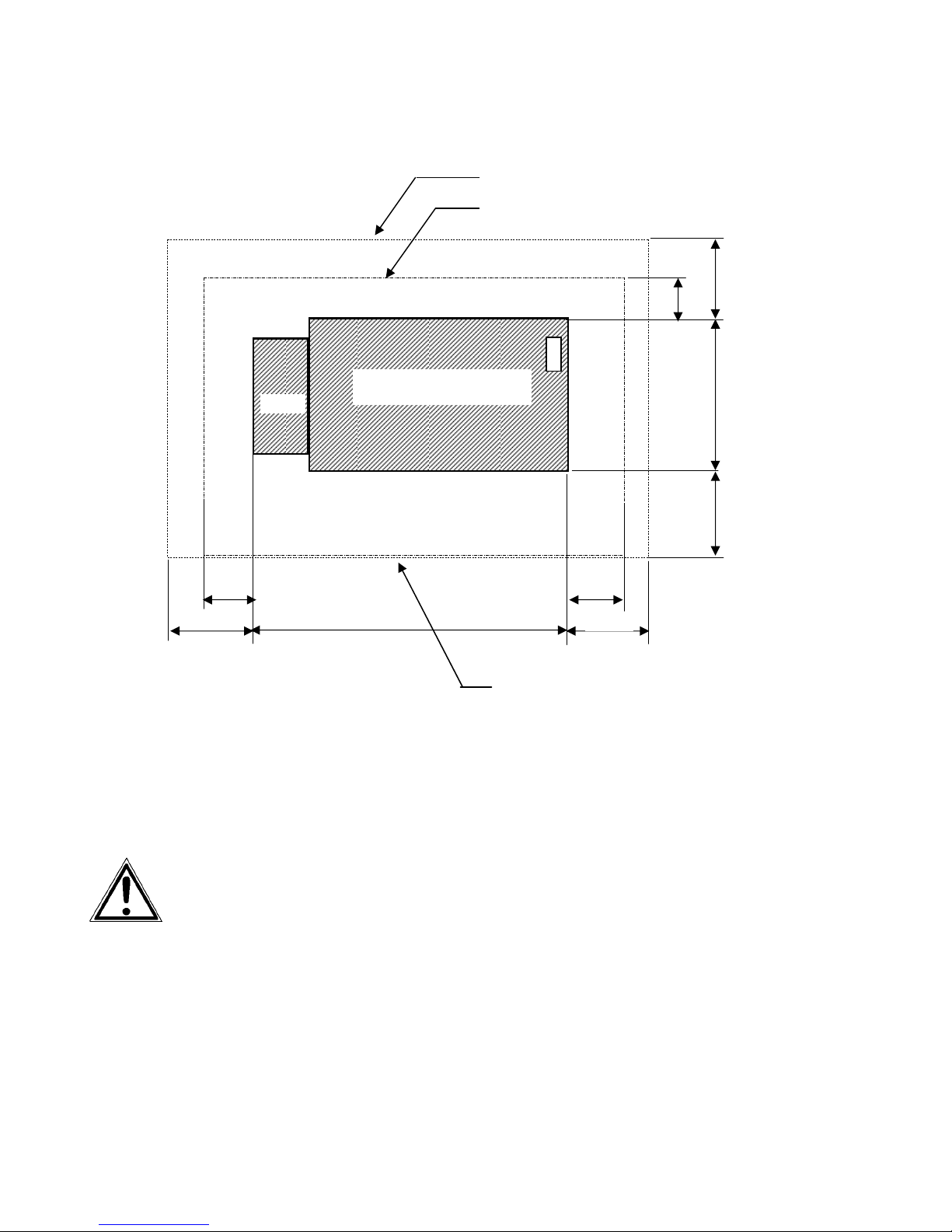
2.2. Printer Installation (Environment and Power Standards)
Space required for maintenance service
Stacker
Space required for usual printer operation
1 0 0 0
5 0 0
SOLID F90 HD
78 0
Front cover
800
1000
Fig. 2.2.a SOLID F90 HD: Required space (plan view)
1320
Space required when
front cover is open
- The chosen location should be well ventilated.
- Damaging environmental factors such as metal vapors, oil mist,
corroding lixivium or the like must not come in contact with the
printer.
- Position the printer on solid and level ground.
- Do not expose the printer to shocks or vibrations.
- The printer should not be located near volatile or combustible
materials (e.g. a curtain).
800
1000
1 0 0 0
( Unit : mm )
The printer’s first installation has to be done by a trained service
engineer.
!
_______________________________________________________________________________________________
MICROPLEX Operator’s Manual SOLID F90 HD Edition 1.0
Page 15

Installation 15
_______________________________________________________________________________________________
- Avoid locating the printer close to an air current ( e.g. ventilators).
- The printer should not be exposed to direct sunlight.
- Do not touch the drum surface because the material is easy to
damage.
- Do not expose the printer to abrupt temperature changes.
- In order to run the printer reliably, please maintain the following
environmental conditions:
Temperature: +15°C to +30°C (59°F to 86°F) operating
-10°C to +35°C (14°F to 95°F) non-operating
Relative humidity: 30% to 80% operating
10% to 80% non-operating
Power standards:
- Please connect the power plug to
230 V AC, 50 Hz (Europe, United Kingdom e.g.).
- The max. effective power input is appr. 5.5 kVA.
- The voltage support must not be impaired by interference.
- The printer is provided with a flexible 3x2.5 mm² connection cable
including a CEE plug 3x32. The corresponding CEE socket has to
be provided with a ≥25A fuse.
- If using an equivalent fixed connection ensure the grounding is
effected.
- Use the printer only within the allowable fluctuation range +10%
of the power voltage.
!
!
_______________________________________________________________________________________________
MICROPLEX Operator’s Manual SOLID F90 HD Edition 1.0
Conditional connection for the SOLID F90 HD:
The maximum permissible system impedance Z
The user of this device has to determine in consultation with the supply
authority, if necessary, that the equipment is connected only to a
supply of that impedance or less!
To avoid damage, the devices must be switched off (i.e. cut off
from the power supply) before the user begins connecting the
interface line.
is appr. 0.02 Ohm.
max
Page 16
16 Installation
_______________________________________________________________________________________________
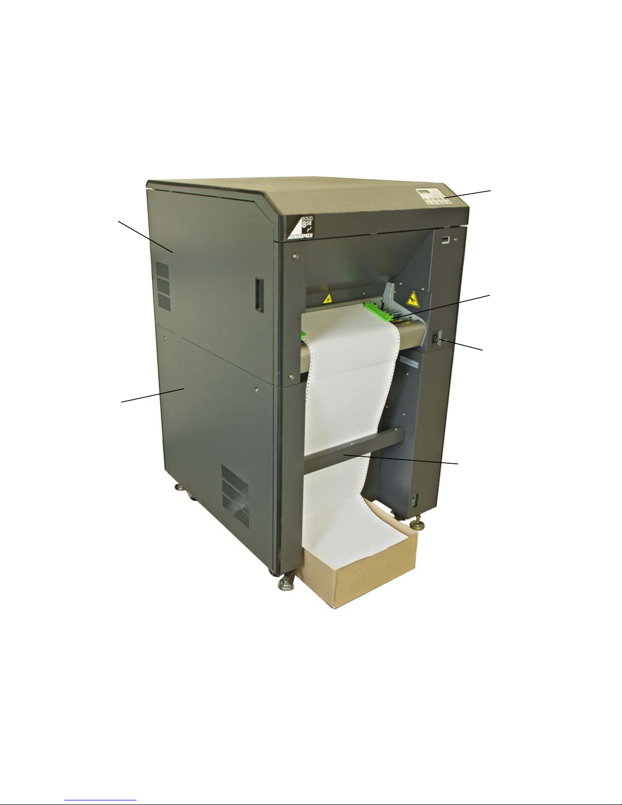
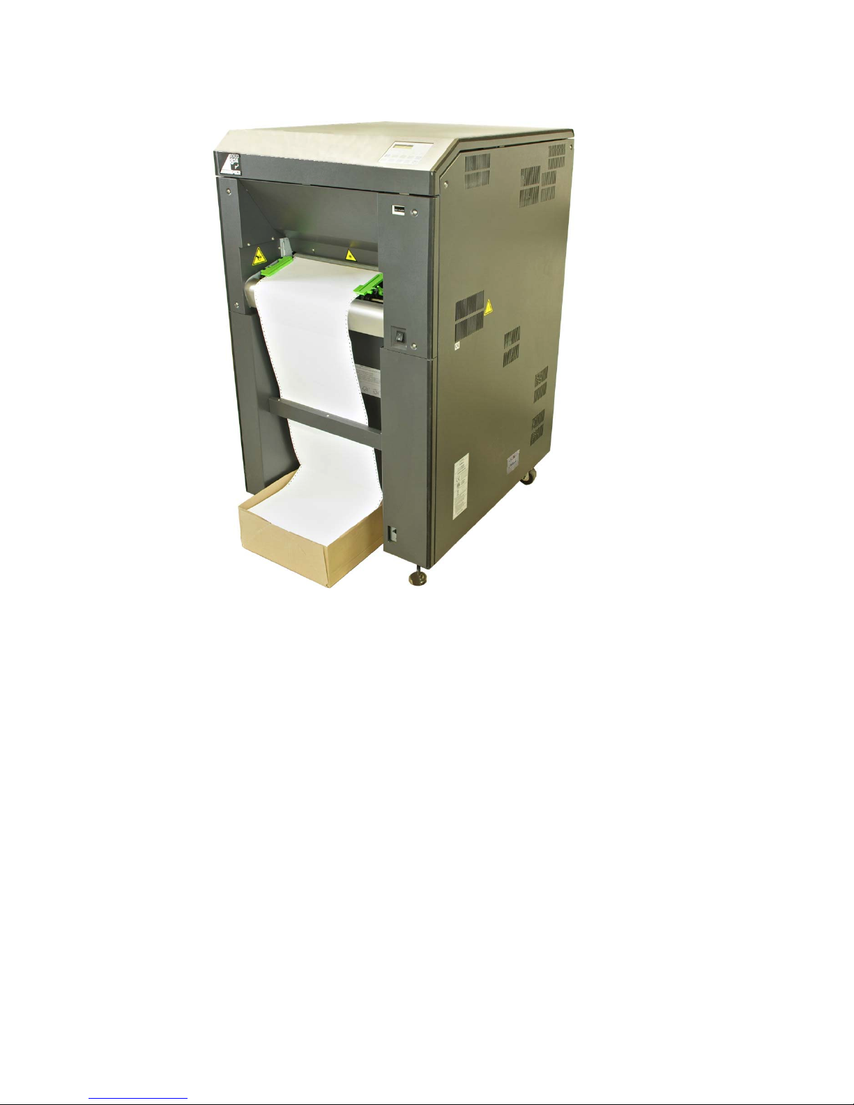
2.3. Printer Components
External Views:
Control
Front cover
panel
Tractor
Lower
Front cover
Power switch
Paper near end
sensor
_______________________________________________________________________________________________
MICROPLEX Operator’s Manual SOLID F90 HD Edition 1.0
Page 17
Installation 17
_______________________________________________________________________________________________
_______________________________________________________________________________________________
MICROPLEX Operator’s Manual SOLID F90 HD Edition 1.0
Page 18
18 Installation
_______________________________________________________________________________________________
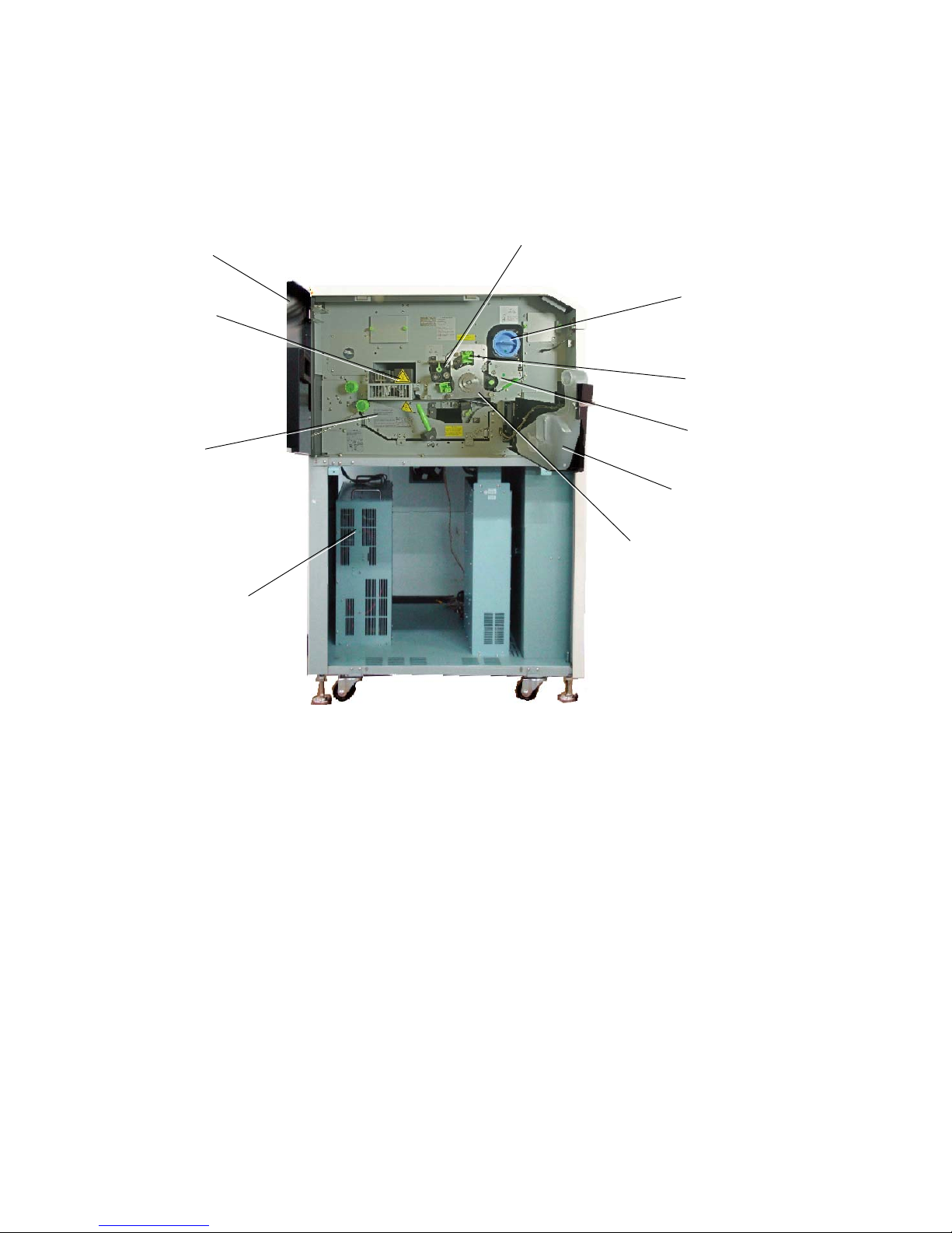
Printer interior view:
Front cover
Fuser unit
Transport
unit
Power supply
for flash lamp
Cleaning unit
Toner cartridge
Main charger
Developer unit
Waste toner
recovery unit
Drum plate
_______________________________________________________________________________________________
MICROPLEX Operator’s Manual SOLID F90 HD Edition 1.0
Page 19
Handling of Consumables 19
_______________________________________________________________________________________________
3. Handling of Consumables
3.1. Loading Paper
The printer processes continuous paper in lengths from 7 to 24
inches and width from 6 to 18 inches (including the perforated
!
!
margins, 17 inches printable).
You can check the printer configuration (inclusive the settings
regarding paper length etc.) by printing a status sheet (see
section 5.1).
If a large quantity of paper with a paper width smaller than
18 inch has been processed, the printer has to be cleaned first
before you start to process paper with a larger paper width.
See chapter 6 Printer Cleaning (especially section 6.2
Cleaning the Transport Unit) and chapter 7 Operator
Maintenance (especially section 7.1 Charger Cleaning).
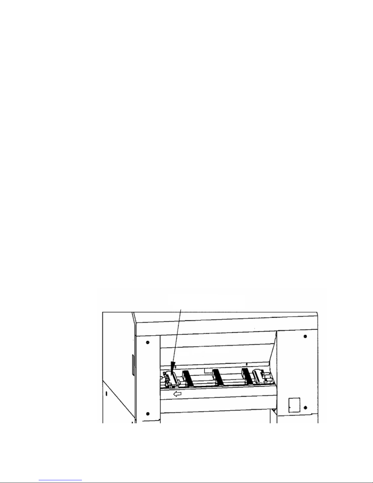
1. Turn the printer OFF LINE.
2. Make sure the left tractor is in the left position.
Left Tractor
_______________________________________________________________________________________________
MICROPLEX Operator’s Manual SOLID F90 HD Edition 1.0
Page 20
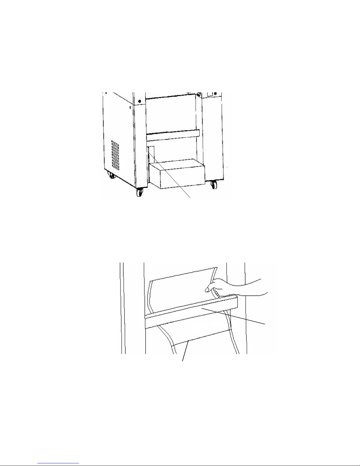
20 Handling of Consumables
_______________________________________________________________________________________________
3. Place the box containing the fanfold paper below the tractor
unit as shown below.
Mark for the left
paper margin
4. Pass the fanfold paper through the sensor guide (Paper
Near End Sensor PNES).
Guide with
paper sensor
Folded edge of the paper
_______________________________________________________________________________________________
MICROPLEX Operator’s Manual SOLID F90 HD Edition 1.0
Page 21
Handling of Consumables 21
_______________________________________________________________________________________________
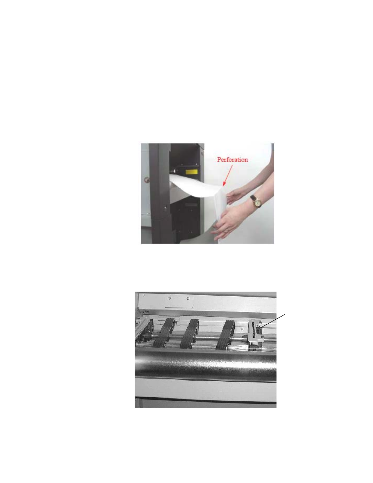
To avoid paper jams the first folded edge of the fanfold paper
(Perforation) has to point away from the printer. (If need be,
!
please tear off the first page of your fanfold paper to allow the
alignment shown in the following figure.)
In addition do not stretch the paper excessively and do not
allow any slack to avoid incorrect filing.
By this you can secure that the paper will be positioned right in
the stacker.
Preview: Fanfold paper loaded in the right way
5. Please unlock the right tractor. For that you have to turn the
6. Open the two tractor cover plates by turning them into the
upright position.
lever (tractor lock lever) of the right tractor
into the vertical position.
"
"
Lock lever
of the right
tractor
_______________________________________________________________________________________________
MICROPLEX Operator’s Manual SOLID F90 HD Edition 1.0
Page 22
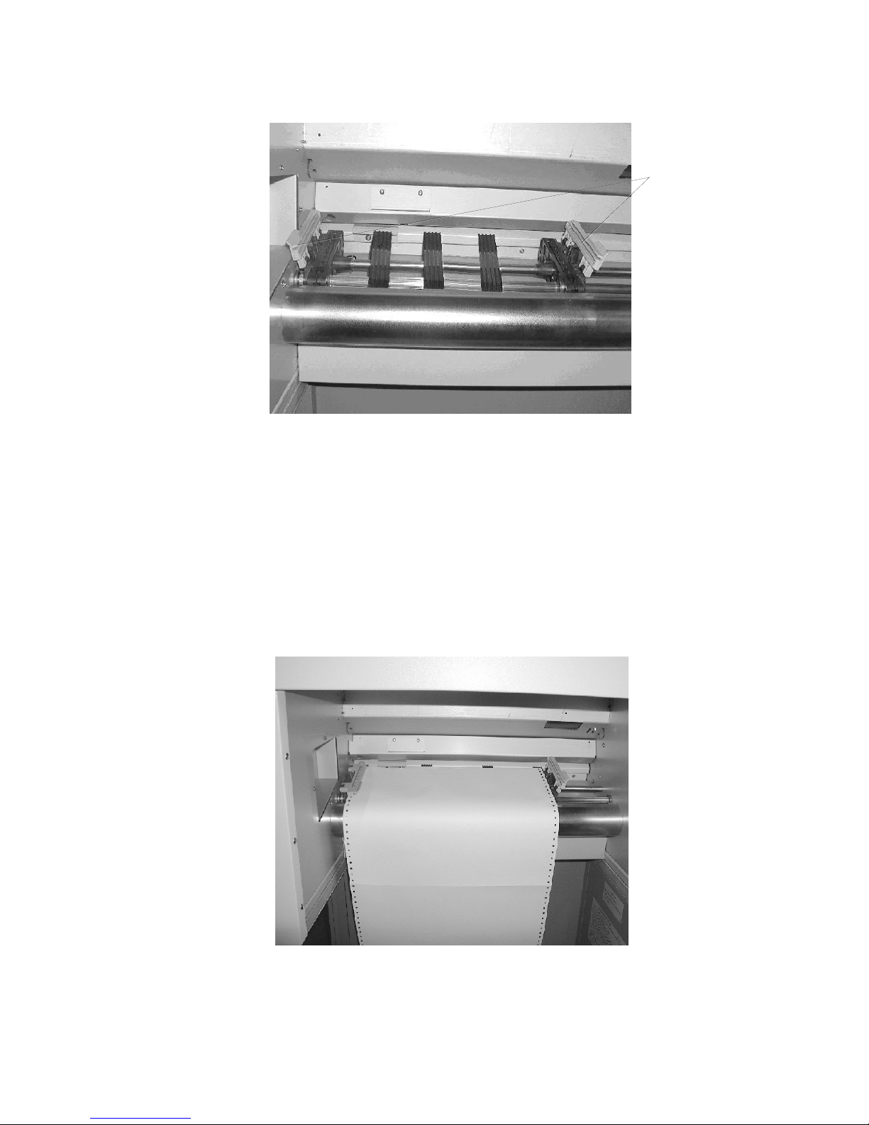
22 Handling of Consumables
_______________________________________________________________________________________________
Tractor
cover plates
7. Place the paper on the tractor pins on the left side. The paper
8. Spread out the tractor so that the sprocket holes on the right
#
perforation should be aligned over 4 or 5 tractor pins.
Close the left tractor cover plate.
side of the continuous paper can be placed easily onto the
tractor pins.
$
_______________________________________________________________________________________________
MICROPLEX Operator’s Manual SOLID F90 HD Edition 1.0
%
Page 23
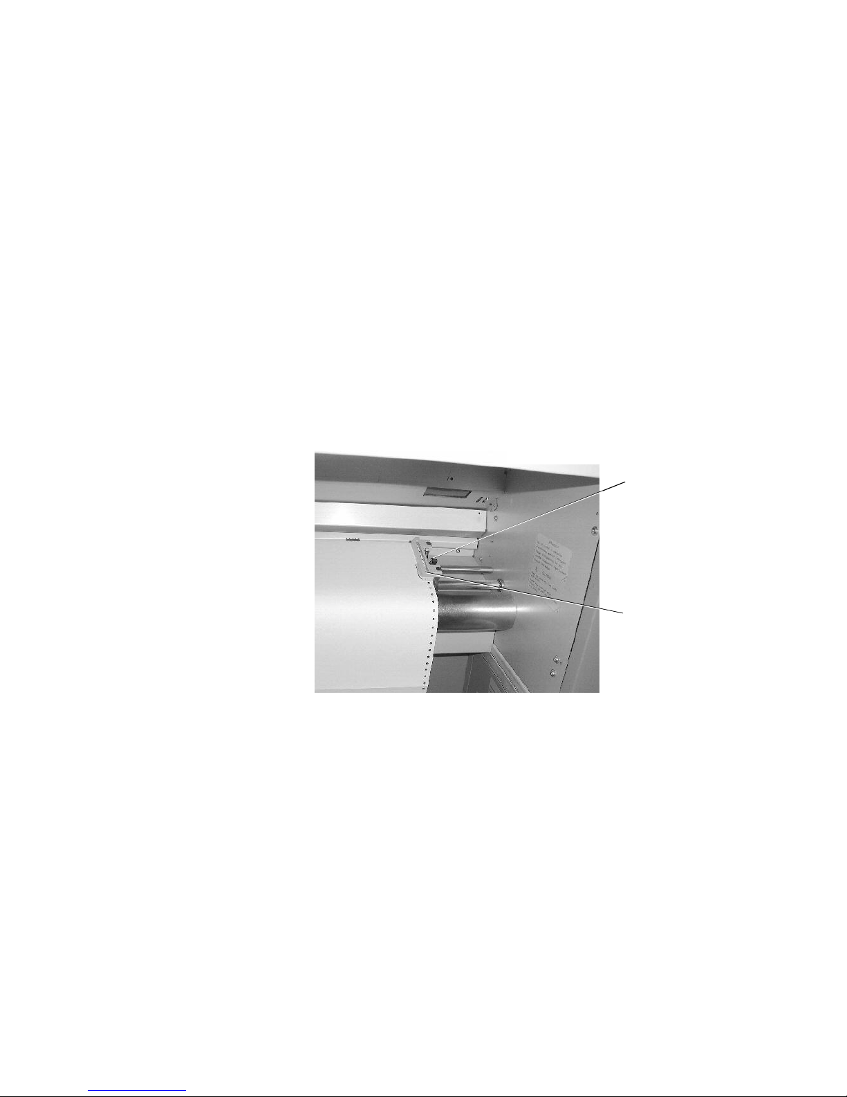
Handling of Consumables 23
_______________________________________________________________________________________________
The paper sensor in the middle of the tractor has to be covered by
the paper. On the other hand the paper must not reach into
the printer too far.
9. Close the right tractor cover plate and tighten the paper gently
with the right tractor.
To avoid paper jams the paper must not be inserted too lose
or too tight.
!
10. Lock the right tractor by using the lock lever.
Lock lever
of the right
tractor
&
Tractor cover
plate
11. Turn the printer ON LINE. The newly aligned paper
will be driven to the start position automatically.
12. If necessary adjust the printer to the new page length
(see section 5.9).
_______________________________________________________________________________________________
MICROPLEX Operator’s Manual SOLID F90 HD Edition 1.0
Page 24
24 Handling of Consumables
t
_______________________________________________________________________________________________
3.2. Replacing the Toner Cartridge
Please replace the toner cartridge, when the message [TONER
EMPTY!] is displayed.
With one toner filling approximately 20,000 pages A4 with a
print density of 5 % can be printed (compare chapter 10
Specifications).
Please wear vinyl gloves to avoid dirty hands when
replacing the cartridge.
!
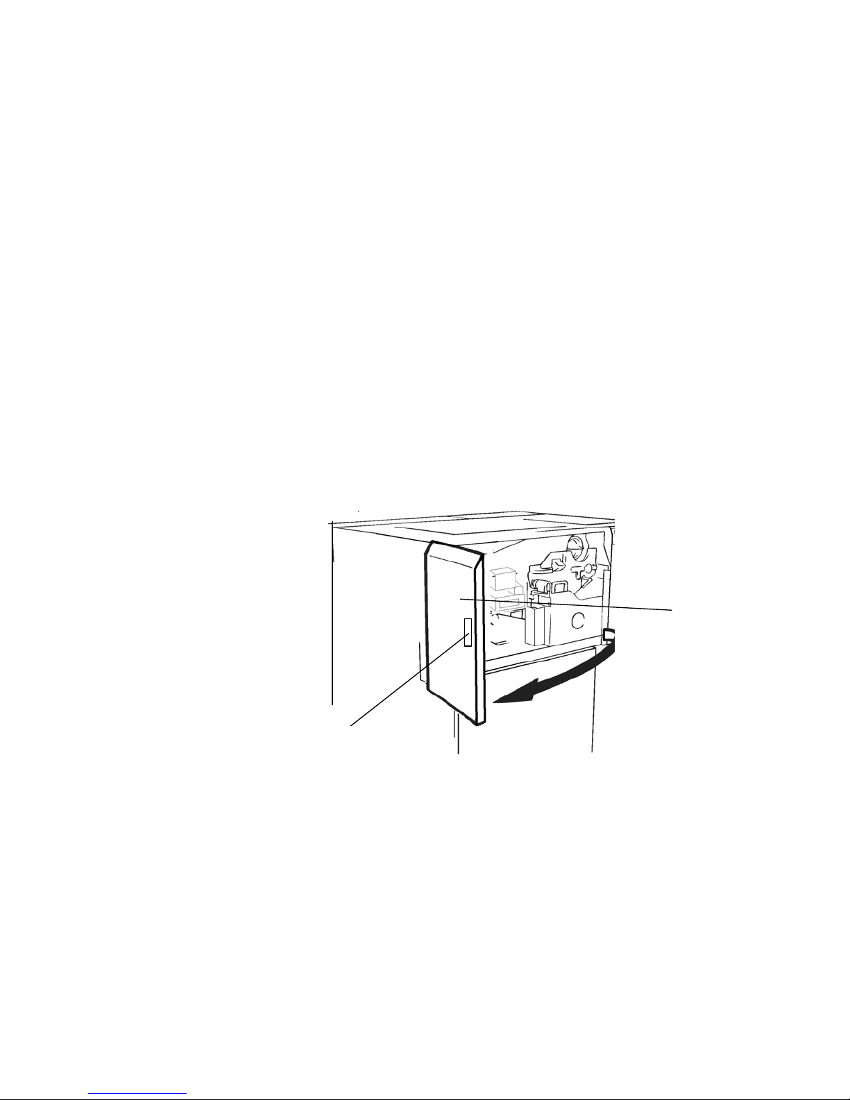
1. Open the front cover of the printer.
Handhold
Fron
cover
_______________________________________________________________________________________________
MICROPLEX Operator’s Manual SOLID F90 HD Edition 1.0
Page 25
Handling of Consumables 25
e
_______________________________________________________________________________________________
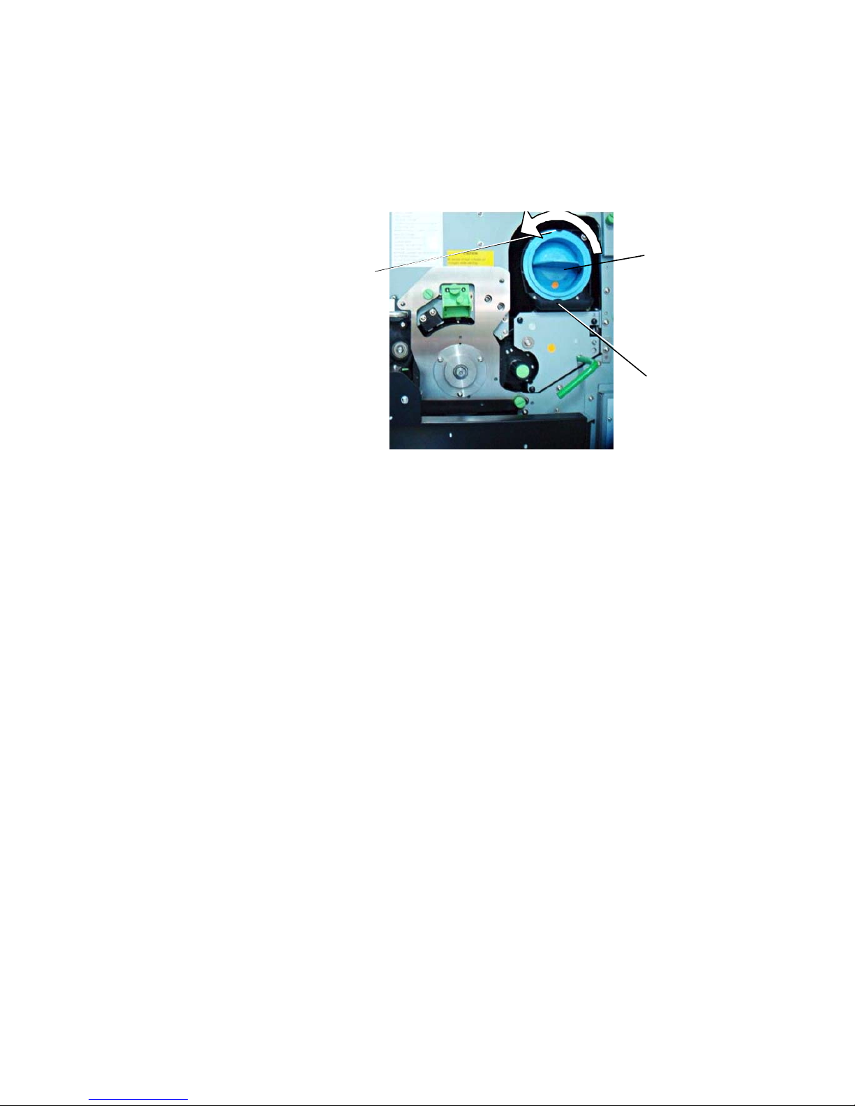
2. Rotate the used toner cartridge 180° counterclockwise
until it stops. Pull out the cartridge.
Toner cartridg
Slit
Pin
!
3. Take the new toner cartridge out of the packing. Use the
vinyl bag to pack the old cartridge.
On the occasion of every toner cartridge replacing the
necessity of cleaning the developer unit has to be checked.
Cleaning the developer unit has to be done in due time to
avoid reduced print quality (see section 7.2).
_______________________________________________________________________________________________
MICROPLEX Operator’s Manual SOLID F90 HD Edition 1.0
Page 26
26 Handling of Consumables
_______________________________________________________________________________________________
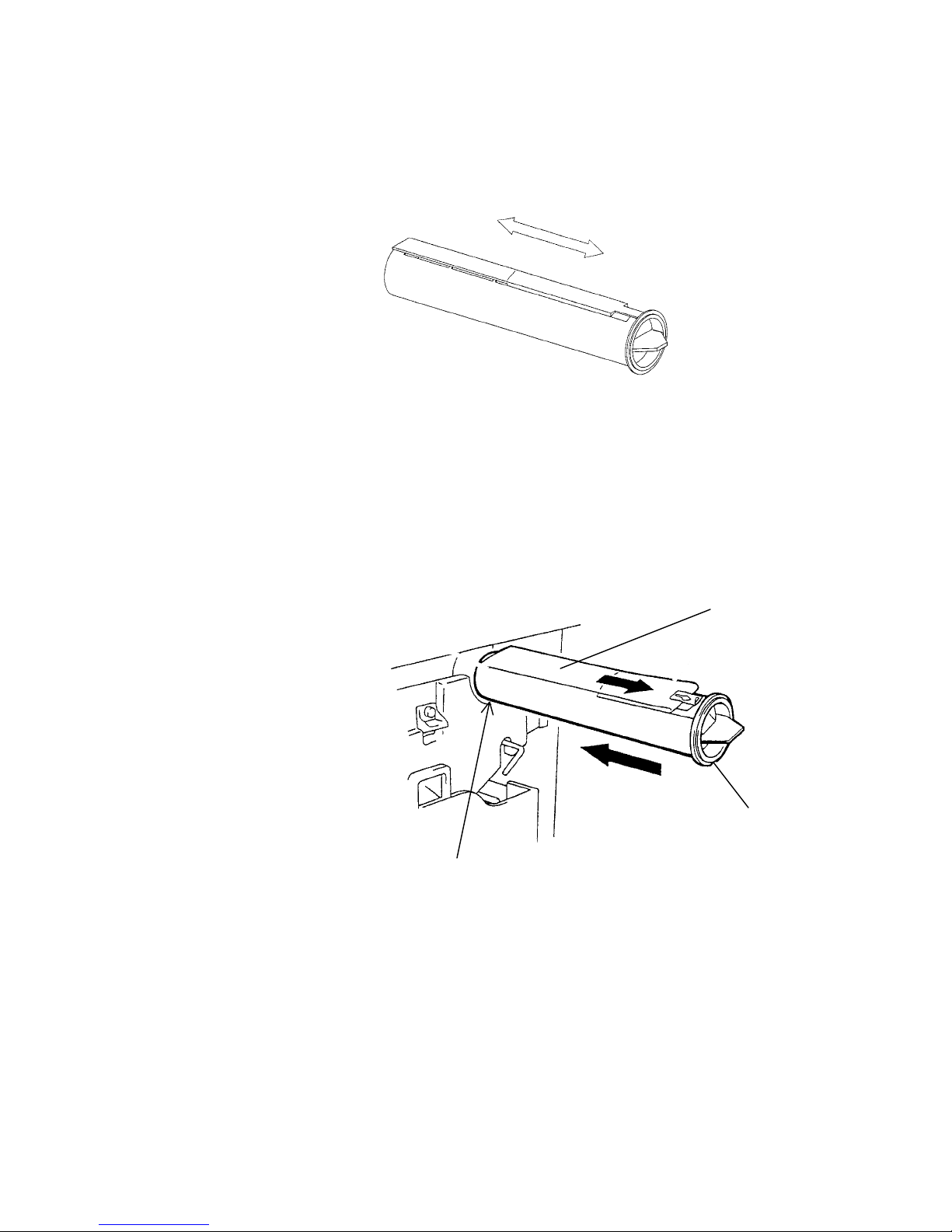
4. Shake the new cartridge gently by performing horizontal
movements to distribute the toner.
Put the end of the new cartridge into the SOLID F90 HD
5.
toner hopper with the adhesive tape facing up, and slowly
strip off the tape from the front to the back. Slide the
cartridge gently into the device in one operation.
Adhesive
tape
Slit
Pin
_______________________________________________________________________________________________
MICROPLEX Operator’s Manual SOLID F90 HD Edition 1.0
Page 27
Handling of Consumables 27
e
_______________________________________________________________________________________________
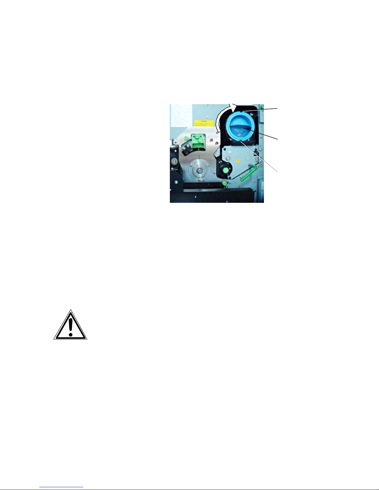
6. Insert the cartridge deeply into the toner hopper until it
stops. For that you have to align the toner cartridge slit
with the developing unit pin. Then slowly turn the
cartridge 180° clockwise.
Slit
(after the
rotation)
Toner cartridg
Pin
7. Close the printer’s front cover.
The announcement [TONER EMPTY!] will
be extinguished.
The toner is easily combustible and should never come in
contact with fire. Disposal will be carried out by your
service engineer. Until disposal please store the cartridge
in a vinyl bag in a closed cardboard box.
_______________________________________________________________________________________________
MICROPLEX Operator’s Manual SOLID F90 HD Edition 1.0
Page 28
28 Handling of Consumables
_______________________________________________________________________________________________
3.3. Replacing the Waste Toner Bottle
Replace the waste toner bottle when the announcement [TONER
WASTE!] occurs. On average, the bottle will be filled after
!
100,000 A4 pages have been printed.
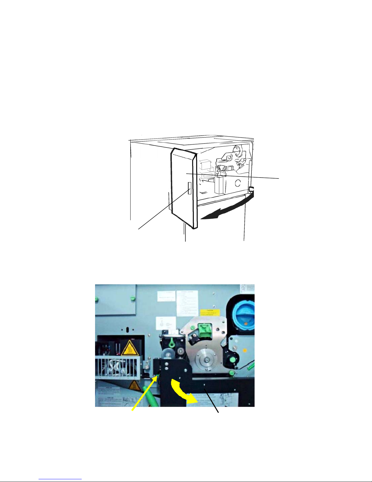
1. Open the front cover of the printer.
Front
cover
Handhold
2. Press down the open lever of the waste toner recovery unit
and open the unit.
Open lever (green)
_______________________________________________________________________________________________
MICROPLEX Operator’s Manual SOLID F90 HD Edition 1.0
Waste toner recovery unit
Page 29
Handling of Consumables 29
_______________________________________________________________________________________________
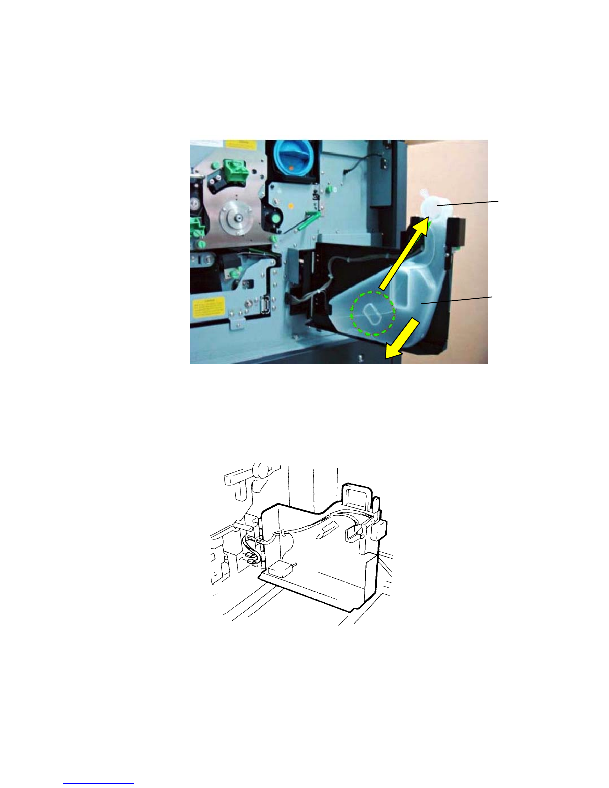
3. Take off the cap outside the waste toner recovery unit and
close the bottle.
Cap
Waste toner
bottle
4. Take out the waste toner bottle completely.
5. Insert the new bottle into the waste toner recovery unit.
_______________________________________________________________________________________________
MICROPLEX Operator’s Manual SOLID F90 HD Edition 1.0
Page 30

30 Handling of Consumables
_______________________________________________________________________________________________
Close the waste toner recovery unit. Make sure the bars click
into place.
!
6. Close the printer’s front cover.
The announcement [TONER WASTE!] will be
extinguished.
The waste toner is easily combusti
in contact with fire. Disposal will be carried out by your service
engineer. Until disposal please store the waste toner bottle in a
vinyl bag in a closed cardboard box.
ble and should never come
_______________________________________________________________________________________________
MICROPLEX Operator’s Manual SOLID F90 HD Edition 1.0
Page 31

Operation and Menu Structure 31
_______________________________________________________________________________________________
4. Operation and Menu Structure
4.1. Attaching the Printer to a Computer
1. Make sure the printer, computer, and any other attached devices
are turned off and unplugged.
Use a proper interface line to connect the printer to the computer or to
2.
attach the printer to the network.
The printer SOLID F90 HD is provided with several interfaces; see
chapter 10 Specifications for more information.
4.2. Printer Power on
The power switch is located at the right side of the printer (see section 2.3
Printer Components). As soon as the printer’s warm up phase is finished the
print system SOLID F90 HD goes into the ON LINE mode.
The Online LED and the Ready LED shine and the name of the printer is
displayed.
________________________________________________________________________________________________
MICROPLEX Operator’s Manual SOLID F90 HD Edition 1.0
Page 32
32 Operation and Menu Structure
_______________________________________________________________________________________________
4.3. Control Panel View
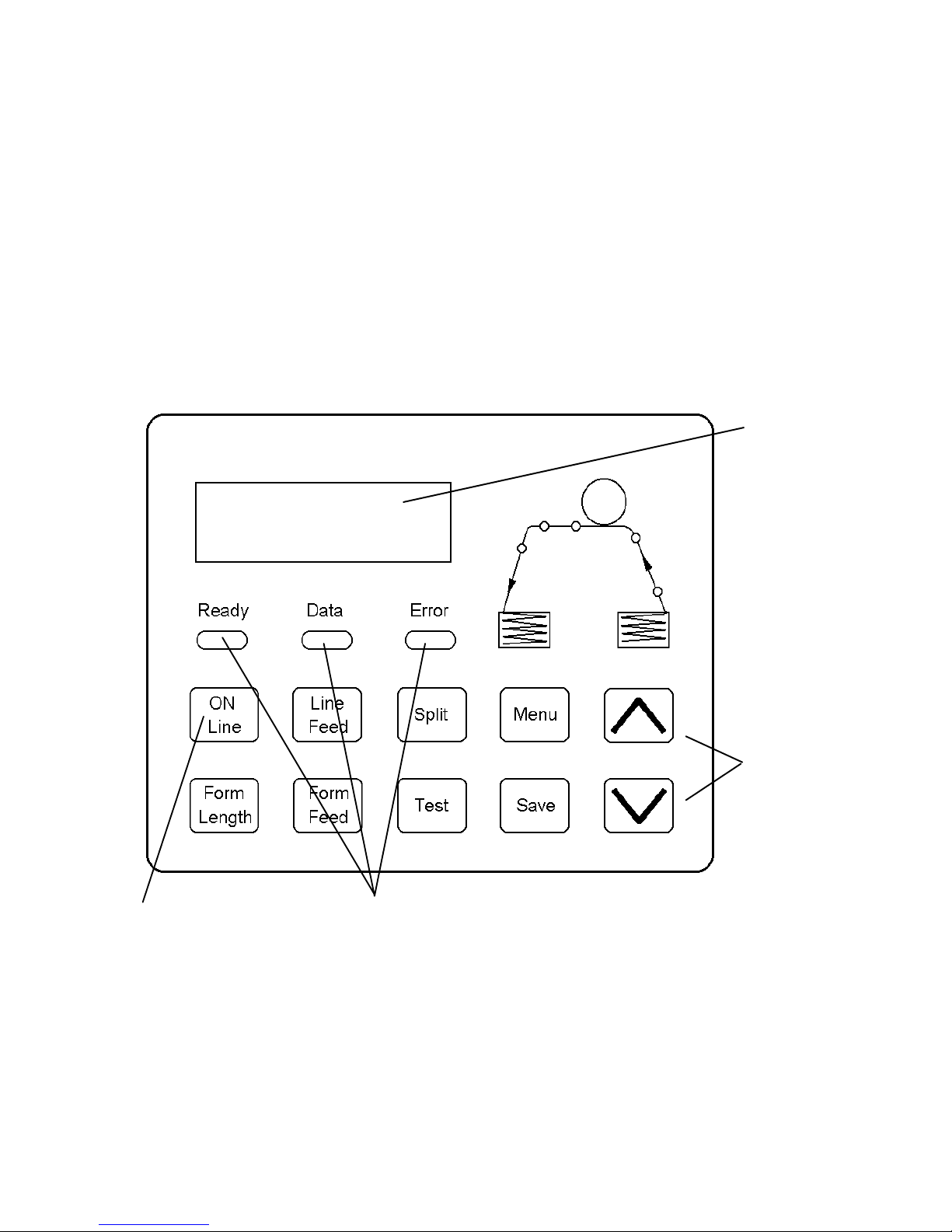
The control panel offers you:
• information about the actual state of the device (panel and LEDs).
• direct command input using the keyboard.
Display
(two-lined)
ON LINE
SOLID F90 HD
On / Off Line key
2 lines
of keys
LEDs
________________________________________________________________________________________________
MICROPLEX Operator’s Manual SOLID F90 HD Edition 1.0
Page 33
Operation and Menu Structure 33
_______________________________________________________________________________________________
4.4. Function of the Control Panel Elements
Display
The display (panel; 2 x 16 character LCD) serves to show the
printer’s messages.
LEDs
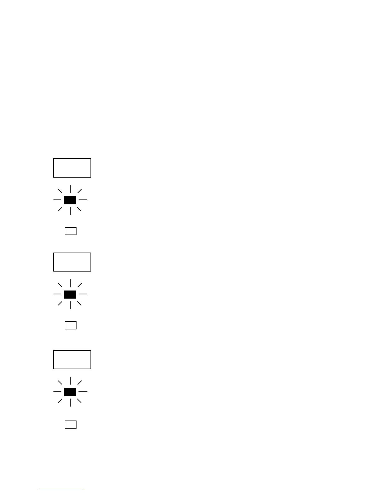
Meaning of the LED Announcements:
The printer control panel contains the following LEDs
(Light Emitting Diodes):
READY
The printer is ready to operate, initializing has been completed,
the photoreceptor drum is warmed up etc.
ERROR
DATA
The phase of initializing is not yet completed.
The printer receives printable data.
There are no printable data in the input buffer.
An error occurred in the printer. The printer is OFF LINE.
No error occurring.
________________________________________________________________________________________________
MICROPLEX Operator’s Manual SOLID F90 HD Edition 1.0
Page 34

34 Operation and Menu Structure
T
_______________________________________________________________________________________________
Control Panel Keys
ON LINE
FORM
LENGTH
!
LINE
FEED
This sy
printer ON LINE or OFF LINE.
The other control panel keys are only active in the OFF LINE mode.
The current form length is announced. The
20 inches can be selected in 1/6 inch steps.
The cutting device can only cut paper along the perforation, so
the set form length has to correspo
Wrong settings lead to paper jams.
Paper will be transported 1/6 inch forward.
mbol shows the ON LINE key. This key is used to turn the
form lengths from 7 to
nd with the current paper size.
FORM
FEED
SPLI
________________________________________________________________________________________________
MICROPLEX Operator’s Manual SOLID F90 HD Edition 1.0
After loadin
position. Apart from that activating the FORM FEED key in the OFF
LINE mode will move the paper one form length ahead.
The last print job will be cut at its end and the paper will be moved
to the park position.
g new paper the paper will be driven to the start
Page 35
Operation and Menu Structure 35
_______________________________________________________________________________________________
TEST
MENU
A status sheet will be printed (see section 5.1 Printing the
Status Sheet and section 5.8 Gene
These k
eys are used for working within the different levels of the
rating Test Prints, too).
menu structure described in the following chapters.
SAVE
________________________________________________________________________________________________
MICROPLEX Operator’s Manual SOLID F90 HD Edition 1.0
Page 36

36 Operation and Menu Structure
_______________________________________________________________________________________________
4.5. Configuration via the Control Panel
You can use the control panel to change the printer configuration
and customize your printer to meet your specific needs.
In addition printer configuration via Ethernet is possible.
The MICROPLEX printer controller offers an integrated website, for
more information see Networking Features of MICROPLEX Printers
Chapter 5 (Panel Functions) describes how to reach the particular
printer functions via the control panel.
T e m p o r a r y changes in printer configuration are effective only
as long as the printer stays turned on. To select such changes
temporarily, the user must terminate the change of function by
pressing the
SAVE key one single time.
.
P e r m a n e n t changes in printer configuration are active each
time the printer is turned on again. To select such changes
permanently, the user must terminate the change of function by
pressing the
SAVE key two times.
An output of the current printer values can be generated using the
“Status Sheet Printing“ panel function (see section 5.1).
Please note:
• User default settings remain in effect until you save new settings
or restore the factory defaults.
• Settings you choose from your software application or printer
driver can also change or overri
de the user default settings you
select from the touch panel.
________________________________________________________________________________________________
MICROPLEX Operator’s Manual SOLID F90 HD Edition 1.0
Page 37

Operation and Menu Structure 37
_______________________________________________________________________________________________
Switching the Printer OFF LINE
After the printer was turned on (and as soon as the warm up phase is
finished) the printer goes into the ON LINE — Mode.
[SOLID F90 HD ]
ON LINE
[Menu Level 1 ]
The display of the control panel shows the name of the printer.
This symbol shows the ON/OFF LINE key. If the printer is turned
OFF LINE with this key you get automatically into the first menu level.
Now this message is shown by the display of the control panel.
In the interest of simplicity, in the following chapters only the most
important display messages are shown in the Panel display column.
________________________________________________________________________________________________
MICROPLEX Operator’s Manual SOLID F90 HD Edition 1.0
Page 38
38 Operation and Menu Structure
t
r
-
n
r
t
r
t
m
Y
-
Y
-
'
T
d
-
Y
-
P
s
x
x
x
t
-
_______________________________________________________________________________________________
4.6. Menu Structure
Access to the menu structure is possible as soon as the printer is turned OFF
LINE. The SOLID F90 HD menu structure is arranged in different levels:
ON LI NE - Mode
OFF LINE
Men u L e vel 1
Paper Menu
Confi gur ati o
Page Menu
Engine
Networ k
Status Sheet
Font List
Hexdu mp
Prin
Files
Directory
Dump
/FF
Normal Pr i n
File Management
Cancel Job
Menu Page
Sliding Pattern
Buff e
Page Length
in mm
in inch
in 1/300 inch
Paper Width
in mm
in inch
in 1/300 inch
Two-Up Mode
Di r ec ti on
X-Direction
Print Direction
Interface
SIA Timeout
RS 232
RS 232 Protocol
RTS/CTS
XON/XOFF
None
Baudrate
RS 232 Fm.
Emu lat io n
Lang uage
Tra nsp arent Code
Input Buffe
Config. Word
User Config.
Font Numbe
Ori en tat i on
Symbol Code
Line Spacing
Char. Spacing
Line Termination
Mar gi n
Lef t
from Righ
Top
from Botto
PCL
Off se t
Nu mb e rO f Co pi es
Resolution
Pos.
Image X
Image
Pos.
Print Density
Format Check
Last Error
Service Mo
Timeout
IP Assign
Off
DHC
Manual
IP Addres
e
Subnet mask
Gateway
Persistant DHCP
Du pl ex /S pe ed
Au t on e g ot i a t i o n
10MB Half Duple
10MB FullDuple
100MB HalfDuplex
100MB FullDuple
This panel function allows the user to choose a reduced menu instead of
the extended menu shown above.
________________________________________________________________________________________________
MICROPLEX Operator’s Manual SOLID F90 HD Edition 1.0
Selec
Define
Factory Default
RF M
Key lock
Ext ended Menu
ime Setting
Date Setting
Page 39

Operation and Menu Structure 39
_______________________________________________________________________________________________
Selecting positions in the menu structure:
ON LINE
[“Menu Level“]
This symbol shows t
he ON/OFF LINE key. You get automatically
into the first menu level, if the printer is turned OFF LINE with this
key.
These symbols show the ARROW keys. By pressing the UP arrow
or the DOWN arrow you can move within the menu levels.
Press and hold the UP key to scroll forward or the DOWN key to
scroll backward (to ch
ange numerical values, for example).
Each menu item/sub-item within a menu level is shown in the
ay of the control panel.
displ
SAVE
The SA
a particular menu and, once in the menu, it allows the user to
VE key has two main functions. It gives the user access to
select a particular function.
[“Function“]
________________________________________________________________________________________________
MICROPLEX Operator’s Manual SOLID F90 HD Edition 1.0
Page 40
40 Operation and Menu Structure
_______________________________________________________________________________________________
Functions / Changing of function values:
Within one function the value can be changed by pressing the
ARROW ke
In case of a multi-digit function value the value of the currently chosen
digit will be changed.
ys.
SAVE
MENU
SAVE
In case of a multi-digit function value pressing the SAVE key switches
to the next position of the function value.
Pressing the MENU key switches to the previous digit of the function
value.
Please note: If you press the MENU key although the absolute left
digit of the function value is still arrived, the changing
procedure will be cancelled and this moves you to the
next menu level above.
If you press the SAVE key although the absolute right
digit (digit 1) of the function value is still arrived, the
currently displayed function value is stored.
Pressing the SAVE key the currentl
y displayed function value is
confirmed respectively the displayed function is activated. The
changes are stored temporary. (This means, the changes are saved
only until the next printer power off).
[Save as Setup? ]
After this you have to decide, if you want to save the changes
permanent (Save as setup).
To select such changes permanently, the
SAVE
one more time. These permanent changes in printer configuration are
active each time the printer is turned on again.
If the MENU key is pressed instead, the cha
MENU
temporary (not saved as setup). (This key takes the user to the
respective previous menu level).
________________________________________________________________________________________________
MICROPLEX Operator’s Manual SOLID F90 HD Edition 1.0
user must press the SAVE key
nges are only stored
Page 41

Operation and Menu Structure 41
_______________________________________________________________________________________________
Return to the menu level above:
MENU
Return to the ON LINE mode:
ON LINE
Pressing the MENU key takes the user back to the respective
menu level above.
Pressing the ON LINE key switches the user directly to
″ON LINE″ from any menu position.
________________________________________________________________________________________________
MICROPLEX Operator’s Manual SOLID F90 HD Edition 1.0
Page 42

42 Operation and Menu Structure
_______________________________________________________________________________________________
4.7. Syntax of Diagrams
The control panel functions will be described using diagrams.
These diagrams show the course necessary in order to activate
a certain function.
Key A
Key B
Key C
["Message"]
First the elements of the diagrams
are explained:
The sequence on the left describes which keys have to be
pressed briefly in succession.
In this example key A has to be pressed first. Then key A is
released and key B has to be pressed. Then key B has to be
released and key C has to be pressed.
″Panel display″ column shows the display messages
The
corresponding to the sequences listed on the left.
In the column
steps are given.
________________________________________________________________________________________________
MICROPLEX Operator’s Manual SOLID F90 HD Edition 1.0
″Notes″ explanations to particular operational
Page 43

Panel Functions 43
_______________________________________________________________________________________________
5. Panel Functions
For the panel functions described in the following, the printer is
presumed to be turned on and in the ON LINE mode.
!
5.1. Printing the Status Sheet
This function generates a status sheet.
The status sheet contains information about the current printer
configuration and the available fonts.
ON LINE
SAVE
SAVE
ON LINE
Panel display
[SOLID F90 HD ]
[Menu Level 1 ]
[Status Sheet ]
[Status Sheet ]
Notes
Turn the printer OFF LINE with this
key.
Press the SAVE key. Menu level 1 is
selected.
Press the SAVE key again.
A status sheet is printed.
The printer is turned ON LINE
again.
________________________________________________________________________________________________
MICROPLEX Operator’s Manual SOLID F90 HD Edition 1.0
Page 44

44 Panel Functions
_______________________________________________________________________________________________
Status sheet contents:
The first lines, entitled SERVICE INFORMATION, contain
hexadecimal coded configuration parameters.
Printed in plain text:
-
Controller version / memory / serial number
-
Firmware release
-
Interface
parameters of Parallel, Serial, USB, Network (Ethernet)
-
Network
parameters and addresses
-
Printer emulation
-
User-RAM / free User-RAM
-
Input data buffer
-
Transparent code
-
Paper size
-
Default margins top / left
bottom / right
-
Default character code
-
Options
-
Fonts installed (Font banks)
Note:
Use the panel function Printing the Font List to show the fonts installed
(see the following section).
________________________________________________________________________________________________
MICROPLEX Operator’s Manual SOLID F90 HD Edition 1.0
Page 45

Panel Functions 45
_______________________________________________________________________________________________
5.2. Printing the Font List
This function generates a list of all fonts installed to the printer.
The font list shows demo prints of all fonts and, in addition, the
concerning PCL selection commands. These commands contain
information on font width and font height (see section 5.19
Font Selection, too).
ON LINE
Panel display
[SOLID F90 HD ]
[Menu Level 1 ]
Notes
Turn the printer OFF LINE with this
key.
SAVE
SAVE
ON LINE
[Status Sheet
( ( (
[Font List
]
[Font List ]
Menu Level 1 is selected.
]
Press one of the ARROW keys until
[Font List ] is displayed.
The font list is printed.
The printer is turned ON LINE
again.
________________________________________________________________________________________________
MICROPLEX Operator’s Manual SOLID F90 HD Edition 1.0
Page 46

46 Panel Functions
_______________________________________________________________________________________________
5.3. Choosing Print Resolution
This function allows the user to choose the current print
resolution.
If, after a particular resolution is chosen, the print data stream
indicates a different resolution (e.g. via a WINDOWS print
driver), the second print resolution will be used only for that job.
ON LINE
SAVE
SAVE
Panel displ
ay
[SOLID F90 HD ]
[Menu Level 1
( ( (
]
[Engine ]
[Resolution ]
[300 dpi ]
( ( (
Notes
Turn the printer OFF LINE with this
key.
Press one of the ARROW keys until
[Engine ] is displ
ayed.
Menu item Engine is selected.
Menu item Resolution is selected.
Press one of the ARROW keys until
the desired Resolution (e.g. 600
ots per inch) is displayed.
d
[600 dpi ]
SAVE
[Save as Setup? ]
MENU
________________________________________________________________________________________________
SAVE
ON LINE
MICROPLEX Operator’s Manual SOLID F90 HD Edition 1.0
600 dpi resolution is selected.
In addition this new value can be
saved as setup value (
using the
SAVE key), before the printer is
turned ON LINE again.
Page 47

Panel Functions 47
_______________________________________________________________________________________________
Remarks on choosing print resolution (Fonts):
By selecting 300 dpi resolution the printing system will be
compatible for all applications (300 dpi data stream), also the
300 dpi font banks (bitmap writing) are available.
If 600 dpi resolution is chosen, the corresponding fonts must
be loaded into the printer server (e.g. True Type fonts, scalable
download fonts).
________________________________________________________________________________________________
MICROPLEX Operator’s Manual SOLID F90 HD Edition 1.0
Page 48

48 Panel Functions
_______________________________________________________________________________________________
5.4. Hexdump Mode Activation
Within the Hexdump Mode the printer prints all characters received
via interface without any interpretation (hexadecimal coded).
This mode helps with error diagnosis. The Hexdump Mode can be
activated only temporarily.
ON LINE
SAVE
SAVE
Panel display
[SOLID F90
HD ]
[Menu Level 1 ]
[Status Sheet ]
( ( (
[Hexdump ]
[Hexdump ]
Notes
Turn the printer OFF LINE with this
key.
Menu level 1 is selected.
Press one of the ARROW keys until
[Hexdump ] is displaye
d.
The Hexdump Mode is activated.
ON LINE
Note:
By activating the normal print mode (see next section) or by
turning the printer off and on again the printer can be taken out of
Hexdump Mode.
Time between turning the printer off and on again should be at least
15 seconds.
________________________________________________________________________________________________
MICROPLEX Operator’s Manual SOLID F90 HD Edition 1.0
The printer is turned ON LINE
again.
Page 49
Panel Functions 49
_______________________________________________________________________________________________
5.5. Normal Print Mode Activation (incl. FORM FEED)
The normal print mode suspends the Hexdump Mode.
This function is activated, when a print job must be continued
without turning the printer off and on again. In addition to that the
function “Normal Print Mode Activation“ is used to produce a
FORM FEED.
ON LINE
SAVE
SAVE
Panel display
[SOLID F90
HD ]
[Menu Level 1 ]
[Status Sheet ]
( ( (
[Normal Print/FF ]
[Normal Print/FF ]
Notes
Turn the printer OFF LINE with this
key.
Menu level 1 is selected.
Press one of the ARROW keys until
[Normal Print/FF ] is displayed.
The normal print mode is activated.
ON LINE
Note:
After activating the normal print mode a FOR
automatically and one sheet is put out.
This is necessary because after a test in the Hexdump Mode it is
possible that data can remain in the input buffer unintentionally
(cause: in the Hexdump Mode no control characters are evaluated
and no FORM FEED
________________________________________________________________________________________________
MICROPLEX Operator’s Manual SOLID F90 HD Edition 1.0
is effected).
The printer is turned ON LINE
again.
M FEED
is released
Page 50

50 Panel Functions
_______________________________________________________________________________________________
5.6. Clearing the Input Buffer (Cancel Job)
This function permits the resumption of a print job at a
particular page after a print interruption (e.g. paper jam). The
data contained in the input buffer before the interruption are
cleared.
ON LINE
SAVE
SAVE
Panel display
[SOLID F90 HD ]
[Menu Level 1 ]
[Status Sheet ]
( ( (
[Cancel Job ]
[Cancel Job ]
Notes
Turn the printer OFF LINE with this
key.
Menu level 1 is selected.
Press one of the ARROW keys until
[Cancel Jo
b ] is displayed.
All data contained in the input buffer
will be cle
ared.
ON LINE
________________________________________________________________________________________________
MICROPLEX Operator’s Manual SOLID F90 HD Edition 1.0
The printer is turned ON LINE
again.
Page 51
Panel Functions 51
_______________________________________________________________________________________________
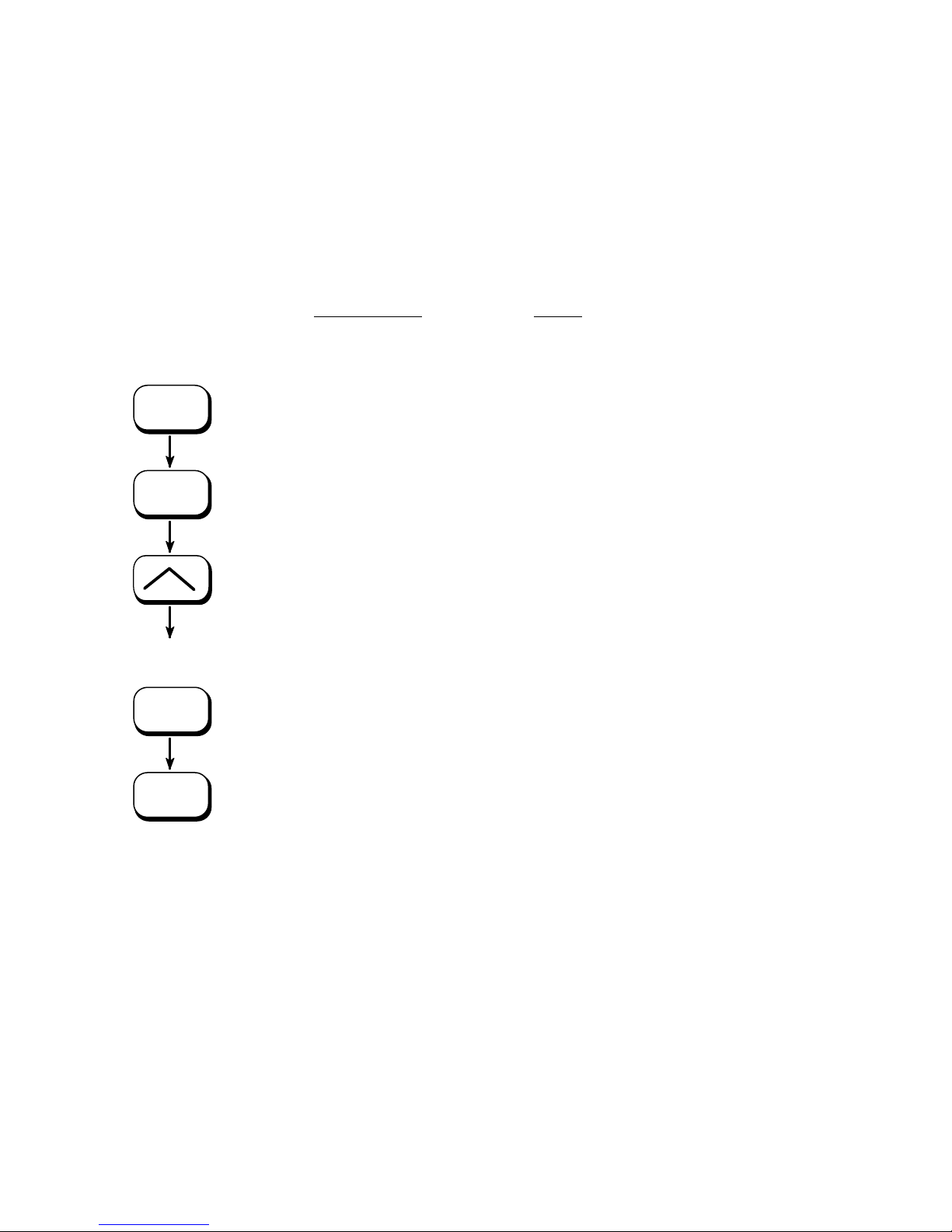
5.7. Printing the Menu Page
This function prints a survey of the available panel functions.
Note: When printing the menu page please use a large paper.
ON LINE
SAVE
SAVE
Panel display
[SOLID F90 HD ]
[Menu Level 1 ]
[Status Sheet ]
( ( (
[Menu Page ]
[Menu Page ]
Notes
Turn the printer OFF LINE with this
key.
Menu level 1 is selected.
Press one of the ARROW keys until
[Menu Page ] is displayed.
A menu structure presentation of
the SOLID F90 HD (see section 4.6)
is printed.
ON LINE
________________________________________________________________________________________________
MICROPLEX Operator’s Manual SOLID F90 HD Edition 1.0
The printer is turned ON LINE
again.
Page 52

52 Panel Functions
_______________________________________________________________________________________________
5.8. Generating Test Prints (Sliding Pattern)
This function generates a series of test prints without sending
data to the printer.
These test prints facilitate error analysis.
Panel display
[SOLID F90
ON LINE
TEST
ON LINE
HD ]
[Menu Level 1 ]
[Menu Level 1
]
Another way to activate the function:
see the following page !
Notes
Turn the printer OFF LINE with this
key.
A status sheet is generated
(possibly pr
The printer is turned ON LINE
again.
inted on several pages)
________________________________________________________________________________________________
MICROPLEX Operator’s Manual SOLID F90 HD Edition 1.0
Page 53
Panel Functions 53
_______________________________________________________________________________________________
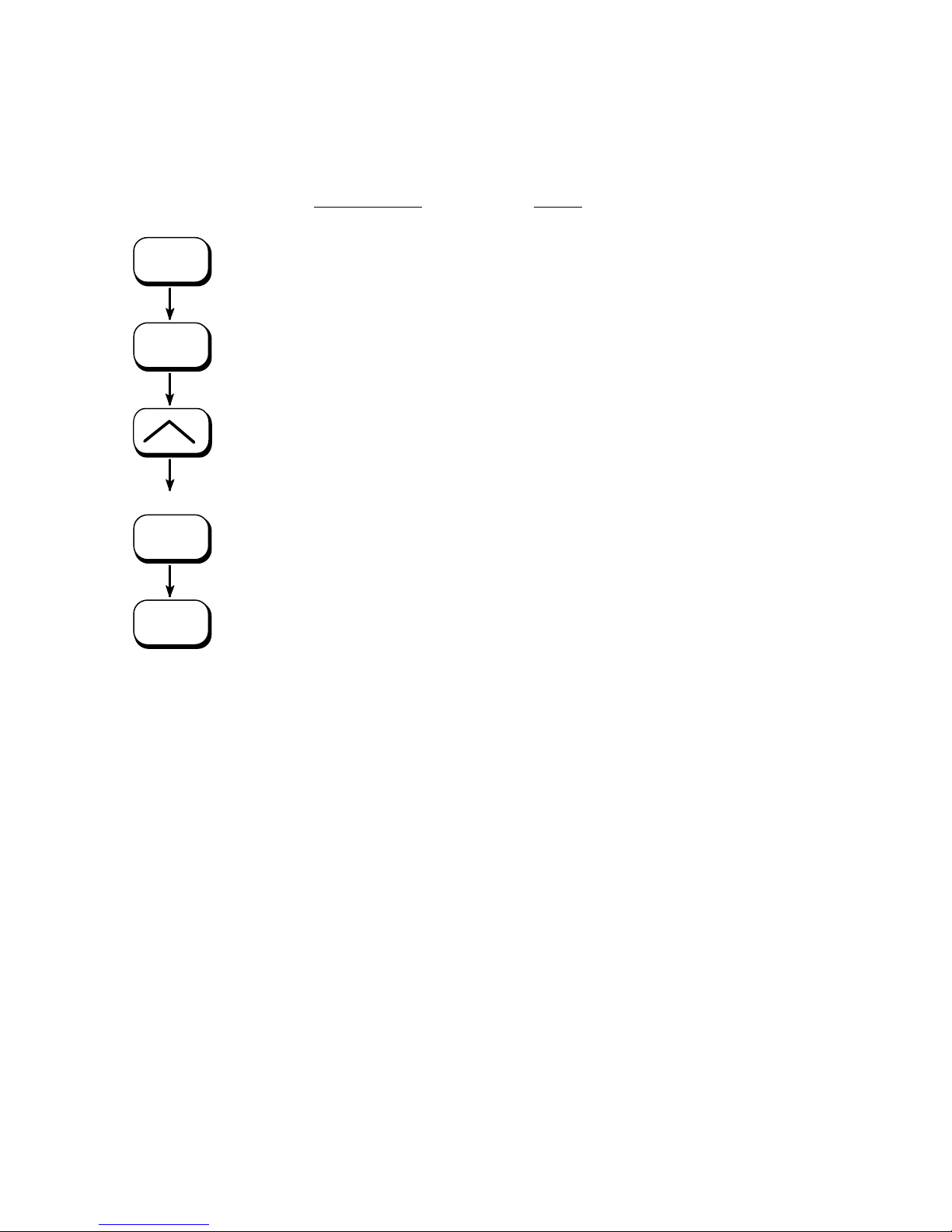
ON LINE
SAVE
SAVE
ON LINE
Panel display
[SOLID F90 HD ]
[Menu Level 1 ]
[Status Sheet
( ( (
[Sliding Pattern
[Sliding Pattern ]
]
]
Notes
Turn the printer OFF LINE with this
key.
Menu level 1 is selected.
Press one of the ARROW keys until
[Sliding Pattern ] is displayed.
A series of test prints is generated.
The printer is turned ON LINE
again.
The printing out of test prints can be stopped by pushing the
ON LINE k
ey.
!
________________________________________________________________________________________________
MICROPLEX Operator’s Manual SOLID F90 HD Edition 1.0
Page 54

54 Panel Functions
_______________________________________________________________________________________________
5.9. Page Length Adjustment
After inserting new material (e.g. paper) this function is used to
adjust the printer to the new page length. The default page length
value is 12 inches for Europe, 11 inches for North America.
ON LINE
SAVE
SAVE
SAVE
Panel displ
ay
[SOLID F90 HD ]
[Menu Level 1 ]
( ( (
[Paper Menu ]
[Stacker Select ]
( ( (
[Page Length ]
[in Inch ]
( ( (
Notes
Turn the printer OFF LINE with this key.
Press one of the ARROW keys until
[Paper Menu ] is displayed.
Press the SAVE key to select the paper menu.
Press one of the ARROW keys until
[Page Length ] is displayed.
Press the SAVE key to adjust the page length.
Inch = currently selected measuring unit
(alternat
ive the measuring units mm or 1/300
inch can be chosen with the ARROW keys).
[Digit4 1
( ( (
[Digit1 12.33
SAVE
[Save as Setup? ]
MENU
________________________________________________________________________________________________
SAVE
ON LINE
MICROPLEX Operator’s Manual SOLID F90 HD Edition 1.0
2.00 ]
]
Pressing one of the ARROW keys changes the
value of the current position (Digit 4 = left
digit, in this example: 1).
Pressing t
he SAVE key moves you to the next
digit (the MENU key moves you back).
Values from 7 to 24 inches are settable.
The page length is changed to 12.33 inches.
In addition this new value can be saved as
setup value
(using the SAVE key), before the
printer is turned ON LINE again.
Page 55

Panel Functions 55
_______________________________________________________________________________________________
Note If the option ‘Paper Request’ is chosen (by the following change of
configuration: CONFIG 32: Bit 2 set to 1), the printer goes OFF LINE
not only in case of paper end, but also after every printer turn on and
after every paper size adjustment, too.
The panel display shows the message [Load Paper ] ... .
After loading the corresponding paper the printer is turned ON LINE
by using the ON LINE key.
________________________________________________________________________________________________
MICROPLEX Operator’s Manual SOLID F90 HD Edition 1.0
Page 56

56 Panel Functions
_______________________________________________________________________________________________
5.10. Selecting the Number of Printpages per Page Format (Two-Up Mode)
Activating this function determines the arrangement of several
printpages per page format (paper width resp. page length).
ON LINE
SAVE
SAVE
SAVE
Panel displ
ay
[SOLID F90 HD ]
[Menu Level 1 ]
( ( (
[Paper Menu ]
[Stacker Select ]
( ( (
[Two-Up Mode ]
[Y-Direction ]
( ( (
[X-Direction ]
[X-Direction: OFF ]
( ( (
Notes
Turn the printer OFF LINE with this key.
Press one of the ARROW keys until
[Paper Menu ] is displayed.
Press the SAVE key to select the p
aper
menu.
Press one of the ARROW keys until
[Two-Up Mode
] is displayed.
Press the SAVE key to select the function
Two-Up mode.
Press one o
f the ARROW keys to effect
the adjustment of the Two-Up mode to the
X-direction (cross to the print direction).
Press the SAVE key to set the Two-Up
mode.
By pressing the ARROW UP or DOWN
key the
number of print pages cross to the
print direction can be altered. The
maximum number of print pages being
adjustable next to each other is 9.
[X-Direction: 2 ]
SAVE
[Save as Setup? ]
MENU
________________________________________________________________________________________________
SAVE
ON LINE
MICROPLEX Operator’s Manual SOLID F90 HD Edition 1.0
Here the number of print pages per
format widt
h was altered to 2.
In addition this new value can be saved
as setup value (using the SAVE
key),
before the printer is turned ON LINE
again.
Page 57

Panel Functions 57
A
_______________________________________________________________________________________________
Example:
The printer SOLID F90 HD processes fanfold paper with a width up
to 18 inches (17” printable). When the Two-Up mode is chosen,
each time 2 images of A4 are printed side by side.
print print
image 1 image 2
A4
form width
A4
3 landscape
print direction
(paper feed direction)
Note: All other page parameters have to be set optionally in accordance to the
requirements.
A simultaneous combination of several print images per formlength and
several print images per form width isn’t possible until now.
________________________________________________________________________________________________
MICROPLEX Operator’s Manual SOLID F90 HD Edition 1.0
Page 58

58 Panel Functions
_______________________________________________________________________________________________
5.11. Paper Width Adjusting (Format Width)
This function is used to adjust the format width (print width) to the
actually used paper format.
ON LINE
SAVE
SAVE
SAVE
Panel display
[SOLID F90
HD ]
[Menu Level 1 ]
( ( (
[Paper Menu ]
[Stacker Select ]
( ( (
[Paper Width ]
[in inch ]
( ( (
Notes
Turn the printer OFF LINE with this key.
Press one of the ARROW keys until
[Paper Menu ] is displayed.
Press the SAVE key to select the p
aper
menu.
Press one of the ARROW keys until
[Paper Width
] is displayed.
Press the SAVE key to adjust the format
width to the paper widt
h.
Inch = currently selected measuring unit
(alternat
ive the measuring units mm or dot
can be chosen with the ARROW keys).
[Digit4 0
8.51]
Pressing one of the ARROW keys changes
the value of the current position
(Digit4 = left digit, in this example: 0).
Pressing the SAVE key moves you to the
( ( (
next digit (the MENU key moves you back).
The maximum adjustable format width is
]
14.72 inches.
The format width is changed to 8.53
inches.
In addition this new value can be saved as
setup value
(using the SAVE key), before
the printer is turned ON LINE again.
SAVE
MENU
ON LINE
[Digit1 08.53
[Save as Setup? ]
SAVE
Note: Information for „Paper Request“ can be found in section 5.9 Page Length Adjustment.
________________________________________________________________________________________________
MICROPLEX Operator’s Manual SOLID F90 HD Edition 1.0
Page 59
Panel Functions 59
_______________________________________________________________________________________________
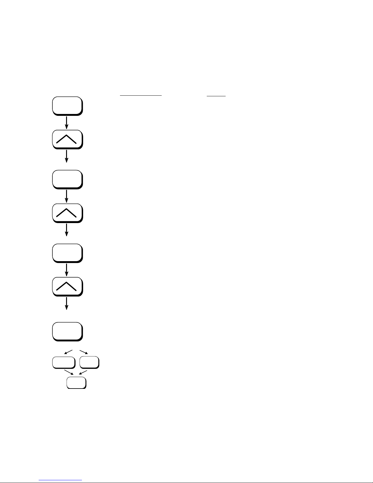
5.12. Print Direction Selection
This function selects the active print orientation (orientation of the
whole printout including graphics, etc. on the paper).
ON LINE
SAVE
SAVE
Panel display
[SOLID F90
HD ]
[Menu Level 1 ]
( ( (
[Paper Menu
[Page Length
( ( (
[Print Direct.
]
]
]
Notes
Turn the printer OFF LINE with this key.
Press one of the ARROW keys until
[Paper Menu ] is displayed.
Press one of the ARROW keys until
[Print Direct. ] is displayed.
[Print Direct. 0
]
Press the NEXT or PREVIOUS key until
the desired print direction is displayed.
( ( (
[Print Direct. 1
SAVE
]
The print direction 1 = landscape is
selected.
[Save as Setup? ]
In addition this new value can be saved
MENU
SAVE
as setup value (using the SAVE
key),
before the printer is turned ON LINE
ON LINE
Print direction assignment: Print direction 0 = Portrait (upright
again.
format)
Print direction 1 = Landscape (horizontal format)
Print direction 2 = Portrait upside down
Print direction 3 = Landscape upside down
________________________________________________________________________________________________
MICROPLEX Operator’s Manual SOLID F90 HD Edition 1.0
Page 60

60 Panel Functions
_______________________________________________________________________________________________
5.13. Data Interface Configuration
This function is used to set the interface parameters.
ON LINE
SAVE
SAVE
SAVE
SAVE
MENU
ON LINE
SAVE
Panel display
[SOLID F90
HD ]
[Menu Level 1 ]
( ( (
[Configuration ]
[Interface ]
[SIA Timeout ]
[Digit3 0
( ( (
[Digit2 04
30 ]
0 ]
[Save as Setup? ]
Notes
Turn the printer OFF LINE with this key.
Press one of the ARROW keys until
[Configurat
ion ] is displayed.
The currently set value for he timeout is
displayed (here: 30 seconds).
Pressing one of the ARROW keys
changes the value of the current
ion (Digit 3 = left position, in this
posit
example: 0). Pressing the SAVE key
moves you to the next digit (the MENU
key moves you back, if need be).
The timeout (the waiting period for SIA
to switch to the next interface) is
increased to 40 seconds.
In addition this new value can be
saved as setup value (
using the SAVE
key), before the printer is turned ON
LINE again.
Note:
The printer uses SIA (Simultaneous Interface Administration) to check,
which interface is currently used for the transfer of print data.
________________________________________________________________________________________________
MICROPLEX Operator’s Manual SOLID F90 HD Edition 1.0
Page 61
Panel Functions 61
_______________________________________________________________________________________________
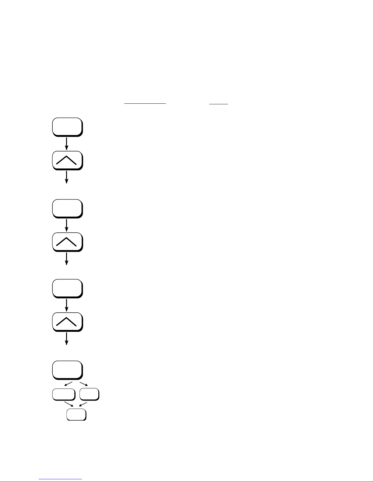
5.14. Emulation Selection
With this function you can change the active emulation.
ON LINE
SAVE
Panel display
[SOLID F90
HD ]
[Menu Level 1 ]
( ( (
[Configuration ]
[Interface]
( ( (
[Emulation ]
Notes
Turn the printer OFF LINE with this
key.
Press one of the ARROW keys until
[Configurat
ion ] is displayed.
Press one of the ARROW keys until
[Emulation ] is displayed.
SAVE
[SOLID Standard ]
Press one of the ARROW keys
until the desired emulation
( ( (
(e.g. HP PCL 5) is displ
ayed.
[HP PCL 5 ]
SAVE
The emulation HP PCL 5 is selected.
[Save as Setup? ]
MENU
SAVE
ON LINE
In addition this new value can be
saved as setup value (
using the
SAVE key), before the printer is
turned ON LINE again.
________________________________________________________________________________________________
MICROPLEX Operator’s Manual SOLID F90 HD Edition 1.0
Page 62

62 Panel Functions
_______________________________________________________________________________________________
Available emulations:
Standard:
MICROPLEX IDOL,
HP LaserJet (PCL 5),
Epson FX,
IBM Proprinter,
TIFF (CCITT group 4),
µPostscript
Optional:
Kyocera Prescribe,
Printronix IGP/PGL,
ZPL II (Zebra Programming Language),
Datamax (FGL),
Eltron EPL2,
Diablo 630,
AGFA Reno,
S3000 Lineprinter,
HPGL (7475A),
DEC LN03+,
Tally MT 6xx,
Bull MP6090,
IDS/IDS2,
QMS (Magnum) Code V,
ANSI Genicom,
XEROX XES,
HP DesignJet (HPGL-2),
LDC (Label Description Language),
Express
(More emulations on request)
Notice:
The brand names mentioned are registered trademarks of the
enterprises named above.
________________________________________________________________________________________________
MICROPLEX Operator’s Manual SOLID F90 HD Edition 1.0
Page 63
Panel Functions 63
_______________________________________________________________________________________________
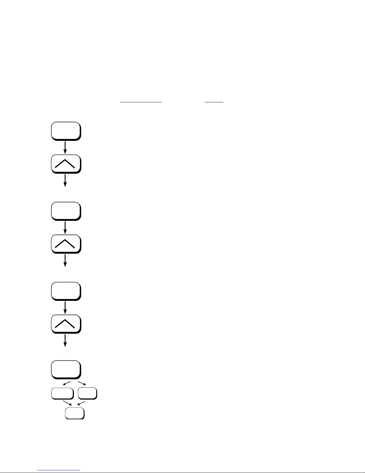
5.15. Display Language Selection
This function enables the user to determine the language for the
display messages, the status sheet and the font list.
ON LINE
SAVE
Panel display
[SOLID F90 HD ]
[Menu Level 1 ]
( ( (
[Configuration ]
[Interface ]
( ( (
[Language ]
Notes
Turn the printer OFF LINE with this
key.
Press one of the ARROW keys until
[Configurat
ion ] is displayed.
Press one of the ARROW keys until
[Language ] is display
ed.
SAVE
[German ]
Press one of the ARROW keys until
e.g. English)
( ( (
the desired language (
is displayed.
[English ]
SAVE
The display language English is
selected.
[Save as Setup? ]
MENU
ON LINE
SAVE
In addition this new value can be
saved as setup value (
using the
SAVE key), before the printer is
turned ON LINE again.
________________________________________________________________________________________________
MICROPLEX Operator’s Manual SOLID F90 HD Edition 1.0
Page 64

64 Panel Functions
_______________________________________________________________________________________________
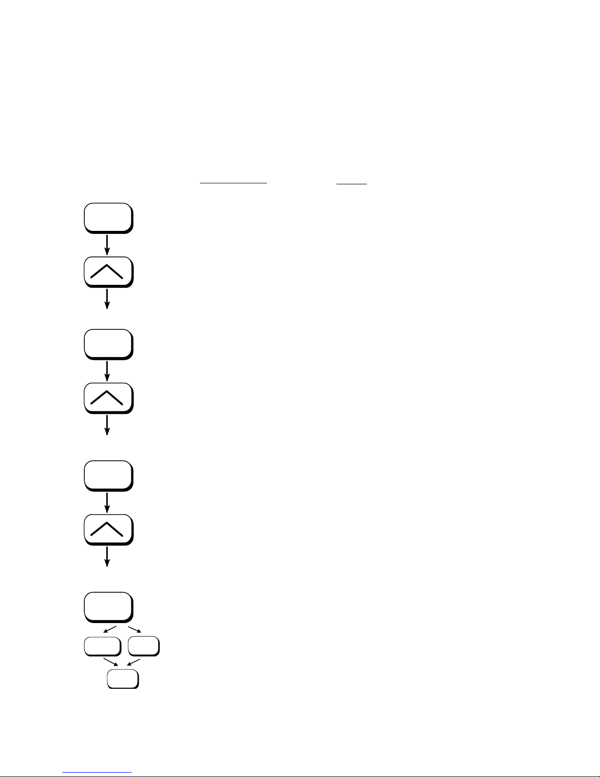
5.16. Transparent Code Adjustment
This function configures the transparent code. Using the transparent
code enables you to initiate the commands of the page description
language IDOL by
setting is 2625. These are the ASCII character codes (hexadecimal)
printable characters. The transparent code pre-
ON LINE
SAVE
SAVE
SAVE
for the characters
& % (ref. IDOL Programming Manual).
Panel display
[SOLID F90 HD ]
[Menu Level 1 ]
( ( (
[Configuration ]
[Interface ]
( ( (
[Transparent Code ]
[Digit4 2
( ( (
[Digit1 2626
625]
]
[Save as Setup? ]
Notes
Turn the printer OFF LINE with this key.
Press one of the ARROW keys until
[Configurat
ion ] is displayed.
Press one of the ARROW keys until
[Transparent Code ] is displ
The hexadecimal numbers for
preset.
Pressing one of the ARROW keys
ayed.
& % are
changes the value of the current digit
(Digit4 = left position, in this example: 2).
Pressing the SAVE key moves you to the
next digit (the MENU key moves you back).
2626 is selected as transparent code.
From now on use the characters
& &
before programming the IDOL commands.
MENU
________________________________________________________________________________________________
SAVE
ON LINE
MICROPLEX Operator’s Manual SOLID F90 HD Edition 1.0
In addition this new value can be saved as
setup value
(using the SAVE key), before
the printer is turned ON LINE again.
Page 65
Panel Functions 65
_______________________________________________________________________________________________
5.17. Selection of Memory Distribution (Input Buffer)
This function enables the user to choose the distribution of the
available RAM memory between input buffer and macro/download
memory.
ON LINE
SAVE
Panel display
[SOLID F90
HD ]
[Menu Level 1 ]
( ( (
[Configuration ]
[Interface ]
( ( (
[Input Buffer ]
Notes
Turn the printer OFF LINE with this key.
Press one of the ARROW keys until
[Configurat
ion ] is displayed.
Press one of the ARROW keys until
[Input Buffer ] is displayed.
SAVE
[32 kB ]
Press one of the ARROW keys until the
desired memory distribution is
ayed. The input buffer size is
displ
( ( (
specified in kilobyte (kB) or in percent
of the installed memory.
[100 kB ]
SAVE
100 kB is selected as input buffer.
[Save as Setup? ]
MENU
SAVE
In addition this new value can be
saved as setup value (using the SAVE
ON LINE
key), before the printer is turned ON
LINE again.
________________________________________________________________________________________________
MICROPLEX Operator’s Manual SOLID F90 HD Edition 1.0
Page 66

66 Panel Functions
_______________________________________________________________________________________________
5.18. Setting to Factory Default
This function back-outs all configurations to factory defaults.
ON LINE
SAVE
Panel display
[SOLID F90
HD ]
[Menu Level 1 ]
( ( (
[Configuration ]
[Interface ]
( ( (
Notes
Turn the printer OFF LINE with this
key.
Press one of the ARROW keys until
[Configurat
ion ] is displayed.
Press one of the ARROW keys until
[Factory Default ] is dis
played.
[Factory Default ]
SAVE
[Save as Setup? ]
Only if you press the SAVE key a
second time the configuration will be
ON LINE
SAVE
back-outed to factory defaults.
The printer is turned ON LINE
MENU
again.
________________________________________________________________________________________________
MICROPLEX Operator’s Manual SOLID F90 HD Edition 1.0
Page 67
Panel Functions 67
_______________________________________________________________________________________________
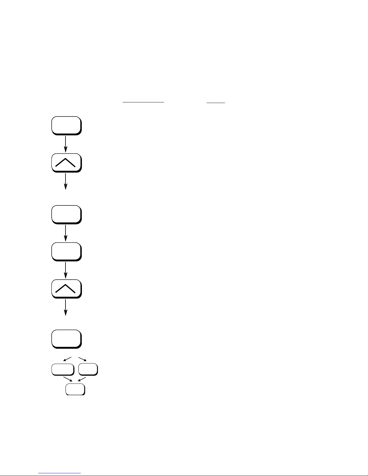
5.19. Font Selection
This function selects the active font. Select font number out of the list
of available fonts.
ON LINE
SAVE
SAVE
Panel display
[SOLID F90
HD ]
[Menu Level 1 ]
( ( (
[Page Menu ]
[Font Number ]
[Font 0600 ]
Notes
Turn the printer OFF LINE with this
key.
Press one of the ARROW keys until
[Page Menu ] is displayed.
Press one of the ARROW keys until
the desired font number (5507
( ( (
Langeoog e.g.) is displ
ayed.
[Font 5507 ]
SAVE
The font nu
mber 5507 is selected.
[Save as Setup? ]
In addition this new value can be
MENU
SAVE
saved as setup value (using the
SAVE key), before the printer is
ON LINE
________________________________________________________________________________________________
turned ON LINE again.
MICROPLEX Operator’s Manual SOLID F90 HD Edition 1.0
Page 68

68 Panel Functions
_______________________________________________________________________________________________
The SOLI
D F90 HD standard equipment contains the
following fonts:
Font no.
0600 10 12 Kurilen
0602 10
0610 12
1710 12
4508 P
4510 P 10 Helgoland
4714 P
5507 20 7 Langeoog
5508 16.6
5509 15
6610 10 10.1 Juist Monosp.
9210 P
9310 P
2000 P
9900 P
Font width Font height Font name
12 Kurilen
10.1
10.1 Kurilen
8.1 Helgol
14.4 Helgoland Bo
7.9
9.1
10.1
10.1 Tasmanien
SC
SC
Kurilen
Langeoog
Langeoog
Tasmanien
Tasmanien
Neuwerk
Italic
Italic
and
Italic
ld
Resumption
Explanations:
________________________________________________________________________________________________
Font width:
Character distance in CPI (Characters Per Inch).
P = proportional, (meaning that each character has an individual width).
Font height:
Font height from the lowest descender to the upper edge of the highest
character, measured in graphical points (1/72 inch).
SC = scalable.
of this standard font list see next page.
MICROPLEX Operator’s Manual SOLID F90 HD Edition 1.0
Page 69

Panel Functions 69
_______________________________________________________________________________________________
PCL 5 compatible
Font no.
0050 SC Plakatschrift
0590 SC
0591 SC
6600 SC
0699 SC Kurilen
1700 SC
1800 SC
1900
5500
5600 SC
5700 SC
5800
2100
2200 P
2300
9800
9500
9600
0060 SC Plakatschrift
9501
9601 P SC Neuwerk-II Condensed Bold Ital.
9801 P SC Neuwerk-II Condensed BoId
9901 P SC Neuwerk-II Condensed
0530
5100 P
5200 P
5300 P
7500 P
7700 P
7800
7900 P
9199 P
9299 P
9399 P
9499 P
Font width Font height Font name
OCR
/B
OCR
/A
Juist Mono
Kurilen
Kurilen Bo
SC Kurilen Bold Italic
SC Langeoog
Langeoog Bo
Langeoog
SC Langeoog Bold Italic
P
P SC Texel Bold Italic
P
P SC Neuwerk Bold Italic
P
P SC Neuwerk-II Condensed Italic
P
P
SC Texel
SC Texel
SC Neuwerk
SC Neuwerk
SC PiktoW
SC
SC Amrum Bo
SC Amrum
SC Antigu
SC Antigua Bold
SC Antigua
SC Antigua Bold
SC Tasmanien-II Bold
SC
SC Tasmanien-II It
SC Tasmanien-II
Amrum
Tasmanien-II
spaced
Italic
ld
ld
Italic
Bold
Italic
Italic
Bold
in
ld
Italic
a
Italic
Italic
Italic
alic
Bold
Notes:
Addit
depending upon the memory capacity.
You can use the panel function Printing the Font List (see section
5.2) to generate a list of all fonts installed to the printer.
________________________________________________________________________________________________
MICROPLEX Operator’s Manual SOLID F90 HD Edition 1.0
ional fonts can be selected from the font catalogue
Page 70

70 Panel Functions
_______________________________________________________________________________________________
5.20. Text Orientation Selection
This function selects the active text orientation.
ON LINE
SAVE
SAVE
Panel display
[SOLID F90
HD ]
[Menu Level 1 ]
( ( (
[Page Menu ]
[Font Number ]
( ( (
[Orientation ]
Notes
Turn the printer OFF LINE with this
key.
Press one of the ARROW keys until
[Page Menu ] is displayed.
Press one of the ARROW keys until
[Orientatio
n ] is displayed.
[Orientation 0 ]
Press one of the ARROW keys until
( ( (
the desired orientation is displ
ayed.
[Orientation 1 ]
The orientation 1 = landscape is
SAVE
selected.
[Save as Setup? ]
MENU
SAVE
In addition this new value can be
saved as setup value (
using the
SAVE key), before the printer is
ON LINE
turned ON LINE again.
Text orientation assignment: Orientation 0 = Portrait (upright format)
Orientation 1 = Landscape (horizo
ntal format)
Orientation 2 = Portrait upside down
Orientation 3 = Landscape upside down
________________________________________________________________________________________________
MICROPLEX Operator’s Manual SOLID F90 HD Edition 1.0
Page 71
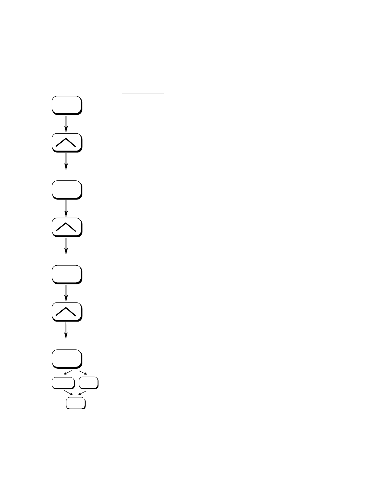
Panel Functions 71
_______________________________________________________________________________________________
5.21. Symbol Code Selection
This function selects the active symbol code.
ON LINE
SAVE
Panel display
[SOLID F90
HD ] [Menu
Level 1 ]
( ( (
[Page Menu ]
[Font Number ]
( ( (
[Symbol Code ]
Notes
Turn the printer OFF LINE with this
key.
Press one of the ARROW keys until
[Page Menu ] is displayed.
Press one of the ARROW keys until
[Symbol Co
de ] is displayed.
SAVE
[902, IBM PC-II ]
Press one of the ARROW keys until
the desired symbol code is
( ( (
displ
ayed.
[901, IBM PC-I ]
SAVE
The symbol code 901, IBM PC-I is
selected.
MENU
SAVE
ON LINE
[Save as Setup? ]
In addition this new value can be
saved as setup value (
using the
SAVE key), before the printer is
turned ON LINE again.
________________________________________________________________________________________________
MICROPLEX Operator’s Manual SOLID F90 HD Edition 1.0
Page 72

72 Panel Functions
_______________________________________________________________________________________________
5.22. Configuration of Text Margins
This function sets text margins. Margins are expressed in dots at
the concerning edge of the paper.
ON LINE
SAVE
Panel display
[SOLID F90
HD ]
[Menu Level 1 ]
( ( (
[Page Menu ]
[Font Number ]
( ( (
Notes
Turn the printer OFF LINE with this
key.
Press one of the ARROW keys until
[Page Menu ] is displayed.
Press one of the ARROW keys until
[Margin ] is displ
ayed.
[Margin ]
SAVE
[Left ]
Press one of the ARROW keys until
( ( (
the desired margin is displayed.
[from Right ]
SAVE
[Digit4 0
089]
Pressing one of the ARROW keys
changes the value of the current digit
eft position, in this
( ( (
(Digit 4 = l
example: 0). Pressing the SAVE key
moves you to the next digit (the
[Digit1 0087
SAVE
[Save as Setup? ]
ON LINE
SAVE
MENU
________________________________________________________________________________________________
]
MENU key moves you back).
The right margin is changed into 87
dot.
In addition this new value can be
saved as setup value (
using the SAVE
key), before the printer is turned ON
LINE again.
MICROPLEX Operator’s Manual SOLID F90 HD Edition 1.0
Page 73

Panel Functions 73
_______________________________________________________________________________________________
5.23. Image Shifting to the X-Direction
This function shifts the print image in relation to the paper to the
X-direction (crosswise the print direction). Because the paper feed
is always centered to the middle in the SOLID F90 HD, the image
shifting might be necessary when using e.g. special paper
formats to shift the X-coordinate zero to the left paper edge.
Panel display
Notes
ON LINE
SAVE
SAVE
SAVE
MENU
ON LINE
SAVE
[SOLID F90 HD ]
[Menu Level 1
( ( (
[Engine
]
[Resolution
( ( (
[Image X-Pos.
[Image X-Pos.
( ( (
]
]
]
xxx ]
[Image X-Pos. 160
[Save as Setup? ]
]
Turn the printer OFF LINE with this key.
Press one of the ARROW keys until
[Engine ] is displ
ayed.
Press one of the ARROW keys until
[Image X-Pos.] is displ
ayed.
The panel function Image Shifting to the
X-Direction is selected.
xxx = currently set value.
(Default value =128).
Operating one of the ARROW ke
ys the
value for the image shift can be altered.
Values from 0 up to 254 are settable,
so a max. image shifting of appr. ±1 ¼
Inch (approx. ±32 mm) can be reached.
Now the new image X-Position is saved
In addition this new value can be saved
as setup value (using the SAVE
key),
before the printer is turned ON LINE
again.
________________________________________________________________________________________________
MICROPLEX Operator’s Manual SOLID F90 HD Edition 1.0
Page 74
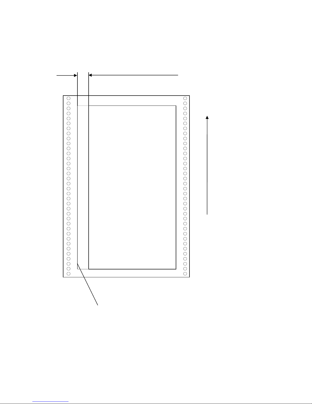
74 Panel Functions
_______________________________________________________________________________________________
Example for shifting the image to the X-direction:
Image shifting to the X-direction
Printout after the image
shifting to the X-direction.
In this example the value of
the Image X-Position was
increased (UP key).
Feed
direction
(print
direction)
Previous position of the
printout margin (prior to
the image shifting)
________________________________________________________________________________________________
MICROPLEX Operator’s Manual SOLID F90 HD Edition 1.0
Page 75
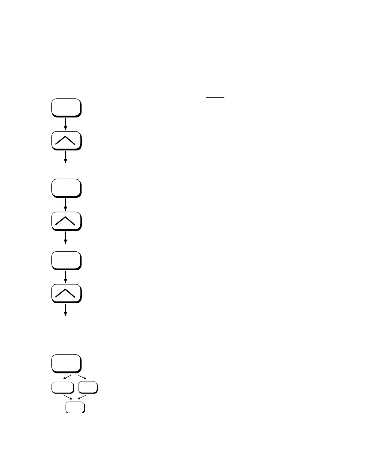
Panel Functions 75
_______________________________________________________________________________________________
5.24. Image Shifting to the Y-Direction
This function shifts the print image in relation to the paper to the
Y-direction (print direction).
ON LINE
SAVE
SAVE
Panel display
[SOLID F90
HD ]
[Menu Level 1 ]
( ( (
[Engine ]
[Resolution ]
( ( (
[Image Y-Pos. ]
Notes
Turn the printer OFF LINE with this
key.
Press one of the ARROW keys until
[Engine ] is displayed.
Press one of the ARROW keys until
[Image Y-Pos.] is displ
ayed.
The panel function Image Shifting to
the Y-Direction is selected.
[Image Y-Pos. yyy ]
yyy = currently set value.
(Default value = 128).
Operating t
he ARROW keys the
image can be shifted relative to the
paper. Values from 0 up to 254 are
settable, so a max. image shifting of
( ( (
approx. ± 1 ¼ Inch (approx. ± 32
mm) can be reached.
[Image Y-Pos. 190 ]
SAVE
MENU
ON LINE
[Save as Setup? ]
SAVE
Now the new image Y-Position is
saved.
In addition this new value can be
saved as setup value (
using the SAVE
key), before the printer is turned ON
LINE again.
________________________________________________________________________________________________
MICROPLEX Operator’s Manual SOLID F90 HD Edition 1.0
Page 76
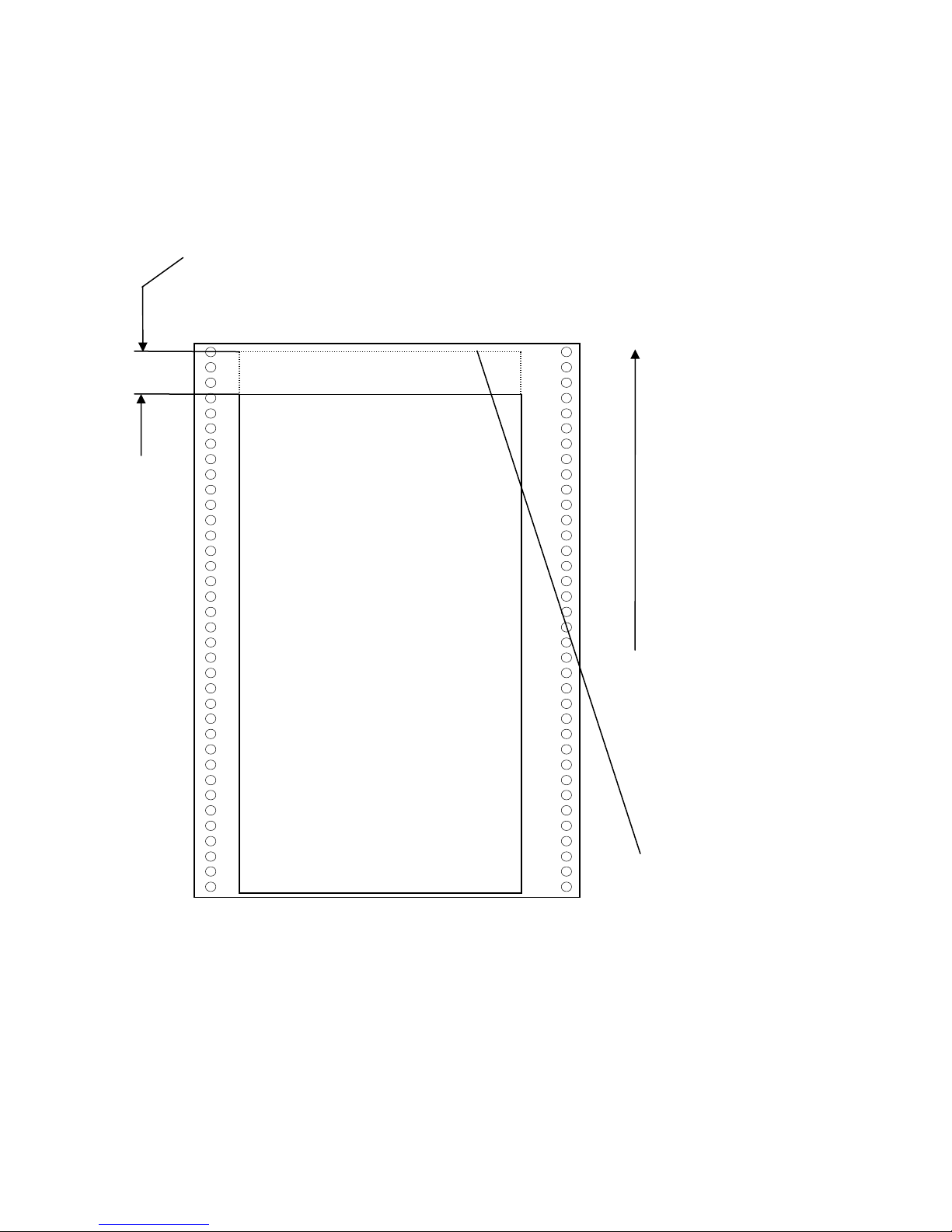
76 Panel Functions
_______________________________________________________________________________________________
Example for shifting the image to the Y-direction:
Image shifting to the Y-direction
Printout after the image
shifting to the Y-direction.
In this example the value of the
Image Y-Position was increased
(UP key).
Feed
direction
(print
direction)
________________________________________________________________________________________________
MICROPLEX Operator’s Manual SOLID F90 HD Edition 1.0
Previous position of the
printout margin (prior to
the image shifting)
Page 77
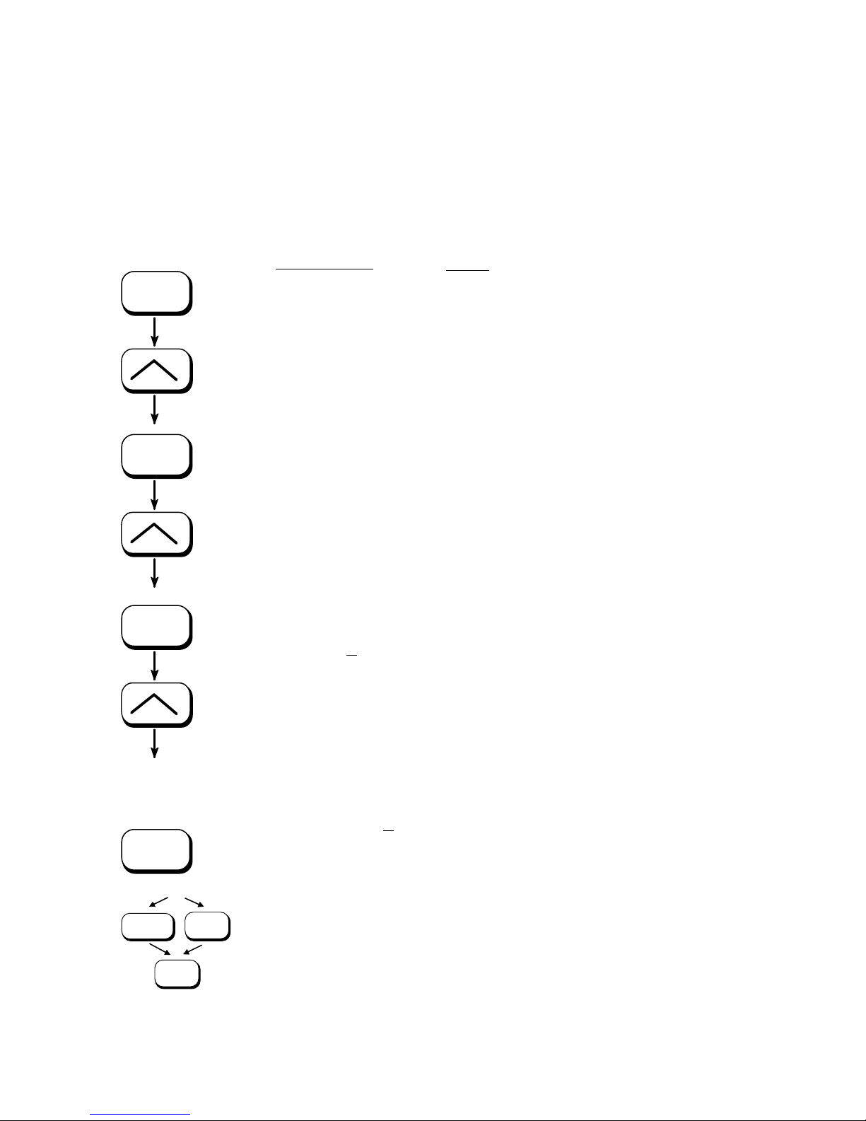
Panel Functions 77
_______________________________________________________________________________________________
5.25. Lines per Inch Setting (Line Spacing)
This function sets the number of lines per inch. This setting is effective
only in case of using the printer as a line printer.
With a small number of lines per inch, line spacing will be relatively
large. (Ref. IDOL Programming Manual).
ON LINE
SAVE
SAVE
Panel display
[
SOLID F90
HD ]
[Menu Level 1 ]
( ( (
[Page Menu
[Font Number
( ( (
[Line Spacing
[Digit4 0
( ( (
]
]
]
06.5 ]
Notes
Turn the printer OFF LINE with this key.
Press one of the ARROW keys until
[Page Menu ] is displayed.
Press one of the ARROW keys until
[Line Spacing ] is displayed.
6.5 lpi = currently set value.
lines per inch).
(
Pressing one of the ARROW keys changes the
value of the current digit (Digit 4 = left
position, in this example: 0). Pressing the
SAVE key moves you to the next digit (the
MENU key moves you back).
[Digit1 010.0
SAVE
[Save as Setup? ]
MENU
________________________________________________________________________________________________
SAVE
ON LINE
MICROPLEX Operator’s Manual SOLID F90 HD Edition 1.0
]
The number of lines per inch was increased
to 10 lpi.
In addition this new value can be saved as
setup value
(using the SAVE key), before the
printer is turned ON LINE again.
Page 78

78 Panel Functions
_______________________________________________________________________________________________
5.26. Number of Characters per Inch Setting (Character Spacing)
This function sets the number of characters per inch. This setting is
effective only in case of using a line printer emulation.
With a small number of characters per inch, character spacing will be
relatively large. (Ref. IDOL Programming Manual).
ON LINE
SAVE
SAVE
Panel display
[
SOLID F90
HD ]
[Menu Level 1 ]
( ( (
[Page Menu
[Font Number
( ( (
]
]
[Char. Spacing
[Digit4 0
( ( (
13.3 ]
]
Notes
Turn the printer OFF LINE with this key.
Press one of the ARROW keys until
[Page Menu ] is displayed.
Press one of the ARROW keys until
[Char. Spacing ] is displayed.
13.3 cpi = currently set value.
characters per inch).
(
Pressing one of the ARROW keys changes the
value of the current digit (Digit 4 = left
position, in this example: 0). Pressing the
SAVE key moves you to the next digit (the
MENU key moves you back).
[Digit1 012.0
SAVE
[Save as Setup? ]
MENU
________________________________________________________________________________________________
SAVE
ON LINE
MICROPLEX Operator’s Manual SOLID F90 HD Edition 1.0
]
The number of characters per inch
was reduced to 12 cpi.
In addition this new value can be saved as
setup value
(using the SAVE key), before the
printer is turned ON LINE again.
Page 79
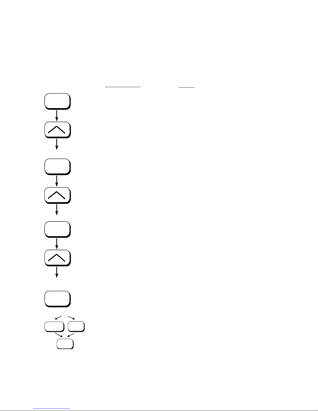
Panel Functions 79
_______________________________________________________________________________________________
5.27. Print Density Setting
Using this function the density of the printed characters can be
changed.
ON LINE
SAVE
SAVE
Panel display
[
SOLID F90
HD ]
[Menu Level 1 ]
( ( (
[Engine ]
[Resolution ]
( ( (
[Print Density ]
[Print Density 96 ]
Notes
Turn the printer OFF LINE with this
key.
Press one of the ARROW keys until
[Engine ] is displ
ayed.
Press one of the ARROW keys until
[Print Density ] is displayed.
96 = currently set value. (Default
value = 88).
[Print Density 104 ]
SAVE
[Save as Setup? ]
MENU
________________________________________________________________________________________________
SAVE
ON LINE
MICROPLEX Operator’s Manual SOLID F90 HD Edition 1.0
( ( (
Press one of the ARROW keys to
change the density.
Values from 0 up to 152 are settable.
The print density is increased, the
print image gets darker.
Now the new value is saved.
In addition this new value can be
saved as setup value (
using the SAVE
key), before the printer is turned ON
LINE again.
Page 80

80 Panel Functions
_______________________________________________________________________________________________
5.28. Configuration of Network Parameters (IP Address, e.g.)
The functions of the submenu Network are used to set the
parameters for connecting the printer to a network (Ethernet).
Setting the IP address manually:
ON LINE
SAVE
SAVE
Panel display
[SOLID F90 ]
[Menu Level 1 ]
( ( (
[Network
[Timeout
]
]
( ( (
[IP Assign ]
]
[Off
( ( (
[Manual
]
Notes
Turn the printer OFF LINE with this key.
Press one of the ARROW keys until
[Network ] is displayed.
Press the SAVE key to select the
Network menu.
Press one of the ARROW keys until
[IP Assign ] is displayed
.
Press the SAVE key to select the
IP Assing m
enu.
The current setting value is
displayed.
Press one of the ARROW keys until
[Manual ] is displayed.
SAVE
SAVE
[IP Address
92.168.002.002 ]
[1
]
Press the SAVE key to set the
IP address manually.
Pressing one of the ARROW keys
changes the value of the current digit
t, in this example: 1).
( ( (
(left digit firs
Pressing the SAVE key moves you to
the next position (the MENU key moves
[192.168.010.123
]
you back, if need be).
SAVE
[Saved !
]
The new IP address is saved as setup
value.
ON LINE
The printer is turned ON LINE again.
________________________________________________________________________________________________
MICROPLEX Operator’s Manual SOLID F90 HD Edition 1.0
Page 81

Panel Functions 81
_______________________________________________________________________________________________
Notes:
)
If your network is using DHCP
assigned (select the item
DHCP from the network submenu
, an address can be automatically
IP Assign).
The parameters
Subnet Mask and Gateway are configured in
the same way as described above. Please select the concerning
panel functions for this (compare section 5.7 Menu Structure).
Select the subitem
Off from the network menu to switch off the
network access.
)
a centralized address management.
________________________________________________________________________________________________
MICROPLEX Operator’s Manual SOLID F90 HD Edition 1.0
Dynamic Host Configuration Protocol: offers among other things
Page 82

82 Panel Functions
_______________________________________________________________________________________________
Duplex/Speed Setting
This panel function is located in the network menu
(submenu Duplex/Speed Setting).
The factory default value is Autonegotiation.
Autonegotiation means that devices on the network agree a
transmission mode, which each unit is able to handle, before
data transmission starts. By this the printer automatically
adjusts itself to maximize link performance.
Hint:
Autonegotiation is the recommended setting!
If you set the Duplex/Speed parameters manually, you may
experience problems. Wrong settings can slow down the
speed of the link (worst case: communication does not occur).
Explanations:
Auto-Negotiation
A Ethernet procedure that allows devices at either end of a
link segment to advertise and negotiate modes of operation
such as the speed of the link (100 Mbit/s or 10 Mbit/s) and
half- or full-duplex operation.
Half duplex
A device can either receive or send data at a given time.
________________________________________________________________________________________________
MICROPLEX Operator’s Manual SOLID F90 HD Edition 1.0
Full duplex
Capability of a device for sending and receiving data at the
same time. In the case of full duplex, collision detection is
deactivated. A full duplex capable device is able to buffer
data packets.
Page 83

Printer Cleaning 83
_______________________________________________________________________________________________
6. Printer Cleaning
By a regular and conscientious performance of the following
operations, the printer is guaranteed to always work at an
optimum reliability.
After the printing of about 20,000 pages A4 (print density 5 %;
!
compare chapter 10 Specifications) the components listed in this
chapter should be cleaned.
Please note:
The printer is provided with a drum counter.
Although this counter only records the revolutions of the drum,
the meter readings can be used to calculate values for the
“number of pages”. For every conversion you have to know the
page length of the printjob and to consider the following:
One digit of the counter corresponds to a page length of
14.8 inch, because this is the circumference of the drum.
Example: If 20,000 pages A4 portrait Two-Up have been printed
the number shown by the counter is approx. 7,900.
- Use a neutral detergent or water on a lintfree cloth to
remove dust or grease from the cover.
- Do not use detergents or any other devices or tools not
mentioned in this manual to avoid damages and
unnecessary costs of repairs.
- Please be especially careful to avoid damaging
mechanical or electronic modules.
Turn off the SOLID F90 HD printer and pull the power plug.
M
ake sure, the printer has been switched off for at least
15 minutes before you start cleaning.
________________________________________________________________________________________________
MICROPLEX Operator’s Manual SOLID F90 HD Edition 1.0
Page 84
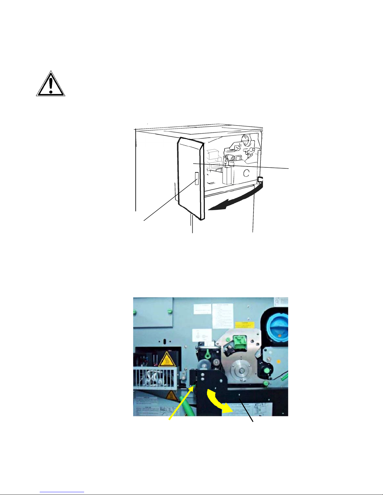
84 Printer Cleaning
_______________________________________________________________________________________________
6.1. Cleaning the Elements behind the Front Cover
Turn off the SOLID F90 HD printer and pull the powe
1.
plug. Make sure, the printer has been switched off for at
least 15 minutes before you start cleaning the device.
2. Open the front cover of the printer.
Handhold
3. Using an anti-static service vacuum cleaner, clean up
toner, paper dust or other particles which may have
accumulated.
r
Front
cover
4. Push down the
open lever of the waste toner recovery unit
and open the unit.
Open lever (green)
________________________________________________________________________________________________
Waste toner recovery unit
MICROPLEX Operator’s Manual SOLID F90 HD Edition 1.0
Page 85
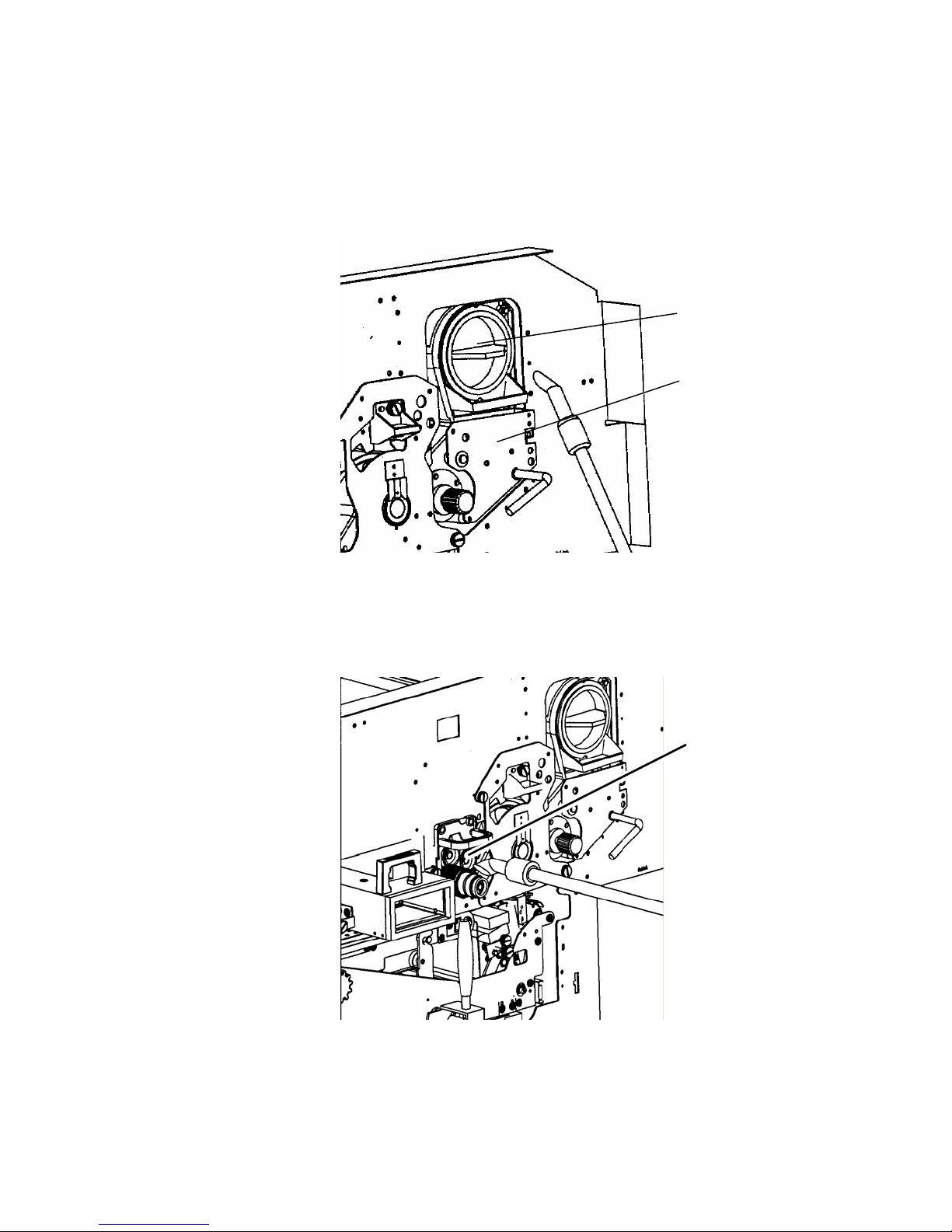
Printer Cleaning 85
e
t
_______________________________________________________________________________________________
5. Using an anti-static service vacuum cleaner, pick up any dirt
on the developer unit or toner cartridge.
Toner cartridg
Developer uni
6. Clean the drum cleaning unit and the elements around it in
the same way.
Drum cleaning
unit
________________________________________________________________________________________________
MICROPLEX Operator’s Manual SOLID F90 HD Edition 1.0
Page 86
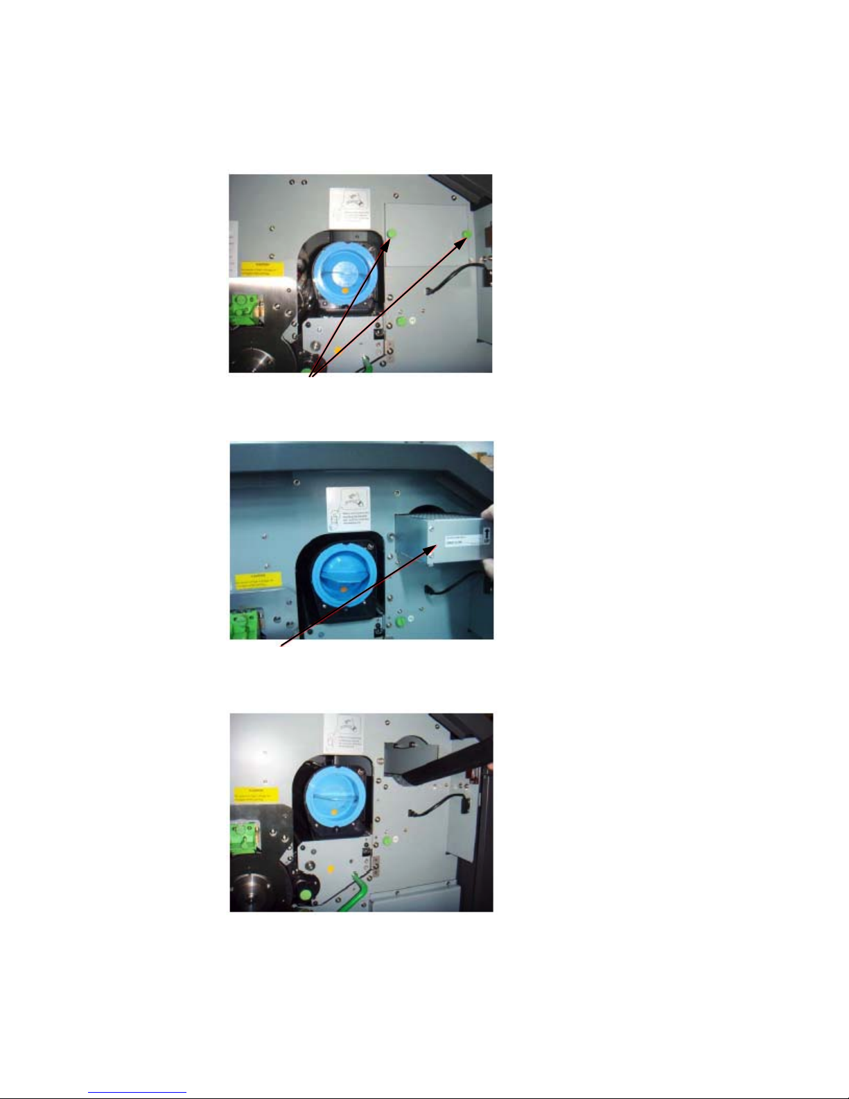
86 Printer Cleaning
_______________________________________________________________________________________________
7. Loosen the knurled screws (see figure below) and then remove the
dust filter cover.
Knurled screws
8. Pull out the dust filter.
Dust filter
9. Use an anti-static service vacuum cleaner to clean the dust filter area.
10. Insert a new dust filter and reassemble the cover using the two
urled screws.
n
k
________________________________________________________________________________________________
MICROPLEX Operator’s Manual SOLID F90 HD Edition 1.0
Page 87
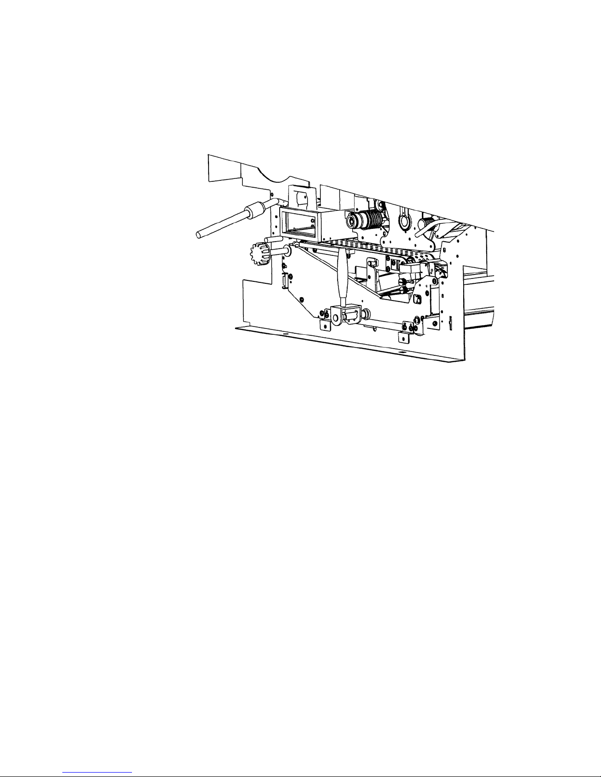
Printer Cleaning 87
_______________________________________________________________________________________________
11. Also vacuum the fuser unit and the area around it.
12. Close the waste toner unit.
Make sure the bar has engaged.
!
13. Close the printer’s front cover.
________________________________________________________________________________________________
MICROPLEX Operator’s Manual SOLID F90 HD Edition 1.0
Page 88
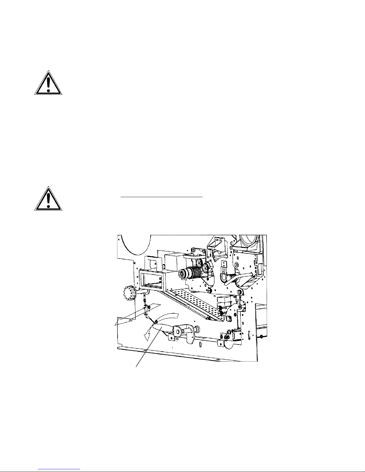
88 Printer Cleaning
_______________________________________________________________________________________________
6.2. Cleaning the Transport Unit
Turn off the SOLID F90 HD printer and pull the power
1.
plug. Make sure, the printer has been switched off for at
least 15 minutes before you start cleaning the device.
2. Open the front cover of the printer.
3. Open the waste toner unit (compare previous section).
4. Press down the green lever of the transport unit. The
transport path is set down by that.
5. Press down the lever while pulling the transport unit
towards you to avoid damag
until it stops.
ing the printer. Pull the unit
Green lever
________________________________________________________________________________________________
MICROPLEX Operator’s Manual SOLID F90 HD Edition 1.0
Page 89
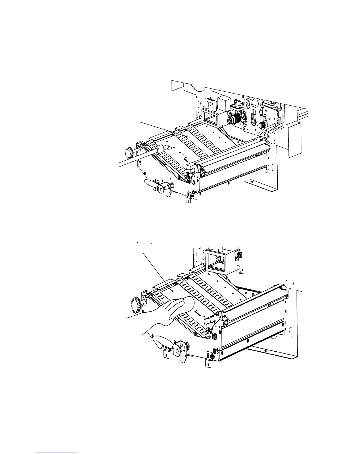
Printer Cleaning 89
_______________________________________________________________________________________________
6. Using an anti-static service vacuum cleaner, clean up
toner, paper dust or other particles which may have
accumulated.
Transport unit
7. Wipe off the dirt on the transport surface using a
wet paper towel.
Transportpath
________________________________________________________________________________________________
MICROPLEX Operator’s Manual SOLID F90 HD Edition 1.0
Page 90
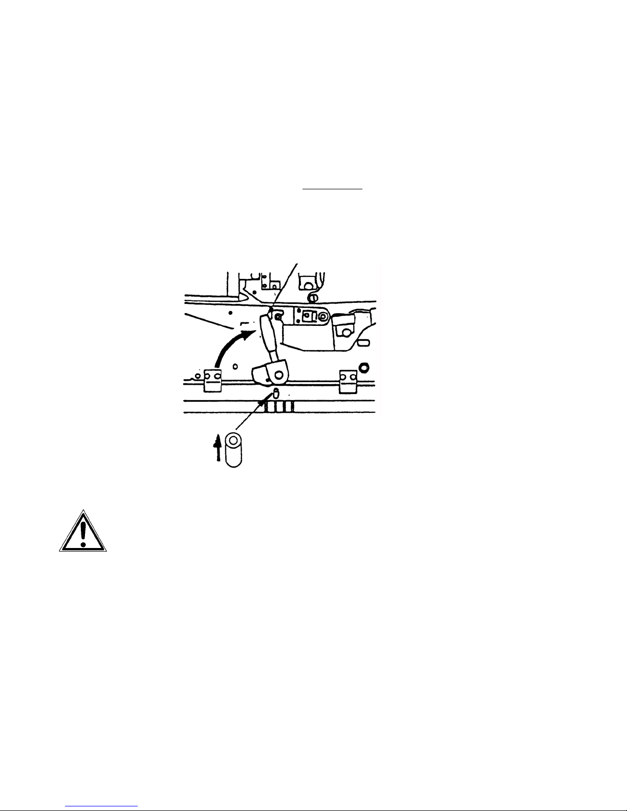
90 Printer Cleaning
_______________________________________________________________________________________________
8. Replace the transport unit. The green lever has to
be pressed down for this process. Slide the
!
transport unit into the printer until it stops w
pressing down the lever (resilience at the end).
Tip up the green lever of the transport
unit to its "up" position.
Pay attention to the second bar
located under the green lever - it also has to click into
place (second bar up).
of the transport unit
hile
Second bar up
Green lever and second bar up h
into place to avoid damaging the printer.
Green lever
ave to be clicked
9. Close the waste toner recovery unit.
Make sure the bars have engaged.
!
10. Close the printer’s front cover.
________________________________________________________________________________________________
MICROPLEX Operator’s Manual SOLID F90 HD Edition 1.0
Page 91
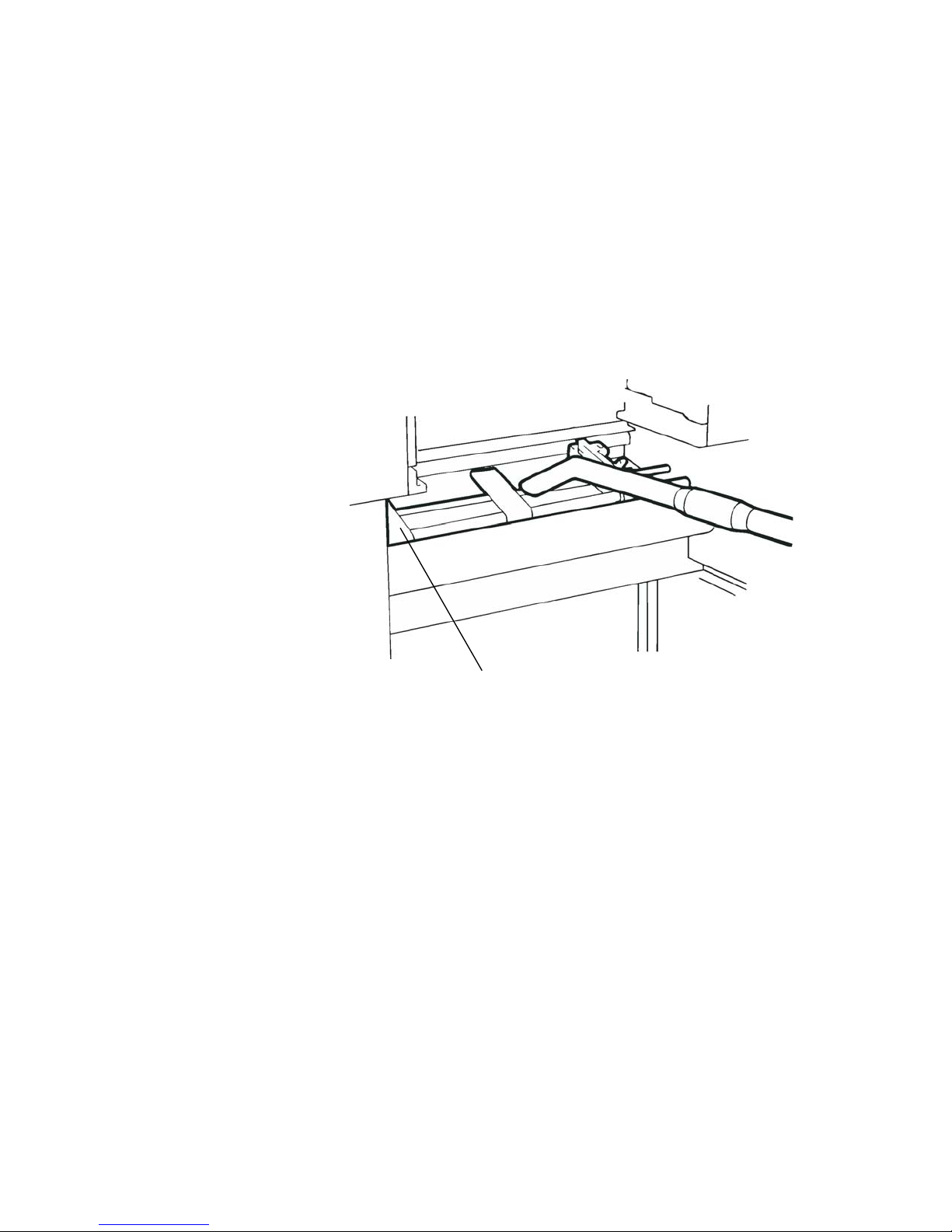
Printer Cleaning 91
_______________________________________________________________________________________________
6.3. Cleaning the Paper Feed Unit
Turn off the SOLID F90 HD printer and pull the power plug.
1.
2. Remove the paper.
3. Absorb paper dust, sprayed toner etc. from the tractor
and the area around it using an anti-static service vacuum
cleaner.
4. Load the paper.
Tractor
________________________________________________________________________________________________
MICROPLEX Operator’s Manual SOLID F90 HD Edition 1.0
Page 92
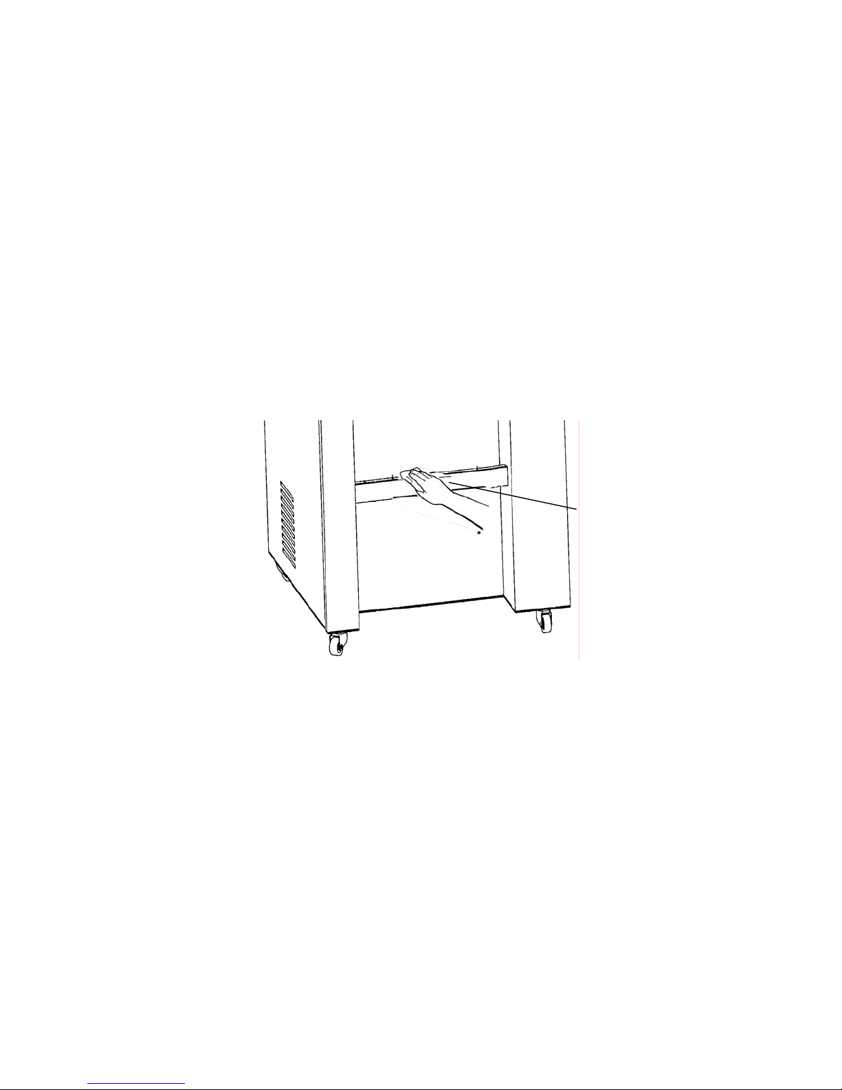
92 Printer Cleaning
_______________________________________________________________________________________________
6.4. Cleaning the Paper Near End Sensor
After 300,000 pages A4 have been printed, the Paper Near
End Sensor (PNES) and the area around it should be cleaned
!
carefully.
Turn off the SOLID F90 HD printer and pull the power plug.
1.
2. Clean the PNES and the area around using a wet paper
towel.
Gear of the
paper near end
sensor
________________________________________________________________________________________________
MICROPLEX Operator’s Manual SOLID F90 HD Edition 1.0
Page 93
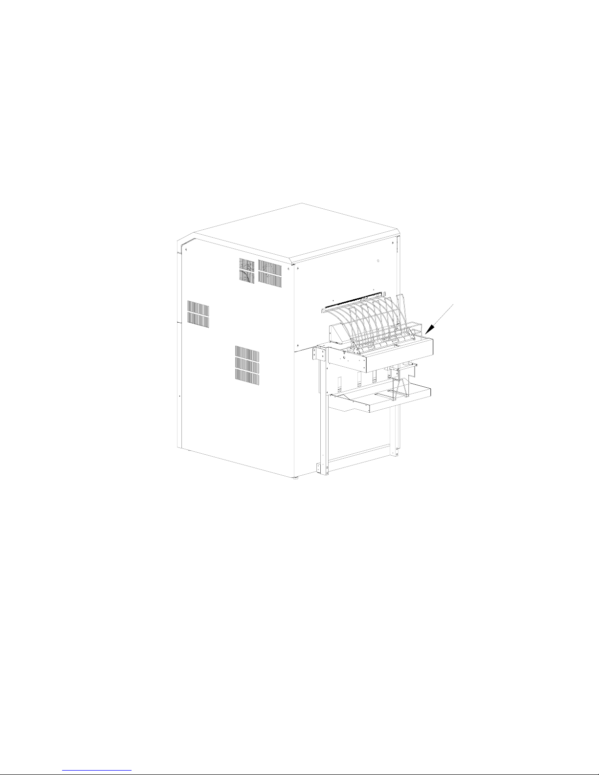
Printer Cleaning 93
_______________________________________________________________________________________________
6.5. Cleaning the Power Stacker
After 200,000 pages A4 have been printed, the power
stacker and the area around it should be cleaned using a
!
vacuum cleaner.
Stacker
________________________________________________________________________________________________
MICROPLEX Operator’s Manual SOLID F90 HD Edition 1.0
Page 94

94 Printer Cleaning
_______________________________________________________________________________________________
________________________________________________________________________________________________
MICROPLEX Operator’s Manual SOLID F90 HD Edition 1.0
Page 95

Operator Maintenance 95
_______________________________________________________________________________________________
7. Operator Maintenance
In order to run the printer always on its highest quality level, it is
necessary to perform regularly cleaning operations. In addition
special components have to be replaced if the occasion arises.
These operations can be performed by a MICROPLEX trained
operator. A untrained person is not allowed to perform these
!
operations.
The maintenance cycles given in this chapter are valid for printing
with a print density of 5 % (if no other values are specified; see also
chapter 10 Specifications).
Please note: The printer is provided with a drum counter.
The drum counter’s meter readings can be used to calculate values
for the “number of pages” (compare chapter 6 Printer cleaning;
If, for example 20,000 pages A4 portrait Two-Up have been printed
the number shown by the counter is approx. 7,900).
Further maintenance operations have to be done by the service
engineer (in accordance with the hints given in the Service Manual).
!
7.1. Charger Cleaning
The operations described in this section have to be performed after
!
!
the printing of every 50,000 pages A4 (portrait Two-Up).
Turn off the printer and pull the power plug before start working at
the chargers.
To clean the chargers the following tools are avail
a blower brush, a special wire cleaning tool and a emery block for
the cleaning of the main charger's grid.
Please clean the chargers especially careful to
tearing the tightened wires. Improper replacement of the chargers
into the printer may damage the photoreceptor drum.
able:
avoid loosening or
________________________________________________________________________________________________
MICROPLEX Operator’s Manual SOLID F90 HD Edition 1.0
Page 96
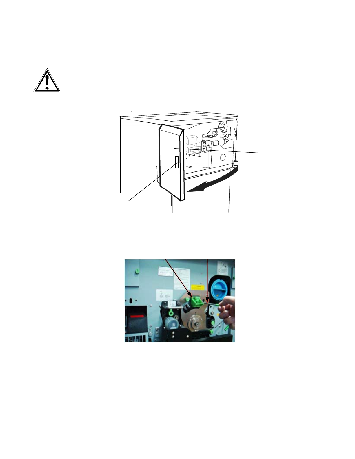
96 Operator Maintenance
_______________________________________________________________________________________________
7.1.1. Main Charger Cleaning
Turn off the printer and pull the power plug before start working
at the chargers.
1. Open the front cover of the printer.
Front
cover
Handhold
2. Pull out the cleaning rod horizontally and then insert it back
several times for cleaning
Main charger Cleaning rod
3. Loosen the knurled screw of
the wire of the main charger.
the main charger and pull o
t the
u
charger.
________________________________________________________________________________________________
MICROPLEX Operator’s Manual SOLID F90 HD Edition 1.0
Page 97
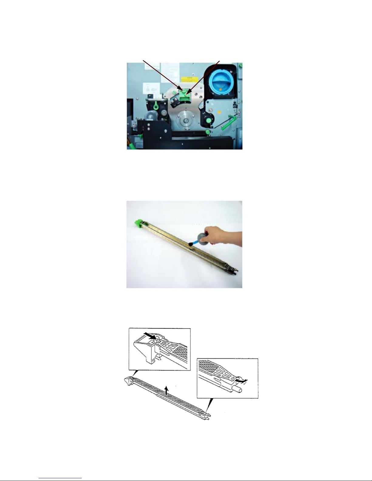
Operator Maintenance 97
_______________________________________________________________________________________________
Knurled screw Main charger
4. Place the charger on a clean and level worktop.
5. Clean the housing of the main charger using the blower brush.
6. Remove the grid from the main charger. For this please push
________________________________________________________________________________________________
MICROPLEX Operator’s Manual SOLID F90 HD Edition 1.0
on the tab and remove the grid.
Page 98
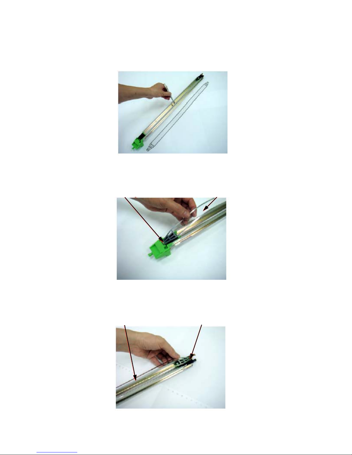
98 Operator Maintenance
_______________________________________________________________________________________________
7. Use the wire cleaning tool to clean the charger’s wire.
After this process the wire should be completely smooth.
8. Reassemble the grid to the main charger. First you have to
mount the grid to the plastic pin.
Plastic-Pin Grid
9. Hold the plastic end of the main charger while mounting the
end of the grid to the metal
free
Grid Metal pin
pin.
________________________________________________________________________________________________
MICROPLEX Operator’s Manual SOLID F90 HD Edition 1.0
Page 99

Operator Maintenance 99
_______________________________________________________________________________________________
10. Replace the main charger in its original position (compare
picture in step 2) and tighten the knurled screw.
11. Close the printer’s front cover.
________________________________________________________________________________________________
MICROPLEX Operator’s Manual SOLID F90 HD Edition 1.0
Page 100
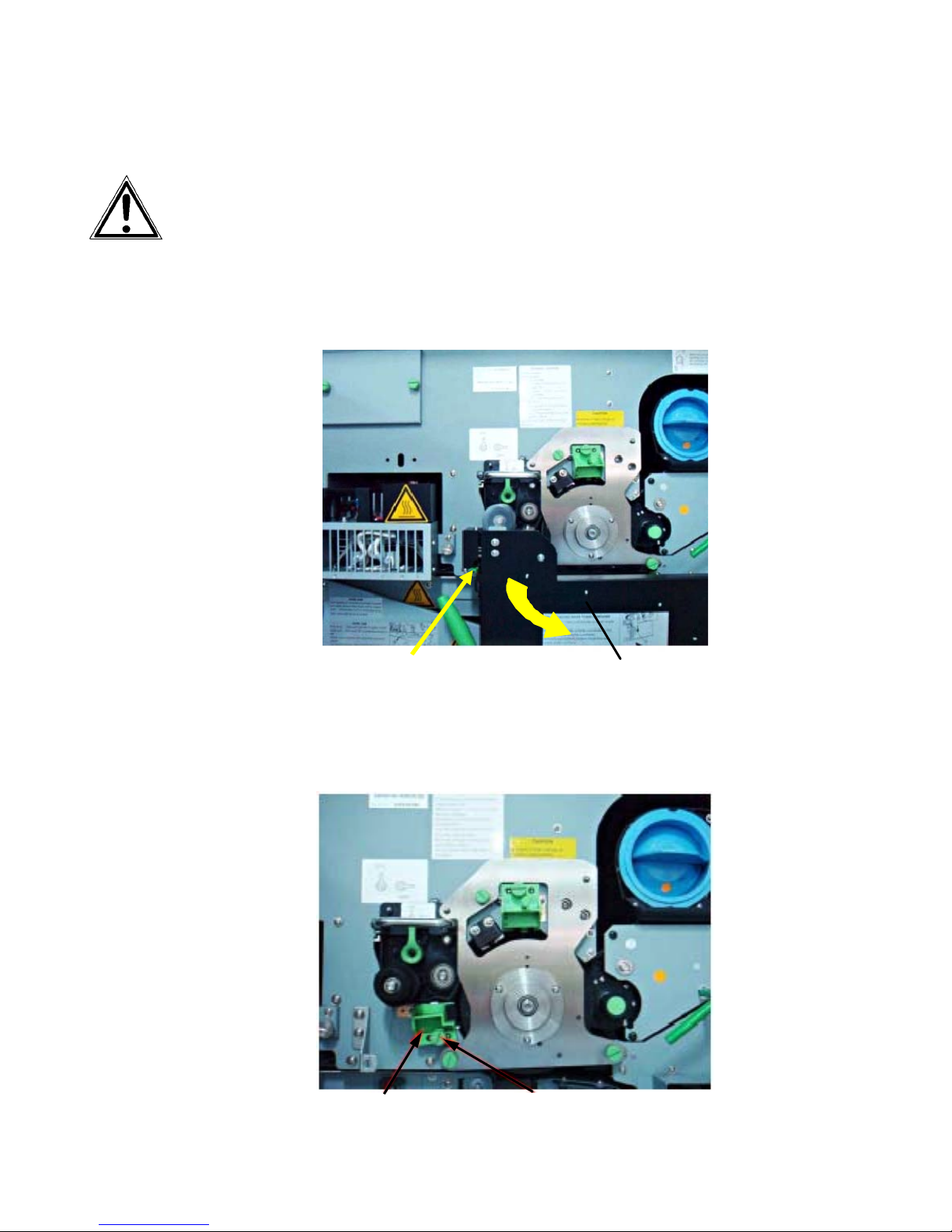
100 Operator Maintenance
_______________________________________________________________________________________________
7.1.2. Pre-Charger Cleaning
Turn off the printer and pull the power plug before start working at
the chargers.
1. Open the front cover of the printer.
2. Press down the open lever to open the waste toner recovery unit.
Open lever (green)
Waste toner recovery unit
3. Loosen the knurled screw of the pre-charger and pull out the
charger.
Pre-charger Knurled screw
________________________________________________________________________________________________
MICROPLEX Operator’s Manual SOLID F90 HD Edition 1.0
 Loading...