


USER MANUAL
Fanfold Printer
Multi-Purpose Printer

Acknowledgements
EPSON is a Trademark of Seiko Epson Corporation.
IBM is a Trademark of International Business Machines Corporation. Proprinter is a
Trademark of International Business Machines Corporation.
A Publication of Microplex
100 Northfield Rd
Bedford, OH 44146
USA
November 2015
Number: 5112 991 20523
http:\\www.microplex-
usa.com
Great care has been taken to ensure that the information in this handbook is accurate and complete. However,
should any errors or omissions be discovered or should any user wish to make suggestions for improving this
handbook, please feel encouraged to send us the relevant details.
The contents of this manual are subject to change without notice.
Copyright © by Microplex.
All rights strictly reserved. Reproduction or issue to third parties in any form is not permitted without written
authorization from the publisher.

I
Safty Regulations
The printer PP 404 (Fanfold Printer) and PP 405 (Multi-purpose Printer) fulfils the safety
regulations according to EN 60950-1, UL 60950-1 and CAN/CSA 22.2/No. 60950-1 for Information
Technology Equipment.
The mains cable must be connected to a ground protected wall-socket. The indicated voltage of
the printer needs to agree with the local voltage.
The power plug must be easily accessible at any time so that it can be disconnected immediately
in case of danger or for maintenance purposes.. Comme le câble de secteur sert de dipositif
d'arrêt-urgence, sa connexion à l'imprimante doit être tout le temps accessible.
Before installing the printer, check the surrounding conditions in which the printer will be placed
(see next page, Operating Environment and chapter 1).
During a thunderstorm you should never attempt to connect or disconnect any data transfer
cables.
The power supply should only be opened and checked by authorized personnel. Repairs and
maintenance beyond the descriptions of chapter 3 Maintenance may only be attempted by
authorized personnel as well. Repairs done inappropriately may cause damage and severe danger
for the user.
There are warning symbols to draw the user's attention to possible injuries:
This symbol is visible when the top cover has been opened. It indicates that the print
head is extremely hot after long periods of printing.
This symbol is located after the front cover. It indicates the possibility to go through
the both holes into the mechanical part of the printer - danger of hurt!

I
Safty Regulations
Electromagnetic Compatibility
We certify that the equipment at issue,
Printer PP 405 (Multi-purpose Printer))
Corresponds to the law regulations ruling electromagnetic compatibility of appliances
(2004/108/EC) and, therefore, fulfils the requirements for conformity marking with the CE-sign.
In order to ensure the adherence to the limit values in accordance with that test standards for
breakdown sending (EN 55022, class B) and noise immunity
(EN 55024), in principle shielded interface cables are to be used.
This equipment has been tested and found to comply with the limits for a Class B digital device,
pursuant to Part 15 of the FCC rules. These limits are designed to provide reasonable protection
against harmful interference in a residential installation. This equipment generates, uses, and can
radiate radio frequency energy and, if not installed and used in accordance with the instruction
manual, may cause interference to radio communications.
However, there is no guarantee that interference will not occur in a particular installation. If this
equipment does cause harmful interference to radio or television reception, it can be determined
by turning the equipment off and on. The user is encouraged to try to correct the interference
by one or more of the following measures:
Reorient or relocate the receiving antenna.
Increase the separation between the equipment and receiver.
Connect the equipment to an outlet on a circuit different from the circuit to
receiver is connected.
which the
Consult the dealer or an experienced radio/TV technician for help.
Shielded interface cables should be used with this unit to ensure compliance with Class B limits.
Changes and modifications not explicitly allowed by the equipment's manufacturer could void
the user's authority to operate the equipment.
Changes et modifications pas expressément approuvés par le producteur peuvent dévaluer
l'autorité d'opérer l'équipement.
.

III
Content
1. Getting Started.......................................................................................... 1-1
1.1. Unpacking the Fanfold Printer ............................................................... 1-1
1.2. Unpacking the Multi-purpose Printer .................................................... 1-3
1.2.1 A First Look at the Multi-purpose Printer ................................................. 1-4
1.3. Site Considerations ................................................................................ 1-5
1.4. Transport Lock ....................................................................................... 1-6
1.5. Installing the Personality Module (only Multi-purpose Printer) ............. 1-7
1.6. The Power Supply .................................................................................. 1-8
1.7. Power ON/OFF Switch ........................................................................... 1-9
1.8. Installing the Ribbon Cassette .............................................................. 1-10
1.9. Tractor ................................................................................................. 1-15
1.10. Manual Front Insertion Guide .............................................................. 1-18
1.11. Output Stacker (only Multi-purpose Printer) ....................................... 1-19
1.12. Selection of Operator Panel Language ................................................. 1-20
1.13. Paper Source Selection ........................................................................ 1-21
1.14. Print Test ............................................................................................. 1-22
1.15. To start a print test: ............................................................................. 1-23
1.16.
1.17. Emulation Select .................................................................................. 1-38
2. Printer Operation ...................................................................................... 2-1
2.1 The control panel................................................................................... 2-1
2.2 Function Keys ........................................................................................ 2-2
2.3 Menu-Mode .......................................................................................... 2-9
Installation of Personality Module (PM).
Connection to a Computer Parallel or Serial or USB ......................................... 1-25
HTTP Web Server (PSi Printer WebPanel) ......................................................... 1-29
PNS Display Current Settings ............................................................................ 1-31
PNS Page Basic Settings .................................................................................... 1-32
PNS Page Network Administration ................................................................... 1-34
PNS Configuration Logical Printer ..................................................................... 1-35
PNS Page Printer Actions .................................................................................. 1-36
2.2.1 Short Description of Keys ....................................................................... 2-2
2.2.2 Detail Description of Keys ...................................................................... 2-4
To Activate the Menu: ....................................................................... 2-9
To Confirm Selection: ...................................................................... 2-10
How to Save Settings ....................................................................... 2-11
................................................ 1-25

III
Quick Settings .................................................................................. 2-11
...................................................................................................................... 2-11
3. Maintenance ............................................................................................. 3-1
3.1 Cleaning ................................................................................................. 3-1
3.2 Cleaning Procedure ................................................................................ 3-3
3.3 User Replaceable Parts .......................................................................... 3-4
3.4 Replacement of the Platen ..................................................................... 3-7
4. Troubleshooting and Diagnostics ............................................................... 4-9
4.1 Power-related Problems ...................................................................... 4-10
Error Messages ............................................................................................. 4-10
4.1.1 Errors during Self-test .......................................................................... 4-10
4.1.2 Errors during Printing ........................................................................... 4-12
4.1.3 Technical Errors.................................................................................... 4-14
4.1.4 No Printout ........................................................................................... 4-15
4.3.1 Operation-related Problems ............................................................ 4-16
4.1.5 Print-related Problems ......................................................................... 4-17
4.1.6 Ribbon or Carriage-related Problems ................................................... 4-12
4.1.7 Print Tests ............................................................................................ 4-12
4.2 Diagrams of Errors ............................................................................... 4-13
4.2.1 PAPER JAM TRF (fanfold paper jam) ................................................ 4-13
4.2.2 PAPER JAM ASF (only Multi-purpose Printer) or MANUAL ............. 4-14
4.2.3
4.2.4 PRINT FAINT OR OF POOR QUALITY ................................................ 4-16
5. ASF-Cassettes (only for Multi Purpose Printer) .......................................... 5-1
5.1 Automatic Sheet Feeder Cassettes (ASF) ............................................... 5-1
5.1.1 Checking the Delivery Consignment .................................................. 5-1
5.1.2 Prepare the ASF Cassettes ................................................................. 5-2
5.1.3 Installing the ASF Cassettes ............................................................... 5-3
5.1.4 Removing the ASF Cassette ............................................................... 5-5
5.1.5 lnsert Paper ....................................................................................... 5-6
5.2 Replacement of the ASF Pick-up Rollers ................................................. 5-8
5.2.1 To Remove the ASF Pick-up Rollers (3) .............................................. 5-8
5.2.2 To Install the Pick-up Rollers ............................................................. 5-9
6. Technical Data ........................................................................................... 6-1
Appendix A Configuration of the Printer ............................................................ 1
A.1 What is Configuring................................................................................... 1
A.2 Standard Configuration ............................................................................. 3
A.3 Explanation of the printouts on the previous pages .................................. 5
NO PRINTOUT I NO PRINTING
.......................................................... 4-15

III
A.4 Explanation of the Individual Menu Items ................................................. 6
Appendix B System Interface Description ............................................................ 1
B.1 Serial Interface RS-232C ............................................................................ 2
B.2 Parallel Interface ....................................................................................... 3
B.3 Additional Information .............................................................................. 4
B.4 USB Interface ............................................................................................ 5
Appendix C Character Set Tables .................................................................... 6
C.1 Code Page ISO 8859-1 ............................................................................... 6
C.2 Code Page ISO 8859-15 ............................................................................. 2
C.3 Code Page ISO 8859-5 ............................................................................... 3
C.4 Code Page ISO 8859-9 ............................................................................... 4
C.5 Code Page IBM All Character Set .............................................................. 5
C.6 Code Page IBM Set 1 ................................................................................. 6
C.7 National Version IBM Set 1 ...................................................................... 7
C.8 Code Page IBM Set 2 ................................................................................. 8
C.9 National Version IBM Set 2 ...................................................................... 9
IBM Code Pages .................................................................................................. 10
C.10 IBM Code Page 437 USA, ASCII, and Graphics ....................................... 11
C.11 IBM Code Page 850 Greek (437) and ISO 8859-1.................................... 12
C.12 IBM Code Page 858 Latin 1 with € Sign ................................................. 13
C.13 IBM Code Page 860 Portugal .................................................................. 14
C.14 IBM Code Page 863 Canada, French ....................................................... 15
C.15 IBM Code Page 865 Norway ................................................................... 16
C.16 IBM Code Page 857 Turkey ..................................................................... 17
C.17 EPSON Extended Graphics Code Page..................................................... 18
C.18 National Version EPSON Extended graphics Code Page ......................... 19
C.19 EPSON Italic Code Page........................................................................... 20
C.20 National Version EPSON Italic Code Page (part 1) .................................. 21
C.21 National Version EPSON Italic Code Page (part 2) .................................. 22
Code Pages for the Eastern European Countries (EE) ........................................... 23
C.22 Code Page 437 Greek .............................................................................. 23
C.23 Code Page 851 Greek .............................................................................. 24
C.24 Code Page 928 Greek .............................................................................. 25
C.25 Code Page 855 Cyril ................................................................................ 26
C.26 Code Page 866 Russia ........................................................................... 27
C.27 Code Page 869 Greek ............................................................................. 28
C.28 Code Page 852 Multilingual Latin 2 ....................................................... 29
C.29 Code Page KAMENICKY ........................................................................... 30

III
C.30 Code Page ISO LATIN 2 ............................................................................ 31
C.31 Code Page MAZOVIA ............................................................................... 32
C.32 Code Page 437 HUN ................................................................................ 33
C.33 Code Page 852 SEE .................................................................................. 34
C.34 Code Page 866 LAT ................................................................................. 35
C.35 Code Page WIN LAT2 .............................................................................. 36
Code Pages for the Eastern European Countries (EE2) ......................................... 37
C.36 Code Page 771 Lithuanian and Russian ................................................. 37
C.37 Code Page 773 Latin 7 (Baltic old standard) .......................................... 38
C.38 Code Page 774 Lithuanian = IBM 1118 .................................................. 39
C.39 Code Page 775 (Baltic Rim) .................................................................... 40
C.40 Code Page BALTIC RIM ............................................................................ 41
C.41 Code Page 1251 Win Cyrillic ................................................................... 42
C.42 Code Page 1125 / 866 Ukrainian ............................................................ 43
C.43 Code Page OCR-A .................................................................................... 44
Appendix D IBM ProPrinter Quick Reference ........................................................ 1
Appendix E EPSON LQ 2550 and ESC/P2 Quick Reference .................................. 1
Appendix F Bar Code Quick Reference ........................................................... 1
Appendix G Print Samples of Resident Fonts ......................................................... 1

III
Preface
Preface
About this Manual
This manual is covering the two printers
Fanfold Printer
Multi-purpose Printer
The operation and functionality are nearly the same. In most illustrations, the Multi-purpose
Printer is used. In case there are differences in the handling you will find the note:
Fanfold Printer
or
Multi-purpose Printer
The Interface (Personality Module (PM)) is an integral part of the printer, and the type of PM
used determines the functionality of the printer especially regarding the user and system
interface.
This manual is divided into the following chapters:
1. Getting Started
2. This chapter covers the unpacking and setting-up of the printer and the installation of
the ribbon cassette. By the end of this chapter the printer should be fully functional and
tested in its primary form. It is not yet connected to the host computer system and no
options are mounted.
3. Operating the Printer
4. This chapter discusses in great detail the operation of the operator panel, menu
functions, and the general operation of the menu.

III
Preface
5. Maintenance
6. shows how to clean the printer and how to replace the platen and the print head.
7. Trouble Shooting and Diagnostics
8. Suggests how to identify and correct simple problems.
9. Automatic Sheet Feeder Cassettes (ASF) (only for Multi-purpose Printer) this chapter
shows how to handle the ASF Cassettes.
10. Technical Data
11. All technical details or data about the printer can be found here.
Appendix
A. Configuring the Printer
This chapter explains how to configure the printer so that it can communicate with the
corresponding system environment. Then this chapter thoroughly describes the printer's
operating controls. In the last part you will find explanations of individual menu items. At
The end of this chapter you will find the Menu tree.
B. Interface Description
This chapter gives hints about possibilities to connect the printer to the various computer
systems and explains particularities depending on the version of the operating system.
Additionally, cable connection is illustrated.
C. Character Set Table
All printer supported character sets are listed in this chapter.
D. Control Codes
Quick reference for IBM Proprinter and IBM Proprinter AGM (4207, 4208 XL 24) Emulation.
E. Control Codes
Quick reference for EPSON LQ 2550 / 1060 /ESC/P2 Emulation.

III
AGC
Automatic Gap Control
ASF
Automatic Sheet Feeder Cassette for cut sheets and form sets
EE
Eastern European
LCD
Liquid Crystal Display
LED
Light Emitting Diode
LQ
Letter Quality
MACRO
User defined group (1 bis 4) of stored parameter
NLQ
Near Letter Quality
PM
Interface (Personality Module)
A. Barcode Quick Reference
Quick reference for Bar Code programming.
B. Print Samples of Resident Fonts
Conventions Used in this Guide
The following conventions are used:
Bold: Headlines and important information.
Note: Contains special advice to facilitate handling.
Caution: Contains important information to prevent damage of the equipment.
[ENTER] Key functions are always depicted in brackets or you will find the symbol
of the key e.g.
Abbreviations and Acronyms
Preface
1-1
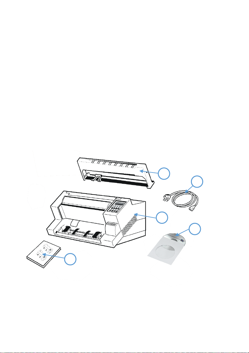
(1)
24-Needle Printer
(2) Ribbon cassette
(3)
Power cord
(4) Quick reference guide
(5)
CD-ROM
4
5 1 3
2
1. Getting Started
1.1. Unpacking the Fanfold Printer
Check each item against the check list detailed below. Contact your reseller immediately if any item
is missing or damaged.
The printer package should contain the following:
Caution: Do not connect to the mains until the main's voltage has been checked (see
paragraph 1.6 The Power Supply).
Note: Save all packing material and boxes for future transportation of the printer. The
printer drivers for Windows ® are available on the enclosed CD- ROM.

Getting Started
1-2
(1)
Printer
(2)
Ribbon Cassette
(3)
Top Cover
(4)
Tractor for Continuous Paper
(5)
Paper Supports
(6)
Front Cover
(7)
Control Panel
(8)
Tear off edge
(9)
Serial / Parallel / USB Input
(10)
Power Cord Socket
(11)
Power Switch
1
11
8 9 10
5
3
2
7
4
6
1.1.1 A First Look at the Fanfold Printer
Before installing the printer, spend some time familiarizing yourself with the printer.

Getting Started
1-3
(1)
Output Stacker
(2) Ribbon Cassette
(3)
Printer
(4) Quick Reference Guide
(5)
Personality Module (PM) (sep.)
(6) Power Cord
(7)
CD-ROM
1 5 2
6
3
4
7
1.2. Unpacking the Multi-purpose Printer
Check each item against the check list detailed below. Contact your reseller immediately if any
item is missing or damaged.
The printer package should contain the following:
A separate box contains the Personality Module (5)
Caution: Do not connect to the mains until the PM is installed and the main's voltage selection
has been checked. (See paragraph 1.5 and 1.6).
Note: Save all packing material and boxes for future transportation of the printer. The
printer drivers for Windows ® are available on the enclosed CD- ROM.

Getting Started
1-4
(1)
Printer
(2)
Ribbon Cassette
(2)
Top Cover
(4)
Tractor for Continuous Paper
(3)
Paper Supports
(6)
Front Cover
(4)
Control Panel
(8)
Tear off edge
(5)
Serial / Parallel / USB Input
(10)
Power Cord Socket
(6)
Power Switch
(11)
Personality Module (PM)
11
12
10 9 8
6 7 5
4
3 2 8
1
1.2.1 A First Look at the Multi-purpose Printer
Before installing the printer, spend some time familiarizing yourself with the printer.

Getting Started
1-5
1.3. Site Considerations
Environment Conditions
Install the printer in an area away from any heat source, air conditioner or strong draught.
Avoid installing the printer in a dusty or humid environment.
Work Location
Place the printer on the stand or a flat, solid level area such as a desk.
Slots and openings in the printer's housing are provided for ventilation; always ensure that
these openings are not obstructed.
Always place the printer with its front edge slightly off the edge of the table when
processing fanfold paper.
Also ensure that the cables at the rear of the printer do not interfere with the output paper
path.
Power Requirements
No special wiring is required. A typical office wall outlet is sufficient.
Do not plug in other equipment besides the printer such as coffee machines, copy machines
or air conditioners into the same wall outlet.

Getting Started
1-6
1
8
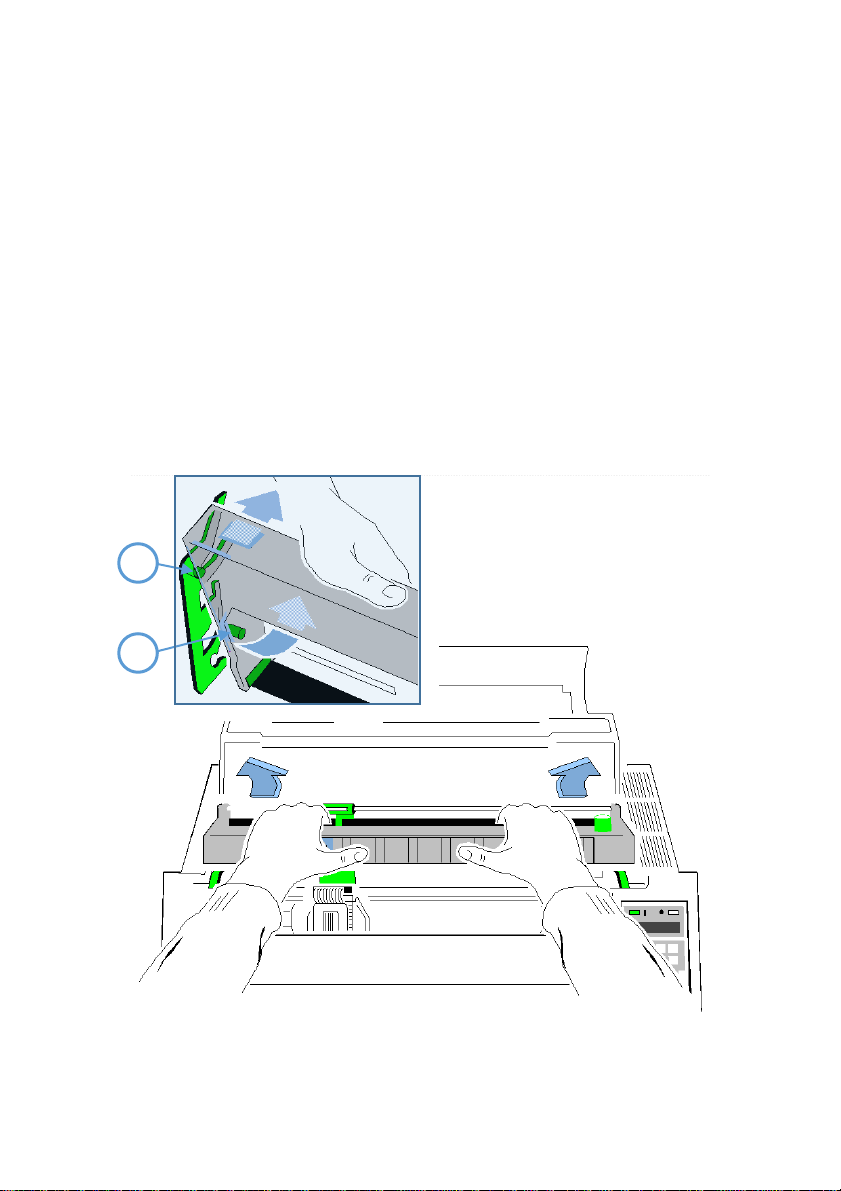
1.4. Transport Lock
You will find a red shipping tab under the top cover (1).
Grasp the top cover (1) on the left and right, lift it and remove the transport locking clip (2)
from the print head drive belt.
Re-packing Information
Note: Save all packing material and boxes for future transportation of the printer. To ensure
maximum protection when transporting the printer, always
Remove any installed paper handling option.
Remove the output stacker and the mains cable.
Remove the ribbon cassette.
Reposition the transport locking clip.
Pack the printer in its original packing material and ship in its original box.

Getting Started
1-7
1
2
1.5. Installing the Personality Module (only Multi-purpose Printer)
The printer functions only in combination with an installed interface module, called a
Personality Module (PM).
The illustration below shows the standard PM with a serial, parallel, and USB interface.
Note To avoid damage due to electrostatic discharge, do not touch the pins or components
of the PM.
Never attempt to install or remove a PM while the printer is switched ON
1.
Switch-off the printer
2.
Remove the PM (1) from its packaging.
3.
Insert the Personality Module (1) with the component side upwards until the
connector fully engages. Hand tightens the two locks screws (2).

Getting Started
1-8
2
1
1.6. The Power Supply
Mains Voltage
In general, the main's voltage selection is determined at factory sites.
Make sure that the specified voltage on the label (1) corresponds to your main's voltage:
The 230 V setting applies to the range of 180 to 264 V alternating current.
Note: Since an incorrect voltage selection can seriously damage the printer, please pay
special attention to the following.
Connect the printer to the mains using the power cord (2). First connect the cable to the
power cord socket and then to the mains.
Note: As the power cord serves as a safety cut off, its connection to the printer must be
accessible any time.

Getting Started
1-9
1
1.7. Power ON/OFF Switch
The power ON/OFF switch (1) turns the printer's power supply ON or OFF.
After switched ON the printer an internal self-test which checks the electronics, the print head
carriage movement and the interface will be performed.
At first the yellow LED on the Operator Panel is lighting up and the display shows TEST.....0.1
(bootstrap). In the next step the yellow LED will be dark, the green LED lights up and the display
shows TEST....FW..0101234 (version of the firmware).
If the message INSTALL RIBBON is shown, follow the steps in paragraph 1.8 installing the
Ribbon Cassette.
If the message INSTALL RIBBON is shown, follow the steps in paragraph 1.8 installing the
Ribbon Cassette.
After inserting the ribbon press to continue. When the internal test has been completed
successfully the display shows READY 1 ELQ or BUSY 1 ELQ in case data has already been
transmitted.
Note: If the display shows anything different, please refer to chapter 4 Troubleshooting and
Diagnostics.

Getting Started
1-10
1.8. Installing the Ribbon Cassette
It is recommended to use only original ribbon puts out by our company. Using other ribbons will
void your warranty.
Caution: Never manually move the print head fully to the right-hand stop (you could change
the way of the paper output).
Note: If the printer is busy (message BUSY 1 ELQ) always press before opening the
top cover.
1.
Switch the printer ON at the power switch; Power LED is lit and waits for the message
READY 1 ELQ or INSTALL RIBBON.
2.
If the printer is busy (message BUSY 1 ELQ) press .
3.
Lift the top cover to gain access to the ribbon cassette mountings. The print head will
move to the correct position, aligned with the cut out in the paper guide plate to facilitate
the installation of the ribbon cassette.
4.
Remove any excess slack by turning the green knob on the ribbon cassette clockwise. Move
the ribbon feed guide to the position indicated on the plastic cover of the cassette
Note: See illustrations on the next pages.

Getting Started
1-11
1
3
2
Insert the Ribbon Cassette with the ribbon at the bottom. Position the upper mounting pin (1) on
the green guide on both sides. Slide the cassette downward. In this position, the ribbon feed
guide touches the green plastic clip.

Getting Started
1-12
5. Move the cassette toward you until you hear a click on both sides. Swing the ribbon
underneath the print head for the final click. The audible clicks indicate that the mounting
pins have engaged properly.
klick!

Getting Started
1-13
Note: When installed correctly the ribbon cassette has a sloping position.
6. Move the print head back and forth to settle the ribbon in the correct position.
7. If necessary, remove excess ribbon slack by turning the green knob clockwise.
8. Close the top cover and press [START/STOP] .
Getting Started
1-14
1
2
1.8.1. Replacing the Ribbon Cassette
Caution: The print head may be very hot immediately after printing!
Close the top cover and switch the printer ON. Lift the top cover after the display shows
the message READY 1 ELQ to gain access to the ribbon cassette mountings. The print
head will move to the correct position, aligned with the cut out in the paper guide plate
to facilitate the installation of the ribbon cassette.
Now swing the lower part of the ribbon to the back.
In this way the mounting pins loosen from the lower position.
Then press the upper part of the ribbon to the back. The upper mounting pins get free
and the ribbon can be taken out.
Note: To install a new ribbon cassette please see 1.8 installing the Ribbon Cassette
(See pages before).

Getting Started
1-15
1
1.9. Tractor
Inserting Fanfold Paper for the First Time
Ensure that the printer is placed in the depression on the top of the stand (option). If the printer is
used without a stand, align the printer with the front edge of the table. The cables at the back of
the printer should be tucked into the cable clips in order not to block the paper path.
Note: (only for Fanfold Printer)
Note: (only for Multi-purpose Printer) hold the front of the manual insertion guide (4) on both
sides, pull upwards against the resistance and remove by pulling forward.

Getting Started
1-16
3 3 1
for both Printer:
Pull the green tractor lock levers (2) toward you to release the tractors.
Lock the left tractor (1) at the new position by pressing the green tractor levers (2)
backward.
Roughly adjust the right tractor to the paper width, and space out the paper supports (3)
evenly.

Getting Started
1-17
1
2
1. Open the tractor covers (1) and insert the paper.
2. Close the tractor covers.
3. Tighten the upper edge of the fanfold paper by slightly pushing the right tractor to the
right. Make sure not to stress the paper too much.
4. Lock the tractors by pushing back the green lock lever again.
Note: The pins of the tractor must be centered in the transport punches of the paper Reapply the
manual front insertion guide.

Getting Started
1-18
1
2
1.10. Manual Front Insertion Guide
Multi-Purpose Printer
Move the left-hand paper guide into the position indicated by ⓪ on the insertion
guide. In this setting the margin has the smallest value possible.
Adjust the right-hand paper guide (2) to the width of the paper to be used.
Note: If continuous form paper is in print position on the platen and has not been torn off, it will
be moved forward and TEAR OFF PAPER will be displayed.

Getting Started
1-19
1
2
1.11. Output Stacker (only Multi-purpose Printer)
Install the output stacker (1) into one of the two rails in the top cover (2). The meaning of the
two Positions:
for paper with 80 g/m² or thicker use the steeper position (left picture);
for thinner papers use the less inclined position (right picture).
Check, if the manual sheet insertion is installed.

Getting Started
1-20
1.
Power on printer
2. LO C AL
3. MAC RO S ELE CT
4.
[] -- []
INSTALLATIO N
5.
[]
INTERF AC E
6.
[] -- []
LANG UAG E
7.
[]
ENG LIS H
8.
[]
DE UTS CH
9.
[]
DE UTS CH
10
[]
S PR ACHE
11.
[]
INSTALLATION
12
[]
MENÜ SICHERN
13
[]
SICHERT
14
MENÜ SICHERT
BEREIT 1 ELQ
1.12. Selection of Operator Panel Language
The printer control panel and LCD display menu is used for the next steps. It is possible to change
the language in the printer menu from English to French or German. The following example
shows how to change from English to German:
KEY DISPLAY
Note: In chapter 2 Printer operating you will find a description of the function keys.

Getting Started
1-21
4.
[] -- []
[]
MANUAL
[]
5.
[]
[]
MANUAL
6.
READY
1 ELQ
1.13. Paper Source Selection
The basic selections for PAPER SOURCE are:
TRACTOR (Default, indicated by ’)
MANUAL
Select 'MANUAL' as paper source on the operator panel
The following diagram shows which keys to press and what is displayed on the operator panel.
KEY DISPLAY
1.
Switch the printer ON and wait for the message READY 4 ELQ
2.
3.
Note: Starting now the top row keys function as arrow keys.
STOP
TRACTOR
After that LOAD MANUAL is displayed. Insert a single sheet evenly. After a short delay,
the printer draws in the sheet..

Getting Started
1-22
1.14. Print Test
There are three test printouts available.
PRINT TEST 1 shows a pattern of all printable characters. Use this to check if the printer
operates correctly.
PRINT TEST 2 produces a standard letter (ECMA-132) which can be used for
the printer's throughput.
PRINT TEST 3 lists all available fonts, contains the page count to identify the actual
number of printed pages, and gives information on technical releases which are intended
for service purposes.
The print tests are printed using the parameters set in the menu, e.g. fonts, pitch etc. Refer to
section "Menu Mode" for details.
ABCDEFGHIJKLMNOPQRSTUVWXYZabcdefghijklmnopqrstuvwxyz0123456789!§
§ABCDEFGHIJKLMNOPQRSTUVWXYZabcdefghijklmnopqrstuvwxyz0123456789!
!§ABCDEFGHIJKLMNOPQRSTUVWXYZabcdefghijklmnopqrstuvwxyz0123456789
9!§ABCDEFGHIJKLMNOPQRSTUVWXYZabcdefghijklmnopqrstuvwxyz012345678
89!§ABCDEFGHIJKLMNOPQRSTUVWXYZabcdefghijklmnopqrstuvwxyz01234567
789!§ABCDEFGHIJKLMNOPQRSTUVWXYZabcdefghijklmnopqrstuvwxyz0123456
6789!§ABCDEFGHIJKLMNOPQRSTUVWXYZabcdefghijklmnopqrstuvwxyz012345
56789!§ABCDEFGHIJKLMNOPQRSTUVWXYZabcdefghijklmnopqrstuvwxyz01234
456789!§ABCDEFGHIJKLMNOPQRSTUVWXYZabcdefghijklmnopqrstuvwxyz0123
3456789!§ABCDEFGHIJKLMNOPQRSTUVWXYZabcdefghijklmnopqrstuvwxyz012
23456789!§ABCDEFGHIJKLMNOPQRSTUVWXYZabcdefghijklmnopqrstuvwxyz01
123456789!§ABCDEFGHIJKLMNOPQRSTUVWXYZabcdefghijklmnopqrstuvwxyz0
0123456789!§ABCDEFGHIJKLMNOPQRSTUVWXYZabcdefghijklmnopqrstuvwxyz
z0123456789!§ABCDEFGHIJKLMNOPQRSTUVWXYZabcdefghijklmnopqrstuvwxy
yz0123456789!§ABCDEFGHIJKLMNOPQRSTUVWXYZabcdefghijklmnopqrstuvwx
xyz0123456789!§ABCDEFGHIJKLMNOPQRSTUVWXYZabcdefghijklmnopqrstuvw
wxyz0123456789!§ABCDEFGHIJKLMNOPQRSTUVWXYZabcdefghijklmnopqrstuv
vwxyz0123456789!§ABCDEFGHIJKLMNOPQRSTUVWXYZabcdefghijklmnopqrstu
uvwxyz0123456789!§ABCDEFGHIJKLMNOPQRSTUVWXYZabcdefghijklmnopqrst
tuvwxyz0123456789!§ABCDEFGHIJKLMNOPQRSTUVWXYZabcdefghijklmnopqrs
stuvwxyz0123456789!§ABCDEFGHIJKLMNOPQRSTUVWXYZabcdefghijklmnopqr
rstuvwxyz0123456789!§ABCDEFGHIJKLMNOPQRSTUVWXYZabcdefghijklmnopq
qrstuvwxyz0123456789!§ABCDEFGHIJKLMNOPQRSTUVWXYZabcdefghijklmnop
pqrstuvwxyz0123456789!§ABCDEFGHIJKLMNOPQRSTUVWXYZabcdefghijklmno
opqrstuvwxyz0123456789!§ABCDEFGHIJKLMNOPQRSTUVWXYZabcdefghijklmn
nopqrstuvwxyz0123456789!§ABCDEFGHIJKLMNOPQRSTUVWXYZabcdefghijklm
mnopqrstuvwxyz0123456789!§ABCDEFGHIJKLMNOPQRSTUVWXYZabcdefghijkl
DIAGONALTEST
measuring

Getting Started
1-23
DR. GRAUERT
Eilzustellung
Norddeutsche Farbwerke KG
Herrn Dr. Grauert
Große Elbstraße 64
2000 Hamburg 4
Org. III 5/37 H-A 4 34 22.04.75
17.04.75 Volkmann
Vordruckgestaltung für den allgemeinen Schriftverkehr, für das Bestell- und Rechnungswesen E i l t
Sehr geehrter Herr Dr. Grauert,
Sie können das Schreiben der Briefe, Bestellungen,
Rechnungen usw. sowie das Bearbeiten des Schriftguts
rationalisieren, wenn die Vordrucke Ihres Unternehmens
den folgenden Normen entsprechen:
DIN 676 Geschäftsbrief; Vordrucke
A4 DIN 677 -; Vordruck A5
DIN 679 Geschäftspostkarte; Vordrucke A6
DIN 4991 Vordrucke im Lieferantenverkehr;
Rechnung DIN 4992 -; Bestellung (Auftrag)
DIN 4993 -; Bestellungsannahme
(Auftragsbestätigung) DIN 4994 -;
Lieferschein/Lieferanzeige
DIN 4998 Entwurfsblätter für Vordrucke
Diese Normen enthalten alle Einzelheiten für den
sinnvollen und zweckmäßigen Aufdruck. Wenn dazu bei der
Beschriftung genormter Vordrucke DIN 5008 'Regel für
Maschinenschreiben' beachtet wird, entstehen
übersichtliche und werbewirksame Schriftstücke.
Die beifgefügten 6 Mustervordrucke zeigen, dass das
Beachten der Normen die künstlerische und werbewirksame
Gestaltung der Vor- drucke nicht ausschließt.
Da wir uns auf die Herstellung genormter Vordrucke
spezialisiert haben, können wir besonders billig
liefern. Eine Probestellung wird Sie und Ihre
Geschäftsfreunde von den Vorteilen überzeugen.
Mit bester Empfehlung
NORAG
Druckerei und Verlagshaus KG
Herrmann
Anlagen
6 Mustervordrucke
1.15. To start a print test:

Getting Started
1-24
1.
Drucker einschalten.
2. LOCAL
3. MACRO SELECT
4.
[] -- []
INSTALLATION
5.
[]
INTERFACE
6.
[] -- []
SELF TEST
7.
[]
PRINT TEST 1
Use [] to select PRINT TEST 2 or 3.
8.
[]
PRINT TEST 1
The Selftest starts on detected paper source
To Stop Selftest:
11.
PRINT TEST 1
12
[]
SELF TEST
13
BEREIT 1ELQ
Switch the printer ON (display shows READY 1 ELQ).
The following identifies the keys to press and the corresponding operator panel displays.

Getting Started
1-25
1 4 3
2
1.16.
Installation of Personality Module (PM).
Connection to a Computer Parallel or Serial or USB
Switch the printer and computer OFF.
Connect the interface cable coming from the computer to the printer's parallel (1), serial (2), or
USB port (3).
The printer is set by default to SHARED (PARALLEL/RS232/USB/ETH) the serial interface with the
following parameters as default:
Fanfold Printer / Multi-purpose Printer
o 8 Kbyte buffer
o 8 bit
o 9600
o parity ignore
o DTR protocol.
SHARED means that, after Power-ON, both the serial and the parallel interfaces are available for
data transfer. The port to which data is sent becomes active automatically. If the parallel, serial, or
USB parameters need to be changed, see Appendix A Configure the Printer and Appendix B
Interface Description.

Getting Started
1-26
Connection to a Computer by Ethernet Interface
CONFIGURATION (via Operator Panel)
1. STEP Define the IP Lookup Mode. This “IP Lookup Mode” defines the
method of IP Address handling (manual or automatic).

Getting Started
1-27
2. STEP Set up of IP Address, Subnet Mask and Gateway Address annually This selection is
required if the IP LOOKUP mode has been set to STATIC
.

Getting Started
1-28
Note:
Changes of IP Address, Subnet Mask or Gateway Address become effective after switching the printer off and on
again.

Getting Started
1-29
HTTP Web Server (PSi Printer WebPanel)
The PNS Homepage is embedded in the Interface Module and can be accessed by means of an Internet
Browser (Internet Explorer 4.x or later, Netscape 3.x, Opera x.y, Firefox x.y or later). When using other
Browsers, the full functionality of the print server homepage cannot be guaranteed.
Make sure that:
PNS is connected and the printer is switched on.
The IP Address is saved in PNS.
Proceed as follows:
Open your Internet browser
Enter the IP Address of the PNS as the URL.
The following
Note:
If the PNS homepage does not appear, please check the proxy settings of your browser.
page will appear:

Getting Started
1-30
List of configuration and administration
pages of PNS. Click one of the highlighted
items to select a sub page.
In this part of the web page status
information of the printer is displayed.
The
status
is visible on all web pages.
Navigation from PNS to PSi Home Page

Getting Started
1-31
PNS Display Current Settings
The Page ”Display Current Settings” shows the actual settings of the printer. These settings can
be different from the stored macro items if they have been changed by the user by means of the
operator panel or by application software.
The order of parameters corresponds to the current settings of the menu print out. Settings are
only displayed and can´t be changed.
To change items use the function on the page “Configuration Macro 1 - 4”. To reload the stored
default configuration press the button “Reload Default Values

Getting Started
1-32
PNS Page Basic Settings
The Page ”Basic Settings” shows the actual Basic Settings of the printer which can be changed by
drop down menu bars. Changes of settings can be made valid and permanent by pressing the
“Save” button.
“Basic Settings” are global settings outside of the Marcos. The definition is described in the User´s
Manual of the respective printer

Getting Started
1-33
PNS Page Configuration Macro 1 - 4
The Page ”Configuration Macro 1 - 4” shows the actual settings for each user defined macro
stored in the printer. The order of parameters corresponds to the menu print out.
Settings can be changed by drop down menu bars. Available parameter values are shown and can
be selected. Changes of settings can be made valid and permanent by pressing the “Save” button.
Select one macro to display and change the default settings.

Getting Started
1-34
PNS Page Network Administration
The Page ”Network Adminstration: General Settings / TCP/IP” shows actual settings of network
modes and protocols. Changes of settings can be made valid and permanent by pressing the
“Save” button.
The button “Cancel” ignores changes and restores the previous settings
Note:
Changes of IP Address, Subnet -Mask or Gateway Address become effective after switching the printer off
and on again.

Getting Started
1-35
PNS Configuration Logical Printer
The Page ”Configuration Logical Printer” offers the features to define a logical printer and the related port
address or LPD Queue name. (Note: In PNS Release 1 only one logical printer is selectable.)
Please ensure the box “Logical Printer Enabled” is enabled. Otherwise no print services are available.

Getting Started
1-36
PNS Page Printer Actions
The Page ”Printer Actions” offers features to start printer internal tests in the same way as from the operator
panel and the download of a new printer firmware.
•
Print Menu - Basic and Macro Settings are printed on the printer
•
Print Configuration – The Complete Configuration Sheet (HW) is printed
•
Print Test Page – The so called Dr. Grauert letter (DIN Letter) is printed

Getting Started
1-37
Printer Firmware Download
In order to load a new printer firmware first select a PNS printer firmware file (extension .mot) from a folder
and press the “SEND” button to download the new firmware into the printer.
The following message will appear
D
ownload and reprogramming of the FLASH memory will take a few minutes. After the download is
completed the printer restarts automatically with the new firmware.
Then, the Internet connection must be restarted.

Getting Started
1-38
1
EPSON LQ / ESC/P2
in Macro 1
2
IBM Proprinter XL 24
in Macro 2
3
IBM Proprinter XL 24 AGM
in Macro 3
4
EPSON LQ / ESC/P2
in Macro 4
1.
MACRO 2
2.
[]
READY
2 IPP
1
ELQ
Macro 1 with EPSON LQ / ESC/P2
2
IPP
Macro 2 with IBM Proprinter Emulation
3
AGM
Macro 3 with IBM Proprinter AGM Emulation
4
ELQ
Macro 4 with EPSON LQ / ESC/P2 Emulation
1.17. Emulation Select
The following emulations are included in the printer:
To change from one emulation to another, follow the procedure below. The example shows the
keys to press along with the display information for a change from EPSON LQ in macro 1 to IBM
ProPrinter in macro 2..
KEY Display
1. Switch the printer ON. The display shows READY 1 ELQ
The information READY 2 IPP indicates the selected macro and the emulation of this macro, for
example:
Note: A number of parameter settings (Print Quality, Page Length, Margin, or Paper Source) is
summarized in a "Macro". It is possible to have a total of four macros, each with a different
summary of parameter settings.

2-1
3
2
READY 1ELQ
1
2. Printer Operation
2.1 The control panel
controls the set-up for communication with the host computer
controls various parameter settings
allows manual control of the paper handling
gives information about the printer's status.
The 16-character Liquid Crystal Display (LCD) (1) indicates the current status of the printer. If an error
occurs (e.g. COVER OPEN), the resulting error message overrides any other displayed message. When
the error condition no longer exists, the original status information appears on the display.
The green Power ON indicator (3) is lit when the printer is supplied with power by setting the power
ON/OFF switch to ON.
The yellow STOP indicator (2) is lit when the printer is in the STOP mode. The printer enters to the
STOP mode either when [START/STOP] is pressed or when an Error condition occurs such as
NO PAPER, COVER OPEN, etc

Printer Operation
2-2
1 2 3
4
5 6 7
8
2.2 Function Keys
The function keys of the operator panel are grouped into two rows. The function of a key depends on
the printer operation state. Following operation states are possible:
BEREIT or. AKTIV
STOP
2.2.1 Short Description of Keys
in the printer operation state READY or BUSY
Number Symbol Function
VERT.POS.JUST.
FANFOLD DISPLACEMENT mode entry
no Function.
START/STOP Key.
START/STOP key - after pressing the [START/STOP] key, the
printer enters the READY or BUSY mode.
MACRO SELECTION.
note: It is possible to lock the function of the above described keys in the printer operation
state READY or BUSY. Use the menu function MENU ACCESS with the setting QUICK SET
OFF (see Appendix A Configuring the Printer). If the keys are locked, the printer shortly
displays LOCKED when pressing one of the keys.
It is not possible to lock the [START/STOP] key

Printer Operation
2-3
1 2 3
4
5 6 7
8
9
10
in the printer operation state LOCAL MODE
Number Symbol Function
EJECT FORM.
Paper movement up and down
START/STOP Key.
START/STOP key - after pressing the [START/STOP] key,
the printer enters the READY or BUSY mode.
Enter MENÜ
PAPERSOURCE
FONT
Pitch
Note: After pressing one of the menu mode is activated. Now the keys of
the top row can only be used as cursor keys to move within the menu tree
(right [], left [], up [] and down []).

Printer Operation
2-4
up
down
READY 1ELQ
MACRO 1
MACRO 2
MAVRO 3
MACRO 4
TRACTOR V 0
FANFOLD DIS. 0
Select
Exit
Select
Exit
Select
Exit
Select
Exit
Select
TRACTOR or MANUAL (Multi Purpose Printer BIN.x.) depends on Paper Source
Offset
Exit
2.2.2 Detail Description of Keys
in the printer operation state READY or BUSY Quick Settings (only active if not locked in
the menu function
MENU ACCESS with QUICK SET OFF (see Appendix A).

Printer Operation
2-5
Top Row Keys
The Quick Macro Selection mode is entered when one of the top row keys is
pressed. From the left to the right macro 1 to macro 4 will be selected. Pressing of key causes
the printer to change in the STOP-mode and in the display appears the message MACRO 2.
Pressing key [] confirms the macro selection and changes the printer into the READY or BUSY
mode. After this sample the printer the message on the display is READY 2 IPP. That means macro
2 with IBM Proprinter emulation is selected.
If you press one of the above described key erroneously, press for correction.
Note: Macro selection means a change of all configuration parameters of the macro concerned.
Lower Row Keys
In case a certain application requires a specific vertical positioning of the printout on a continuous
form, two possibilities are provided for the READY or BUSY mode:
vertical position adjustment VERT.POS.ADJ. with key
fanfold displacement FANFOLD DIS with key
Vertical Position Adjustment (VERT.POS.ADJ.)
This can be set differently for each macro to exactly position the printout in relation to the top
edge of the form in use. Using this function, the TOP MARGIN and BOTTOM MARGIN settings are
taken into account as well.
The parameter is part of the printer's configuration set up memory and can be stored with the
SAVE function.
The VERT. POS.ADJ. mode can directly be called up in the status READY or BUSY by pressing key
In this case a set-up is possible for the actually paper source of the selected macro. With
TRACTOR V, or MANUAL V (and only for printer PP 405 also BIN x V (x = 1-3)) the printer asks for
the value of the actually paper source.

Printer Operation
2-6
Key
Display
1 READY 4 ELQ 2
FANFOLD DIS. 0 3
FANFOLD DIS. 0, +1, +2, +3...
4 FANFOLD DIS....+3, +2,+ 1, 0
5 READY 4 ELQ
This parameter covers a range of -15/
page and "+" (plus) is further down the page (see also the table in Appendix A Configuring
the Printer for VERT.POS.ADJ.).
Note: The set up of VERT.POS.ADJ. Will become effective at the next page of the form.
Therefore, it is recommended to perform VERT.POS.ADJ. set-up as long as the paper is in the
park position and before starting the print job.
Fanfold Displacement (FANFOLD DIS)
A continuous form can manually be displaced by this function when it is either
correctly loaded at the park position or already fed and partly printed. The Fanfold
Displacement mode can only be called up in the status READY or BUSY
Note: The key has no effect when in the READY or BUSY mode.
As soon as the Fanfold Displacement mode is entered by pressing the printer stops
printing and changes into the LOCAL mode. The display shows the message FANFOLD DIS
with the value 0. a vertical displacement is possible..
60
to +
240
/
Inch (1/60" 0,42 mm), where "-" is up the
60
Note: This parameter influences the line counter of the current print job and cannot be
saved. A form feed (FF) sent by the application to the printer cancel all these settings

Printer Operation
2-7
How to Use this Function
Preprinted paper (e.g. bills of lading) has to be adjusted exactly. Following errors are possible:
The printed value is too high - the fanfold paper has to be moved a little bit higher.
The printed value is too low - the fanfold paper has to be moved a little bit lower. No
backward movement is possible for a form in park position or with the print head on the
first line. The displacement will become effective on the next page. A negative
displacement is possible if this function is used during a current print job (not at the
beginning of the page).
After pressing again, paper is fed in case it was in the park position. In all other cases the
paper remains at its actual position. Each further pressing of increases, the lines counter
by increments of 1/60 inch.
Each further pressing of decreases, the lines counter by decrements of 1/60 inch. Holding
of Or causes the first 20 increments in single steps (1/60 inch) thereafter in multipliers
of ten which results in a Continuous increment or decrement of the offset counter by steps (1/
inch). If the reached value is too high! go backwards by pressing
The offset to the current position is shown on the display. Dependent on the status of the internal
print buffer, the offset will be immediately executed after having resumed the printing or after
having printed the remaining data in the internal print buffer. The offset value is not stored in the
configuration set up and influences only the actual line counter. The maximum displacement
range is the distance between the actual position and the page border plus one full page, but no
more than 999 steps (nearly 1 inch). A backward movement is possible from the actual position
to the top of that page.
If the setting is, procedure is completed change with to the READY or BUSY mode.
6

Printer Operation
2-8
There are two possibilities for the displacement to become active:
If a positive displacement is set before starting the print job the printer will move the paper
into the right position first and then start printing.
If the displacement is set during a print job, the printer prints the contents of the print
buffer. Afterwards, the displacement will become active. All following data are at the new
position.
Pressing [START/STOP]
The printer changes into the LOCAL mode (displayed) and turns on the STOP indicator. All printer
and paper handling operations are stopped. After pressing again, the printer quits the
LOCAL or Menu mode.
Meaning of the Lower Row Keys in the LOCAL Mode
Insert or Eject key
After pressing the Insert/Eject key, fanfold paper from the park position is fed into the print
position, and fanfold paper from the print position is fed into the cut/tear off position
(depending on the setting or the printer type). Paper that has been retracted into the
cut/tear off by the Insert/Eject key will be moved automatically into the print position once
the printer receives a print command
Note: This key is not active while the top cover is open.
The Paper Feed Key and the Reverse Paper Feed Key
The paper moves 1/90 Inch (0,28 mm) in the direction of the arrows. Holding down the key
results in continuous feeding.
Forward movement of paper from the park position is stopped at the print position. Forward
movement of paper from the print position is stopped at the tear off position or it will be cut off
(depending of the setting or of the printer type). Backward movement of paper is stopped at
either the park position, the print position or the tear off position.
Note: The printer automatically feeds the paper from the selected paper source. In the event of a
paper jam, the keys , and can be use for paper transportation.
START/STOP-Key
turns off the STOP indicator
makes the printer ready for operation
either starts the printout or self-test functions when selected (see MENU mode) or
causes the interface status to change to READY or BUSY (displayed)
Exits the MENU mode.

Printer Operation
2-9
MENU-TEXT
MENU-TEXT
MENU-TEXT
2.3 Menu-Mode
All operator's selectable features are access able via the control panel and combined in the
Printer MENU:
Easy handling of a configuration (interface, etc.).
Quick parameter changes during an application.
A SAVE function to make changes permanent (until purposely reset), facilitating changes in
default settings.
The menu has several levels:
The first level contains the Main Functions
Level 2 contains Sub-Functions
Level 3 allows to select/confirm values and contains further Sub-Functions
Level 4 allows to select/confirm values
To Activate the Menu:
To activate the menu, perform the following steps:
Press
The printer is in the STOP mode, the display shows LOCAL
Press (in the top row of the control panel. As soon as the menu mode has been
activated, the keys in the top row can only be used as cursor keys to move within the menu
tree (up, down, right, and left).
Selection within a level:
Press or key; the keys have a wraparound function, i.e. after the last value the
first value is repeated.
On the display you will find the following four characteristic types of information:
This display is only shown if you are in the Main Function. To switch to the next level press
Now you are in a Sub-Function. Movement in both directions is possible by using the or
key.
In the last level, labelled select/confirm values, the asterisk () to the right indicates the actual
selection.

Printer Operation
2-10
MENÜ-TEXT
By using the [] or [] key, you are able to select a new value. You get the display:
To Confirm Selection:
Press []; the confirmed value is displayed with an asterisk
()
in the last position as
shown in the picture before.
Note: All cursor keys have an auto repeat function.
The MENU mode is left either by pressing or by moving to the MAIN FUNCTION level and
then pressing the [] key.
A number of VALUE settings is summarized in a "Macro". It is possible to have a total of four
macros, each with a different summary of VALUE settings.
The standard macros have the following emulations defined:
MACRO EMULATION
1 EPSON LQ 1060, LQ 2550 / ESC/P2
2 IBM ProPrinter XL 24
3 IBM ProPrinter XL 24 AGM
4 EPSON LQ 1060, LQ 2550 / ESC/P2
MACRO Parameters can be tailored to specific application requirements. This feature is highly
beneficial in case of frequent changes between applications in Multi-User-Environment. Instead
of having to adjust the menu settings each time before a particular application is starting, the user
simply selects the macro containing the predefined Setup Configurations.

Printer Operation
2-11
READY
Select
Exit
STOP
MAKRO AUSWAHL
up
down
TRACTOR
DATA
10 CHAR/INCH
up
down
up
down
up
down
MANUAL
…………….
ROMAN
…………….
12 CHAR/INCH
…………….
MAKRO 1
…………
Select
Exit
Select
Exit
Select
Exit
How to Save Settings
The settings selected and confirmed are only active until the printer is switched off. In order to
prevent losing your new settings you can save them using the MAIN FUNCTION SAVE
Key Display
1.
STOP
2.
MACRO SELECT
3.
[
..
] SAVE MENU
4.
[] SAVE
(Display blinks)
4a. SAVE MENU
5.
READY 4 ELQ
6.
Note: The values of the "current settings" and the macro settings can be printed out on a list
using the function PRINT OUT
Quick Settings
The keys are shortcuts in the menu tree. These particular selections can be
Changed quickly without having to move through the entire menu (see fold out of structure
diagram). As soon as one of the keys in the top row has been activated, all four keys can only be
used as cursor keys to move within the menu tree up, down, right, and left).

3-1
Maintenance
3. Maintenance
Preferred Materials
Für Wartungsarbeiten empfehlen wir folgende Materialien und Reinigungsmittel:
Lint-free cloth.
Vacuum cleaner
3.1 Cleaning
The user should clean the printer every six months or after 50,000 prints, whichever occurs first. If
you experience paper feed problems, or if the print head carriage movement becomes affected,
cleaning should be carried out more often.
Note: the Page Counter (PGCNT) in the PRINT-TEST 3 will give you information about actual number
of printed pages. (See sample next page.)
.

3-2
Maintenance
Note: The number behind FW indicates the firmware and the number behind SN the serial
number of the interface (PM).

3-3
Maintenance
3.2 Cleaning Procedure
1. Power the printer ON and remove the top cover.
2. Remove the ribbon cassette.
3. Power off the printer
4. Thoroughly brush and vacuum all accessible areas to remove any paper flock and
dust
5. Clean the platen's surface, the paper pressure rollers and the transport rollers
using the platen cleaner. In order to access the transport rollers loosen the green
screws and remove the metal bar with the metal rollers.
6. Clean the covers and the operator panel with a damp, lint-free cloth. Do not use
cleaning solvents or excessive amounts of water.
7. Insert the ribbon cassette (see Chapter 1.8 Installing the Ribbon Cassette).
8. Remount the top cover.

3-4
Maintenance
2 1 4
7
6
5
3
3.3 User Replaceable Parts
Replacement of the Print Head
The print head has an expected life time of approximately 350,000 pages (see Page
Counter (PGCNT in PRINT TEST 3).
Print Head Removal
Caution: The print head may be very hot immediately after printing.
1. Remove the output stacker (1) (only for Multi-purpose Printer).
2. Switch the printer ON, lift and remove the top cover (2). The print head will move to the
correct position, aligned with the cut-out in the paper guide plate.
3. Switch the printer OFF again.
4. Remove the ribbon cassette (3).
5. Disconnect the print head cable (4).
6. Using the supplied tool (7)., loosen the two captive screws (6) retaining the print head
(5). Use the enclosed plastic case as an extension for the socket head cap key.
7. Remove the print head (5).

3-5
Maintenance
5
7 6 4 3 2
1
Print Head Installation
Ensure that the printer is switched OFF. For print head installation, the carriage should be aligned
with the cut-out in the paper guide plate (same position as for removal procedure).
1. Hold the print head (5) in its mounting position and press it against its stop in direction of the
platen. The two noses (9) of the adjustment guide (8) support this procedure.
2. Fasten the captive screws (6):
fasten the right screw to its stop
tighten the left screw
now tighten the right screw
3. put the enclosed plastic case onto the socket head cap key and first tighten the right and then
the left screw.

3-6
Maintenance
9
5 5 8
6
4. Reconnect the print head cable (4) and fasten it.
5. Mount and close the top cover
6. Mount only for the Multi-purpose Printer the output stacker (1).
7. Switch the printer ON, open the top cover after the message READY 4 ELQ, and insert the
ink ribbon cassette.
8. Run the MENU-function AGC ADJUST with ribbon cassette installed but
9. Without any paper inserted in the printer.

3-7
Maintenance
3
2
1
3.4 Replacement of the Platen
The platen needs to be replaced after approximately 800,000 pages (see Page Counter
(PGCNT) in PRINT TEST 3).
To Remove the Platen (2)
1.
Remove the output stacker (only Multi-purpose Printer).
2.
Lift and remove the top cover.
3.
Remove the ribbon cassette.
4.
Switch the printer OFF.
5.
Position the print head to the very right.
6.
Release the green plastic platen clamp (1) on the left platen mounting.
7.
Move platen (2) approximately 10 mm to the left, lift the left end of the platen free off its
mounting and withdraw the platen from the right mounting.
8.
Lift the platen to the left underneath the print head and take it out.

3-8
Maintenance
3
1
2
To Install the Platen
Ensure that the printer is switched OFF.
1.
Place platen (2) in the vacant space between print head and metal bar.
2.
Move print head from its right hand position into the center.
3.
Fit the gear wheel end of the platen into the right hand side mounting.
Be careful not to damage the gear wheel.
4.
Ensure that the plastic platen clamp (1) is in the upright position, push the
platen in to its mounting and lock in position by pushing the tag on the clamp to
the rear.
5.
Install the ribbon cassette.
6.
Fit and close the top cover.
7.
Fit the output stacker (only Multi-purpose Printer).
8.
Run the MENU-function AGC ADJUST with ink ribbon cassette installed but no
paper inserted.

4-9
Troubleshooting and Diagnostics
4. Troubleshooting and Diagnostics
How to Use This Section
1.
Operation-related Problems
Ribbon or Carriage-related Problems
Diagrams of Errors
For example, if the print appears very light on the paper, look at Section "Print- related
Problems".
2.
symptom. In this example you would look at the symptom "Print faint or of poor
quality."
3.
4.
5.
not listed,
contact your service office.
Each time the printer is switched ON the display indicates TEST while the internal self-tests are
run. If the test is completed successfully READY 1 ELQ will be displayed. If an error message is
displayed please refer to the following section.
Find the category in which your problem occurs. The problem categories are:
Power-related Problems
Error Messages
No Printout
Print-related Problems
Find the symptom description that most closely matches the printer
Try the first suggestion under that heading.
If the suggestion does not cure the problem, try the next suggestion.
If none of the suggestions enable you to continue printing, or if the fault is
4-10
Troubleshooting and Diagnostics
Display
That means ...
Cause / Action
No information,
POWER ON
Indicator not lit.
No power
Mains cable not connected
PSU defective
Correct line voltage?
green and yellow
LED give light but no
reaction
hang up in reset
after power on
Fanfold Printer:
Print CU-DEV defective
Multi-purpose Printer:
PSU defective
Control Unit defective
########
Firmware does
not work
PM not inserted
PM not correctly inserted
no firmware on PM
PROMs not correctly installed
TEST....
(flashing)
Initializing of
the EEPROM
After first POWER ON with PM
Change of the PM
Contents of the EEPROM faulty
4.1 Power-related Problems
Power indicator does not come On when power is switched On
Check that the power cord and plug are securely fitted to the printer and to an
electrical outlet.
Ask for the power connector connections (and fuse, if fitted) to be verified.
Ask for the building electrical supply to be verified.
Error Messages
4.1.1 Errors during Self-test
After switching the power ON the printer runs a self-test. During the test the following
messages may be shown on the display:

4-11
Troubleshooting and Diagnostics
Display
That means ...
Cause / Action
READY 1 ELQ
or
BUSY 1 ELQ
The Printer is OK
Printer ready for operation
Display
That means ...
Cause / Action
I/O OK
EEPROM located on
the Control Unit not
addressable
EEPROM
not installed
not correctly installed
defective
If all tests have been passed successfully the following message will be displayed:

4-12
Troubleshooting and Diagnostics
Display
That means ...
Cause / Action
LOCAL
Entered in the OFFLINE
mode when pressed.
The STOP indicator is lit.
Press to continue.
COVER OPEN
Top cover is opened when
printer is in READY or BUSY
mode
To continue close the cover and
press .
LOAD BIN (only
for Multi-purposePrinter)
Displayed whenever a form
feed command or print
command is given by the
host to an empty ASF
cassette. The printer enters
the STOP mode.
Load paper and press .
LOAD TRACTOR
Displayed when the host
sends a form feed or print
command to an empty
tractor cassette. The printer
enters the STOP mode.
Load fanfold into the tractor and
press .
LOAD MANUAL
Same as LOAD TRACTOR
except that the machine
does not enter the STOP
mode! Paper should be fed
manually; after a short delay
the printer will accept paper
and starts printing.
Insert paper.
Printer starts automatically
after receiving the paper.
4.1.2 Errors during Printing
During normal operation the following error messages may occur:

4-13
Troubleshooting and Diagnostics
Display
That means ...
Cause / Action
PAPER JAM
TRF PAPER
JAM ASF
(ASF only for Multipurpose Printer)
PAPER JAM
MANUAL
Displayed if a form jams in
the ASF or if successive line
feeds fail to move fanfold
paper correctly when tractor
feed is used.
To remove paper jam please
refer to paragraph 4.4 and 4.8
Diagrams of Error for
suggestions how to remove a
paper jam.
TEAR OFF PAPER
Displayed when a switch has
been initiated from currently
tractor to a different paper
source and the fanfold paper
could not retreat into the
parking position. The
operator must "tear off" the
paper along the tear off edge
which is located directly
above the fanfold paper
output (paper should be torn
off from left to right).
Press to enable the fanfold
paper to be fed backwards to a
park position so that the newly
selected paper source can be
used.
REMOVE PAPER
This message will be
displayed if the output for
cut sheets (Bins [Multipurpose Printer] or Manual)
is selected to FRONT
SIDE/KEY.
(for Fanfold Printer is front
side the standard option)
After printing and moving
out at the front side the
printer enters the STOP
mode and displays REMOVE
PAPER.
Remove paper and press

4-14
Troubleshooting and Diagnostics
Display
That means ...
Cause / Action
AGC Error
AGC ADJUST
procedure fault
Distance print head and platen
faulty
Print head loose
Platen incorrectly installed
Ribbon not inserted
Horizontal drive without function
Platen got dirty
HOR. DRIVE ERROR
Horizontal drive without
function
Horizontal drive blocked
Paper jam
Distance of platen gap too narrow
AGC procedure on not workable
position
Platen incorrectly installed
No AGC ADJUST after print head or
platen replacement
Device electronic fault
Encoder strip missing
Horizontal drive fault
PARITY ERROR
Protocol error
Check protocol setting of printer
and host
Repeat data transfer
BUFFER OVERFLOW
Handshake protocol error
Check CTR - CTS or XON - XOFF
protocol
Repeat data transfer
FRAMING ERROR
Protocol error
Check protocol setting of printer
and host
Repeat data transfer
4.1.3 Technical Errors

4-15
Troubleshooting and Diagnostics
4.1.4 No Printout
1. Self-test printout does not start
Make sure that you have closed the cover.
Check if paper is loaded in the printer.
Refer to section 1.12 Test Printouts.
2. Printing does not start
Make sure that the READY or BUSY message is displayed. If there is a different
message displayed please refer to the above error message table.
Make sure that the printer is connected to the host computer. (Refer to Section
1.13 Connection to a Computer). Make sure that connectors are properly fixed
at both ends.
Make sure that the printer is receiving data from the host computer.
Make sure that the correct protocol is enabled. (Refer to Appendix A.2 Standard
Configuration and Appendix B Interface Description).
Make sure that you have selected the correct port (if the automatic feature has
not been selected).
Make sure that paper is loaded.
Make sure that the ribbon is installed.
Examine the ribbon path. Does the ribbon pass in front of the whole print head?
Adjust the ribbon if necessary.
3. Fanfold paper does not advance
Make sure that the fanfold paper source tractor is selected.
4. Single sheet paper does not advance (only for Multi-purpose Printer)
Make sure that the paper source MANUAL or BIN x (x = 1 up to 3) is selected.

4-16
Troubleshooting and Diagnostics
4.3.1 Operation-related Problems
Paper is not positioned at perforation for tear-off feature
Select the correct form length using the Set-up feature.
Reset top of form by performing a Parking function.
Refer to section A.4 Vertical Positioning Adjustment
Paper tears or jams
Examine the paper path; remove any obstructions.
Is the paper too loose or too taut between the tractors?
If the holes in the paper are deformed at their outer edges, the paper is too
taut.
If the paper rises between the tractors, it is too loose.
Readjust the tractor spacing so that the paper lies smoothly but without any
tension.
Ensure that the paper is horizontally aligned on the pins.
Open the printer's top cover. If necessary, loosen the two green screws and
remove the paper guide plate to gain access to the paper.
Parking paper and resetting top of form
Tear off the paper at the perforation line.
Press
Press Until the paper is in the park position.
Press Printing will resume at the top of the next form.
Print head carriage does not move smoothly/does not move at all
Examine the paper pathway. Remove any obstructions
Examine the carriage area for obstructions. Remove, where necessary.
Press the key when the paper pathway is cleared.
Make sure that the transport lock has been removed.
Single sheets are skewed (ASF Cassette only for Multi-purpose Printer)
Adjust ASF cassette paper guides.
More information you will find in the enclosed references of the ASF cassette.

4-17
Troubleshooting and Diagnostics
4.1.5 Print-related Problems
Print faint or of poor quality.
Have you used the correct paper? See Chapter 6 Technical Data which contains a full
specification of the paper you can use. Replace the paper if it does not match the
specification.
Make sure that the ribbon is stretched correctly.
Does the ribbon need changing? Replace it with a new ribbon if necessary.
Is the ribbon cartridge properly installed? Adjust as necessary.
Characters do not print evenly or are not uniform in pitch
Examine the paper pathway for dirt or other obstruction that may cause the gap
between print head and platen to vary. Remove the obstruction.
Print lines overlap
Examine the paper pathway for dirt or other obstructions that may prevent the platen from
rotating freely. Remove the obstruction.
On preprinted forms, the printing on the copies is not aligned with the preprinted matter
Refer to Appendix A.4. Vertical Positioning (VERT.POS.ADJ.)
Part of printed text is missing (loss of data)
If you are using Serial communications check the buffer control setting in Set-up.
Check the data flow control setting on the host computer.

4-18
Troubleshooting and Diagnostics
Action
Result
Check
Select and start PRINT
TEST 1
Print not OK?
PAPER SOURCE
selection
Ribbon tension and
condition
Print head condition
Stop SELF TEST and start
external printing
No printing starts
Printer ONLINE READY
Interface cable for proper
connection
Interface selection
Some characters not
correct
Emulation
Character set
National version
Word length
Baud rate
Parity bit
Protocol
Font and pitch quality
fault
Font
Pitch
Line space
Problem still there?
Call service
If the printout or the character set is not ok, the following procedure can help to clear the
situation.

Troubleshooting and Diagnostics
4-12
4.1.6 Ribbon or Carriage-related Problems
Ribbon Problems
Make sure that the ribbon is:
Stretched correctly
Not worn thin or dry
Not torn or damaged in any other way
Not jammed
Carriage does not move smoothly
Examine the paper pathway. Remove any obstructions. Check that all packing
material is removed.
Examine the carriage area for obstructions. Remove where necessary.
4.1.7 Print Tests
There are three different print tests as well as one interface test built into the printer.
I/F TEST is used to test the serial interface. It initiates data to be sent from the printer
and be returned by means of a closed loop connector plugged into the serial interface
connector. The test data used consists of PRINT TEST 1
Note: Detailed information about the print tests you will find in chapter 1.14 Print Tests.

Troubleshooting and Diagnostics
4-13
• Top cover open
• Remove Ribbon
• Loosen green screws
• Remove paper guide
Yes
Remove paper fragments
Papierweg
frei?
Paper path free?
Install paper guide
Install ribbon
Close top cover
Papierweg
frei?
Paper tension in
the tractor ok?
Check Tractor
Papierweg
frei?
Paper path free?
Remove paper
Press for reset
After Message “Load paper”
Insert paper
Press to continue
Check paper path again
No
No
No
Yes
Yes
4.2 Diagrams of Errors
4.2.1 PAPER JAM TRF (fanfold paper jam)
Note: DO NOT turn the printer off for paper jam recovery in order not to lose any data
Press

Troubleshooting and Diagnostics
4-14
• Top cover open
• Remove Ribbon
• Loosen green screws
• Remove paper guide
Remove paper fragments
Papierweg
frei?
Paper path free?
Install paper guide
Close top cover
No
Yes
4.2.2 PAPER JAM ASF (only Multi-purpose Printer) or MANUAL
Install ribbon
Remove paper
Press to continue

Troubleshooting and Diagnostics
4-15
4.2.3
Compare error message and
informing the Service
Power on the printer
Papierweg
frei?
READY displayed?
No
Yes
Start printing again
Papierweg
frei?
BUSY displayed?
No
Yes
Start printing again
Change interface or Call service
Papierweg
frei?
BUSY displayed?
Nein
Yes
Call Service
Papierweg
frei?
Nein
Yes
Continue
NO PRINTOUT I NO PRINTING
Check connection
Check configuration of the
interface
Printout ok?

Troubleshooting and Diagnostics
4-16
Papierweg
frei?
Ribbon ok?
No
Yes
Call Service!
Renew ribbon!
Papierweg
frei?
right possition?
No
Yes
Check ribbon position!
Papierweg
frei?
right possition?
Yes
Papierweg
frei?
right possition?
Yes
No
No
Renew Ribbon!
Start Print-Test 2 *)
Papierweg
frei?
right possition?
Ne
Yes
Call Service!
Start AGC adjust *)
Start Print-Test 3 *)
Continue printing
Papierweg
frei?
right possition?
Yes
Call Service!
No
No
4.2.4 PRINT FAINT OR OF POOR QUALITY
*) see Menu Structure and Appendix A Configuration of the Printer.
Ribbon on the
Ribbon on the
Ribbon on the
Ribbon on the
Ribbon on the

5-1
2
1
5. ASF-Cassettes (only for Multi Purpose Printer)
5.1 Automatic Sheet Feeder Cassettes (ASF)
5.1.1 Checking the Delivery Consignment
The printer can be operated with up to three ASF cassettes. The delivery comprises following
parts:
Cassette (1)
Paper support (2)
Three different types of ASF cassettes are available.
Type A for regular paper and form sets
Type B for thick paper types, heavy form sets, and envelopes (A sticker
with an envelope indicates the ASF cassette B)
Type C special Paper like folders)
Type A Type B Type C

5-1
Automatic Sheet Feeder Cassettes (ASF) (only for Multi-purpose
2
5.1.2 Prepare the ASF Cassettes
Mount the paper support (2) onto the cassette

Automatic Sheet Feeder Cassettes (ASF) (only for Multi-purpose
5-3
3 1 2
3
5.1.3 Installing the ASF Cassettes
Push the tabs (1) of the cassette into the slots (3) of the printer or of another ASF cassette
until they engage.
Note: Be careful not to damage the contacts (2) of the cassette while installing.
Up to three ASF cassettes can be installed at any time to enable processing of different
paper types and formats simultaneously.
A mix between Cassette type A, Band C is possible

Automatic Sheet Feeder Cassettes (ASF) (only for Multi-purpose
5-4
3 2 1
The position of each cassette is dependent on the paper length to be processed. The cassette
with the shortest paper needs to be mounted first because the distance between the pick-up
rollers of the cassette and the push rollers inside the printer is the shortest at position '1'. For
example, if envelopes are to be processed, so mount cassette type B into cassette position '1'.
Cassette Position Minimum Paper Length
1 (first mounted) 104 mm (4,08 “)
2 200 mm (7.87 “)
3 (last mounted) 290 mm (11.42 “)
Note: For detail descriptions see chapter 6 Technical Data

Automatic Sheet Feeder Cassettes (ASF) (only for Multi-purpose
5-5
2
1
5.1.4 Removing the ASF Cassette
Remove the ASF cassette (1) from the printer by draw backwards both release levers (2).
Note: To remove all ASF cassettes together release only the ASF cassette in position 1. If the
ASF cassettes shall be removed individually, so start the removal procedure with the last
mounted ASF cassette.

Automatic Sheet Feeder Cassettes (ASF) (only for Multi-purpose
5-6
5.1.5 lnsert Paper
The ASF cassette A can be loaded with up to 180 sheets of 80g/m² (21 lb/ream) paper. Cassette
B can be loaded with up to 40 envelopes.
Paper that is intended for use with an ASF cassette must be unpacked and acclimatized within
the printer environment for at least 24 hours prior to loading. When loading paper for the first
time or changing to another format, the ASF cassette needs to be adapted to the paper size
used. This can be done with the ASF attached to the printer.
Squeeze the ASF cassette’s levers (2) together, until the cassette automatically opens its
load position.
If required pull up and release the locking levers (1) and adjust the paper guides (3) to
the width of the paper to be loaded.
Align the left-hand edge of the paper with the center marker of the alignment scale (4)
Note: Aligning the edge of the paper with any of the other markers, left or right,
will move the margin right or left. Each marker represents 1/10 Inch.
.
Fix paper guides (3) in position by pushing the levers (1) down.
Manually fan the paper to separate the individual sheets to remove any static charge.
Insert the paper between the guides.
Note: For 80g/m² (21 lb/ream) paper the paper tension lever (5) should be positioned to 0.
Pull the ASF-Cassette lever (2) to return it into the operating position.
Mount the manual sheet feeder.
Select paper source BIN 1, 2, or 3 (see paragraph 1.13 Paper Source Selection).

Automatic Sheet Feeder Cassettes (ASF) (only for Multi-purpose
5-7
3
5
1
2
4
Note:
Change the pressure off the pick-up rolls by loosening levers (2) if paper in use is higher or
less than 80 g/m². Move tension levers (5) towards - for lighter and + or ++ for heavier paper.

Automatic Sheet Feeder Cassettes (ASF) (only for Multi-purpose
5-8
5
2 1 7
4
3
5.2 Replacement of the ASF Pick-up Rollers
The ASF pick-up rollers (1) have an expected life time of approximately 200,000 pages.
5.2.1 To Remove the ASF Pick-up Rollers (3)
Remove the ASF cassette
Remove the small cover plate (5) by squeezing it as shown.
Pull back the retainers (7) as shown and lift the shaft (4) (step 1).
Pull the shaft (4) out of the cassette (step 2) and slide the pick-up rollers (3) off the shaft (4).

Automatic Sheet Feeder Cassettes (ASF) (only for Multi-purpose
5-9
4 3 5
5
6
2
7
5.2.2 To Install the Pick-up Rollers
Slide the new pick-up rollers (3) onto the shaft (4).
Insert the free end of the shaft (4) into the mounting (6), ensuring that each roller flange
(5) is positioned so that they join with the indicated slots.
Carefully snap the shaft (4) into its mounting (7) and fit the small cover plate (2).

6-1
Fanfold Printer
Multi-purpose Printer
Print Head
Serial Impact Dot Matrix SIDM Technology
Paper Path
Flatbed technology
Print Head
24 needles, needle diameter 0.25 mm (0.01 inch), lifetime
Approximately 350,000 pages
Fonts Data, Roman, San Serif, Courier, Prestige, Script, OCR B, OCR
A, Orator-C, Orator, DATA LARGE; all fonts (except Data and
DATA LARGE) in Letter Quality (LQ) and Near Letter Quality
(NLQ).
Character
Attributes
Bold, shadow, italic, underline, double underline, over line,
strike through, sub/superscript, condensed; double, triple,
quadruple up to eightfold height and width; DATA LARGE up
Character Pitch
Standard character pitches are: 10, 12, 15, 17.1, 18, 20 cpi
and proportional. In addition, commands are defined to
select non-standard character pitches. It is also possible to
print overlapped characters. Fonts will be compressed if
smaller pitches are selected.
Macros Up to four printer configurations selectable via
6. Technical Data
The following technical data refers to the Personality Module PM SER/PAR/USB.

Technical Data
6-2
Fanfold Printer
Multi-purpose Printer
Emulations
IBM® ProPrinter XL24 (AGM) EPSON® LQ 2550/1060 / ESC/P2
Print Speed (at 10 cpi)
Draft Quality
Near Letter Quality
Letter Quality
500 cps
250 cps
125 cps *)
600 cps
300 cps
150 cps *)
Throughput acc. to ECMA-132 Standard Letter (Dr. Grauert)
Draft Quality
Near Letter Quality
Letter Quality
470 pages/h
340 pages/h
210 pages/h
507 pages/h
398 pages/h
251 pages/h
Single Sheet
Draft Quality
Near Letter Quality
Letter Quality
490 pages/h
386 pages/h
428 pages/h
Work Load
20,000 pages per month
Character Sets
Code Pages EE: 437 GK, 851 GK, 928 GK, 855 CYRI,
852, 866, 869, Kamenicky, ISO Latin 2,
Mazovia, 437 HUN, 852 SEE, 866 LAT,
WIN LAT 2.
Code Pages EE2: 771, 773, 774, 775, Baltic RIM 1125
Ukraine (866 U), 1251 Win Cyrillic.
IBM Character Set 1 / 2 incl. 14 national versions.
IBM Code Page 437, 850, 857, 858, 860, 863, 865.
EPSON Extended Graphic Character Set incl. 15 national versions.
ISO 8859 -1, -15, -5, and -9
*
) depending on the selected font
Technical Data
6-3
Fanfold Printer
Multi-purpose Printer
Bar Codes
Code 39, 2 of 5 industrial, 2 of 5 interleaved, Coda bar
(Monarch), EAN 8, EAN 13, Code 93, MSI Mod 10/10, UPC-E,
UPC-A, Code 128 (incl. EAN 128), Post net, and KIX Code, all in
horizontal and vertical print out (see also Appendix F Bar Code
Quick Reference).
Graphics
Uni-/bidirectional printing (selectable)
Max. Resolution (V x H). 180 x 360 dpi: Single pass 360 x 360
dpi: Double pass.
Graphics Quality
Standard
WIN.LQ 180 Dot/Inch
Win.NLQ 90 Dot/Inch
Win.Draft 60 Dot/Inch
Print Format
136 Characters at 10 Characters/Inch
Print-GAP-Control
The Automatic Gap Control (AGC) adjusts the distance between
print head and platen according to paper thickness and
programmable Platen Gap Control (PCC).
Ribbon
Black fabric ribbon for 16 million characters.
Copies 1 original + 5 copies
(max. total form thickness 0.5 mm [0.02 inch] ).
Interface
Parallel IEEE 1284 / Centronics® compatible Serial RS-232C /
V.24, USB 2.0
Buffer Up to 48 Kbyte in selectable sizes.
Diagnostics
Self test, 'Hex dump', device status and remote diagnostics
via interface.

Technical Data
6-4
Fanfold Printer
Multi-purpose Printer
Control Panel
16 character LCD for menu controlled setup, status- and error
messages; language: English, German, or French.
Dimensions
Width
Depth
Height
635 mm; 25.4 inch
390 mm; 15.6 inch
273 mm; 10,9 inch
635 mm; 25.4 inch
390 mm; 15,6 inch (415 mm with
all three ASF-cassettes)
273 mm; 10,9 inch without stacker
400 mm; 16 inch with all three ASFcassettes
Weight
20,7 kg; 45,5 lb.
23 kg; 50 lb. (without ASF)
Rated Voltage
100 - 120 / 200 - 240 V~ at rated f = 50 - 60 Hz
Power Consumption
-
Operating
stand by
200 W
< 15 W
Environmental
Temperature
Operating
storage
+10°C bis +35°C
- 40°C bis +70°C
Relative Humidity
operating
storage
20% up to 80%
5% up to 85%
20% up to 80%
30% up to 70% (with ASF cassettes)
5% up to 85%
Noise Level
# 53 dB(A) (operating)
acc. to ISO 7779
# 52 dB(A) (operating) acc.
to ISO
7779
MTBF 10,000 h at 25% duty cycle
Agency Approvals
Acc. to EN 60950-1 and UL 60590-1 for CE Information
Technology Equipment.
EMC Approvals
Acc. to regulation of EN 55022 Part 15 and EN 55024, FCC
class B

Technical Data
6-5
Fanfold Printer
Multi-purpose Printer
Printer Stand (Option)
width
depth
height
Weight appr.
611 mm, 23.8 inch
540 mm; 21.4 inch
750 mm; 29,3 inch
10 kg; 22 lb.
630 mm; 25 inch
540 mm; 21.4 inch
730 mm; 730 inch
16 kg; 35 lb.
Paper Handling
Flatbed technology.
Integrated push tractor
with park position for
continuous paper, with
zero tear off.
Manual front insertion as
option for single sheets
(max A4).
The paper paths are
selectable via operator
panel ore software.
Flatbed technology.
Integrated push tractor with park
position for continuous paper, with
zero tear off.
Three paper output positions.
Manual front insertion with face
down stacker (360 sheet capacity,
80g/m²) Paper width max 15".
Automatic Paper(form set)
and envelope feeder with up to
three selectable cassettes for max.
A4-Form-Format
All paper paths are selectable via
operator panel or software.
Tractor Feed
Continuous forms (1 original plus 5 copies) suitable for tractor feed:
Paper width
Paper length
minimum maximum
101,6 mm (4") 400 mm (16")
76,2 mm (3") 558,8 mm (22")
Form Feed
11 inch / second
Paper Run
Control
for unattended printing mode

Technical Data
6-6
Fanfold Printer
Multi-purpose
Paper Run Control
for unattended printing mode
Paper Weight
1 ply
multi (each page)
total set
total paper/form
thickness
Minimum Maximum
60 g/m2; 16 lb./ream 90 g/m2; 24 lb./ream
40 g/m2; 10 lb./ream 60 g/m2; 16 lb./ream
350 g/m2; 93 lb./ream
0,5 mm; 0.02 inch
Manual Insertion
(fibrous direction =
cross to the paper
path)
Output
Paper Width:
Paper Length:
Paper Weight
:
Blatt
Form set
Total P
aper /
Form Thickness
Option manual insertion (front side)
to the front side
Standard manual
insertion (front side or
from the ASF cassettes)
front side or output
stacker to the top
105 mm; 4,13" up to 305 mm; 12"
100 mm; 3,94" up to 420 mm; 16,54"
60 g/m2; 16 lb./ream up to 160 g/m2; 42 lb./ream
60 g/m2; 16 lb./ream up to 350 g/m2 93 lb./ream
60 g/m2; 16 lb./ream up to 350 g/m2 93 lb./ream
0,5 mm; 0.02"
(top glued, original + 5 copies maximum) (minimum 60 g/m² per
sheet)
Output Stacker (top)
Capacity 360 sheets
80g/m²; 21 lb./ream;
slackening face down.
Printer Drivers
For Windows XP, WIN7,WIN8, WIN 10, SERVER 12/14 and SAP R/3
Device Typ. Means all Win 64 and 32 Bit platforms.

Technical Data
6-7
Paper Length
minimum
maximum
Cassette 1
104 mm (4.09")
315 mm (12.4")
(first mounted)
Cassette 2
200 mm (7.87")
315 mm (12.4")
Cassette 3
290 mm (11.42")
315 mm (12.4")
(last mounted)
Paper weight
Cut sheets
70g/m² (18 lb./ream)
100g/m² (26 lb./ream)
Form sets of
260g/m² (69 lb./ream)
action paper
first and last page
70g/m² (18 lb./ream)
80g/m² (21 lb./ream)
Total thickness of set
0.35 mm (0.014")
Automatic Insertion (option for Multi-purpose Printer)
Suitable for automatic insertion of cut sheets and thin form sets (Cassette A) or for thick
and inflexible sheets, not interrupted top-glued forms, and envelopes (Cassette B).
Automatic Insertion with Cassette A
Minimum maximum
Paper width: 105 mm (4.13") 305 mm (12")
Paper length: 105 mm (4.13") 315 mm (12.4")
The minimum paper length for all cassettes depends on the mounting position of the cassette
as the feeding path of the paper is the longest in the last mounted cassette.
The minimum paper length for all cassettes depends on the mounting position of the cassette
as the feeding path of the paper is the longest in the last mounted cassette.
Note: The first and last page of the form set must have a weight between 70 and 80 g/m²; the
top- glued area must end 20 mm from the left and right margins.
Capacity 180 sheets of 80 g/m² (21 lb/ream) paper weight

Technical Data
6-8
Minimum
Maximum
Paper width:
105 mm (4.13")
305 mm (12")
Minimum
Maximum
Paper Length
Cassette 1 (first mounted)
105 mm (4.13")
315 mm (124")
Cassette 2
200 mm (7.87")
315 mm (12.4")
Cassette 3 (last mounted)
290 mm (11.42")
315 mm (12.4")
Paper weight
Minimum
Maximum
Envelopes unlined,
adhesive flap covered
70g/m² (18 lb./ream)
90g/m² (24 lb./ream)
Paper weight
First Sheet
Last Sheet
Cut sheets
100g/m² (26 lb./ream)
150g/m² (40 lb./ream)
Appropriate direction of the fiber and flexibility for automatic feeding required.
Form sets of action paper
weight of first/last page
300g/m² (80 lb./ream)
70g/m² (18 lb./ream)
80g/m² (21 lb./ream)
Automatic Insertion with Cassette B (Option for Multi-purpose Printer)
The minimum paper length for cassette B depends on the mounting position of the cassette as
the feeding path of the paper is the longest in the last mounted cassette.
Total thickness of set 0.5mm (0.02")
Note: The form sets for cassette B must not have a horizontal perforation or carbon paper; the
top glued area must not have any margins as required for cassette A.
Capacity: 40 envelopes of 70g/m² (18 lb./ream) paper weight
 Loading...