


________________________________________________________________________________
LOGIJET T4
LOGIJET T6
LOGIJET T4 RFID
LOGIJET T6 RFID
Operator’s Manual
Edition 1.3L
________________________________________________________________________________

2
_______________________________________________________________________________________________
_______________________________________________________________________________________________

Contents 3
_______________________________________________________________________________________________
Table of Contents
Chapter Page
1. Introduction 7
1.1. General Description 7
1.2. Information on RFID Technology 8
1.3. Fundamentals of Thermal Printing 9
1.4. Conventions 10
1.5. CE - Conformity 11
1.6. General Safety Regulations 11
2. Installation 14
2.1. Printer Unpacking 14
2.2. Check List 16
2.3. Printer Installation 17
2.4. Printer Components 18
3. Media and Ribbon Requirements 20
4. Basic Operation Sequences 21
4.1. Overview 21
5. Handling of Consumables 23
5.1. Winding Diagram 24
5.2. Roll-Fed Media Handling 25
5.2.1. Tear Off Media Loading 25
5.2.2. Media Removal 32
5.3. Handling of Ribbon (Foil) 33
5.3.1. Ribbon Loading 33
5.3.2. Ribbon Tension Adjustment 37
5.3.3. Ribbon Removal 40
5.4. Printhead Pressure Adjusting 42
_______________________________________________________________________________________________
MICROPLEX Operator’s Manual LOGIJET T4 /T6 /RFID Edition 1.3

4 Contents
_______________________________________________________________________________________________
Chapter Page
6. Control Panel 46
6.1. Attaching the Printer to a Computer 46
6.2. Turning on the Printer 46
6.3. Control Panel View 47
6.4. Function of the Control Panel Elements 48
6.5. Configuration via the Control Panel 51
6.6. Menu Structure 52
6.7. Syntax of Diagrams 56
7. Panel Functions 57
7.1. Print Process Selecting 57
7.2. Media Setting (Material; Label or Continuous) 59
7.3. Page Length Adjustment 60
7.3.1. Starting the (Printer’s) Measurement of Label Length 61
7.3.2. Configuration of Semiautomatic Label Length Measurement 61
7.4. Material Width Adjustment (Paper Width) 62
7.5. Configuration of Text Margins 63
7.6. Printing the Status Sheet 64
7.7. Printing the Font List 66
7.8. Hexdump-Mode Activation 67
7.9. Normal Print Mode Activation (incl. FORM FEED) 68
7.10. Clearing the Input Buffer (Cancel Job) 69
7.11. Printing the Menu Page 70
7.12. Generating Test Prints (Sliding Pattern) 71
7.13. Data Interface Selection 72
7.14. Emulation Selection 73
7.15. Display Language Selection 75
7.16. Transparent Code Adjustment 76
7.17. Selection of Memory Distribution (Input Buffer) 77
7.18. Setting to Factory Default 78
7.19. Font Selection 79
7.20. Text Orientation Selection 82
7.21. Symbol Code Selection 83
7.22. Print Speed Adjustment 84
_______________________________________________________________________________________________
MICROPLEX Operator’s Manual LOGIJET T4 /T6 /RFID Edition 1.3

Contents 5
_______________________________________________________________________________________________
Chapter Page
7.23. Contrast (Density) Setting 85
7.24. Image Shifting to the X-Direction 86
7.25. Image Shifting to the Y-Direction 88
7.26. Selecting the Light Sensor Type 90
7.27. Automatic Sync Sensor Adjust 91
7.27.1. Overview 91
7.27.2. Example 92
7.28. Manual Sync Sensor Adjust 93
7.28.1. Overview: Level and Current Adjusting 94
7.28.2. Description of Level and Current Adjusting 95
7.28.3. Example 96
7.29. Peripheral Device Activation (Tear Off Edge, Cutter) 98
7.30. Selecting the Tear Off Mode (Option: Cutting Mode) 100
7.31. Selecting the Print Mode 102
7.32. Adjusting the Tear Off Position (Option: Cutting Position) 105
7.33. Configuration of Network Parameters (IP Address, e.g.) 106
8. Using the RFID Functions 109
8.1. Integrated RF Write/Read module 109
8.1.1. CE - Conformity 109
8.2. RFID Panel Functions 111
8.2.1. Selecting the RFID Mode 111
8.2.2. Selecting the Communication Protocol 112
8.2.3. Adjusting the Transponder Position (Tag Position) 113
8.2.4. Adjusting the Number of RFID Access (Timeout) 119
8.2.5. Adjusting the Transmission Speed (Bit Rate) 120
8.2.6. Reading the Label Identification Number automatically 121
8.3. Data Interface Status Out 122
8.4. IDOL Commands for RFID 123
8.4.1. Overview Function Group RFID 123
8.4.2. Reading the Label ID Number (Prior to the Print Process) 126
8.4.3. Writing Data into a Data Block of the RFID Label 127
8.4.4. Generating a Page ID Number, Receiving the RFID data after Printing 128
8.5. Syntax of RFID Data (Status Messages) 130
8.6. RFID Errors 132
_______________________________________________________________________________________________
MICROPLEX Operator’s Manual LOGIJET T4 /T6 /RFID Edition 1.3

6 Contents
_______________________________________________________________________________________________
Chapter Page
9. Operator Maintenance 137
9.1. Printer Cleaning 137
9.1.1. Printer Cabinet Cleaning 138
9.1.2. Printhead Cleaning 139
9.1.3. Transport Roller Cleaning 142
9.2. Printhead Exchange 143
9.2.1. Printhead Removal and Installation 144
9.3. Adjusting the Right Pressure Value 148
10. Troubleshooting 149
10.1. Printer Error Messages 150
10.2. Reduced Print Quality 152
10.3. Incorrect Media Transport 154
10.4. Rewinder, Dispenser and Cutter Error Messages 155
10.5. Print Repetition after an Error 157
11. Measures for Transport and Shipping (Repacking) 159
12. Specifications 161
13. Appendix 165
13.1. Configuration of the Status Channel 165
13.1.1. Status Messages automatically or on Request 165
13.1.2. Changing the Separator and Terminator Characters 167
13.2. Survey of Print Job Status Messages 168
13.3. Survey of Printer Status Messages 169
14. Index 171
_______________________________________________________________________________________________
MICROPLEX Operator’s Manual LOGIJET T4 /T6 /RFID Edition 1.3

Introduction 7
_______________________________________________________________________________________________
1. Introduction
1.1. General Description
The LOGIJET T4 and LOGIJET T6 are multifunctional non-impact
printers based on thermal print technology.
The devices can be used for thermal transfer printing as well as for
thermal direct printing. Because of its wide range of application, you
can use them to print all kind of information as barcodes,
alphanumerical characters and vector graphics e.g. .
These printers not only know one device-specific page description
language as standard thermal printers usually do, but most of the
languages used in the industrial field and the well-known market
standards of laserprinters, too.
The printers LOGIJET T4 and LOGIJET T6 are provided with a
controller that is also used in SOLID laserprinters. So the
advantages of the thermal print technology are combined with the
flexibility of the „laserprinter intelligence“.
For the LOGIJET printers a software (called IP printADMIN) will be
available to allow a printer configuration via Ethernet. The
controller has its integrated website with information on the printer
status and the printjob status.
Data can be sent without programming expenditure from almost
any software platform, because printer drivers are already
available for this.
The capabilities featured include the MICROPLEX page description
language IDOL. Using this language, complex tasks such as the
creation of forms can be carried out by simple software commands
(see separate IDOL manual).
The resolution is 300 dots per inch corresponding to about 12 dots
per mm.
The print speed is 50 up to 150 mm/second.
Roll-fed media as well as continuous-media can be printed on.
The maximum processable width of media for the LOGIJET T6 is
174 mm. 168 mm of that are printable.
_______________________________________________________________________________________________
MICROPLEX Operator’s Manual LOGIJET T4 /T6 /RFID Edition 1.3
8 Introduction
y
(
_______________________________________________________________________________________________
1.2. Information on RFID Technology
The MICROPLEX printers LOGIJET T4 RFID and LOGIJET T6 RFID are
provided with an integrated multi-protocol RF Write/Read module.
The printer functions as a complete system for writing, reading and
printing RFID labels (Radio Frequency IDentification), when it is
connected to a host computer.
The printer receives instructions from the host computer. The MICROPLEX
Controller interprets this information and controls printer's mechanical
drive, RFID subsystem and printhead.
RFID tag
Transponder)
Data
Antenna
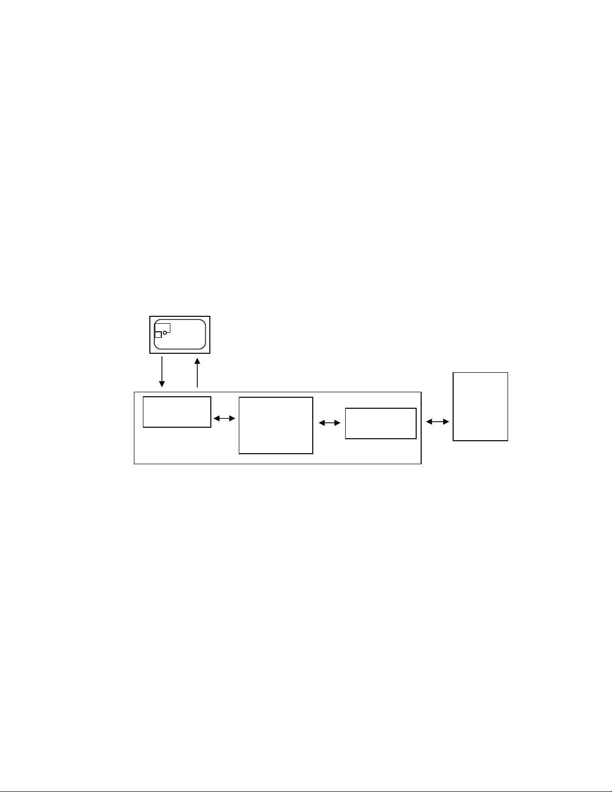
Fig. 1.2.a Block diagram: High Frequency Identification technology (RFID)
The multi-protocol RF Write/Read module is built-in in the printers paper path.
To use the RFID capabilities of this printer, you will need the appropriate
RFID media. This media includes the label, backing, and an RFID
transponder inlay encased by the label material.
The commands for the RFID functions are sent like print data via the
active data channel (Centronics, USB, Ethernet,...).
The ID of the label (Transponder Identification number) can be read in
order to be transmitted to the host via the printer's status channel.
This allows a clearly assignment of the specific label identification
number to the information printed on this label.
_______________________________________________________________________________________________
MICROPLEX Operator’s Manual LOGIJET T4 /T6 /RFID Edition 1.3
Energ
HF and
analog
circuit
Controller
Host
system

Introduction 9
_______________________________________________________________________________________________
Additionally the MICROPLEX firmware function "Status Out" provides the
possibility to get information on the printer status (paper jam, offline, ...)
and on the print job process (idle, busy, page printed,...).
1.3. Fundamentals of Thermal Printing
The thermal print technology enables a quiet and fast print process with a
high resolution output. The printhead produces the image by heating
single elements (dots). So you need a special ribbon (thermal transfer
printing) or a special kind of paper (thermal direct printing).
While thermal transfer printing the dots touch the thermal ribbon so that
the heating of particular dots leads to a partial melting of the ribbon. Due
to the contact with a media (future carrier of the information, for example
paper) this leads to a transfer of the image onto the media.
While thermal direct printing the dots touch the thermal paper directly.
The dyes and developers within the paper respond to the heat of
particular dots, change their colour to black and so the wanted image
emerges.
The LOGIJET T4 /T6 /RFID printers can be used for both methods of
printing.
_______________________________________________________________________________________________
MICROPLEX Operator’s Manual LOGIJET T4 /T6 /RFID Edition 1.3

10 Introduction
_______________________________________________________________________________________________
1.4. Conventions
!
OFFL.
blue colored text
[Menu Level 1 ]
To find the requested information more quickly and to
understand instructions more easily, the following conventions
are used:
This symbol refers to a possible source of danger. If you do not
pay attention to this information, injuries may result, the function
of the printer could be reduced or objects could be damaged.
This symbol refers to important hints and suggestions on using
the printer. Disregarding these hints might cause problems with
the printer or within the environments.
This symbol shows a key of the control panel. Such symbols will
be used in this manual whenever keys have to be pressed in
order to activate certain functions.
Link to another chapter or a different document. By clicking the
blue colored text you'll enter the concerning chapter or
document.
This symbol represents messages shown in the display (panel).
_______________________________________________________________________________________________
MICROPLEX Operator’s Manual LOGIJET T4 /T6 /RFID Edition 1.3

Introduction 11
_______________________________________________________________________________________________
1.5. CE - Conformity
The manufacturer hereby declares that the device complies with
the guideline RL 89/336/EWG for information technology
devices.
The determinations of the product standard concerning high
frequency interferences of information technology devices EN
55022, class A/DIN VDE 0878 (electromagnetic interference)
are complied.
Also the generic standard EN 50082-1/DIN VDE 0839 for
interference strength is complied.
The LOGIJET T4 RFID and LOGIJET T6 RFID printers incorporate
an integrated compact reader (RF Write/Read module).
The Declaration of Conformity can be found in section
8.1 Integrated RF Write/Read module.
1.6. General Safety Regulations
This equipment generates, uses, and can radiate radio frequency
energy and, if not installed and used in accordance with the
instruction manual, may cause harmful interference to radio
communications. Incorrect operation of this equipment in a
residential area is likely to cause harmful interference in which
case the user will be required to correct the interference at his
own expense.
_______________________________________________________________________________________________
MICROPLEX Operator’s Manual LOGIJET T4 /T6 /RFID Edition 1.3

12 Introduction
_______________________________________________________________________________________________
This MICROPLEX product and its consumables are designed
and tested according to strict safety standards.
Heeding the following instructions ensures secure operation:
- Please make sure your electricity source is appropriately
grounded.
- Install the device on solid and level ground.
- Only trained staff are authorized to transport the equipment.
- Only use consumables which are specially developed for this
device.
- Using unsuitable consumables may cause a reduction of output
quality or damages to the device.
- Ensure no liquids get on or into the device.
- Do not remove any cover or safety device fastened by screws.
- Do not remove or bridge over any safety device.
- Do not push anything into the ventilation apertures.
- Never carry out installations, cleanings or maintenance
operations which are not described in this manual. This should
only be done by MICROPLEX authorized service personnel.
_______________________________________________________________________________________________
MICROPLEX Operator’s Manual LOGIJET T4 /T6 /RFID Edition 1.3
Introduction 13
_______________________________________________________________________________________________
- Be careful when operating equipment with opened cover
hoods (setting-up work or service). Rotating parts can cause
injury , and it is also possible for hair, clothing, jewellery,
etc. to be caught in the machinery.
Ribbon and material should only be inserted and changed by
specially instructed personnel.
- Optional device components may only be installed by
authorized personnel, and in accordance with the
appropriate assembly and usage regulations.
- The cutter may only be installed by trained personnel.
- Only attach or remove the printhead when the device is
switched off.
After switching off the device, wait at least 3 minutes before
removing the printhead.
- Only plug in or remove interface connectors when the device
is switched off.
In order to disconnect the printer quickly from the main power
in case of emergency please note the following:
- For connected printers with plugs, the power-outlet should
be installed near the printer and easily within reach.
- For permanently connected printers, an easily accessible
emergency power-off switch should be installed close to the
printer.
- Please do not conceal any disconnect devices with the
printer or other objects.
- After switching off the device, wait at least 15 seconds
before the device is switched on again.
- Please follow all the information and hints directly attached
to the device and/or described in this manual.
_______________________________________________________________________________________________
MICROPLEX Operator’s Manual LOGIJET T4 /T6 /RFID Edition 1.3

14 Installation
_______________________________________________________________________________________________
2. Installation
2.1. Printer Unpacking
1. Open the box and remove the accessory parts.
Printer
Box contains
accessories
Fig. 2.1.a Printer in the shipping box
2. Take the printer and lift it out the box carefully. Get
somebody to hold the box when removing the printer.
Take hold of the printer from the bottom.
Do not use other parts of the printer (e.g. plastic parts at the
printer's front or rear side ...) to lift the device!
_______________________________________________________________________________________________
MICROPLEX Operator’s Manual LOGIJET T4 /T6 /RFID Edition 1.3

Installation 15
_______________________________________________________________________________________________
Fig. 2.1.b Lifting the printer
3. Remove the foil covering the printer.
4. Place the printer onto a suitable base (see section 2.3).
Please retain the original packing materials in case the printer
has to be transported in the future.
_______________________________________________________________________________________________
MICROPLEX Operator’s Manual LOGIJET T4 /T6 /RFID Edition 1.3

16 Installation
_______________________________________________________________________________________________
2.2. Check List
First of all place the printer and the accessories onto a level
surface until the definitive location is chosen.
Please make sure that all items are included and that there are
no defects.
Immediately inform your supplier of any damage.
Open the cardboard box carefully and check the contents:
1. Printer LOGIJET T4 /T6 /RFID
2. Power cord
3. Data cable (USB)
4. CD containing:
• Operator’s Manual for LOGIJET T4 /T6 /RFID
• Print drivers
• IDOL Programming Manual
Fig. 2.2.a Accessories
_______________________________________________________________________________________________
MICROPLEX Operator’s Manual LOGIJET T4 /T6 /RFID Edition 1.3

Installation 17
_______________________________________________________________________________________________
2.3. Printer Installation
- The chosen location should be well-ventilated, clean and dry.
- Damaging environmental factors such as metal vapors, oil mist,
corroding lixivium or the like must not come into contact with
the printer.
- Position the printer on solid and level ground.
- Do not exposure the printer to shocks or vibrations.
- The printer and socket have to be easily accessible.
- The printer should not be located near volatile or combustible
materials (e.g. a curtain).
- The printer must be connected to an appropriate AC power
source 120V AC/60 Hz (North America) or 230V/50 Hz
(Europe, United Kingdom e.g.). The power source must be
properly grounded. The socket and power cords must not be
damaged.
- Use the printer only within the allowed fluctuation range of
±10%.
- The voltage support must not be impaired by interference.
- In order to run the printer reliably, please maintain the
following environmental conditions:
Temperature: +5°C to +40°C (operating)
-20°C to +50°C (storage temperature)
Relative atmospheric humidity: 30% to 85% (without
condensation)
- Do not expose the printer to abrupt temperature changes
(heating, window or air condition).
- The printer should not be exposed to direct sunlight.
_______________________________________________________________________________________________
MICROPLEX Operator’s Manual LOGIJET T4 /T6 /RFID Edition 1.3

18 Installation
_______________________________________________________________________________________________
2.4. Printer Components
Main view:
Display
Control Panel
LCD grafics display; 3
keys; displays printer
operation status, enables
settings via the menu.
Cover
Open to insert material
and foil.
Window
Check the material / foil
supply without opening the
cover.
Rear view:
Fig. 2.4.a Main view of the printer
Centronics interface
USB interface
Ethernet interface
Power switch
Input power
connector
Fig. 2.4.b Rear view of the printer
_______________________________________________________________________________________________
MICROPLEX Operator’s Manual LOGIJET T4 /T6 /RFID Edition 1.3

Installation 19
_______________________________________________________________________________________________
Cover
Label
supply
guide
Control
panel
Printer
mechanism
Lower cover
Fig. 2.4.c Printer opened
Printhead
pressure lever
Label roll
bar
Dispense
sensor
Ribbon
supply shaft
Tear off edge
Ribbon
Platen roller
rewind shaft
Fig. 2.4.d Details printer mechanism
_______________________________________________________________________________________________
MICROPLEX Operator’s Manual LOGIJET T4 /T6 /RFID Edition 1.3

20 Media and Ribbon Requirements
_______________________________________________________________________________________________
3. Media and Ribbon Requirements
Since print quality is affected by media and ribbon, printing speeds, and
printer operation modes, it is very important to run tests for your applications.
Fig. 3.a Labels
To use the RFID capabilities of this printer, you will need the appropriate RFID
media. This media includes the label, backing, and an RFID transponder inlay
encased by the label material.
High quality RFID labels are recommended to ensure against premature
printhead wear.
We strongly recommend the use of MICROPLEX supplies for continuous highquality printing.
_______________________________________________________________________________________________
MICROPLEX Operator’s Manual LOGIJET T4 /T6 /RFID Edition 1.3

Basic Operation Sequences 21
_______________________________________________________________________________________________
4. Basic Operation Sequences
4.1. Overview
start
print process selecting
see chapter 7
th e rm a l d ire c t
ribb o n rem o va l
see chapter 5
media loading
p rin th ea d p re ssu re a d ju stin g
media (material) setting
label
p a ge le n g th / p a p er w id th se tting
RFID-M ode selection (o ption a l)
see chapter 8
th e rm a l tra n s fe r
ribbon loading
see chapter 5
see chapter 5
see chapter 5
see chapter 7
continuous
see chapter 7
Comm unication protocol setting
see chapter 8
Transp o n d er po sition a d justing
see chapter 8
m a rg in se ttin g
see chapter 7
_______________________________________________________________________________________________
MICROPLEX Operator’s Manual LOGIJET T4 /T6 /RFID Edition 1.3

22 Basic Operation Sequences
_______________________________________________________________________________________________
If the panel settings above shall be effective permanently (that
!
means they do not have to be put in again after a printer
OFF/ON) the setting values can be saved permanently by
operating the ENTER key two times.
An output of the current setting values can be generated using the
"Printing the Status Sheet“ panel function (see section 7.6).
Detailed information on the operations above and to further
functions of the printer LOGIJET T4 /T6 /RFID can be found in the
following chapters.
_______________________________________________________________________________________________
MICROPLEX Operator’s Manual LOGIJET T4 /T6 /RFID Edition 1.3

Handling of Consumables 23
_______________________________________________________________________________________________
5. Handling of Consumables
!
Pay attention to the following safety instructions and the instructions
listed in section 1.4, too!
Safety instructions:
- The cutter (optional device of your printer) can cause injuries if the
printer is operated incorrectly.
- There is a danger of fingers, hair, clothing, jewellery etc. being
drawn into the machine in the vicinity of the material transport unit.
- Be careful when operating equipment with opened cover hoods
(setting-up work or service). Rotating parts can cause injury, and it
is possible for hair, clothing, jewellery, etc. to be caught in the
machinery.
- Print material should only be inserted and changed by specially
instructed personnel.
For thermal direct printing it is not allowed to load a ribbon to avoid
damaging the printhead. Make sure your settings using the control
panel and display respectively via interface (see chapter 6 and 7) fit
to the printer implementation (ribbon inserted /not inserted).
Ribbon and material should only be inserted/exchanged by specially
instructed personnel.
_______________________________________________________________________________________________
MICROPLEX Operator’s Manual LOGIJET T4 /T6 /RFID Edition 1.3

24 Handling of Consumables
t
_______________________________________________________________________________________________
5.1. Winding Diagram
Ribbon rewind shaft
Ribbon supply shaf
Print roller
Printhead
pressure lever
Material guide
Material roll (Label)
Fig. 5.1.a Winding directions of material and ribbon (here: ink inside the roll)
The diagram above shows the usual winding directions of material and
ribbon.
Pay attention to the different ribbon roll winding directions described in
section 5.3.1 Ribbon Loading. The figure above shows the winding
directions for “Ink inside the roll” ribbons. Also pay attention to the
instructions located on the inside of the printer hood.
_______________________________________________________________________________________________
MICROPLEX Operator’s Manual LOGIJET T4 /T6 /RFID Edition 1.3

Handling of Consumables 25
_______________________________________________________________________________________________
5.2. Roll-Fed Media Handling
5.2.1. Tear Off Media Loading
To load roll-fed media for tear off respectively for further external
processing go on like this:
The tear off roll-fed media is easier to insert if the end is gored
before inserting as shown in figure 5.2.1.a (when using a new
roll you should first remove the protection foil if necessary and
discard one full turn of the media).
!
Fig. 5.2.1.a Goring the tear off roll-fed media
1. Switch the printer to OFF LINE mode.
2. Open the printer hood.
_______________________________________________________________________________________________
MICROPLEX Operator’s Manual LOGIJET T4 /T6 /RFID Edition 1.3
26 Handling of Consumables
_______________________________________________________________________________________________
Fig. 5.2.1.b Opening the printer hood
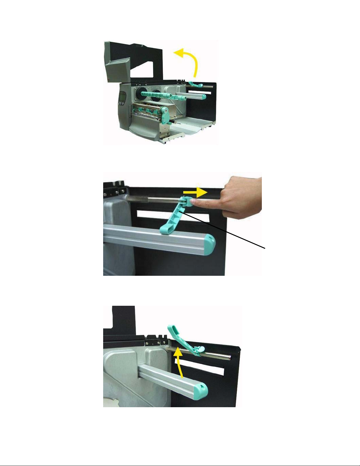
3. Pull the label supply guide rightward.
Fig. 5.2.1.c Pulling the label supply guide rightward.
4. Swivel the label supply guide upward.
Fig. 5.2.1.d Swivelling the label supply guide upward
Label supply
guide
_______________________________________________________________________________________________
MICROPLEX Operator’s Manual LOGIJET T4 /T6 /RFID Edition 1.3

Handling of Consumables 27
_______________________________________________________________________________________________
5. The media roll must turn counterclockwise when unwinding.
Take the Tear off roll-fed media and hold it in the
corresponding way.
6. Slide the media roll onto the label roll bar all the way back
to the printer’s inner wall.
Label
supply
guide
Label roll
bar
Fig. 5.2.1.e Inserting the media roll
7. Swivel the label supply guide downward.
8. Slide the label supply guide in towards the label roll (as
shown in the right
figure below).
X
False
Fig. 5.2.1.f Please refer to the right photo!
_______________________________________________________________________________________________
MICROPLEX Operator’s Manual LOGIJET T4 /T6 /RFID Edition 1.3
OK

28 Handling of Consumables
_______________________________________________________________________________________________
9. Avoid pushing the label supply guide in too far or you will
damage the edge of the label stock.
Fig. 5.2.1.g Setting the label supply guide to the right position
10. Release the printhead pressure lever.
Fig. 5.2.1.h Pull the printhead pressure lever out and swivel it upward
(counterclockwise).
11. Slide the material guide to its outermost position. (Compare
figure 5.2.1.j).
12. Feed the label through under the label tension plate (under
the moveable sensor) to the tear off bar.
_______________________________________________________________________________________________
MICROPLEX Operator’s Manual LOGIJET T4 /T6 /RFID Edition 1.3

Handling of Consumables 29
_______________________________________________________________________________________________
Label
tension
Fig. 5.2.1.i Inserting the media
13. Align the media to ensure a straight transport.
14. Slide the material guide inwards until it contacts the edge
of the media, without deforming the media.
plate
Fig. 5.2.1.j Setting the material guide
_______________________________________________________________________________________________
MICROPLEX Operator’s Manual LOGIJET T4 /T6 /RFID Edition 1.3

30 Handling of Consumables
_______________________________________________________________________________________________
15. Use the setting knob to adjust the sensor position (light
barrier). (If you turn the setting knob clockwise, the sensor
will move rightward.)
Setting knob
Fig. 5.2.1.k Adjusting the sensor position
16. The right position is found when the pointer is located
above the material’s gap.
Pointer
Fig. 5.2.1.l The pointer indicates the sensor position
_______________________________________________________________________________________________
MICROPLEX Operator’s Manual LOGIJET T4 /T6 /RFID Edition 1.3

Handling of Consumables 31
_______________________________________________________________________________________________
17. If you want to print using the thermal direct process, now
close the pressure lever (Fig. 5.2.1.m).
To print using the thermal transfer process, you still need to
insert ribbon.
Printhead
pressure lever
Fig. 5.2.1.m Closing the pressure lever
Pay attention to the following safety instructions!
Safety instructions:
- The cutter (optional) can cause injuries if the printer is
operated incorrectly.
- There is a danger of fingers, hair, clothing, jewellery etc.
being drawn into the machine in the vicinity of the ribbon
and media transport unit.
18. Close the hood of the printer.
_______________________________________________________________________________________________
MICROPLEX Operator’s Manual LOGIJET T4 /T6 /RFID Edition 1.3

32 Handling of Consumables
_______________________________________________________________________________________________
5.2.2. Media Removal
1. Switch the printer to OFF LINE mode.
2. Open the hood of the printer.
3. Release the printhead pressure lever to remove the media
(see section 5.1 Winding Diagram) and at the same time
pull away the material to the rear.
4. Rotate the tear off roll-fed media roll clockwise until the free
end of the media is winded up.
5. Remove the roll with the tear off roll-fed media (if necessary
protect the media against unintentional unwinding first).
6. Close the hood of the printer.
_______________________________________________________________________________________________
MICROPLEX Operator’s Manual LOGIJET T4 /T6 /RFID Edition 1.3

Handling of Consumables 33
_______________________________________________________________________________________________
5.3. Handling of Ribbon (Foil)
5.3.1. Ribbon Loading
If you want to operate the printer in the thermal transfer mode a
printer ribbon has to be used (compare section 1.1).
Make sure you always use a printer ribbon being wider than the
media to print on. In the case of printing on abrasive media
printhead damaging can be avoided this way.
To set the ribbon go on like this:
1. Switch the printer to OFF LINE mode.
2. Open the printer hood.
3. Release the printhead pressure lever.
!
Fig. 5.3.1.a Pull the printhead pressure lever out and swivel it upward
(counterclockwise).
4. Take the ribbon roll and remove the protection foil, if
necessary (by unwinding it and cutting it off).
5. Find out the right winding direction for your ribbon roll:
_______________________________________________________________________________________________
MICROPLEX Operator’s Manual LOGIJET T4 /T6 /RFID Edition 1.3

34 Handling of Consumables
_______________________________________________________________________________________________
Ribbon outside
(Ink outside the roll).
Ribbon inside
(Ink inside the roll).
Fig. 5.3.1.b Different ribbon roll winding directions
6. Slide the ribbon roll onto the ribbon supply shaft all the way
back to the printer’s inner wall.
Ribbon sleeve
Ribbon roll
Fig. 5.3.1.c Inserting the ribbon roll and the empty ribbon sleeve
7. Slide the empty ribbon sleeve (ribbon core) onto the ribbon
rewind shaft.
8. Route the ribbon around the printhead without folds.
!
_______________________________________________________________________________________________
MICROPLEX Operator’s Manual LOGIJET T4 /T6 /RFID Edition 1.3
Be sure you don’t feed the ribbon underneath the moveable sensor.

Handling of Consumables 35
t
_______________________________________________________________________________________________
Ribbon supply
shaft
Ribbon rewind
Ribbon
Printhead
shaft
!
Fig. 5.3.1.d Feeding through the ribbon below the printhead
9. Route the ribbon to the rewinding mandrel and fasten it to
the ribbon sleeve (turn up the ribbon once so that the
adhesive part at the beginning of the ribbon can be used).
Make sure that the ribbon rewind direction is correct. (Compare
figure 5.3.1.b.)
Fig. 5.3.1.e Tautening the ribbon by turning the ribbon rewind shaft
_______________________________________________________________________________________________
MICROPLEX Operator’s Manual LOGIJET T4 /T6 /RFID Edition 1.3
Rewind shaf

36 Handling of Consumables
_______________________________________________________________________________________________
10. Check that the ribbon has no folds and is running straight.
If necessary, tauten the ribbon by turning the rewind shaft.
11. Swivel the printhead pressure lever clockwise back to its
original position making sure it clicks into place.
Printhead
pressure lever
Fig. 5.3.1.f Locking the pressure lever
_______________________________________________________________________________________________
MICROPLEX Operator’s Manual LOGIJET T4 /T6 /RFID Edition 1.3

Handling of Consumables 37
_______________________________________________________________________________________________
5.3.2. Ribbon Tension Adjustment
A)
Increasing the ribbon tension
Due to differences in ribbon material, ribbon wrinkles may
occur during printing.
To solve this problem the ribbon tension has to be increased:
1. Push the adjusting ring of the ribbon rewind shaft towards
the ribbon roll.
2. Then turn the adjusting ring of the ribbon rewind shaft
clockwise to increase the ribbon tension, while you hold
the ribbon roll with the other hand.
#
"
Fig. 5.3.2.a Adjusting the ribbon tension at the ribbon rewind shaft
Adjusting ring
_______________________________________________________________________________________________
MICROPLEX Operator’s Manual LOGIJET T4 /T6 /RFID Edition 1.3

38 Handling of Consumables
_______________________________________________________________________________________________
3. Push the adjusting ring of the ribbon supply shaft towards the
ribbon roll.
4. Then turn the adjusting ring of the ribbon supply shaft
clockwise to increase the ribbon tension, while you hold
the ribbon roll with the other hand.
#
!
"
Fig. 5.3.2.a Adjusting the ribbon tension at the ribbon supply shaft
5. Check that the ribbon has no folds and is running straight.
Optimize your adjustment of the ribbon tension, if need be.
Check to see that slack and wrinkles on the ribbon are removed
completely. Do not be afraid to ’waste’ a little extra ribbon to
ensure the ribbon is running correctly and wrinkle-free.
Adjusting ring
_______________________________________________________________________________________________
MICROPLEX Operator’s Manual LOGIJET T4 /T6 /RFID Edition 1.3

Handling of Consumables 39
_______________________________________________________________________________________________
B) Decreasing the ribbon tension
If narrow ribbon is used (ribbon widths of less than 2”, e.g.), the
printer might have a problem feeding the material.
Moreover, the ribbon maybe difficult to be removed caused by a
high ribbon tension. Excessive values of ribbon tension may
cause shapechanges of the ribbon, too.
To solve this problems the ribbon tension has to be decreased:
1. Push the adjusting ring of the ribbon rewind shaft towards
the ribbon roll. See figure 5.3.2.a.
2. Then turn the adjusting ring of the ribbon rewind shaft
counterclockwise to decrease the ribbon tension, while
you hold the ribbon roll with the other hand.
3. Push the adjusting ring of the ribbon supply shaft towards
the ribbon roll. See figure 5.3.2.b.
4. Then turn the adjusting ring of the ribbon supply shaft
counterclockwise to decrease the ribbon tension, while
you hold the ribbon roll with the other hand.
5. Check that the ribbon has no folds and is running straight.
Optimize your adjustment of the ribbon tension, if need be.
Check to see that slack and wrinkles on the ribbon are removed
completely. Do not be afraid to ’waste’ a little extra ribbon to
ensure the ribbon is running correctly and wrinkle-free.
!
_______________________________________________________________________________________________
MICROPLEX Operator’s Manual LOGIJET T4 /T6 /RFID Edition 1.3

40 Handling of Consumables
_______________________________________________________________________________________________
5.3.3. Ribbon Removal
The following steps are necessary if you want to switch from
printing in the thermal transfer mode to printing in the thermal
direct mode.
In case only a used-up ribbon has to be removed the steps 5 and
6 have to be omitted.
1. Switch the printer to OFF LINE mode.
2. Open the the printer hood.
3. Release the printhead pressure lever.
4. The core of a used-up ribbon can be removed by pulling it
from the ribbon supply shaft.
Used-up
ribbon
Empty ribbon
sleeve
(ribbon core)
Ribbon rewind
Fig. 5.3.3a Removing used-up ribbon
shaft
5. If the inserted ribbon is not used-up, cut it close to the
ribbon rewind shaft.
6. Rotate the ribbon supply shaft until the free end of the
ribbon is winded up.
_______________________________________________________________________________________________
MICROPLEX Operator’s Manual LOGIJET T4 /T6 /RFID Edition 1.3

Handling of Consumables 41
_______________________________________________________________________________________________
The unused ribbon can remain within the device until it is
used for the next thermal transfer operation (if necessary
protect the ribbon against unintentional unwinding).
The ribbon has to be loaded as described in section
5.3.1.
ribbon is winded up.
dispose it according to the rules.
!
7. Rotate the rewind shaft until the free end of the used-up
8. Remove the used-up ribbon from the rewind shaft and
The media for thermal direct printing has to be loaded as
described in section 5.2.1.
_______________________________________________________________________________________________
MICROPLEX Operator’s Manual LOGIJET T4 /T6 /RFID Edition 1.3
42 Handling of Consumables
_______________________________________________________________________________________________
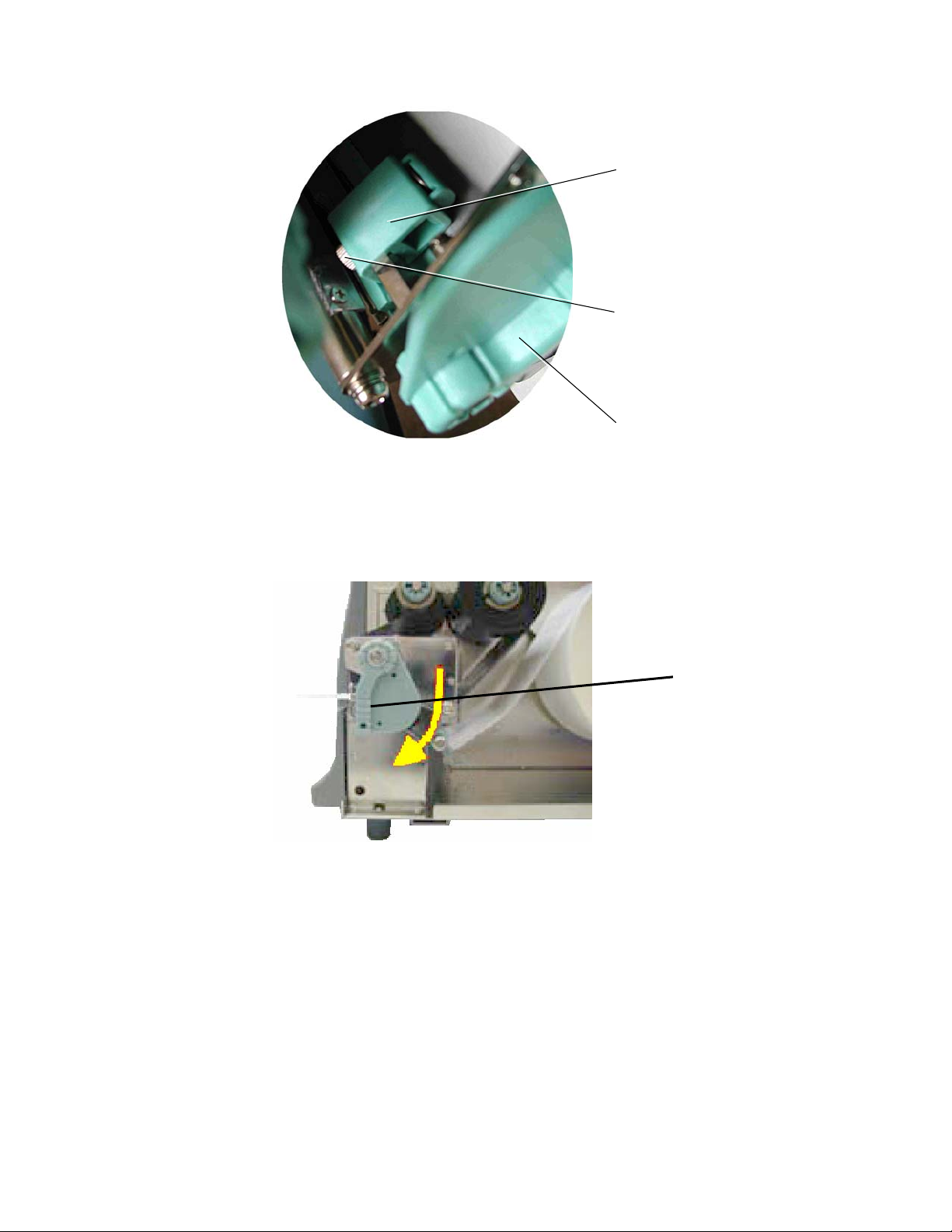
5.4. Printhead Pressure Adjusting
Different material width and/or material thickness have an effect
on the contact pressure of the thermal bar on the platen roller.
To allow a compensation of this influences, the position of the
spring boxes and the contact pressure are both adjustable.
The spring boxes are located above the printhead:
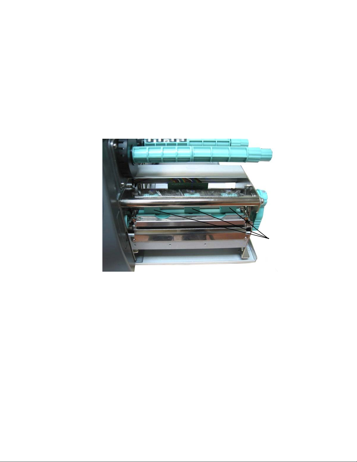
Spring boxes
Fig. 5.4.a Printhead contact pressure: position of the spring boxes
Please note:
- Printing should always be carried out with the lightest contact
!
- Excessive contact pressure can result in premature wearing of
pressure possible for creating a satisfactory print quality. This
protects the printhead and the entire device.
the printhead.
- See also section 9.2 Printhead Exchange
and section 9.3 Adjusting the Right Pressure Value.
_______________________________________________________________________________________________
MICROPLEX Operator’s Manual LOGIJET T4 /T6 /RFID Edition 1.3

Handling of Consumables 43
_______________________________________________________________________________________________
1. Open the printer hood.
2. Release the printhead pressure lever.
Fig. 5.4.b Pull the printhead pressure lever out and swivel it upward
(counterclockwise).
3. Please adjust the lateral positions of the thermal printhead
spring boxes in accordance to the current material width.
Normally, the wider the paper, the farther the spring boxes on
the right side have to be positioned from the center wall (and
vice versa for small labels).
Fig. 5.4.c Lateral shifting of the spring boxes
_______________________________________________________________________________________________
MICROPLEX Operator’s Manual LOGIJET T4 /T6 /RFID Edition 1.3
44 Handling of Consumables
_______________________________________________________________________________________________
Spring
box
Setting screw
for the printhead
pressure
Printhead
pressure lever
Fig. 5.4.d Detailed picture of a spring box
4. Swivel the printhead pressure lever clockwise back to its
original position making sure it clicks into place.
Printhead
pressure lever
Fig. 5.4.e Locking the pressure lever
The following picture helps you to locate the setting screws for
the printhead pressure:
_______________________________________________________________________________________________
MICROPLEX Operator’s Manual LOGIJET T4 /T6 /RFID Edition 1.3

Handling of Consumables 45
_______________________________________________________________________________________________
Setting screws
for the
printhead
pressure
Fig. 5.4.f Adjusting the printhead's contact pressure
5. Every spring box is provided with a setting screw to enable
printhead pressure adjustment.
Be careful when using a flat blade screwdriver to avoid
damaging the printer!
Turning the screw clockwise increases the printhead’s contact
pressure.
6. Carry out a test print.
Note: If one side of the printed material is not being printed
clearly, or if ribbon wrinkles occur, then adjust the
thermal printhead spring box position or pressure
appropriately to cure the problem.
!
_______________________________________________________________________________________________
MICROPLEX Operator’s Manual LOGIJET T4 /T6 /RFID Edition 1.3

46 Control Panel
________________________________________________________________________________________________
6. Control Panel
6.1. Attaching the Printer to a Computer
1. Make sure the printer, computer, and any other attached devices
are turned off and unplugged.
2. Use a proper interface line to connect the printer to the computer or to
attach the printer to the network.
The printers LOGIJET T4 /T6 /RFID are provided with several interfaces; see
figure 2.4.b and chapter 12 Specifications for more information.
6.2. Turning on the Printer
First, please notice the instructions given in chapter 5 Handling of
Consumables.
!
1. Plug one end of the printer power cord into the socket at the back of the
printer and the other end into a properly grounded outlet.
2. Turn on the printer. The power switch is located at the rear side of the
printer (see section 2.4 Printer Components).
As soon as the printer’s warm up phase is finished the printer goes into
the ON LINE mode. A status message and the name of the printer are
displayed.
_______________________________________________________________________________________________
MICROPLEX Operator’s Manual LOGIJET T4 /T6 /RFID Edition 1.3

Control Panel 47
________________________________________________________________________________________________
6.3. Control Panel View
Power
ON LINE
LOGIJET T6 RFID
OFFL.
FEED
Ready
PAUSE
Error
CANCEL
LEDs
(3 units)
Display
Current designation
/meaning of the
function keys
Function keys
(3 units)
_______________________________________________________________________________________________
MICROPLEX Operator’s Manual LOGIJET T4 /T6 /RFID Edition 1.3

48 Control Panel
________________________________________________________________________________________________
6.4. Function of the Control Panel Elements
Display
The display (LCD-panel) serves to show the printer’s status messages.
The lowest line of the display shows the current designation of the panel
keys.
!
Control Panel Keys
!
*) This innovation was created to make this printers — in spite of their small number of
panel keys — flexible in operation.
_______________________________________________________________________________________________
MICROPLEX Operator’s Manual LOGIJET T4 /T6 /RFID Edition 1.3
Variable key designations *)
The meaning (function) of the three panel keys of this printer changes
depending on the current position in the menu structure.
Please note: In the lowest line of the display the current
designation of the panel keys is displayed in time.

Control Panel 49
________________________________________________________________________________________________
OFFL.
Example:
Is the printer turned OFF LINE with this key (OFFL., panel key in the
middle; compare section 6.3 Control Panel View), the key
designations change as follows:
Power
OFFLINE
LOGIJET T6 RFID
FEED ONL. MENU
FEED
Ready
PAUSE
Error
CANCEL
Current
meaning of the
function keys
MENU
If a cutter (option) is installed, the key designation CUT appears (default).
Use the key combinations MENU + CUT or MENU + FEED to change the key designation (toggle).
The MENU key (panel key on the right) is used to enter menu level 1.
Now the following key designations are available:
Power
OFFLINE
Menu Level 1
NEXT ENTER ESC
FEED
Ready
PAUSE
Error
CANCEL
Current
meaning of the
function keys
_______________________________________________________________________________________________
MICROPLEX Operator’s Manual LOGIJET T4 /T6 /RFID Edition 1.3

50 Control Panel
________________________________________________________________________________________________
Key combinations
The panel key on the right can be combined with other keys (similar to
the Shift key on a PC keyboard), to reach additional key designations.
This is how you get access to the key designations PREVIOUS
(PREV) and VALUE- (VAL-).
Example:
The key NEXT is used to move forward in the menus.
NEXT ENTER ESC
FEED
PAUSE
CANCEL
Current
meaning of the
function keys
ESC
NEXT
+
Using the following key combination enables to move one or more
steps back:
Press and hold the ESC key, and then press the NEXT key additionally.
Hint: The new key designation PREVIOUS (left panel key, see figure
below) will not be displayed until the ESC key is pressed for a
longer time.
PREV ENTER
FEED
PAUSE
CANCEL
Current
meaning of the
function keys
The descriptions above are valid in a similar manner for getting access
!
_______________________________________________________________________________________________
to the key designation VAL-. (Alternation from VAL+ to the key
designation VAL- to enable the reduction of function values.)
MICROPLEX Operator’s Manual LOGIJET T4 /T6 /RFID Edition 1.3

Control Panel 51
________________________________________________________________________________________________
6.5. Configuration via the Control Panel
You can use the control panel to change the printer configuration
and customize your printer to meet your specific needs.
In addition a software (called IP printADMIN
for the LOGIJET T4 /T6 /RFID printers to allow a printer
configuration via Ethernet.
The controller has its integrated website with information on the
printer status and the printjob status.
Chapter 7 (Panel Functions) describes how to reach the particular
printer functions via the panel.
T e m p o r a r y changes in printer configuration are effective
only as long as the printer stays turned on. To select such
changes temporarily, the user must terminate the change of
function by pressing the ENTER key one single time.
P e r m a n e n t changes in printer configuration are active
each time the printer is turned on again. To select such changes
permanently, the user must terminate the change of function by
pressing the ENTER key two times.
An output of the current printer values can be generated using
the “Printing the Status Sheet“ panel function (see section 7.6).
) will be available
_______________________________________________________________________________________________
MICROPLEX Operator’s Manual LOGIJET T4 /T6 /RFID Edition 1.3

52 Control Panel
________________________________________________________________________________________________
6.6. Menu Structure
Access to the menu structure is possible as soon as the printer is turned
OFF LINE and the MENU key was pressed.
The menu structure of the printers LOGIJET T4 /T6 /RFID is arranged in different levels:
ON LINE mode
OFFL.
$
OFF LINE mode
MENU
$
Menu Level 1
CUT
FEED
Paper Menu
Configuration
Page Menu
Engine
Network
Status Sheet
Font List
Hexdump
Normal Print/FF
File Management
Print-Files
Directory
Cancel Job
Menu Page
Sliding Pattern
Buffe r Dump
Paper Size
Page Length
Measure length
in mm
in inch
in dot
Auto.Measurement
Paper Width
in mm
in inch
in dot
Change by IP
Two-Up Mode
Print Direction
Material
Label
Continuous
Interfa ce
Timeout
Emulation
Language
Transparent Code
Input Bu ffer
Config. Word
User Config.
Select
Define
Factory Default
RFM
Key lock
Acoustic Signals
Key tone
Error tone
Extended Menu
Time setting
Date setting
Font Number
Orie ntation
Symbol Code
Line Spacing
Char. Spacing
Line Termination
Margin
Left
from Right
Top
from Bottom
Printspeed
Contrast
Process
Ima ge X -Pos.
Ima ge Y -Pos.
Sync. Menu
Sync.Sens.Type
Auto.Sens.Adj.
Sync.Sens.Level
Syn c.Sens .O ffset
Sync.Sens.Logic
Sensor Test
Tea rO ff M en u
Tea rO ff M od e
Tea rO ff Position
Print Mode
RFID Menu
RFID Mode
Autom. Read ID
Autom. ID Gen.
Tag Position
Search Tag Pos.
Protocol
Bit Rate
Timeout
RFID Test
Last E rror
Service Mode
Dot-Test
Periph. Device
Head Resistance
Timeout
IP Assign
Off
DHCP
Manual
IP Add ress
Subnet Mask
Gateway
Duplex/Speed
Autonegotiation
10MB HalfDuplex
10MB FullDuplex
100MB HalfDuplex
100MB FullDuplex
This panel function allows the user to choose a reduced menu instead
of the extended menu shown above.
_______________________________________________________________________________________________
MICROPLEX Operator’s Manual LOGIJET T4 /T6 /RFID Edition 1.3

Control Panel 53
________________________________________________________________________________________________
Selecting positions in the menu structure:
OFFL.
MENU
NEXT
This symbol shows the key designation OFFLINE.
The printer is turned OFF LINE with this key.
With this key you get into the first menu level of the menu
structure.
The NEXT key is used to move forward within a menu level.
ESC
NEXT
+
["Menu Level "]
ENTER
["Function"]
The combination of this two keys is used to move one or more
steps back (PREVIOUS).
Press and hold the NEXT key to scroll forward quickly or press
and hold the key combination PREVIOUS to scroll backward.
Each menu item / sub-item within a menu level is shown in the
display of the control panel.
The ENTER key has two main functions. It gives the user access
to a particular menu and, once in the menu, it allows the user to
select a particular function.
_______________________________________________________________________________________________
MICROPLEX Operator’s Manual LOGIJET T4 /T6 /RFID Edition 1.3

54 Control Panel
________________________________________________________________________________________________
Functions / Changing of function values:
NEXT
ESC
NEXT
+
VAL+
ESC
VAL+
+
ENTER
[Save as Setup?]
ENTER
ESC
Within one function the value can be changed by pressing the NEXT
key or the combination of ESC + NEXT (= PREVIOUS).
In case of a multi-digit function value pressing the NEXT key switches
to the next position (digit) of the function value.
Pressing the key combination ESC + NEXT (= PREVIOUS) switches to
the previous digit of the function value.
Please note: If you press the ESC key although the absolute left digit
of the function value is still arrived, the changing
procedure will be cancelled and this moves you to the
next menu level above.
If you press the ENTER key although the absolute right
digit (digit 1) of the function value is still arrived, the
currently displayed function value is stored.
In case of a multi-digit function value the value of the currently chosen
digit can be changed by pressing the VAL+ key or the key
combination ESC + VAL+ (= VAL-).
By pressing the ENTER key the function values currently displayed
are confirmed respectively the selected function is activated (the
changes are saved until the next printer power off; this kind of
saving is called temporary).
After this you have to decide, if you want to save the changes
permanent (Save as setup).
To select such changes permanently, the user must press the
ENTER key one more time. These permanent changes in printer
configuration are active each time the printer is turned on again.
If the ESC key is pressed instead, the changes are only stored
temporary (not saved as setup).
(This key takes the user to the respective previous menu level).
_______________________________________________________________________________________________
MICROPLEX Operator’s Manual LOGIJET T4 /T6 /RFID Edition 1.3

Control Panel 55
________________________________________________________________________________________________
Return to the ON LINE mode:
ENTER
ESC
ONL.
A) In one step:
Press the ENTER key longer than 2 seconds (using the repeat
function). This switches the user directly to the ON LINE mode
from nearly any menu position.
B) Return to the ON LINE mode step by step:
Pressing the ESC key shortly takes the user to the respective
previous menu level.
Aim is to jump back to the OFF LINE mode, where the key
designation ONLINE is available.
_______________________________________________________________________________________________
MICROPLEX Operator’s Manual LOGIJET T4 /T6 /RFID Edition 1.3
56 Control Panel
________________________________________________________________________________________________
6.7. Syntax of Diagrams
OFFL.
MENU
ENTER
["Message"]
The control panel functions will be described using diagrams.
These diagrams show the course necessary in order to activate a
certain function.
First the elements of the diagram are explained:
The sequence on the left describes which keys have to be pressed
briefly in succession.
Please note: In the lowest line of the display the current
designation of the panel keys is displayed in time. (See
section 6.4 Function of the Control Panel Elements.)
In this example the OFFLINE key has to be pressed first. Then the
OFFLINE key is released and the MENU key has to be pressed.
Then the MENU key has to be released and the ENTER key has to
be pressed.
The ″Panel display″ column shows the display messages
corresponding to the sequences listed on the left.
In the column ″Notes″ explanations to particular operational steps
are given.
_______________________________________________________________________________________________
MICROPLEX Operator’s Manual LOGIJET T4 /T6 /RFID Edition 1.3

Panel Functions 57
________________________________________________________________________________________________
7. Panel Functions
For the panel functions described in the following text, the printer is
!
7.1. Print Process Selecting
This function allows to select the print process.
Description of this control panel function continues on the next page.
presumed to be turned on and in the ON LINE mode.
While thermal direct printing the device operates without ribbon,
direct thermal media is required.
While thermal transfer printing a ribbon is needed to transfer the
print contents onto the media (see chapter 5 Handling of
Consumables, too).
For thermal direct printing it is not allowed to insert a ribbon to
avoid damaging the printhead.
Make sure your settings match to the printer implementation (ribbon
inserted/not inserted).
_______________________________________________________________________________________________
MICROPLEX Operator’s Manual LOGIJET T4 /T6 /RFID Edition 1.3

58 Panel Functions
________________________________________________________________________________________________
OFFL.
MENU
NEXT
ENTER
NEXT
ENTER
NEXT
ENTER
ESC ENTER
ENTER
Panel display
[ON LINE ]
[OFF LINE ]
[Menu Level 1 ]
& & &
[Engine ]
[Printspeed ]
& & &
[Process ]
[Thermo direct ]
& & &
[Thermo transfer ]
[Save as Setup? ]
Notes
Turn the printer OFF LINE with this
key.
The MENU key gives the user access
to the menu structure.
Press the NEXT or PREVIOUS key
until [Engine] is displayed.
The menu item Engine is selected.
Press the NEXT or PREVIOUS key
until [Process] is displayed.
The menu item Process is selected.
Press the NEXT or PREVIOUS key
until the display message is
corresponding with the printer
implementation (ribbon inserted =
Thermo transfer e.g.).
The thermal transfer print process is
selected.
In addition this new value can be
saved as setup value (using the
ENTER key).
After this decision turn the printer
ON LINE again: Press the ENTER
key longer than 2 seconds.
_______________________________________________________________________________________________
MICROPLEX Operator’s Manual LOGIJET T4 /T6 /RFID Edition 1.3

Panel Functions 59
________________________________________________________________________________________________
7.2. Media Setting (Material; Label or Continuous)
This function allows to adjust the printer to the actual used material
(distinction between formatted media (label) and continuous media).
OFFL.
MENU
NEXT
ENTER
NEXT
ENTER
NEXT
ENTER
ESC ENTER
ENTER
Panel display
[ON LINE ]
[OFF LINE ]
[Menu Level 1 ]
& & &
[Paper Menu ]
[Paper Size ]
& & &
[Material ]
[Label ]
& & &
[Continuous ]
[Save as Setup? ]
Notes
Turn the printer OFF LINE with this
key.
The MENU key gives the user access
to the menu structure.
Press the NEXT or PREVIOUS key
until [Paper Menu] is displayed.
Press the NEXT or PREVIOUS key
until [Material ] is displayed.
Select sub-menu Material.
Press the NEXT or PREVIOUS key
until the statement shown by the
display corresponds to the inserted
media (Continuous e.g.).
The printer is adjusted to continuous
material.
In addition this new value can be
saved as setup value (using the
ENTER key).
After this decision turn the printer
ON LINE again: Press the ENTER
key longer than 2 seconds.
_______________________________________________________________________________________________
MICROPLEX Operator’s Manual LOGIJET T4 /T6 /RFID Edition 1.3

60 Panel Functions
________________________________________________________________________________________________
7.3. Page Length Adjustment
After inserting new material (e.g. paper) this function is used to adjust the printer to
the new page length.
Hint:
OFFL.
MENU
NEXT
ENTER
ENTER
ENTER
NEXT
ENTER
NEXT
ENTER
ESC
ENTER
_______________________________________________________________________________________________
MICROPLEX Operator’s Manual LOGIJET T4 /T6 /RFID Edition 1.3
Alternatively, the printer itself is able to measure the label length. See next sections.
Panel display
[ON LINE ]
[OFF LINE ]
Notes
Turn the printer OFF LINE with this key.
The MENU key gives the user access to the
[Menu Level 1 ]
& & &
[Paper Menu ]
[Paper Size ]
[Page Length ]
ENTER
[Measure Length ]
& & &
[in mm ]
& & &
[Digit4 149.9]
& & &
[Digit1 149.5]
[Save as Setup? ]
menu structure.
Press the NEXT or PREVIOUS key until [Paper
Menu ] is displayed.
Press the ENTER key to select the paper menu.
Press the ENTER key to select the paper size
menu.
Press the ENTER key to adjust the page length.
Press the NEXT or PREVIOUS key if you want to
adjust the page length manually:
mm = currently selected measuring unit.
(Alternative the units inch or dot can be chosen
with NEXT or PREVIOUS).
Pressing the VAL+ or VAL- key changes the
value of the current digit (Digit4 = left position,
in this example: 1). Pressing the NEXT key
moves you to the next digit (the PREVIOUS key
combination moves you back, if need be).
The page length is changed to 149.5 mm.
In addition this new value can be saved as
setup value (using the ENTER key).
After this decision turn the printer ON LINE
again: Press the ENTER key longer than 2
seconds.

Panel Functions 61
________________________________________________________________________________________________
7.3.1. Starting the (Printer’s) Measurement of Label Length
Use the panel function
Paper Menu \ Paper Size \ Page Length \ Measure Length
The printer performs a material feed and reports the measured label length on
the display.
Use the ENTER key to confirm this value (configuration of the measured label
length).
In addition this new value can be saved permanent as setup value (using the
ENTER key, again).
7.3.2. Configuration of Semiautomatic Label Length Measurement
The panel function
Paper Menu \ Paper Size \ Page Length \ Auto.Measurement
serves to switch the semiautomatic label length measurement function to on or
off (and to save this setting as setup value).
If the semiautomatic label length measurement function is chosen, the printer
automatically offers you the measurement of the label length after
every printer power on and after every closing of the printhead (for
example after the inserting of a new label roll):
Panel display [Measure length ]
Use the ENTER key to start the measurement of label length, use the ESC key to
suppress this function.
The printer saves the measured label length temporal (as long as the printer
stays turned on).
_______________________________________________________________________________________________
MICROPLEX Operator’s Manual LOGIJET T4 /T6 /RFID Edition 1.3

62 Panel Functions
________________________________________________________________________________________________
7.4. Material Width Adjustment (Paper Width)
The paper width (print width) has to be adjusted with this function
OFFL.
MENU
NEXT
ENTER
ENTER
NEXT
ENTER
ENTER
NEXT
ENTER
ESC
ENTER
ENTER
_______________________________________________________________________________________________
MICROPLEX Operator’s Manual LOGIJET T4 /T6 /RFID Edition 1.3
according to the currently used format.
Panel display
[ON LINE ]
[OFF LINE ]
[Menu Level 1 ]
& & &
[Paper Menu ]
[Paper Size ]
[Page Length ]
& & &
Notes
Turn the printer OFF LINE with this key.
The MENU key gives the user access to the menu
structure.
Press the NEXT or PREVIOUS key until
[Paper Menu ] is displayed.
Press the ENTER key to select the paper menu.
Press the ENTER key to select the paper size menu.
Press the NEXT or PREVIOUS key until
[Paper Width ] is displayed.
[Paper Width ]
[in mm ]
& & &
[Digit4 108.4]
& & &
[Digit1 108.0]
[Save as Setup? ]
Press the ENTER key to adjust the format width to
the paper width.
mm = currently selected measuring unit.
(Alternative the units inch or dot can be chosen
with NEXT or PREVIOUS).
Pressing the VAL+ or VAL- key changes the value
of the current digit (Digit4 = left position, in this
example: 1). Pressing the NEXT key moves you to
the next digit (the PREVIOUS key combination
moves you back, if need be).
The format width (paper width) is changed to
108.0 mm.
In addition this new value can be saved as setup
value (using the ENTER key).
After this decision turn the printer ON LINE again:
Press the ENTER key longer than 2 seconds.

Panel Functions 63
________________________________________________________________________________________________
7.5. Configuration of Text Margins
This function sets text margins. Margins are expressed in dots at
the concerning edge of the paper.
Panel display
[ON LINE ]
[OFF LINE ]
[Menu Level 1 ]
& & &
[Page Menu ]
[Font Number ]
& & &
[Margin ]
[Left ]
& & &
[from Right ]
[Digit4 0081]
& & &
[Digit1 0087]
[Save as Setup? ]
Notes
Turn the printer OFF LINE with this key.
The MENU key gives the user access to
the menu structure.
Press the NEXT or PREVIOUS key until
[Page Menu ] is displayed.
Press the NEXT or PREVIOUS key until
[Margin ] is displayed.
Press the NEXT or PREVIOUS key until the
desired margin is displayed.
Pressing the VAL+ or VAL- key changes the
value of the current digit (Digit4 = left
position, in this example: 0). Pressing the
NEXT key moves you to the next digit (the
PREVIOUS key combination moves you
back, if need be).
The right margin is changed into 87 dot.
In addition this new value can be saved as
setup value (using the ENTER key).
After this decision turn the printer ON
LINE again: Press the ENTER key longer
than 2 seconds.
OFFL.
MENU
NEXT
ENTER
NEXT
ENTER
NEXT
ENTER
NEXT
ENTER
ESC
ENTER
ENTER
_______________________________________________________________________________________________
MICROPLEX Operator’s Manual LOGIJET T4 /T6 /RFID Edition 1.3

64 Panel Functions
________________________________________________________________________________________________
7.6. Printing the Status Sheet
This function generates a status sheet.
The status sheet contains information about the current printer
configuration and the available fonts.
OFFL.
MENU
ENTER
ENTER
ENTER
Panel display
[ON LINE ]
[OFF LINE ]
[Menu Level 1 ]
[Status Sheet ]
[Status Sheet ]
Notes
Turn the printer OFF LINE with this
key.
The MENU key gives the user access
to the menu structure.
Press the ENTER key. Menu level 1
is selected.
Press the ENTER key again.
A status sheet is printed.
Turn the printer ON LINE again:
Press the ENTER key longer than 2
seconds.
_______________________________________________________________________________________________
MICROPLEX Operator’s Manual LOGIJET T4 /T6 /RFID Edition 1.3

Panel Functions 65
________________________________________________________________________________________________
Status sheet contents:
Note: Use the panel function Printing the Font List to show the fonts installed
(see the following section).
The first lines, entitled SERVICE INFORMATION, contain
hexadecimal coded configuration parameters.
Printed in plain text:
-
Controller version / memory / serial number
-
Firmware release
-
Interface
parameters of Parallel, Serial, USB, Network (Ethernet)
-
Printer emulation
-
User-RAM / free User-RAM
-
Input data buffer
-
Transparent code
-
Paper size
-
Default margins top / left
bottom / right
-
Default character code
-
Options
-
Fonts installed (Font banks)
_______________________________________________________________________________________________
MICROPLEX Operator’s Manual LOGIJET T4 /T6 /RFID Edition 1.3

66 Panel Functions
________________________________________________________________________________________________
7.7. Printing the Font List
This function generates a list of all fonts installed to the printer.
The font list shows demo prints of all fonts and, in addition, the
concerning PCL selection commands. These commands contain
information on font width and font height (see section 7.19
Font Selection, too).
OFFL.
MENU
ENTER
NEXT
ENTER
ENTER
Panel display
[[ON LINE ]
[OFF LINE ]
[Menu Level 1 ]
[Status Sheet ]
& & &
[Font List ]
[Font List ]
Notes
Turn the printer OFF LINE with this
key.
The MENU key gives the user access
to the menu structure.
Menu Level 1 is selected.
Press the NEXT or PREVIOUS key
until [Font List ] is displayed.
The font list is printed.
Turn the printer ON LINE again:
Press the ENTER key longer than 2
seconds.
_______________________________________________________________________________________________
MICROPLEX Operator’s Manual LOGIJET T4 /T6 /RFID Edition 1.3

Panel Functions 67
________________________________________________________________________________________________
7.8. Hexdump-Mode Activation
Within the Hexdump-Mode the printer prints all characters received
via interface without any interpretation (hexadecimal coded).
This mode helps with error diagnosis. The Hexdump-Mode can be
activated only temporarily.
OFFL.
MENU
ENTER
NEXT
ENTER
ENTER
Note:
By activating the normal print mode (see next section) or by
turning the printer off and on again the printer can be taken out of
Hexdump Mode.
Time between turning the printer off and on again should be at least
15 seconds.
Panel display
[ON LINE ]
[OFF LINE ]
[Menu Level 1 ]
[Status Sheet ]
& & &
[Hexdump ]
[Hexdump ]
Notes
Turn the printer OFF LINE with this
key.
The MENU key gives the user access
to the menu structure.
Menu level 1 is selected.
Press the NEXT or PREVIOUS key
until [Hexdump ] is displayed.
The Hexdump-Mode is activated.
Turn the printer ON LINE again:
Press the ENTER key longer than 2
seconds.
_______________________________________________________________________________________________
MICROPLEX Operator’s Manual LOGIJET T4 /T6 /RFID Edition 1.3

68 Panel Functions
________________________________________________________________________________________________
7.9. Normal Print Mode Activation (incl. FORM FEED)
The normal print mode suspends the Hexdump-Mode.
This function is activated, when a print job must be continued
without turning the printer off and on again.
In addition to that the function “Normal Print Mode Activation“ is
used to produce a FORM FEED.
OFFL.
MENU
ENTER
NEXT
ENTER
ENTER
Panel display
[ON LINE ]
[OFF LINE ]
[Menu Level 1 ]
[Status Sheet ]
& & &
[Normal Print/FF ]
[Normal Print/FF ]
Notes
Turn the printer OFF LINE with this
key.
The MENU key gives the user access
to the menu structure.
Press the NEXT or PREVIOUS key
until [Normal Print/FF ] is displayed.
The normal print mode is activated.
Turn the printer ON LINE again:
Press the ENTER key longer than 2
seconds.
Note:
_______________________________________________________________________________________________
MICROPLEX Operator’s Manual LOGIJET T4 /T6 /RFID Edition 1.3
After activating the normal print mode a FORM FEED is released
automatically and one sheet is put out.
This is necessary because after a test in the Hexdump Mode it is
possible that data can remain in the input buffer unintentionally
(cause: in the Hexdump Mode no control characters are evaluated
and no FORM FEED is effected).

Panel Functions 69
________________________________________________________________________________________________
7.10. Clearing the Input Buffer (Cancel Job)
This function permits the resumption of a print job at a particular
page after a print interruption (e.g. paper jam). The data
contained in the input buffer before the interruption are cleared.
OFFL.
MENU
ENTER
NEXT
ENTER
ENTER
Panel display
[ON LINE ]
[OFF LINE ]
[Menu Level 1 ]
[Status Sheet ]
& & &
[Cancel Job ]
[Cancel Job ]
Notes
Turn the printer OFF LINE with this
key.
The MENU key gives the user access
to the menu structure.
Menu level 1 is selected.
Press the NEXT or PREVIOUS key
until [Cancel Job ] is displayed.
All data contained in the input buffer
will be cleared.
Turn the printer ON LINE again:
Press the ENTER key longer than 2
seconds.
_______________________________________________________________________________________________
MICROPLEX Operator’s Manual LOGIJET T4 /T6 /RFID Edition 1.3

70 Panel Functions
________________________________________________________________________________________________
7.11. Printing the Menu Page
This function prints a survey of the available panel functions.
Note: When printing the menu page please use a large paper.
OFFL.
MENU
Panel display
[ON LINE ]
[OFF LINE ]
Notes
Turn the printer OFF LINE with this
key.
The MENU key gives the user access
to the menu structure.
ENTER
[Menu Level 1 ]
Menu level 1 is activated.
NEXT
[Status Sheet ]
& & &
ENTER
[Menu Page ]
ENTER
[Menu Page ]
Press the NEXT or PREVIOUS key
until [Menu Page ] is displayed.
A menu structure presentation of the
LOGIJET T4 /T6 /RFID is printed out
(compare section 6.6).
Turn the printer ON LINE again:
Press the ENTER key longer than 2
seconds.
_______________________________________________________________________________________________
MICROPLEX Operator’s Manual LOGIJET T4 /T6 /RFID Edition 1.3
Panel Functions 71
________________________________________________________________________________________________
7.12. Generating Test Prints (Sliding Pattern)
This function generates a series of test prints without sending
data to the printer.
These test prints facilitate error analysis.
OFFL.
MENU
ENTER
NEXT
ENTER
ENTER
!
Panel display
[ON LINE ]
Notes
Turn the printer OFF LINE with this
key.
[OFF LINE ]
The MENU key gives the user access
to the menu structure.
[Menu Level 1 ]
Menu level 1 is selected.
[Status Sheet ]
Press the NEXT or PREVIOUS key
& & &
[Sliding Pattern ]
[Sliding Pattern ]
until [Sliding Pattern ] is displayed.
A series of test prints is generated.
Turn the printer ON LINE again:
Press the ENTER key longer than 2
seconds.
The printing out of test prints can be stopped by pushing the
ESC key.
_______________________________________________________________________________________________
MICROPLEX Operator’s Manual LOGIJET T4 /T6 /RFID Edition 1.3

72 Panel Functions
________________________________________________________________________________________________
7.13. Data Interface Configuration
This function is used to set the interface parameters.
OFFL.
MENU
NEXT
ENTER
ENTER
ENTER
NEXT
ENTER
ENTER
ENTER
ESC
Note:
_______________________________________________________________________________________________
MICROPLEX Operator’s Manual LOGIJET T4 /T6 /RFID Edition 1.3
Panel display
[ON LINE ]
[OFF LINE ]
Notes
Turn the printer OFF LINE with this key.
The MENU key gives the user access to
[Menu Level 1 ]
& & &
[Configuration ]
[Interface ]
[Timeout ]
[Digit3 030 ]
the menu structure.
Press the NEXT or PREVIOUS key until
[Configuration ] is displayed.
The currently set value for he timeout is
displayed (here: 30 seconds).
Pressing the VAL+ or VAL- key changes the
& & &
[Digit2 04
[Save as Setup? ]
0 ]
value of the current digit (Digit3 = left
position, in this example: 0). Pressing the
NEXT key moves you to the next digit (the
PREVIOUS key combination moves you
back, if need be).
The timeout (the waiting period for SIA to
switch to the next interface) is increased
to 40 seconds.
In addition this new value can be saved as
setup value (using the ENTER key).
After this decision turn the printer ON
LINE again: Press the ENTER key longer
than 2 seconds.
The printer uses SIA (Simultaneous Interface Administration) to check,
which interface is currently used for the transfer of print data.

Panel Functions 73
________________________________________________________________________________________________
7.14. Emulation Selection
With this function you can change the active emulation.
OFFL.
MENU
Panel display
[ON LINE ]
[OFF LINE ]
Notes
Turn the printer OFF LINE with this
key.
The MENU key gives the user access
NEXT
ENTER
[Menu Level 1 ]
& & &
[Configuration ]
to the menu structure.
Press the NEXT or PREVIOUS key until
[Configuration ] is displayed.
Press the NEXT or PREVIOUS key until
[Emulation ] is displayed.
Press the NEXT or PREVIOUS key until
the desired emulation (e.g. HP PCL 5)
is displayed.
The emulation HP PCL 5 is selected.
In addition this new value can be
saved as setup value (using the ENTER
key).
After this decision turn the printer ON
LINE again: Press the ENTER key
longer than 2 seconds.
NEXT
ENTER
NEXT
ENTER
ESC
ENTER
ENTER
[Interface ]
& & &
[Emulation ]
[SOLID Standard ]
& & &
[HP PCL 5 ]
[Save as Setup? ]
_______________________________________________________________________________________________
MICROPLEX Operator’s Manual LOGIJET T4 /T6 /RFID Edition 1.3

74 Panel Functions
________________________________________________________________________________________________
Available Emulations:
Standard:
MICROPLEX IDOL,
HP LaserJet (PCL 5),
Epson FX,
IBM Proprinter,
Datamax (FGL),
Eltron EPL2,
ZPL II (Zebra Programming Language)
Optional:
TIFF (CCITT group 4),
Kyocera Prescribe,
Printronix IGP/PGL,
µPostscript
Notice:
The brand names mentioned are registered trademarks of the
enterprises named above.
_______________________________________________________________________________________________
MICROPLEX Operator’s Manual LOGIJET T4 /T6 /RFID Edition 1.3

Panel Functions 75
________________________________________________________________________________________________
7.15. Display Language Selection
This function enables the user to determine the language for the
display messages, the status sheet and the font list.
OFFL.
MENU
NEXT
ENTER
NEXT
ENTER
NEXT
ENTER
ESC
ENTER
ENTER
Panel display
[ON LINE ]
[OFF LINE ]
[Menu Level 1 ]
& & &
[Configuration ]
[Interface ]
& & &
[Language ]
[German ]
& & &
[English ]
[Save as Setup? ]
Notes
Turn the printer OFF LINE with this
key.
The MENU key gives the user access
to the menu structure.
Press the NEXT or PREVIOUS key
until [Configuration ] is displayed.
Press the NEXT or PREVIOUS key
until [Language ] is displayed.
Press the NEXT or PREVIOUS key
until the desired language (e.g.
English) is displayed.
The display language English is
selected.
In addition this new value can be
saved as setup value (using the
ENTER key).
After this decision turn the printer
ON LINE again: Press the ENTER
key longer than 2 seconds.
_______________________________________________________________________________________________
MICROPLEX Operator’s Manual LOGIJET T4 /T6 /RFID Edition 1.3

76 Panel Functions
________________________________________________________________________________________________
7.16. Transparent Code Adjustment
This function configures the transparent code. Using the transparent code
enables you to initiate the commands of the page description language
IDOL by printable characters. The transparent code pre-setting is 2625.
These are the ASCII character codes (hexadecimal) for the characters & %
OFFL.
MENU
NEXT
ENTER
NEXT
ENTER
NEXT
ENTER
ESC
ENTER
ENTER
(ref. IDOL Programming Manual).
Panel display
[ON LINE ]
[OFF LINE ]
[Menu Level 1 ]
& & &
[Configuration ]
[Interface ]
& & &
[Transparent Code ]
[Digit4 2625]
& & &
[Digit1 2626]
[Save as Setup? ]
Notes
Turn the printer OFF LINE with this key.
The MENU key gives the user access to the
menu structure.
Press the NEXT or PREVIOUS key until
[Configuration ] is displayed.
Press the NEXT or PREVIOUS key until
[Transparent Code ] is displayed.
The hexadecimal number for & % is preset.
Pressing the VAL+ or VAL- key changes the
value of the current position (Digit 4 = left
position, in this example: 2). Pressing the NEXT
key moves you to the next digit (the PREVIOUS
key combination moves you back, if need be).
2626 is selected as transparent code.
From now on use the characters & &
before programming the IDOL commands.
In addition this new value can be saved as
setup value (using the ENTER key).
After this decision turn the printer ON LINE
again: Press the ENTER key longer than 2
seconds.
_______________________________________________________________________________________________
MICROPLEX Operator’s Manual LOGIJET T4 /T6 /RFID Edition 1.3

Panel Functions 77
________________________________________________________________________________________________
7.17. Selection of Memory Distribution (Input Buffer)
This function enables the user to choose the distribution of the available
RAM memory between input buffer and macro/download memory.
OFFL.
MENU
NEXT
ENTER
NEXT
ENTER
NEXT
ENTER
ESC
ENTER
ENTER
Panel display
[ON LINE ]
[OFF LINE ]
[Menu Level 1 ]
& & &
[Configuration ]
[Interface ]
& & &
[Input Buffer ]
[32 kB ]
& & &
[100 kB ]
[Save as Setup? ]
Notes
Turn the printer OFF LINE with this key.
The MENU key gives the user access to
the menu structure.
Press the NEXT or PREVIOUS key until
[Configuration ] is displayed.
Press the NEXT or PREVIOUS key until
[Input Buffer ] is displayed.
Press the NEXT or PREVIOUS key until
the desired memory distribution is
displayed. The input buffer size is
specified in kilobyte (kB) or in percent
of the installed memory.
100 kB is selected as input buffer.
In addition this new value can be saved
as setup value (using the ENTER key).
After this decision turn the printer ON
LINE again: Press the ENTER key
longer than 2 seconds.
_______________________________________________________________________________________________
MICROPLEX Operator’s Manual LOGIJET T4 /T6 /RFID Edition 1.3

78 Panel Functions
________________________________________________________________________________________________
7.18. Setting to Factory Default
This function back-outs all configurations to factory defaults.
OFFL.
MENU
NEXT
ENTER
NEXT
ENTER
ESC
ENTER
ENTER
Panel display
[ON LINE ]
[OFF LINE ]
[Menu Level 1 ]
& & &
[Configuration ]
[Interface ]
& & &
[Factory Default ]
[Save as Setup? ]
Notes
Turn the printer OFF LINE with this
key.
The MENU key gives the user access
to the menu structure.
Press the NEXT or PREVIOUS key until
[Configuration ] is displayed.
Press the NEXT or PREVIOUS key until
[Factory Default ] is displayed.
Only if you press the ENTER key a
second time the configuration will be
back-outed to factory defaults.
Turn the printer ON LINE again:
Press the ENTER key longer than 2
seconds.
_______________________________________________________________________________________________
MICROPLEX Operator’s Manual LOGIJET T4 /T6 /RFID Edition 1.3

Panel Functions 79
________________________________________________________________________________________________
7.19. Font Selection
This function selects the active font. Select font number out of the list
of available fonts.
OFFL.
MENU
NEXT
ENTER
ENTER
NEXT
ENTER
ESC
ENTER
ENTER
Panel display
[ON LINE ]
[OFF LINE ]
[Menu Level 1 ]
& & &
[Page Menu ]
[Font Number ]
[Font 600 ]
& & &
[Font 5507 ]
[Save as Setup? ]
Notes
Turn the printer OFF LINE with this
key.
The MENU key gives the user access
to the menu structure.
Press the NEXT or PREVIOUS key
until [Page Menu ] is displayed.
Press the NEXT or PREVIOUS key
until the desired font number (e.g.
5507 Langeoog) is displayed.
The font number 5507 Langeoog is
selected.
In addition this new value can be
saved as setup value (using the
ENTER key).
After this decision turn the printer
ON LINE again: Press the ENTER
key longer than 2 seconds.
_______________________________________________________________________________________________
MICROPLEX Operator’s Manual LOGIJET T4 /T6 /RFID Edition 1.3

80 Panel Functions
________________________________________________________________________________________________
Explanations:
The LOGIJET T4 /T6 /RFID standard equipment contains
the following fonts:
Font no. Font width Font height Font name
0600 10 12 Kurilen
0602 10 12 Kurilen Italic
0610 12 10.1 Kurilen
1710 12 10.1 Kurilen Italic
4508 P 8.1 Helgoland
4510 P 10 Helgoland
4714 P 14.4 Helgoland Bold
5507 20 7 Langeoog
5508 16.6 7.9 Langeoog
5509 15 9.1 Langeoog
6610 10 10.1 Juist Monosp.
9210 P 10.1 Tasmanien
9310 P 10.1 Tasmanien Italic
2000 P SC Tasmanien
9900 P SC Neuwerk
Resumption of this standard font list see next page.
Font width:
Character distance in CPI (Characters Per Inch).
P = proportional, (meaning that each character has an individual width).
Font height:
Font height from the lowest descender to the upper edge of the highest
character, measured in graphical points (1/72 inch).
SC = scalable.
_______________________________________________________________________________________________
MICROPLEX Operator’s Manual LOGIJET T4 /T6 /RFID Edition 1.3

Panel Functions 81
________________________________________________________________________________________________
PCL 5 compatible
Notes:
Font no. Font width Font height Font name
0050 SC Plakatschrift
0590 SC OCR /B
0591 SC OCR /A
6600 SC Juist Monospaced
0699 SC Kurilen
1700 SC Kurilen Italic
1800 SC Kurilen Bold
1900 SC Kurilen Bold Italic
5500 SC Langeoog
5600 SC Langeoog Bold
5700 SC Langeoog Italic
5800 SC Langeoog Bold Italic
2100 P SC Texel Bold
2200 P SC Texel Italic
2300 P SC Texel Bold Italic
9800 P SC Neuwerk Italic
9500 P SC Neuwerk Bold Italic
9600 P SC Neuwerk Bold
0060 SC Plakatschrift
9501 P SC Neuwerk-II Condensed Italic
9601 P SC Neuwerk-II Condensed Bold Ital.
9801 P SC Neuwerk-II Condensed BoId
9901 P SC Neuwerk-II Condensed
0530 P SC PiktoWin
5100 P SC Amrum
5200 P SC Amrum Bold
5300 P SC Amrum Italic
7500 P SC Antigua
7700 P SC Antigua Bold
7800 P SC Antigua Italic
7900 P SC Antigua Bold Italic
9199 P SC Tasmanien-II Bold Italic
9299 P SC Tasmanien-II
9399 P SC Tasmanien-II Italic
9499 P SC Tasmanien-II Bold
Additional fonts can be selected from the font catalogue
depending upon the memory capacity.
You can use the panel function Printing the Font List (see section
7.7) to generate a list of all fonts installed to the printer.
_______________________________________________________________________________________________
MICROPLEX Operator’s Manual LOGIJET T4 /T6 /RFID Edition 1.3

82 Panel Functions
________________________________________________________________________________________________
7.20. Text Orientation Selection
This function selects the active text orientation.
OFFL.
MENU
NEXT
ENTER
NEXT
ENTER
NEXT
ENTER
ENTER
ENTER
ESC
Text orientation assignment: Orientation 0 = Portrait (upright format)
Panel display
[ON LINE ]
[OFF LINE ]
[Menu Level 1 ]
& & &
[Page Menu ]
[Font Number ]
& & &
[Orientation ]
[Orientation 0 ]
& & &
[Orientation 1 ]
[Save as Setup? ]
Orientation 1 = Landscape (horizontal format)
Orientation 2 = Portrait upside down
Orientation 3 = Landscape upside down
Notes
Turn the printer OFF LINE with this
key.
The MENU key gives the user access
to the menu structure.
Press the NEXT or PREVIOUS key
until [Page Menu ] is displayed.
Press the NEXT or PREVIOUS key
until [Orientation ] is displayed.
Press the NEXT or PREVIOUS key
until the desired orientation is
displayed.
The orientation 1 = landscape is
selected.
In addition this new value can be
saved as setup value (using the
ENTER key).
After this decision turn the printer
ON LINE again: Press the ENTER
key longer than 2 seconds.
_______________________________________________________________________________________________
MICROPLEX Operator’s Manual LOGIJET T4 /T6 /RFID Edition 1.3

Panel Functions 83
________________________________________________________________________________________________
7.21. Symbol Code Selection
This function selects the active symbol code.
OFFL.
MENU
NEXT
ENTER
NEXT
ENTER
NEXT
ENTER
ESC
ENTER
ENTER
Panel display
[ON LINE ]
[OFF LINE ]
[Menu Level 1 ]
& & &
[Page Menu ]
[Font Number ]
& & &
[Symbol Code ]
[902, IBM PC-II ]
& & &
[901, IBM PC-I ]
[Save as Setup? ]
Notes
Turn the printer OFF LINE with this
key.
The MENU key gives the user access
to the menu structure.
Press the NEXT or PREVIOUS key
until [Page Menu ] is displayed.
Press the NEXT or PREVIOUS key
until [Symbol Code ] is displayed.
Press the NEXT or PREVIOUS key
until the desired symbol code is
displayed.
The symbol code 901, IBM PC-I is
selected.
In addition this new value can be
saved as setup value (using the
ENTER key).
After this decision turn the printer
ON LINE again: Press the ENTER
key longer than 2 seconds.
_______________________________________________________________________________________________
MICROPLEX Operator’s Manual LOGIJET T4 /T6 /RFID Edition 1.3

84 Panel Functions
________________________________________________________________________________________________
7.22. Print Speed Adjustment
OFFL.
MENU
NEXT
ENTER
ENTER
NEXT
ENTER
ESC
ENTER
ENTER
This function is used to change the print speed (adaptation to the
actual used materials, e.g. to optimize the contrast of the printout).
The setting range for the print speed is 2 inch/s to 6 inch/s.
Panel display
[ON LINE ]
[OFF LINE ]
[Menu level 1 ]
Notes
Turn the printer OFF LINE with this
key.
The MENU key gives the user access
to the menu structure.
Press the NEXT or PREVIOUS key
& & &
[Engine ]
[Printspeed ]
[ 6 inch/s ]
& & &
[ 4 inch/s ]
until [Engine ] is displayed.
The currently set value is displayed.
Press the NEXT or PREVIOUS key
until the desired value is displayed.
Here the print speed is reduced to 4
[Save as Setup? ]
inch/s.
In addition this new value can be
saved as setup value (using the
ENTER key).
After this decision turn the printer
ON LINE again: Press the ENTER key
longer than 2 seconds.
_______________________________________________________________________________________________
MICROPLEX Operator’s Manual LOGIJET T4 /T6 /RFID Edition 1.3

Panel Functions 85
________________________________________________________________________________________________
7.23. Contrast (Density) Setting
OFFL.
MENU
NEXT
ENTER
NEXT
ENTER
NEXT
ENTER
ESC
ENTER
ENTER
* Note: Please consider that using high contrast values (more than 100%) can
Using this function the print density (contrast) of the printed characters
can be changed.
Panel display
[ON LINE ]
[OFF LINE ]
[Menu Level 1 ]
& & &
[Engine ]
[Printspeed ]
& & &
[Contrast ]
[Contrast: 85 % ]
& & &
[Contrast: 60 % ]
[Save as Setup? ]
Notes
Turn the printer OFF LINE with this
key.
The MENU key gives the user access
to the menu structure.
Press the NEXT or PREVIOUS key until
[Engine ] is displayed.
Press the NEXT or PREVIOUS key until
[Contrast ] is displayed.
The currently set value is displayed.
Press the NEXT or PREVIOUS key to
change the contrast.
Values from 10% to 120% are
settable *.
The contrast is reduced to 60 % (the
density is decreased).
In addition this new value can be
saved as setup value (using the ENTER
key).
After this decision turn the printer ON
LINE again: Press the ENTER key
longer than 2 seconds.
result in a reduced lifetime of the printhead.
_______________________________________________________________________________________________
MICROPLEX Operator’s Manual LOGIJET T4 /T6 /RFID Edition 1.3

86 Panel Functions
________________________________________________________________________________________________
7.24. Image Shifting to the X-Direction
This function shifts the print image in relation to the paper to the
X-direction (crosswise the print direction).
OFFL.
MENU
NEXT
ENTER
NEXT
ENTER
NEXT
ENTER
ESC ENTER
ENTER
Panel display
[ON LINE ]
[OFF LINE ]
[Menu Level 1 ]
& & &
[Engine ]
[Printspeed ]
& & &
[Image X-Pos. ]
[X-Pos.: 0 Dot ]
& & &
[X-Pos.: +160 ]
[Save as Setup? ]
Notes
Turn the printer OFF LINE with this key.
The MENU key gives the user access to
the menu structure.
Press the NEXT or PREVIOUS key until
[Engine ] is displayed.
Press the NEXT or PREVIOUS key until
[Image X-Pos.] is displayed.
The panel function Image Shifting to the
X-Direction is selected.
Currently set value (0 =Default).
Operating the NEXT or PREVIOUS key
the value for the image shift can be
altered. Values from -288 up to +288
Dot are settable, so a max. image
shifting of appr. ±1 Inch (approx. ±25
mm) can be reached.
Now the new image X-Position is saved
In addition this new value can be saved
as setup value (using the ENTER key).
After this decision turn the printer ON
LINE again: Press the ENTER key longer
than 2 seconds.
_______________________________________________________________________________________________
MICROPLEX Operator’s Manual LOGIJET T4 /T6 /RFID Edition 1.3

Panel Functions 87
________________________________________________________________________________________________
Example for shifting the image to the X-direction:
Image shifting to the X-direction
Printout after the image
shifting to the X-direction.
In this example the value of
the Image X-Position was
increased (NEXT key).
Feed
direction
(print
direction)
Previous position of the
printout margin (prior to
the image shifting)
_______________________________________________________________________________________________
MICROPLEX Operator’s Manual LOGIJET T4 /T6 /RFID Edition 1.3

88 Panel Functions
________________________________________________________________________________________________
7.25. Image Shifting to the Y-Direction
This function shifts the print image in relation to the paper to the
Y-direction (print direction).
OFFL.
MENU
NEXT
ENTER
NEXT
ENTER
NEXT
ENTER
ESC
ENTER
ENTER
Panel display
[ON LINE ]
[OFF LINE ]
[Menu Level 1 ]
& & &
[Engine ]
[Printspeed ]
& & &
[Image Y-Pos. ]
[Y-Pos.: 0 Dot ]
& & &
[Y-Pos.: +120 Dot ]
[Save as Setup? ]
Notes
Turn the printer OFF LINE with this key.
The MENU key gives the user access to
the menu structure.
Press the NEXT or PREVIOUS key until
[Engine ] is displayed.
Press the NEXT or PREVIOUS key until
[Image Y-Pos.] is displayed.
The panel function Image Shifting to
the Y-Direction is selected.
Currently set value (0 =Default).
Operating the NEXT or PREVIOUS key
the image can be shifted relative to the
paper. Values from -496 up to +496
Dot are settable, so a max. image
shifting of approx. ± 1.6 Inch (approx.
± 42 mm) can be reached.
Now the new image Y-Position is
saved.
In addition this new value can be saved
as setup value (using the ENTER key).
After this decision turn the printer ON
LINE again: Press the ENTER key
longer than 2 seconds.
_______________________________________________________________________________________________
MICROPLEX Operator’s Manual LOGIJET T4 /T6 /RFID Edition 1.3

Panel Functions 89
________________________________________________________________________________________________
Example for shifting the image to the Y-direction:
Image shifting to the Y-direction
Printout after the image shifting
to the Y-direction.
In this example the value of the
Image Y-Position was increased
(NEXT key).
Feed
direction
(print
direction)
Previous position of the
printout margin (prior to
the image shifting)
_______________________________________________________________________________________________
MICROPLEX Operator’s Manual LOGIJET T4 /T6 /RFID Edition 1.3

90 Panel Functions
________________________________________________________________________________________________
7.26. Selecting the Light Sensor Type
OFFL.
MENU
NEXT
ENTER
NEXT
ENTER
ENTER
NEXT
ENTER
ENTER
ENTER
ESC
_______________________________________________________________________________________________
MICROPLEX Operator’s Manual LOGIJET T4 /T6 /RFID Edition 1.3
The factory-fitted Gap Sensor (Transparent Photoelectric Switch) is
suitable for labels with transparent or register gaps (Menu sub-point Punched).
The optional Reflex Sensor (Reflex Photoelectric Switch) is suitable
for materials with markings / Black Marks (Menu sub-point Reflex).
Panel display
[ON LINE ]
[OFF LINE ]
[Menu Level 1 ]
& & &
[Engine ]
[Printspeed ]
& & &
[Sync. Menu ]
[Sync.Sens.Type ]
[Punched ]
& & &
[Reflex ]
[Save as Setup? ]
Notes
Turn the printer OFF LINE with this
key.
The MENU key gives the user access
to the menu structure.
Press the NEXT or PREVIOUS key until
[Engine ] is displayed.
Press the NEXT or PREVIOUS key until
[Sync. Menu ] is displayed.
The currently set value is displayed.
Press the NEXT or PREVIOUS key until
the desired sensor type is displayed.
The reflex sensor is selected.
In addition this new value can be
saved as setup value (using the ENTER
key).
After this decision turn the printer ON
LINE again: Press the ENTER key
longer than 2 seconds.

Panel Functions 91
________________________________________________________________________________________________
7.27. Automatic Sync Sensor Adjust
This function serves to adjust the printer’s Sync Sensor to the material in use.
If this automatic function does not work with your specific print material,
!
7.27.1. Overview
please read the following section: Manual Sync Sensor Adjust.
_______________________________________________________________________________________________
MICROPLEX Operator’s Manual LOGIJET T4 /T6 /RFID Edition 1.3

92 Panel Functions
________________________________________________________________________________________________
7.27.2. Example
In this example the steps to adjust the Gap Sensor are described.
OFFL.
MENU
NEXT
ENTER
NEXT
ENTER
NEXT
ENTER
ENTER
ESC
ENTER
ENTER
Panel display
[ON LINE ]
[OFF LINE ]
[Menu Level 1 ]
& & &
[Engine ]
[Printspeed ]
& & &
[Sync. Menu ]
[Sync.Sens.Type ]
& & &
[Auto.Sens.Adj. ]
[Put in Label ]
[Save as Setup? ]
Notes
Turn the printer OFF LINE with this key.
The MENU key gives the user access to
the menu structure.
Press the NEXT or PREVIOUS key until
[Engine ] is displayed.
Press the NEXT or PREVIOUS key until
[Sync. Menu ] is displayed.
Press the NEXT or PREVIOUS key until
[Auto.Sens.Adj. ] is displayed.
Open the printhead and place label
(with masking paper) in the sensor area.
Close the printhead.
Press ENTER: the printer automatically
measures the contrast value.
In addition this new value can be saved
as setup value (using the ENTER key).
After this decision turn the printer ON
LINE again: Press the ENTER key longer
than 2 seconds.
_______________________________________________________________________________________________
MICROPLEX Operator’s Manual LOGIJET T4 /T6 /RFID Edition 1.3

Panel Functions 93
________________________________________________________________________________________________
7.28. Manual Sync Sensor Adjust
!
Manual adjusting of the Sync sensor level allows the processing of materials
with high contrast proof points within the label, which would otherwise be
falsely measured by the system.
The panel functions Sync Sens Level and Sensor Test \Gap serve to adjust
the contrast value measured by the Sync sensor specifically for the label
material in use.
The following describes the adjusting of a Gap sensor.
The steps to adjust a Reflex sensor are mostly comparable.
A contrast value of about 10% is appropriate for the masking
paper (level without label).
The measured level of label incl. masking paper has to be at least
twice as large as the value without label.
Higher contrast values are more advantageous so long as there is no rising of
the masking paper level.
If this conditions are not satisfied, you have to adjust the Sync sensor current
as well.
_______________________________________________________________________________________________
MICROPLEX Operator’s Manual LOGIJET T4 /T6 /RFID Edition 1.3

94 Panel Functions
________________________________________________________________________________________________
7.28.1. Overview: Level and Current Adjusting
_______________________________________________________________________________________________
MICROPLEX Operator’s Manual LOGIJET T4 /T6 /RFID Edition 1.3

Panel Functions 95
________________________________________________________________________________________________
7.28.2. Description of Level and Current Adjusting
A) Sensor level adjusting
Please go to [Sync.Sens.Level ] in the printers menu structure.
Place nothing but masking paper in the sensor area and read the contrast
value.
The measured value of the masking paper (level without label) should count
about 10%.
After this place label with masking paper in the sensor area.
The contrast value of masking paper incl. label should count at least twice as
large as the value without label. If this condition is not satisfied, you have to
alter the sensor sensitivity by adjusting the Sync sensor current. (See section B.)
If the values are OK, set the Sync sensor level to about the measured value
(identical to or max. 5% higher than the value of masking paper incl. label).
Save the value.
B) Sensor current adjusting
Start the printer in the Service Mode. (Compare section 7.29.)
Within the Service Mode menu go to Sensor test and select the submenu Gap.
The currently measured contrast value is displayed (as under Sync.Sens.Level).
Press the ENTER key again, after this 2 values are displayed.
The VV value corresponds to the current contrast value.
The CV value serves as reference for the sensor current and is modifiable.
(Consequently modifications have an effect on the VV value.)
If the contrast value (VV) of label incl. masking paper is too low, decrease the
CV value.
The contrast value of the masking paper should count about 10%.
The contrast value of masking paper incl. label should count at least twice as
large as the value without label (therefore more than 20%). Higher contrast
values are more advantageous so long as there is no rising of the masking
paper level.
Finally save the values.
If you modified the values, go to [Sync.Sens.Level ] in the printers menu
structure again and adjust the sensor level. (Follow the directions in section A.)
If the adjusting of the Gap Sync sensor failes because the contrast
value of the label material itself is very low, use the panel function
!
Sync.Sens.Logic to invert the logic. (Black marks can be used as
“inverse gaps” in this way.)
_______________________________________________________________________________________________
MICROPLEX Operator’s Manual LOGIJET T4 /T6 /RFID Edition 1.3

96 Panel Functions
________________________________________________________________________________________________
7.28.3. Example
After selecting the panel function Sync.Sens.Level the contrast of the inserted
material (placed in the photoelectric sensor area) is shown on the display of
the operating panel.
For all different contrast zones of the current material contrast results have to
be measured now (place the material in the photoelectric sensor area and
read the contrast values).
Example: Self-adhesive material with black bars lengthways across the label
Zone of the inserted material: Measured contrast value:
Masking paper (carrier) 12 %
Masking paper + label 24 %
Masking paper + label + black bar 75 %
In this example the value 24 % has to be used as Sync sensor level
(threshold).
A Sync sensor level of 24 % means that — after this adjustment — the device
ignores all readings over 24 %. So the reading 75 % at the black bar will
be ignored.
The steps to adjust the Sync sensor level can be found on the following
page.
_______________________________________________________________________________________________
MICROPLEX Operator’s Manual LOGIJET T4 /T6 /RFID Edition 1.3

Panel Functions 97
________________________________________________________________________________________________
OFFL.
MENU
NEXT
ENTER
NEXT
ENTER
NEXT
ENTER
NEXT
ENTER
ESC
ENTER
ENTER
Panel display
[ON LINE ]
[OFF LINE ]
[Menu Level 1 ]
& & &
[Engine ]
[Printspeed ]
& & &
[Sync. Menu ]
[Sync.Sens.Type ]
& & &
[Sync.Sens.Level ]
[Level: 24% 100% ]
& & &
[Level: 24% 24% ]
[Save as Setup? ]
Notes
Turn the printer OFF LINE with this
key.
The MENU key gives the user access
to the menu structure.
Press the NEXT or PREVIOUS key until
[Engine ] is displayed.
Press the NEXT or PREVIOUS key until
[Sync. Menu ] is displayed.
Press the NEXT or PREVIOUS key until
[Sync.Sens.Level ] is displayed.
The measured contrast value is
displayed at the left; the currently set
level is displayed at the right side.
Press the NEXT or PREVIOUS key until
the desired sensor level is displayed.
Confirm the new level value by
pressing the ENTER key.
In addition this new value can be
saved as setup value (using the ENTER
key).
After this decision turn the printer ON
LINE again: Press the ENTER key
longer than 2 seconds.
_______________________________________________________________________________________________
MICROPLEX Operator’s Manual LOGIJET T4 /T6 /RFID Edition 1.3

98 Panel Functions
________________________________________________________________________________________________
7.29. Peripheral Device Activation (Tear Off Edge, Cutter)
Start the printer in the Service Mode:
FEED
PAUSE
+
Turn the printer on
After installation or deinstallation of a peripheral device this function
has to be used to adjust the printer configuration.
Panel display
[Service Mode ]
Notes
Before starting the printer the
left panel key and the panel key in
the middle have to be pressed
simultaneously. (Inscription above
this keys: FEED and PAUSE.)
Turn the printer on and keep the two
keys pressed until the messages
[Service Mode ] is displayed
shortly.
Now the functions of the service
mode are available (compare
dashed areas in the Menu Structure
of section 6.6).
_______________________________________________________________________________________________
MICROPLEX Operator’s Manual LOGIJET T4 /T6 /RFID Edition 1.3

Panel Functions 99
________________________________________________________________________________________________
Peripheral device selection:
OFFL.
MENU
NEXT
ENTER
NEXT
ENTER
NEXT
ENTER
NEXT
ENTER
ENTER
Panel display
[ON LINE ]
[OFF LINE ]
[Menu Level 1 ]
& & &
[Engine ]
[Printspeed ]
& & &
[Service Mode ]
[Dot-Test ]
& & &
[Periph. Device ]
[TearOff Edge ]
& & &
[Cutter ]
[Saved! ]
Notes
Turn the printer OFF LINE with this
key.
The MENU key gives the user access
to the menu structure.
Press the NEXT or PREVIOUS key
until [Engine ] is displayed.
Press the NEXT or PREVIOUS key
until [Service Mode ] is displayed.
Press the NEXT or PREVIOUS key
until [Periph. Device ] is displayed.
Press the NEXT or PREVIOUS key
until the desired peripheral device is
displayed.
The cutter (option) is selected.
Turn the printer ON LINE again:
Press the ENTER key longer than
seconds.
2
_______________________________________________________________________________________________
MICROPLEX Operator’s Manual LOGIJET T4 /T6 /RFID Edition 1.3

100 Panel Functions
________________________________________________________________________________________________
7.30. Selecting the Tear Off Mode (Option: Cutting Mode)
OFFL.
MENU
NEXT
ENTER
NEXT
ENTER
ENTER
NEXT
ENTER
ESC
ENTER
ENTER
With this function the printer’s material transport can be adjusted to the
following media processing.
Panel display
[ON LINE ]
[OFF LINE ]
[Menu Level 1 ]
& & &
[Engine ]
[Printspeed ]
& & &
[TearOff Menu ]
[TearOff Mode ]
[OFF ]
& & &
[ON ]
[Save as Setup? ]
Notes
Turn the printer OFF LINE with this
key.
The MENU key gives the user access
to the menu structure.
Press the NEXT or PREVIOUS key until
[Engine ] is displayed.
Press the NEXT or PREVIOUS key
until [TearOff Menu ] is displayed.
Press the NEXT or PREVIOUS key until
the desired value is displayed.
The tear off mode is selected.
In addition this new value can be
saved as setup value (using the
ENTER key). After this decision turn
the printer ON LINE again: Press the
ENTER key longer than 2 seconds.
_______________________________________________________________________________________________
MICROPLEX Operator’s Manual LOGIJET T4 /T6 /RFID Edition 1.3
 Loading...