

Page 1

Model 901
HEADPHONE AMPLIFIER
OWNERS MANUAL
PO Box 204 Boulder, CO 80306
tel: 303.443.7454 fax: 303.444.4634
email: info@gracedesign.com web: www.gracedesign.com
Revision A November, 2001 © Copyright 2001, Lunatec LLC
Page 2

Thank you for purchasing the Model 901 headphone amplifier. It is
designed to be completely reliable and easy to use. However, we as k that you
take the time to familiarize yourself with some of the more important operation
instructions in this manual to avoid most common user problems.
The Model 901 amplifier is an ultra high fidelity monitoring device. By
revealing all of the contents of your signal, we hope it helps you achieve a new
level of excellence in your audio recordings.
Feel free to check out our internet web page for the latest information
regarding your amplifier. You can always find the latest owners manuals and
other technical documents at:
http://www.gracedesign.com/documents/docs.html
MODEL 901 FEATURES
• Balanced XLR analog inputs
• Unbalanced RCA analog inputs
• AES, SPDIF and TOS LINK digital inputs
• High current output amplifier drives 8 Ohm loads
• 24 position level attenuator with .05dB channel matching
• Internal linear power supply
• High current, low noise torroidal power transformer
• No electrolytic capacitors in the signal path
• Highest quality metal film resistors
• Ultra low distortion 24 bit DAC accepts sample rates up to 96kHz
• Automatic digital de-emphasis filter
• 10dB gain boost switch for -10 sources
• Fast, musical transipedance output amplifiers
• Precision instrumentation balanced input amplifiers
• Sealed gold contact relays for input select and gain boost switching
1
Page 3
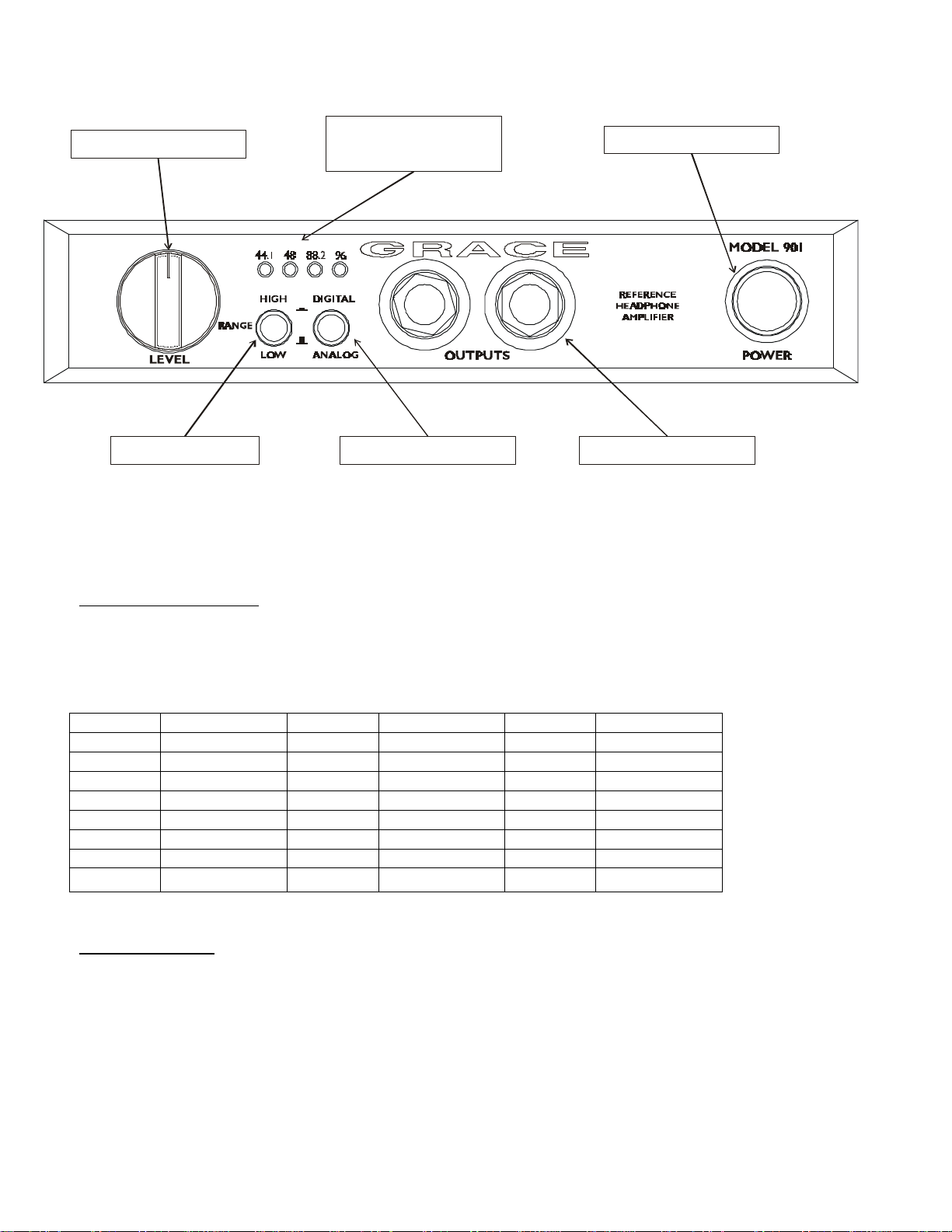
LEVEL CONTROL
INDICATOR
GAIN RANGE INPUT SELECT OUTPUT JACK
SAMPLE RATE
FRONT PANEL CONTROLS
POWER SWITCH
LEVEL CONTROL The 901 level control is assembled with an ultra precision
24 position gold contact switch. Using low inductance surface mount metal
film resistors this switch is the ultimate attenuator for sonic fidelity and level
accuracy. Left-right channel balance is maintained to within 0.05dB at any
setting. The attenuation curve is shown in the table below.
POSITION ATTENUATION POSITION ATTENUATION POSITION ATTENUATION
24 0 16 -16 8 -32
23 -2 15 -18 7 -34
22 -4 14 -20 6 -38
21 -6 13 -22 5 -42
20 -8 12 -24 4 -46
19 -10 11 -26 3 -50
18 -12 10 -28 2 -60
17 -14 9 -30 1
-∞
GAIN RANGE The gain range switch provides an extra 10dB of gain for
monitoring –10dB signals or use with low sensitivity headphones. With the
LEVEL CONTROL at maximum, the LOW gain position provides +10dB overall
gain when using the analog inputs. When using the digital input, this setting
will yield +20dBu out at 0dBFS. When the GAIN RANGE switch is depressed
the overall gain is +20dB
2
Page 4

INPUT SELECT This switch selects the input source. With the switch out the
analog inputs are selected. XLR balanced and RCA unbalanced connectors
are provided on the rear panel. When the INPUT SELECT switch is depressed
the digital inputs are selected. AES3, S/PDIF and optical inputs are provided
on the rear panel. A toggle switch on the rear panel selects between the AES
and S/PDIF-optical inputs.
SAMPLE RATE INDICATORS The LED sample rate indicators display the
digital input signal sample rate. The sample rate is determined by a frequency
comparator, not by the sample rate bits in the digital data. This ensures that
the proper DAC filter settings are used even if there are erroneous sample rate
bits in the signal. Sample rates of 44.1, 48, 88.2 and 96kHz are directly
indicated. 32kHz is indicated when the 44.1 and 96 LEDs are both illuminated.
OUTPUT JACK The two output jacks are wired in parallel so that two sets of
headphones can be used simultaneously. They are wired left channel to the
tip, right channel to the ring and ground to the sleeve.
POWER SWITCH The power switch connects power from the AC input
module to the preamplifier circuitry. When depressed, the POWER SWITCH
will illuminate.
3
Page 5

REAR PANEL CONTROLS
AC INLET The 901 accommodates a standard IEC power cable. The IEC inlet
contains a built in RFI filter.
LINE VOLTAGE SELECTOR To change the line voltage use a small screwdriver to pry
open the voltage select door. Carefully remove the voltage select cam and insert with the
desired voltage showing. Use the table below for voltage settings and fuse values.
CAM SETTING LINE VOLTAGE FUSE VALUE
110Vac 100Vac 120Vac .25A SLOW
220Vac 220Vac 230Vac 240Vac .125A SLOW
WARNING: The Model 901 is capable of delivering over .5 Amperes of
current to the headphone jack. The nature of the TRS jack allows for the ring
to be shorted to the sleeve when the plug is partially inserted. If the plug is
left partially inserted and there is a high amplitude signal on the output of the
amplifier the line fuse will blow. Always replace the line fuse with the proper
type fuse or damage to the amplifier can occur. Note that this fault condition
will not harm your headphones.
DIGITAL IN SELECTOR The digital input selector switch selects either AES or S/PDIF and
optical signals. When the switch is set in the S/PDIF/optical position either input can be
used but only one can be used at a time.
4
Page 6

ANALOG INPUTS The 901 provides both balanced and unbalanced inputs. Input
connections are made using the female XLR connector on the rear panel. These
connectors are wired with pin 2 positive, pin 3 negative and pin 1 ground. The unbalanced
phono type jacks are wired in parallel with pin 2 of the XLR balanced jacks. Connecting
unbalanced and balanced signals simultaneously is not recommended.
Model 901 Specifications
GAIN
Normal Mode -∞ to +10dB
Boost Mode -∞ to +20dB
FREQUENCY RESPONSE
@ 0dBu out +/- .25dB 22Hz - 120kHz
@ 0dBu out +/- .5dB 12Hz - 260kHz
@ 0dBu out +/-3dB 4Hz - 600kHz
MAXIMUM OUTPUT LEVEL
@ 1kHz, 50 Ohm load +23dBu (10.9Vrms, 30.8V p-p)
INPUT IMPEDANCE
40K Ohms balanced
20K Ohms unbalanced
OUTPUT IMPEDANCE
5 Ohms
DYNAMIC RANGE
@ 0dB gain, 50 Ohm load 116dB
@ -10dB gain, 50 Ohm load 121dB
CMRR
3.5Vrms in, 10dB gain >75dB
DISTORTION
THD+N
10dB gain, +10dBu out, 50 Ohm load 0.0051%
SMPTE
4:1 10dB gain, +10dBu out, 50 Ohm load <0.012%
ATTENUATOR CHANNEL MATCHING <0.05dB
D\A SPECIFICATIONS
Input sample rate 44.1, 48, 88.2, 96kHz
Input word length 16 to 24 bits
THD+N
44.1kHz, 24bit, 1kHz, +20dBu out 0.0016%
5
Page 7

NOISE FLOOR
0dB gain, 22-22kHz -95dBu
0dB gain, A-weighted -102dBu
POWER REQUIREMENTS
115VAC .16A
230VAC .08A
6
 Loading...