

Page 1
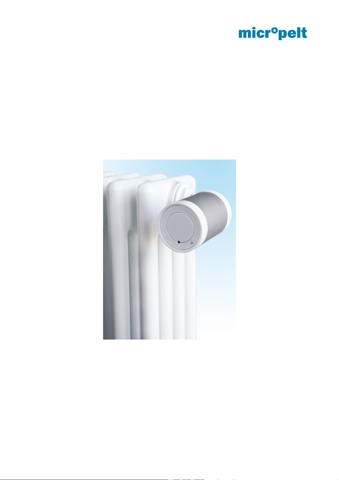
Wireless heating valve actuator
MVA004 EnOcean
User manual and device specification
Annex: List of adapters and theft protection
August 2017 Author: EH4; Germany; Brand: Micropelt - Document number 1DSMVA004_0817v11e
Page 2

MVA004 User manual and device specification
INDEX
INDEX 1
1 Document history 2
2 Use and safety recommendations 3
3 System description 4
4 Energy harvesting 6
5 User Control – Quick overview table 7
5.1 Installation with Manual Pairing 7
5.1 Installation with Remote Commissioning 9
6 Notes on radio operation 10
6.1 Transmission range 10
6.2 Other interference sources 10
6.3 Loss of communication with the room controller 10
7 EEP A5-20-01 description 11
7.1 Protocol Data Overview 11
7.2 Description of individual functions 12
7.2.1 Setpoint Selection (DB1.2, RCU to MVA004) 12
7.2.2 Valve position [%] and Set temperature [°C] in actuator mode (DB3, RCU to MVA004) 12
7.2.3 Summer Mode (DB1.3) 12
7.2.4 Recognition of valve position and reference run 12
7.3 Example of a radio protocol 12
8 EnOcean Remote Management (ReMan), Remote Commissioning (ReCom) 14
8.1 EnOcean Link Table 14
8.2 Outbound Teach-in 14
8.3 ReMan supported functions 14
8.4 ReCom supported standard functions 15
8.5 ReCom supported MVA internal parameter 16
8.6 Dolphin View DO command examples 17
9 Extended features and functions 18
10 Product ID and label 19
11 Performance data 20
12 Mechanical Interface to Radiator Valve 21
13 Annex 1: List of adapters for commonly used non-M30x1,5 valve bodies 22
14 Annex 2: Theft protection 23
August 2017 Page 1 of 23 1DSMVA004_0817v11e
Page 3
MVA004 User manual and device specification
1 Document history
Date Description Version Status
06.04.2017 First release 0817_v2e Released
01.05.2017 Added section 5.5 Remote Commissioning
Added Section 9 and 10
24.05.2017 Minor changes 0817_v4e Released
03.06.2017 Added ReCom commands table 0817_v4e Released
Added DO example descriptions
28.08.2017 DB2.4 BCAP bit linked to DB2.5 Energy Storage 0817_v8e Released
24.11.2017
Safety position: Internal temperature control 21°C
instead of 50% valve position, no change to radio
communication interval
DB2.7…DB2.0 = If RCU Temp. = 0x00 and SPS =
1 (target temperature) then internal temperature
sensor is used
ReCom: Radio interval default = Auto
ReCom: Removed safe mode setting (incl. DO)
ReCom: Removed safe mode com. period (incl.
DO)
0817_v3e Released
0817_v11e Released
August 2017 Page 2 of 23 1DSMVA004_0817v11e
Page 4

MVA004 User manual and device specification
2 Use and safety recommendations
The metallic part of the unit’s housing serves as a heat sink. Be sure that the air circulation around it
is not obstructed by furniture, curtains, plants, or other objects.
If the device has been stored in a cold environment, make sure that it resumes close to room
temperature before use. This is to prevent condensation from forming.
The thermostatic radiator valve is designed for indoor use only. Do not allow the thermostatic radiator
valve to get wet. Its sensitive electronics can be affected.
The unit is best cleaned with a dry or slightly damp cloth. Do not use aggressive cleaning agents or
solvents.
Refrain from exposing the unit to environmental stress such as high mechanical forces (do not step
on it), strong vibrations, direct sunlight or extreme temperatures.
The unit must not be disassembled or modified. In case you are unsure how to use the unit, please
get in touch with your beta test consultant.
Be aware that correct operation can be affected by strong electromagnetic fields. Typical sources of
such are mobile phones, 2-way radios, RC transmitters, microwave ovens, electric motors.
The housing contains actuated springs that can lead to injuries if released. For servicing, refer to
qualified service personnel.
The thermostatic radiator valve has been designed and must solely be used for the purpose of
controlling a M30 x 1.5 heater valve. Any other use may pose a hazard to the device itself, to the
equipment involved, or to the health of the user.
When operating the device in a workplace environment, be sure to observe the workplace regulations
that may apply.
The self-powered thermostatic radiator valve is suitable solely for controlling water-filled heating
radiators. Any other use – including control of floor heating systems - is not permitted and can result
in damage. Do not disassemble or modify any part of the product. It is important to comply with the
safety notice included in these operating instructions.
Read these instructions carefully and keep them for later reference.
Thank you.
August 2017 Page 3 of 23 1DSMVA004_0817v11e
Page 5

MVA004 User manual and device specification
3 System description
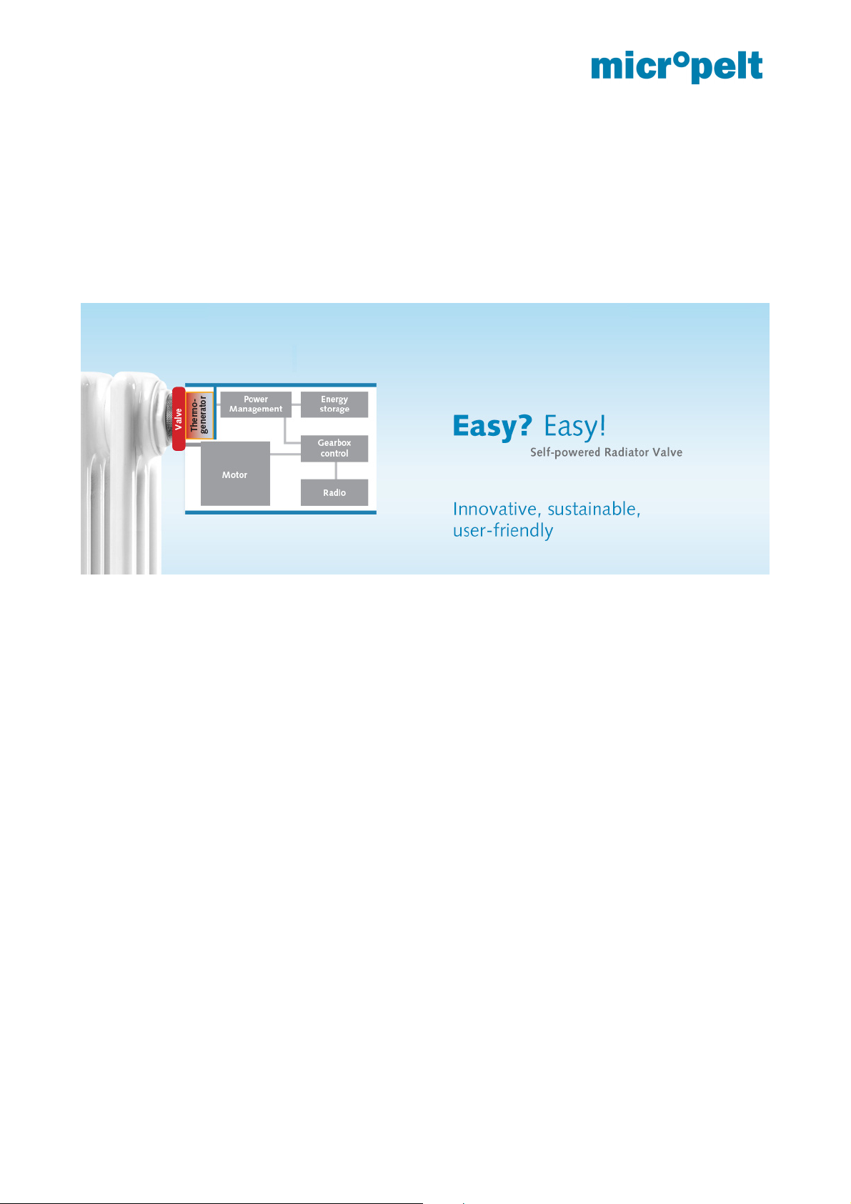
This document defines the properties of Micropelt’s battery free thermostatic radiator valve MVA004. The unit
is directly mounted onto radiator valve bodies (M30x1,5 thread), where it controls the room temperature, based
on signals of a central controller. It is radio-controlled and powered by energy harvesting, so it neither requires
any cabling work nor does it consume batteries. It is designed for maintenance-free operation. The wireless
design makes the unit ideal for retrofit installation and cost-sensitive projects, where cabling cost is prohibitive.
At its heart, the MVA004 contains a thermoelectric harvesting module and integral energy storage. Beyond
this, it contains an electromechanical valve actuator, a radio module and a microcontroller that makes all parts
of the system work together. The actuator is equipped with a number of hard- and software functions that not
only allow remote-management (ReMan) and -commissioning (ReCom) but also features unique status and
monitoring capabilities. The device also offers a debug- and deployment-friendly radio communication interval
of 10 seconds for the first 10 minutes following its initial activation.
At its user interface, MVA004 has a red and a green LED, which are described in more detail in section 4. Two
internal temperature sensors are used with a) its internal temperature controller and freeze protection control
(ambient sensor) and b) the automatic radio duty cycle control of 2, 5 or 10 minutes (flow temperature sensor).
MVA004 is operating with EnOcean standard EEP A5-20-01 (4BS) in either valve position or set
temperature mode. According to the standard protocol, the drive reports to the room controller every 2/5 or 10
minutes (auto radio interval based on flow temperature) and transmits the value of its valve position. The room
controller responds with either a new control value in the value range 0% (valve closed) to 100% (valve
maximum open) or setpoint temperature (0 ... 40 ° C). When the setpoint changes, the actuator motor moves
the motor to the new position.
When operating with the setpoint temperature, it is recommended to use a separate, external room
temperature sensor, which transmits the room temperature to the room controller, which then transmits it to
the drive (as described in A5-20-01 protocol). Without external room temperature, the internal controller uses
the sensor installed in the drive (picture page 5). By heat input from the radiator in the drive, there are
deviations between the measured and actual room temperature, which are compensated by means of an
integrated correction function.
The actuator is in the delivery state in mounting position (motor positon is fully retracted). The actuator has
valve recognition. Unmounted but activated will automatically move the motor back to mounting position and
switch-off the actuator.
The internal energy storage of the actuator is fully charged upon delivery, so that sufficient energy is
available for installation and up to approximately one year of operation. The drive works 365 days a year.
When the heating system is switched on, the actuator then supplies itself independently via the heat of the
heating circuit. Due to the surplus of generated energy in winter, the internal storage provides sufficient energy
for the year-round operation including transition periods and summer.
In the event of a radio failure (6 unsuccessful communication attempts), the internal temperature controller
is activated and the radiator is regulated to a preset 21 ° C. A change of the radio interval does not take place.
The drive goes into normal operation as soon as the radio communication is restored.
When operating in unheated rooms, the internal memory will eventually be discharged. The drive then
moves to the 50% position to recharge the memory. Operation of the drive in unheated rooms is not
recommended
August 2017 Page 4 of 23 1DSMVA004_0817v11e
Page 6
MVA004 User manual and device specification
MVA004 is designed for low power operation. Therefore, all ReMan and ReCom operations are internally
time limited and must be executed within less than 5 seconds. It is strongly recommended to use script
command sets (contact Micropelt for examples) and execute ReMan only for initial teach over the air (Link
Table) and device configuration following its initial deployment.
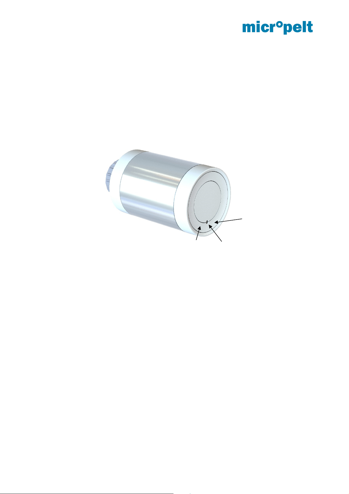
MVA004 has a button lock after one hour function integrated that will prevent from unintended use.
MVA004
Right button
Left button
Temperature sensor
August 2017 Page 5 of 23 1DSMVA004_0817v11e
Page 7
MVA004 User manual and device specification
4 Energy harvesting
The actuator generates the necessary electrical energy for operation by means of a thermoelectric generator
(TEG), which gains electrical energy from the temperature difference between radiator flow and room
temperature. During the heating season, excess energy is accumulated in the internal storage for operation
in transition periods and summer. The energy balance of the actuator is designed to allow operation through
365 days per year when used in typical radiator heating installations.
If, in exceptional cases, the storage voltage drop below a certain limit, the actuator reports this status to the
room controller and takes the protection position (50% valve opening or maintains the set value, whichever is
the higher). Subsequently, the actuator goes to sleep and waits until the memory is re-charged by the
thermoelectric generator back to a sufficient level. As soon as enough energy is available, the actuator
resumes normal operation.
The protection position ensures that the heating valve cannot calcify in an end position and freeze protection
is ensured. Unexpected room temperatures will occur.
August 2017 Page 6 of 23 1DSMVA004_0817v11e
Page 8
MVA004 User manual and device specification
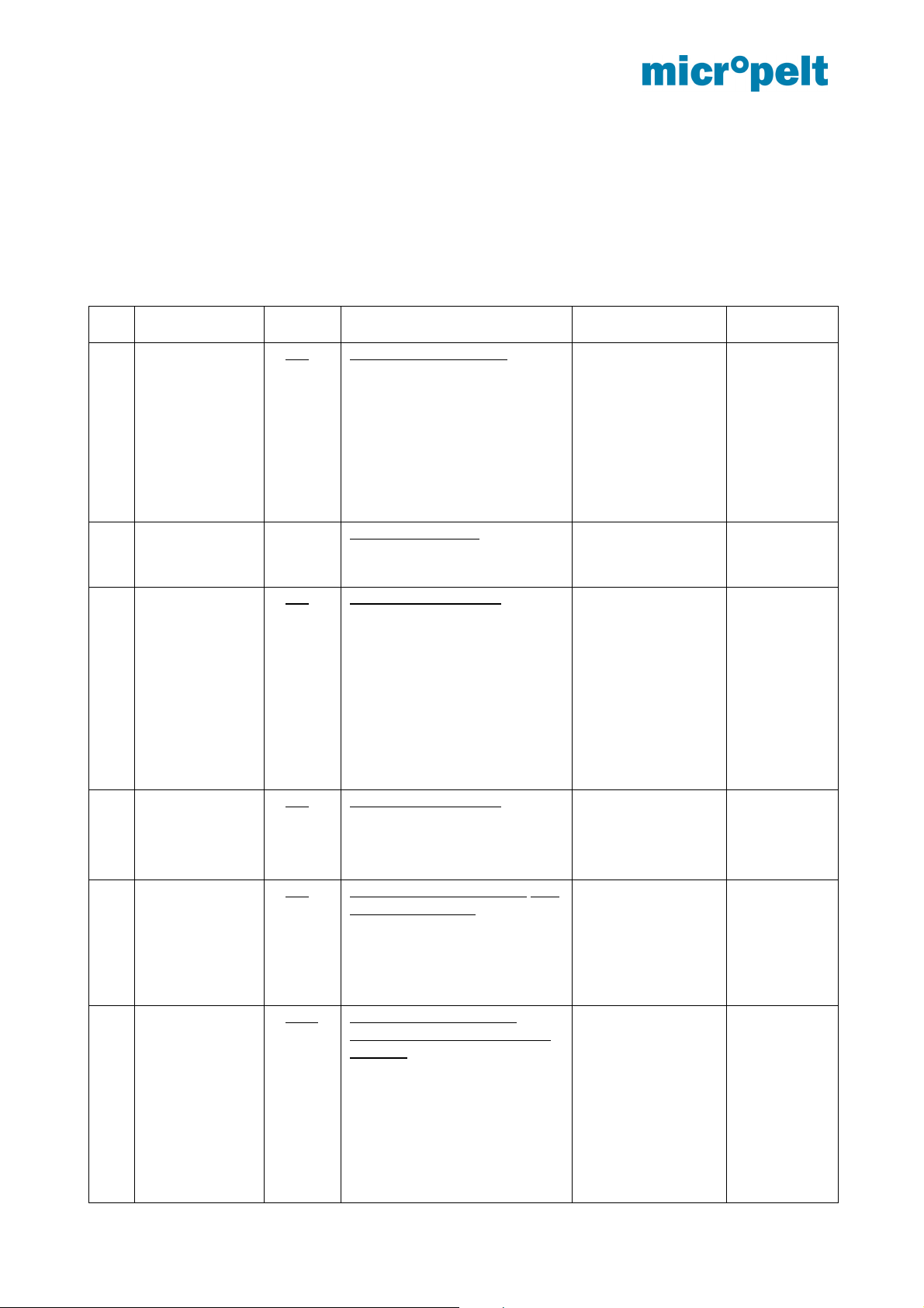
5 User Control – Quick overview table
The below tables provide a quick overview of the product functionality and the installation process.
MORE DETAILED DESCRIPTION IN SECTION 8.
5.1 Installation with Manual Pairing
No Objective Button
No.
1 Pairing from
mounting
position (=
shipping
condition =
OFF)
or normal
operation (while
buttons not
locked)
2 Mounting
1 OR 2 Press for at least 5 sec
Mount the actuator before
Action LED Activity Reasons for
failure
Unit does pairing and remains
in mounting position = shipping
condition = OFF
If unit is not in mounting
position, it moves to mounting
position now.
executing run-in sequence and
normal operation
Success: Single
green flash
Failure: Triple red
flash
Controller or
gateway
either not
present or
not in pairing
mode, so that
pairing fails
3 Run-in
sequence and
normal
operation from
mounting
position
4 Get new target
value (while
buttons not
locked)
5 Return to
mounting
positon
6 Deactivate
button lock
and
RESET
followed by
normal
operation
1 OR 2 Single-press (< 1 sec)
Unit executes run-in sequence;
radio communication occurs
every 10 seconds for 10
minutes, and then reverts to
every 10 minutes.
One hour after this action,
the pushbutton switches will
lock and can only be unlocked,
by performing RESET (5.)
1 OR 2 Single-press (< 1 sec)
Unit immediately gets target
value from controller /
gateway, then moves to the
new target
1 OR 2 Hold button for 5 seconds until
single green flash.
Green LED appears, followed
a triple red LED. The device
will turn the motor back to
mounting position and switch
off.
1 AND 2 Long-press both buttons
simultaneously for at least 10
seconds: The unit enters
normal operation, assuming it
is paired. For 60 min, the unit
will accept a 5-second longpress of any button and for 10
minutes, it will run at a 10second radio communication
interval. It contacts the
Success: Single
green flash
Failure: Triple red
flash
Success: Single
green flash
Failure: Triple red
flash
Success: Single
green flash
followed by triple
red flash
After 10 seconds 1x
green (RESET
activated),
then 2x red (new
start),
after a short break
1x green (normal
operation with
successful
communication)
or
Motor or gear
error
Unit cannot
contact the
controller or
gateway
Unit cannot
contact the
controller or
gateway it
has been
paired with
or unit has
never been
paired.
Mounting or
August 2017 Page 7 of 23 1DSMVA004_0817v11e
Page 9

MVA004 User manual and device specification
controller / gateway
immediately after RESET.
3x red
(communication
error, mounting
error)
motor
problems
August 2017 Page 8 of 23 1DSMVA004_0817v11e
Page 10
MVA004 User manual and device specification
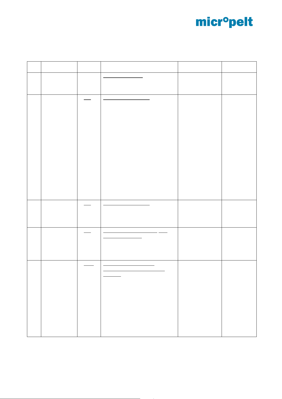
5.1 Installation with Remote Commissioning
No Objective Button
No.
1 Mounting
Mount the actuator before
2 Run-in
sequence and
normal
operation from
mounting
position
1 OR 2 Single-press (< 1 sec)
Action LED Activity Reasons for
executing run-in sequence and
normal operation
Unit executes run-in sequence;
radio communication occurs every
10 seconds for 10 minutes, giving
opportunity for ReMan/ReCom to
configure the unit quickly.
Once 10 minutes have elapsed,
the radio communication interval
defaults to 10 minutes.
One hour after this action, the
pushbutton switches will lock and
can only be unlocked, by
performing RESET
In case of an empty link table
(gateway address), the motor will
move after to its safety position
(Default value = 50%)
3 Get new target
value (while
buttons not
locked)
4 Return to
mounting
positon
5 Deactivate
button lock
and
RESET
followed by
normal
operation
1 OR 2 Single-press (< 1 sec)
Unit immediately gets target value
from controller / gateway, then
moves to the new target
1 OR 2 Hold button for 5 seconds until
single green flash.
Green LED appears, followed a
triple red LED. The device will
turn the motor back to mounting
position and switch off.
1 AND 2 Long-press both buttons
simultaneously for at least 10
seconds: The unit enters normal
operation, assuming it is paired.
For 60 min, the unit will accept a
5-second long-press of any button
and for 10 minutes, it will run at a
10-second radio communication
interval. It contacts the controller /
gateway immediately after
RESET.
failure
Success: Single
green flash
Failure: Triple red
flash
Success: Single
green flash
Failure: Triple red
flash
Success: Single
green flash
followed by triple
red flash
After 10 seconds
1x green (RESET
activated),
then 2x red (new
start), after a
short break 1x
green (normal
operation with
successful
communication)
or 3x red
(communication
error, mounting
error)
Motor or gear
error
Unit cannot
contact the
controller or
gateway
Unit cannot
contact the
controller or
gateway it
has been
paired with
or unit has
never been
paired
Mounting or
motor
problems
August 2017 Page 9 of 23 1DSMVA004_0817v11e
Page 11

MVA004 User manual and device specification
6 Notes on radio operation
6.1 Transmission range
The radio transmission range is limited by both the distance between transmitter and receiver, and by
interference. Indoors, building materials play an important role. Major reflections and signal losses are due to
metallic parts, such as reinforcements in walls and metallized foils, which are used on thermal insulation
products.
Penetration of radio signals:
Material Penetration
Wood, gypsum, uncoated glass 90..100 %
Brick, chipboard 65.. 95 %
Reinforced concrete 10.. 90 %
Metal, aluminum facings 0.. 10 %
For an evaluation of the environment, please see guide values listed below:
Conditions Range / penetration
Line-of-sight Typ 30 m range in passages, up to 100 m in
halls
Plasterboard and wood walls Typ 30 m range through max. 5 walls
Brick and foamed concrete walls Typ 20 m range through max. 3 walls
Reinforced concrete walls & ceilings Typ 10 m range through max. 1 ceiling
Supply blocks and lift shafts should be treated as shields.
In addition, the angle at which the signal enters the wall has to be considered. A shallow angle increases the
effective wall strength as well as the attenuation of the signal. Whenever possible, signals should enter walls
perpendicularly. Alcoves should be circumvented.
For additional information, refer to the EnOcean White Paper “EnOcean Wireless
Systems – Range Planning Guide”.
6.2 Other interference sources
Common sources of interference are devices that generate high-frequency signals. These are typically
computers, audio-/video systems, electronic transformers and ballasts. The distance of the actuator to such
devices should be more than 0.5 m.
6.3 Loss of communication with the room controller
If the actuator cannot establish a dependable radio communication with the room controller, i.e. more than 6
times in sequence the room controller does not receive a radio signal, then the actuator switches to a
reduced radio pattern. The typical 10 minute radio period is extended to one transmission every hour,
reducing the energy consumption while radio contact is interrupted. In addition, the actuator enters the safe
position. Once the radio contact to the room controller recovers, the actuator reverts to requesting
instructions from the controller every 10 minutes.
August 2017 Page 10 of 23 1DSMVA004_0817v11e
Page 12
MVA004 User manual and device specification
7 EEP A5-20-01 description
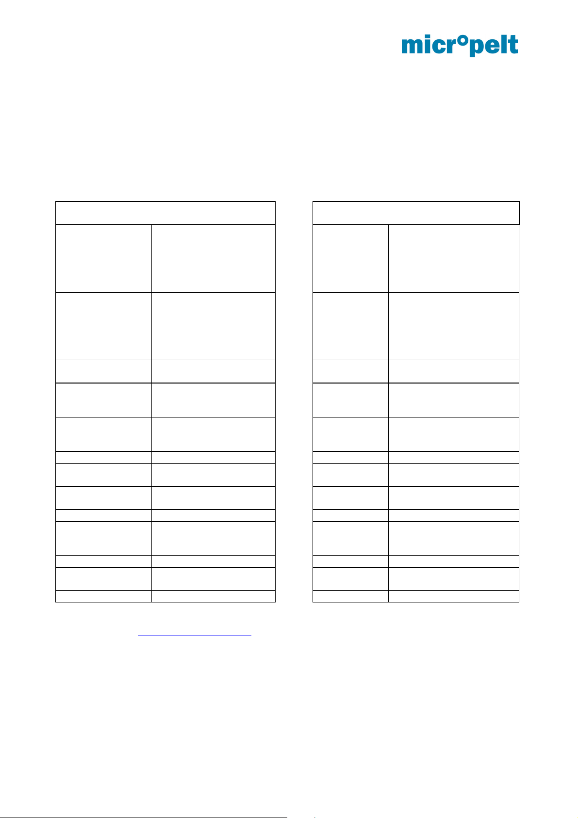
Bidirectional radio communication occurs periodically according to the EnOcean Equipment Profile “EEP A520-01” (Battery Powered Actuator). Communication is triggered by the actuator.
7.1 Protocol Data Overview
Transmit mode from MVA to controller/
gateway/ server
DB3.7…DB3.0 Current valve position
0..100%, linear n=0..100
DB2.7 Not used DB2.7…DB2.0 Room temperature from
DB2.6 Active energy harvesting
(valve is hot)
DB2.5 Energy storage
sufficiently filled
DB2.4 Storage capacity sufficient
(analog DB_2.Bit_5)
DB2.3 Not used DB1.1…DB1.0 Not used (set to “zero”)
DB2.2 Temperature sensor
failure
DB2.1 Not used DB0.3 LRN Bit, defined for data
DB2.0 Motor failure DB0.2…DB0.0 Not used (set to “zero”)
DB1.7…DB1.0 Ambient temperature
MVA
(0…40°C ~ 0x00…0xFF)
DB0.7…DB0.4 Not used
DB0.3 LRN Bit, defined for data
telegram
DB0.2…DB0.0 Not used
More information are available in the latest release version of the published equipment profiles EEP of the
EnOcean Alliance. www.enocean-alliance.org
DB3.7…DB3.0 New valve position
DB1.7....DB1.4 Not used (set to “zero”)
DB1.3 Summer mode,
DB1.2 Setpoint Selection
DB0.7…DB0.4 Not used (set to “zero”)
Receive mode from controller / gateway /
server to MVA
(0...100% ~ 0x00…0x64)
or Target temperature
(0…40°C ~ 0x00…0xFF)
Selection with DB1.2
room sensor
(0…40ºC ~ 0xFF…0x00*)
* for operation with the
internal MVA ambient
sensor must be set to 0x00
transmit / receive time
interval 8 hours
0: Valve pos. (0…100%)
1: Target Temp. (0…40°C)
telegram
August 2017 Page 11 of 23 1DSMVA004_0817v11e
Page 13

MVA004 User manual and device specification
7.2 Description of individual functions
Based on section 7.2
7.2.1 Setpoint Selection (DB1.2, RCU to MVA004)
Selection whether A5-20-01 and the actuator is used with Valve Position (Controller running in the room or
building control system) or with its internal temperature control loop.
7.2.2 Valve position [%] and Set temperature [°C] in actuator mode (DB3, RCU to MVA004)
The external radio partner transmits the temperature setpoint for the internal controller (0 ... + 40°C, DB3.7 ...
DB3.0 = 0 ... 255). The use of a separate, external room temperature sensor is recommended whose room
temperature (DB2.7 ... DB2.0) is transmitted to the drive by the room controller as part of the A5-20-01
protocol. The internal controller thus does not use the ambient temperature measured in the near field of the
radiator, but the actual room temperature.
When operating with an internal temperature sensor, DB2.7 ... DB2.0 must be set to 0x00. Values not
equal to 0x00 are interpreted as sent room temperatures and thus lead to faulty control behavior.
Valve positon (%):The external radio partner transmits a 0 ... 100% control signal (DB3.7 ... DB3.0 = 0 ...
100) and converts it into an actuating movement by the actuator (0% = closed valve / 100% = completely
open valve).
7.2.3 Summer Mode (DB1.3)
When the actuator receives the status message „Summer mode ON“ from the external radio master, then
the valve opens and the transmit/receive interval is increased from 2/5/10 minutes to 8 hours. It is possible to
wake up the iTRV through 1 x pressing the push button. Then the iTRV receives the new setting from the
room controller.
7.2.4 Recognition of valve position and reference run
The valve actuator recognizes during the teach-in the closing position of the valve. During operation the
valve actuator does a full stroke (self-calibration) after every 30 movements, to avoid malfunction of the
valve. It is not intended to trigger the recognition of the valve position via room controller.
7.3 Example of a radio protocol
Radio protocol of valve actuator MVA to server /controller /gateway
Example in HEX "0x32 0x70 0x89 0x08"
DB3.7…DB3.0 = 0x32 = 50: valve position is 50%
DB2.7…DB2.0 = 0x70 includes
o DB2.4 = 1 Energy storage capacity sufficient
o DB2.5 = 1 Energy storage charged
o DB2.6 = 1 Harvesting active
DB1.7…DB1.0 = 0x89 = 137: Internal temperature = 40*DB.1/255 = 40*137/255 = 21,5 °C
August 2017 Page 12 of 23 1DSMVA004_0817v11e
Page 14

MVA004 User manual and device specification
DB0.7…DB0.0 = 0x08: Data telegram
Radio protocol from server /controller /gateway to valve actuator
VALVE POS: Example in HEX "0x05 0x77 0x00 0x08"
DB3.7…DB3.0 = 0x05 = 5: new valve position is 5%
DB2.7…DB2.0 = 0x77 = 119: room temperature = 255 - 119 = 136 => 40 * 136 / 255 = 21,3 °C
DB1.7…DB1.0 = 0x00:
o DB1.3 = 0: regular default radio cycle (no summer mode)
o DB1.2 = 0: DB3.7…DB3.0 is set to valve position %
DB0.7…DB0.0 = 0x08: Data telegram
SET_TEMP: Example in HEX "0x80 0x81 0x04 0x08"
DB3.7…DB3.0 = 0x80 = 128: New target temperature is 40 * 128 / 255 = 20,1°C
DB2.7…DB2.0 = 0x81 = 129: room temperature = 255 - 129 = 126 => 40 * 126 / 255 = 19,8 °C
DB1.7…DB1.0 = 0x04:
o DB1.3 = 0: regular default radio cycle (no summer mode)
o DB1.2 = 1: DB3.7…DB3.0 is set to internal temp.-controller with default duty cycle (Summer
bit not active)
DB0.7…DB0.0 = 0x08: Data telegram
More information are available in the latest release version of the published equipment profiles EEP of the
EnOcean Alliance. www.enocean-alliance.org
August 2017 Page 13 of 23 1DSMVA004_0817v11e
Page 15
MVA004 User manual and device specification
8 EnOcean Remote Management (ReMan), Remote Commissioning (ReCom)
8.1 EnOcean Link Table
MVA004 supports the following number of tech-in relationships:
Inbound EnOcean Link Table: 0 Teach-in relationships (not existing)
Outbound EnOcean Link Table: 3 Tech-in relationships
Comments:
MVA004 uses an outbound link table only, inbound relationships are not supported. Manually erasing the
outbound link table is not possible. Manual pairing (teach-in) however overwrites the first entry of the
outbound link table, clearing the other two entries.
8.2 Outbound Teach-in
Outbound teach-in is supported for EEP A5-20-01 (4BS)
Two options are available to teach-in MVA004 with an external Gateway/Controller:
Manually via teach-in message (4BS version 3)
Using Remote commissioning
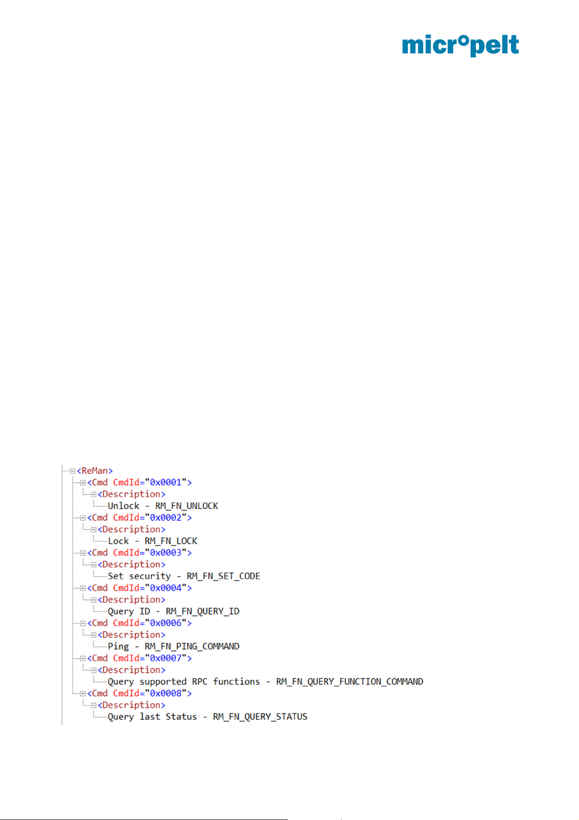
8.3 ReMan supported functions
PING
LOCK, UNLOCK (Default Security ID: 0xFFFFFFFE)
SET CODE
QUERY ID, QUERY STATUS
For further details, pls. refer to the document “Remote Management” by EnOcean GmbH:
https://www.enocean.com/fileadmin/redaktion/pdf/tec_docs/RemoteManagement.pdf
August 2017 Page 14 of 23 1DSMVA004_0817v11e
Page 16
MVA004 User manual and device specification
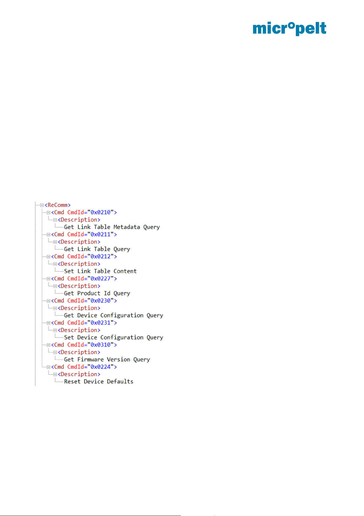
8.4 ReCom supported standard functions
Remote Commissioning Mandatory Commands Bundle:
Remote Commissioning Acknowledge
Get Product ID Query & Response
EnOcean Link Table Basic Commands Bundle
Get Link Table Metadata Query & Response
Get Link Table Query & Response
Set Link Table Content
Configuration Parameters Bundle
Get Device Configuration Query & Response
Set Common Configuration Query
RESET DEVICE DEFAULTS
RESET DEVICE DEFAULTS: MVA will execute reference run and reset all internal parameter to DEFAULT
values (Table 4.5). Link connections and Security Code will not be changed.
August 2017 Page 15 of 23 1DSMVA004_0817v11e
Page 17

MVA004 User manual and device specification
8.5 ReCom supported MVA internal parameter
Parameter INDEX Description
Ambient to target temp offset [K] 0
Radio communication interval
[s/min]
Execute Reference Run 10 0x01
Auto ambient to target offset
parameter
Temp.-control loop gain
parameter
Battery open circuit voltage (V) 13
Please contact Micropelt to receive related xml (DDF) file with further technical details.
1
11 (0x00 … 0xFF) 0 … 255
12 (0x00 … 0xFF) 0 … 255 = 10x GAIN
READ ONLY
(0x00) 0 … Auto* (DEFAULT)
(0x01) 1 … -3 K
(0x02) 2 … -2 K
(0x03) 3 … -1
(0x04) 4 … 0 K
(0x05) 5 … +1 K
(0x06) 6 … +2 K
(0x07) 7 … +3 K
…
(0x0F) 15 … +11 K
(0x00) 0…Auto * (DEFAULT)
(0x01) 1 … 10sec (for debugging only)
(0x02) 2 … 2min
(0x03) 3 … 5min
(0x04) 4 … 10 min
(0x05) 5 … 20min
(0x06) 6 … 30min
* Automatic mode: 2/5/10 minutes interval based flow
temperature and internal storage
DEFAULT 0x00
MVA004 DEFAULT* 44 (0x2C)
* Micropelt Internal parameter
DEFAULT 30 = 0x1E
(0x00 … 0xFF) 0 … 255 = 10x Voltage
Example 0x21 = DEZ 33 : 10 = 3,3Volt
August 2017 Page 16 of 23 1DSMVA004_0817v11e
Page 18
MVA004 User manual and device specification
8.6 Dolphin View DO command examples
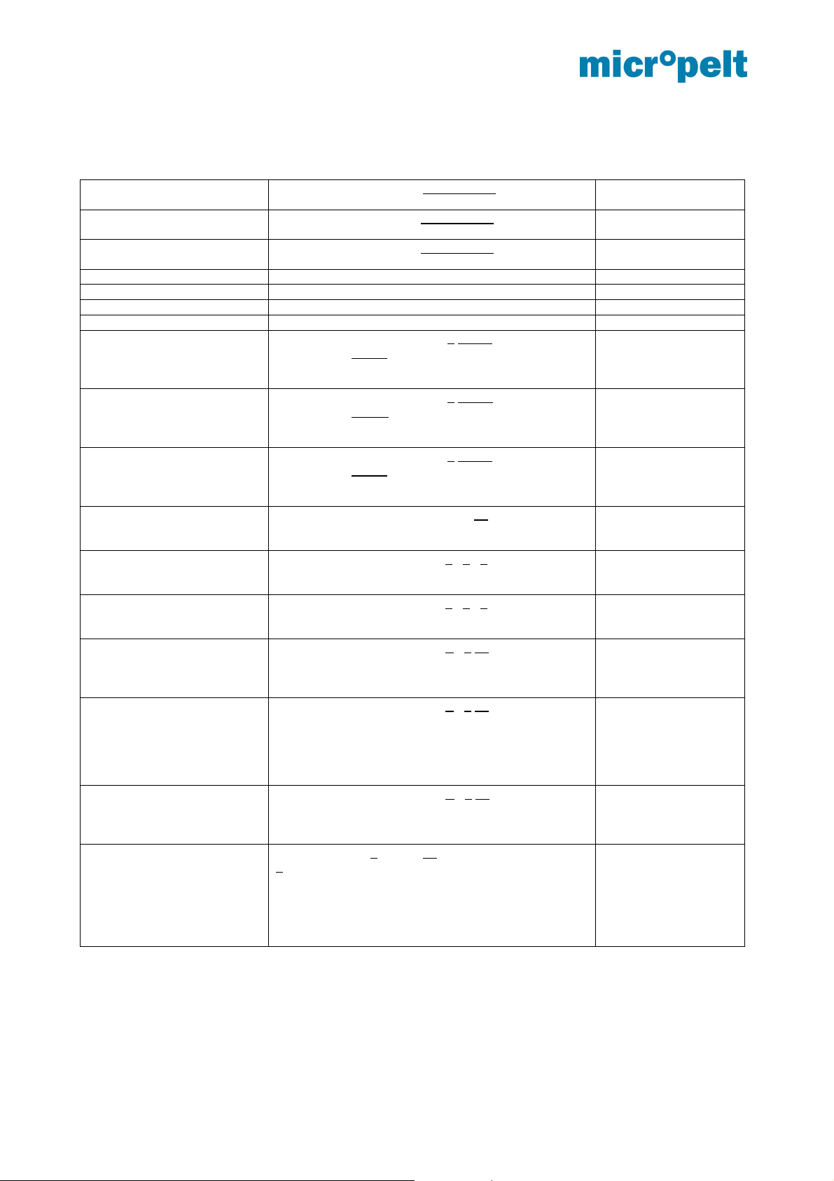
UNLOCK SYS_EX: C0 02 7F F0 01 FF FF FF FE Destination ID Default security-ID:
0xFFFFFFFE
LOCK SYS_EX: 40 02 7F F0 02 FF FF FF FE Destination ID Default security-ID:
0xFFFFFFFE
SET_CODE SYS_EX: 40 02 7F F0 03 FF FF FF FE Destination ID Default security-ID:
0xFFFFFFFE
PING SYS_EX: 40 00 7F F0 06 00 00 00 00 Destination ID
Query_Status SYS_EX: 40 00 7F F0 08 00 00 00 00 Destination ID
Get_Link_Table_Metadata SYS_EX: 40 00 7F F2 10 80 00 02 00 Destination ID
Get All Link Table Data SYS_EX: 40 01 FF F2 11 80 00 02 00 Destination ID
SET_Link_Table_Index 0 SYS_EX: C0 05 7F F2 12 80 00 FF FF Destination ID
SYS_EX: C1 AA FF A5 20 01 00 00 00 Destination ID
Default: 0xFFFFFFF
SET_Link_Table_Index 1 SYS_EX: C0 05 7F F2 12 80 01 FF FE Destination ID
SYS_EX: C1 AE FC A5 20 01 00 00 00 Destination ID
Default: 0xFFFFFFF
SET_Link_Table_Index 2 SYS_EX: C0 05 7F F2 12 80 02 FF FF Destination ID
SYS_EX: C1 AA FF A5 20 01 00 00 00 Destination ID
Default: 0xFFFFFFF
Get_Device_Config SYS_EX: 40 02 FF F2 30 00 00 00 14 Destination ID
SYS_EX: 41 00 00 00 00 00 00 00 00 Destination ID
Set_Device_Config_Index 0
Ambient-to-Target-offset
Set_Device_Config_Index 1
RF-Com-Interval
Set_Device_Config_Index 10
REFERENCE-RUN
Set_Device_Config_Index 11
Offset-a-parameter
Set_Device_Config_Index 12
Temp.-Cntr.-p-parameter
RESET_DEVICE_DEFAULT SYS_EX: 40 00 84 92 24 80 00 00 00 Destination ID
SYS_EX: 40 02 7F F2 31 00 00 01 06 Destination ID
Default: 0x00 (Auto mode)
SYS_EX: 40 02 7F F2 31 00 01 01 04 Destination ID
Default: 0x04 = 10 minutes RF interval
SYS_EX: 40 02 7F F2 31 00 0A 01 00 Destination ID
Default: 0x00
SYS_EX: 40 02 7F F2 31 00 0B 01 00 Destination ID
0 … 255
Default = 0x2C (DEZ44)
MVA004 Default 44
MVA003 Default 75
SYS_EX: 40 02 7F F2 31 00 0C 01 00 Destination ID
0 … 255
Default = 0x1E (DEZ30) => GAIN = 3
84 = Length (required)
1000 0000 = 0x80 Reset device parameter
0110 0000 = 0x60 Reset link tables
1110 0000 = 0xE0 Reset parameter and link tables
0 = Outbound Linktable
Index 0
0xFFFFAAFF = EURID
example
1 = Outbound Linktable
Index 1
0xFFFEAEFC = EURID
example
2 = Outbound Linktable
Index 2
0xFFFFAAFF = EURID
example
Index 0 … 0x14
(20 Parameters)
0 = Index 0
1 = Length
0x06 = Value (+2K)
1 = Index 1
1 = Length
0x04 = Value (10min)
A = Index 10
1 = Length
0x01 = Value (Exec.
Ref.-Run)
B = Index 11
Internal offset
compensation
parameter (a)
C = Index 12
Internal temperature
controller gain (p)
parameter
Reset device to default
values and re-start
10sec for 10min radio
communication interval
August 2017 Page 17 of 23 1DSMVA004_0817v11e
Page 19

MVA004 User manual and device specification
9 Extended features and functions
Micropelt’s newest generation of wireless heating valve actuators integrate and support a number of features
and functions that allow any time and over-the-air status check and monitoring. Internal sensor and
performance data have been stored over a longer time period accessible through a serial data dump.
Unlike the remote commissioning functions listed under 4.5, the following Data logs are accessible on request
only:
Data log readout of battery open-circuit voltage V
Data log readout of harvester open-circuit voltage V
Data log readout ambient temperature °C
Data log readout of flow pipe temperature °C
The above mentioned data log data‘s may not be available in the current MVA004 product release.
Pls. get in touch with Micropelt to get the latest status.
August 2017 Page 18 of 23 1DSMVA004_0817v11e
Page 20
MVA004 User manual and device specification
10 Product ID and label
The MVA004 Product ID consists of the Micropelt manufacturer ID as well as the product reference number.
All functions and properties are available electronically in the shape of the Device Description File (DDF).
Device Manufacturer ID Product Reference
MVA004 Valve Actuator 0x0049 0x00000000
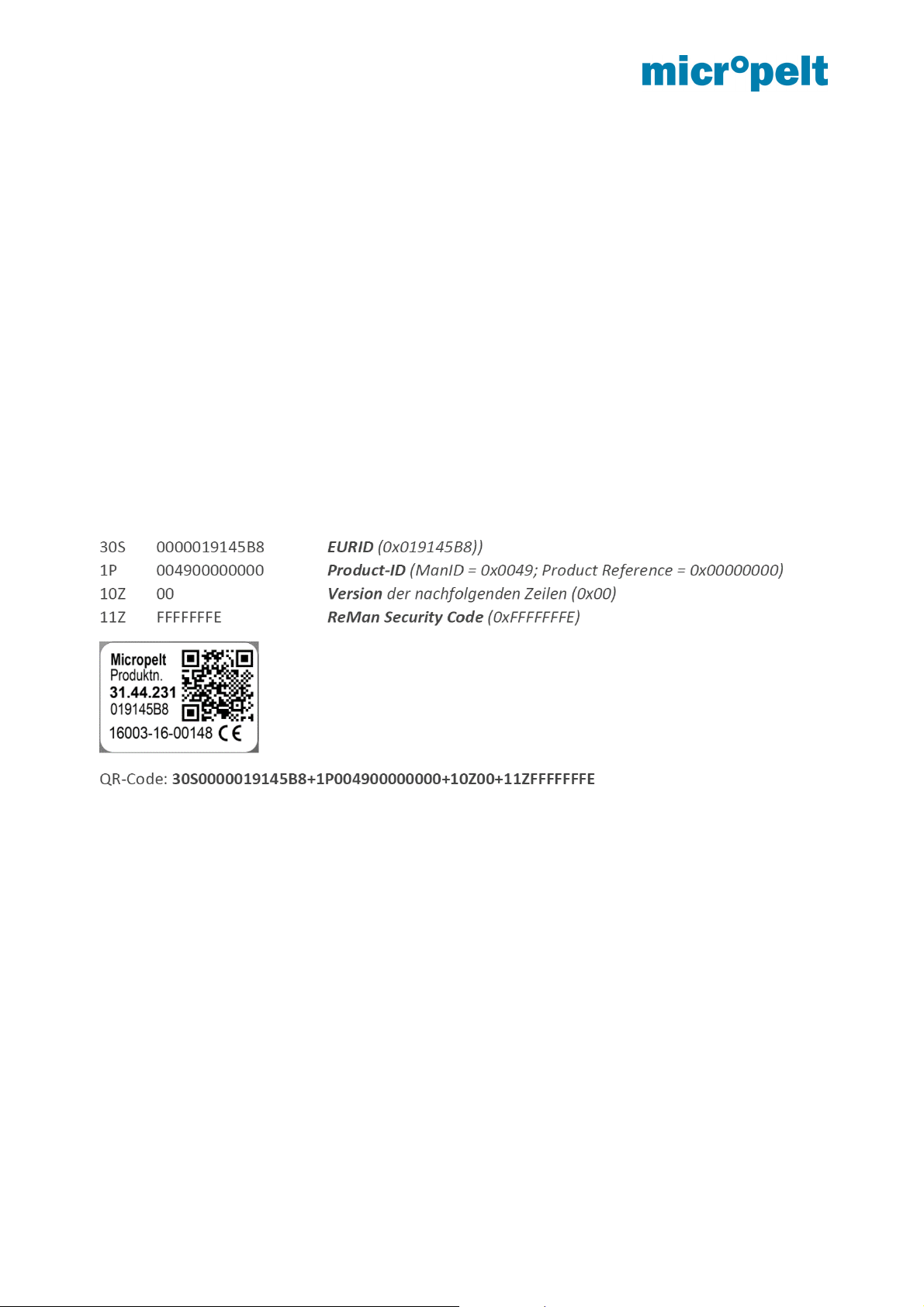
Labeling of each valve actuator is according the EnOcean alliance QR-Code specification, which does include
EURID (EnOcean Unique Radio Identifier) as well as product ID. In addition to such mandatory information,
the label also includes the vendor-specific ReMan Security code, which is fix and internally stored.
The Micropelt MVA004 label does include:
30S EURID_48bit EnOcean Unique Radio Identifier, 6 Byte Hexadecimal
1P 004900000000 ManID = Micropelt, Product Reference = 0x00000000
10Z 00 Header Data Structured Free Text
11Z ReMan_SC_32bit ReMan Security Code, 4 Byte Hexadecimal
August 2017 Page 19 of 23 1DSMVA004_0817v11e
Page 21
MVA004 User manual and device specification
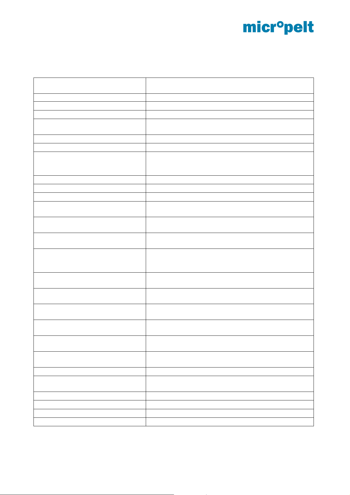
11 Performance data
Parameter
Valve thread M 30 x 1,5 (adapter available for other types)
Ambient operating temperature 0 to 40°C, max 70% rH
Flow pipe temperature 75°C max
Transportation & storage temperature
range
Max pin stroke (calibration range) > 5 mm
Operating pin stroke (0-100 %) 2.5 mm typical
Pin Stroke Resolution (defined by
EnOcean Equipment Profile A5-20-01)
Adjustment speed 0.95 mm/s typical
Stall force 100 N typical
Noise level < 30 dB(A)
RF communication interval Default: Automatic 2/5/10 minutes
Activation and debug
RF communication interval
Antifreeze Below 6ºC, open valve to 95%
Safe position
(following 6 consecutive communication
failures)
EnOcean EEP and operating mode
EnOcean Remote management &
Remote commissioning capability
DDF (Device description file) Yes
Life cycle status and monitoring
capabilities
Accuracy of internal ambient
temperature sensor
Offset of internal ambient temperature
sensor
Energy storage Construed for full year operation
Energy generation minimum
requirement
Radio carrier frequency 868.3 MHz
Maximum radiated power +1.4 dBm (EN 300220-2:V3.1.1)
Receiver Category 2 (EN 300 220-1 V3.1.1)
Conformity CE
-10 to +45°C, max 70% rH
(smallest executable position change has to be 3% from
current physical position)
Other settings through Remote Commissioning
(will revert to the default 10 minutes after 10 minutes)
(referring to operating stroke)
Internal temperature controller with 21°C target value
Will revert to standard operation as soon as radio
communication is online again
(Valve Position and SetTemp)
Default: Automatic offset correction
Fixed offset settings through Remote Commissioning
90 standard heating days with > 45ºC flow pipe temperature
Range
Steps of 1%
~ 10 sec
A5-20-01
Yes
(Section 8)
(Section 8)
Yes
(Section 9)
+/- 0.5 ºC
August 2017 Page 20 of 23 1DSMVA004_0817v11e
Page 22
MVA004 User manual and device specification
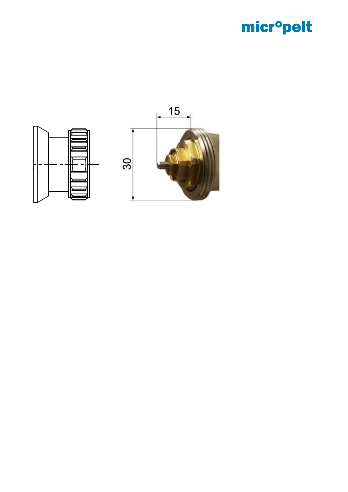
12 Mechanical Interface to Radiator Valve
The MVA004 is designed to mount directly onto an M30 x 1.5mm radiator valve body.
Several other valve types are supported by metallic adapter pieces.
August 2017 Page 21 of 23 1DSMVA004_0817v11e
Page 23
MVA004 User manual and device specification
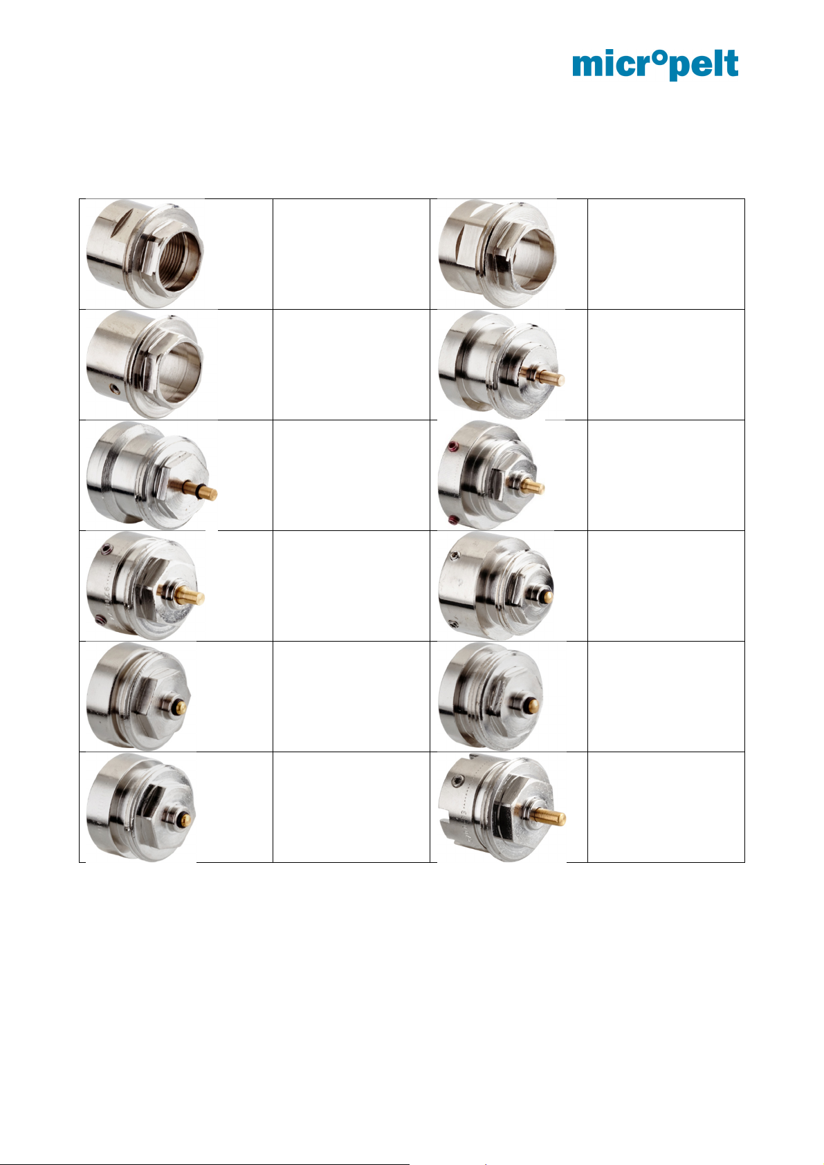
13 Annex 1: List of adapters for commonly used non-M30x1,5 valve bodies
Danfoss Series 2
(M20 x 1.0)
Item no. 9703-24.700
Danfoss Series 3
(M23.5 x 1.5)
Item no. 9704-24.700
Danfoss RA2000
Item no. 9702-24.700
Adapter Comap
(M28 x 1.5)
Item no. 9700-55.700
Danfoss RAV-L
(26 mm)
Item no. 9700-24.700
Adapter TA
(M28 x 1.5)
Item no. 9701-28.700
Adapter Oventrop
(M30 x 1.0)
Item no. 9700-10.700
Danfoss RAV
Item no. 9800-24.700
Adapter Vaillant
( 30 mm)
Item no. 9700-27.700
Adapter Herz
(M28 x 1.5)
Item no. 9700-30.700
August 2017 Page 22 of 23 1DSMVA004_0817v11e
Adapter Markaryd
(M28 x 1.5)
Art-No. 9700-41.700
Adapter Giacomini
(ca. 22.6 mm)
Item no. 9700-33.700
Page 24
MVA004 User manual and device specification
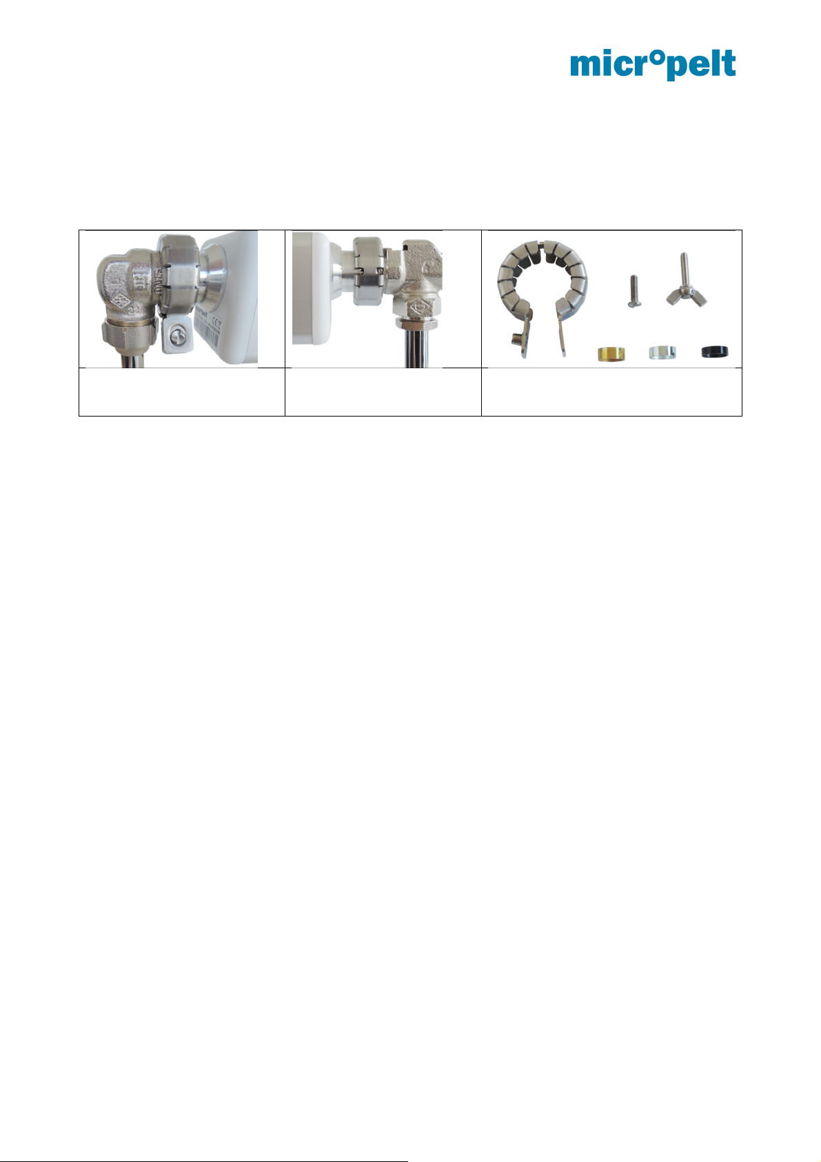
14 Annex 2: Theft protection
Pls. contact Micropelt to receive more information about MVA‐DS01 theft protection solution.
Stainless steel clamp with distance
rings and security screw (requires
special tool to open)
August 2017 Page 23 of 23 1DSMVA004_0817v11e
 Loading...