

Page 1
Wireless heating valve actuator
MVA003 EnOcean
User manual and device specification
Annex: List of adapters and theft protection
Preliminary
May 2017 Author: EH4; Germany / Brand Micropelt - Document number 1DSMVA003_0217v7e
Page 2

MVA003 User manual and device specification
INDEX
INDEX 1
1 Introduction 2
2 User Control – Quick overview table 3
2.1 Installation with Manual Pairing 3
2.2 Installation with Remote Commissioning 5
3 Notes on radio operation 6
3.1 Transmission range 6
3.2 Other interference sources 6
3.3 Loss of communication with the room controller 6
4 EEP A5-20-01 description 7
4.1 Protocol Data Overview 7
4.2 Description of individual functions 7
4.3 Example of a radio protocol 8
5 EnOcean Remote Management (ReMan), Remote Commissioning (ReCom) 9
5.1 EnOcean Link Table 9
5.2 Outbound Teach-in 9
5.3 ReMan supported functions 9
5.4 ReCom supported standard functions 10
5.5 ReCom supported MVA internal parameter 11
5.6 Dolphin View DO command examples 12
6 Extended features and functions 13
7 User Control description 14
7.1 Installation with Manual Pairing 14
7.2 Installation with Remote Commissioning 15
8 Product ID and label 16
9 Performance data 17
10 Mechanical Interface to Radiator Valve 18
11 Annex 1: List of adapters for commonly used non-M30x1,5 valve bodies 19
12 Annex 2: Theft protection 20
Preliminary
May 2017 Page 1 of 20 1DSMVA003_0217v7e
Page 3
MVA003 User manual and device specification
1 Introduction
This document defines the properties of Micropelt’s battery free thermostatic radiator valve MVA003. The unit
is directly mounted onto the radiator valves, where it controls the room temperature, based on signals of a
central controller. It is radio-controlled and powered by energy harvesting, so it neither requires any cabling
work nor does it consume batteries. It is designed for maintenance-free operation. The wi reless design ma kes
the unit ideal for retrofit installation and cost-sensitive projects, where cabling cost is prohibitive.
At its heart, the MVA003 contains a thermoelectric harvesting module and integral energy storage. The internal
storage is charged throughout the heating season from surplus energy produced by the harvesting element.
This allows the actuator to operate 365 day/year. Beyond this, it contains an electromechanical valve actuator,
a radio module and a microcontroller that makes all parts of the system work together. The actuator is equipped
with a number of hard- and software functions that not only allow remote-management (ReMan) and commissioning (ReCom) but also features unique status and monitoring capabilities. The device also offers a
debug- and deployment-friendly radio communication interval of 10 seconds for the first 10 minutes following
its initial activation.
MVA003 is operating with EnOcean standard EEP A5-20-01 (4BS) valve position or set temperature.
MVA003 is designed for low power operation. Therefore, all ReMan and ReCom operations are internally
time limited and must be executed within less than 5 seconds. It is strongly recommended to use script
command sets (contact Micropelt for examples) and execute ReMan only for initial teach over the air (Link
Table) and device configuration following its initial deployment.
MVA003 has a button lock after one hour function integrated that will prevent from unintended use.
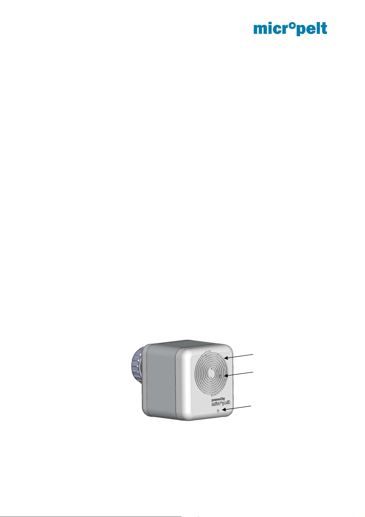
The unit’s user interface consists of one user button and one LED. An ambient temperature sensor serves
both the temperature control and the antifreeze function. The actuator fits a standard radiator valve M30 x 1.5
mm.
MVA003
LED (below cover)
Button
Ambient temperature
sensor
Preliminary
May 2017 Page 2 of 20 1DSMVA003_0217v7e
Page 4
MVA003 User manual and device specification
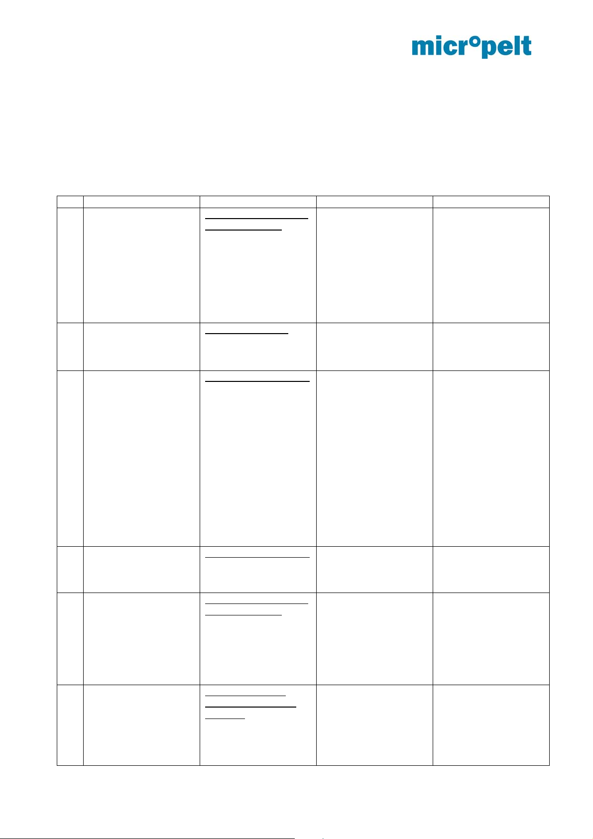
2 User Control – Quick overview table
The below tables provide a quick overview of the product functionality and the installation process.
MORE DETAILED DESCRIPTION IN SECTION 8.
2.1 Installation with Manual Pairing
No Objective Action LED Activity Reasons for failure
1) Pairing from mounting
position (= shipping
condition = OFF)
or normal operation
(while buttons not
locked)
2) Mounting
3) Run-in sequence and
normal operation from
mounting position
Press pushbutton twice
within 2 seconds.
Unit sends pairing
request and remains in
mounting position =
shipping condition =
OFF
If unit is not in mounting
position, it moves to
mounting position now.
Mount the actuator
before executing run-in
sequence and normal
operation
Press pushbutton once.
Unit executes run-in
sequence,
radio communication
occurs once every 10
seconds for the
duration of 10 minutes,
then relaxes to once
every 10 minutes.
Success: Single red
flash
Failure: 6x red flash
Success: Radio
communication
Failure: 3x red flash,
unit returns to mounting
position = OFF
Controller or gateway
either not present or
not in pairing mode, so
that pairing fails
Unit is not attached to
an appropriate valve,
an inadequate adapter
is being used,
motor or gear error,
unit is not paired,
unit cannot contact the
controller
4) Get new target value
(while buttons not
locked)
5) Return to mounting
positon
6) RESET
from normal operation
One hour after this
action, the pushbutton
switch will lock and can
only be unlocked, by
performing RESET
Press pushbutton once.
Unit requests new
settings from controller
or gateway
Press pushbutton twice
within 2 seconds.
Unit moves the plunger
fully in and sets inner
stop reference anew,
then turns off,
remaining in mounting
position
Push and hold the
button for at least 10
seconds:
Unit moves to 50%,
resets, awakes, moves
the plunger fully in,
does the run-in
Success: Single red
flash
Failure: 3x red flash
3x red flash, unit
returns to mounting
position = OFF
After 10 sec have
elapsed and RESET is
triggered:
Single red flash
For run-in sequence,
see item (3)
Unit is not paired, unit
cannot contact the
controller
User failed to press the
pushbutton long
enough
Preliminary
May 2017 Page 3 of 20 1DSMVA003_0217v7e
Page 5

MVA003 User manual and device specification
sequence and enters
normal operation.
It assumes it is paired.
For 10 minutes, it runs
at a 10 second radio
communication interval.
7) RESET
from mounting position
Push and hold the
button for at least 10
seconds:
Unit moves the plunger
fully in and sets inner
stop reference anew,
then turns off,
remaining in mounting
position
After 10 sec have
elapsed and RESET is
triggered:
Single red flash
User failed to press the
pushbutton long
enough
Preliminary
May 2017 Page 4 of 20 1DSMVA003_0217v7e
Page 6

MVA003 User manual and device specification
2.2 Installation with Remote Commissioning
Objective Action LED Activity Reasons for
failure
1) Mounting
2) Run-in sequence
and normal
operation from
mounting position
3) Get new target
value
4) Return to
mounting positon
5) RESET followed
by normal
operation
Pls. mount the actuator before
executing run-in sequence and
normal operation
Single-press push-button (< 1
sec)
Unit executes run-in sequence,
radio communication occurs
every 10 seconds for 10 minutes,
giving opportunity for Remote
Commissioning to configure the
unit quickly.
Once 10 minutes have elapsed,
the radio communication interval
defaults to 10 minutes.
Single-press push-button (< 1
sec)
Unit immediately gets target
value from controller / gateway,
then moves to the new target
Press pushbutton twice within 2
seconds.
Unit moves the plunger fully in
and sets inner stop reference
anew, then turns off, remaining in
mounting position
Long-press push-button for at
least 10 seconds:
The unit enters normal operation,
assuming it is paired.
For 60 min, the unit will accept a
5-second long-press of any
button and for 10 minutes, it will
run at a 10-second radio
communication interval.
It contacts the controller /
gateway immediately after
RESET.
Success: Single red
flash
Failure: 6x red flash
Success: Single red
flash
Failure: 3x red flash
Success: 3x red
flash, unit returns to
mounting position =
OFF
Success: Single red
flash
Failure: 3x red flash
Motor or gear error
Unit cannot contact
the controller or
gateway
Unit cannot contact
the controller or
gateway it has been
paired with
or unit has never
been paired
Preliminary
May 2017 Page 5 of 20 1DSMVA003_0217v7e
Page 7

MVA003 User manual and device specification
3 Notes on radio operation
3.1 Transmission range
The radio transmission range is limited by both the distance between transmitter and receive r, and by
interference. Indoors, building materials play an important role. Major reflections and si gnal losses are due to
metallic parts, such as reinforcements in walls and metallized foils, which are used on thermal insulation
products.
Penetration of radio signals:
Material Penetration
Wood, gypsum, uncoated glass 90..100 %
Brick, chipboard 65.. 95 %
Reinforced concrete 10.. 90 %
Metal, aluminum facings 0.. 10 %
For an evaluation of the environment, please see guide values listed below:
Conditions Range / penetration
Line-of-sight Typ 30 m range in passages, up to 100 m in
halls
Plasterboard and wood walls Typ 30 m range through max. 5 walls
Brick and foamed concrete walls Typ 20 m range through max. 3 walls
Reinforced concrete walls & ceilings Typ 10 m range through max. 1 ceiling
Supply blocks and lift shafts should be treated as shields.
In addition, the angle at which the signal enters the wall has to be considered. A shallow angle increases the
effective wall strength as well as the attenuation of the signal. Whenever possible, signals should enter walls
perpendicularly. Alcoves should be circumvented.
For additional information, refer to the EnOcean White Paper “EnOcean Wireless
Systems – Range Planning Guide”.
3.2 Other interference sources
Common sources of interference are devices that generate high-frequency signals. These are typically
computers, audio-/video systems, electronic transformers and ballasts. The distance of the actuator to such
devices should be more than 0.5 m.
3.3 Loss of communication with the room controller
If the actuator cannot establish a dependable radio communication with the room controller, i.e . more than 6
times in sequence the room controller does not receive a radio signal, then the actuator switches to a
reduced radio pattern. The typical 10 minute radio period is extended to one transmission every hour,
reducing the energy consumption while radio contact is interrupted. In addition, the actuator enters the safe
position. Once the radio contact to the room controller recovers, the actuator reverts to requesting
instructions from the controller every 10 minutes.
Preliminary
May 2017 Page 6 of 20 1DSMVA003_0217v7e
Page 8

MVA003 User manual and device specification
4 EEP A5-20-01 description
Bidirectional radio communication occurs periodically according to the EnOcean Equipment Profile “EEP A520-01” (Battery Powered Actuator). Communication is triggered by the actuator.
4.1 Protocol Data Overview
Transmit mode from MVA to controller/
gateway/ server
DB_3 Current valve position
0..100%, linear n=0..100
DB_2.Bit_7 Not used DB_2 Room temperature from
DB_2.Bit_6 Active energy harvesting
(valve is hot)
DB_2.Bit_5 Energy storage
sufficiently charged
DB_2.Bit_4-0 Storage capacity DB_1.Bit_2-0 Setpoint Selection
DB_1 Internal temperature of
MVA
DB_0.Bit_7-4 Not used DB_0.Bit_3 LRN Bit, defined for data
DB_0.Bit_3 LRN Bit, defined for data
telegram
DB_0.Bit_2-0 Not used
DB_3 New valve position
DB_1.Bit_7-4 Not used
DB_1.Bit_3 Summer mode,
DB_0.Bit_7-4 Not used
DB_0.Bit_2-0 Not used
Receive mode from controller / gateway
/ server to MVA
0..100% linear or Target
temperature (0…40°C)
Selection with
DB_1.Bit_2-0)
room sensor
transmit / receive time
interval 8 hours
0: Valve position
(0…100%)
1: Target Temp.
(0…40°C)
telegram
4.2 Description of individual functions
Setpoint Selection
Selection whether A5-20-01 and the actuator is used with Valve Position (Controller running in the room or
building control system) or with its internal temperature control loop.
Valve position / Set temperature in actuator mode (DB_3)
Based on 4.2.1:
Target temperature (°C): The room control unit transmits a target temperature between 0°C and +40° C
which will be used as by the internal control loop to calculate valve positions.
It is recommended to also transmit the RCU temperature used to operate the MVA internal control loop
(p-controller with GAIN).
Valve positon (%): From the external radio master a control value of 0..100% is transmitted and the valve
actuator executes a valve movement (0% = valve closed / 100% = valve open).
Preliminary
May 2017 Page 7 of 20 1DSMVA003_0217v7e
Page 9

MVA003 User manual and device specification
Summer Mode (DB_1.Bit_3)
When the actuator receives the status message „Summer mode ON“ from the external radio master, then
the valve opens and the transmit/receive interval is increased from 10 minutes to 8 hours. It is possible to
wake up the iTRV through 1 x pressing the push button. Then the iTRV receives the new setting from the
room controller.
Recognition of valve position
The valve actuator recognizes during the teach-in the closing position of the valve. During ope ration the
valve actuator does a full stroke (self-calibration) after every 30 movements, to avoid malfunction of the
valve. It is not intended to trigger the recognition of the valve position via room controller.
4.3 Example of a radio protocol
Radio protocol of valve actuator MVA to server /controller /gateway
Example in HEX "0x32 0x60 0x89 0x08"
DB.3 = 0x32 = 50: valve position is 50%
DB.2 = 0x60: DB2.Bit_5 = 1 (Energy storage charged) / DB2.Bit_6 = 1 (Harvesting active)
DB.1 = 0x89 = 137: Internal temperature = 40*DB.1/255 = 40*137/255 = 21,5 °C
DB.0 = 0x08: Data telegram
Radio protocol from server /controller /gateway to valve actuator
VALVE POS: Example in HEX "0x05 0x81 0x00 0x08"
DB.3 = 0x05 = 5: new valve position is 5%
DB.2 0x77 = 119: room temperature = 255 - 119 = 136 = 40*136/255 = 21,3 °C
DB.1 = 0x00: DB_1.Bit_3 = 0: regular radio cycle 10 Minutes (no summer mode)
DB.0 = 0x08: Data telegram
SET_TEMP: Example in HEX "0x80 0x81 0x04 0x08"
DB.3 = 0x80 = 128: New target temperature is 20,1°C
DB.2 0x77 = 119: room temperature = 255 - 119 = 136 = 40*136/255 = 21,3 °C
DB.1 = 0x04: DB_1.Bit_3 = 0: Internal Temp.-controller with 10min Duty Cycle (Summer bit not
active)
DB.0 = 0x08: Data telegram
Preliminary
May 2017 Page 8 of 20 1DSMVA003_0217v7e
Page 10

MVA003 User manual and device specification
5 EnOcean Remote Management (ReMan), Remote Commissioning (ReCom)
5.1 EnOcean Link Table
MVA003 supports the following number of tech-in relationships:
Inbound EnOcean Link Table: 0 Teach-in relationships (not existing)
Outbound EnOcean Link Table: 3 Tech-in relationships
Comments:
MVA003 uses an outbound link table only, inbound relationships are not supported. Manually erasing the
outbound link table is not possible. Manual pairing (teach-in) however overwrites the first entry of the
outbound link table, clearing the other two entries.
5.2 Outbound Teach-in
Outbound tech-in is supported for EEP A5-20-01.
Two options are available to tech-in MVA with an external Gateway/Controller:
Manual via Teach-in message (4BS version 3)
Using Remote commissioning
5.3 ReMan supported functions
PING
LOCK, UNLOCK (Default Security ID: 0xFFFFFFFE)
SET CODE
QUERY ID, QUERY STATUS
For further details, pls. refer to Remote Management EnOcean GmbH
https://www.enocean.com/fileadmin/redaktion/pdf/tec_docs/RemoteManagement.pdf
Preliminary
May 2017 Page 9 of 20 1DSMVA003_0217v7e
Page 11

MVA003 User manual and device specification
5.4 ReCom supported standard functions
Remote Commissioning Mandatory Commands Bundle:
Remote Commissioning Acknowledge
Get Product ID Query & Response
EnOcean Link Table Basic Commands Bundle
Get Link Table Metadata Query & Response
Get Link Table Query & Response
Set Link Table Content
Configuration Parameters Bundle
Get Device Configuration Query & Response
Set Common Configuration Query
RESET DEVICE DEFAULTS
RESET DEVICE DEFAULTS: MVA will execute reference run and reset all internal parameter to DEFAULT
values (Table 4.5). Link connections and Security Code will not be changed.
Preliminary
May 2017 Page 10 of 20 1DSMVA003_0217v7e
Page 12

MVA003 User manual and device specification
5.5 ReCom supported MVA internal parameter
Parameter INDEX Description
Ambient to target temp offset [K] 0
Radio communication interval
[s/min]
Safe mode setting [%] 2 (0x00 … 0x64) 0 … 100%
Safe mode communication
period [h]
Execute Reference Run 10 0x01
Auto ambient to target offset
parameter
Temp.-control loop gain
parameter
Battery open circuit voltage (V) 13
Please contact Micropelt to receive related xml (DDF) file with further technical details.
1 (0x00) 0…Auto *
5 (0x00) 0 … 0,5h
11 (0x00 … 0xFF) 0 … 255
12 (0x00 … 0xFF) 0 … 255 and multiply with 10
READ ONLY
(0x00) 0 … Auto* (DEFAULT)
(0x01) 1 … -3 K
(0x02) 2 … -2 K
(0x03) 3 … -1
(0x04) 4 … 0 K
(0x05) 5 … +1 K
(0x06) 6 … +2 K
(0x07) 7 … +3 K
…
(0x0F) 15 … +11 K
(0x01) 1 … 10sec (for debugging only)
(0x02) 2 … 2min
(0x03) 3 … 5min
(0x04) 4 … 10 min (DEFAULT)
(0x05) 5 … 20min
(0x06) 6 … 30min
* Automatic mode: 2/5/10 minutes interval based flow
temperature and internal storage
DEFAULT 50% (0x32)
(0x01) 1 … 1h (DEFAULT)
(0x02) 2 … 2h
(0x03) 3 … 4h
(0x04) 4 … 8h
(0x05) 5 … 24h
(0x06) 6 … 48h
(0x07) 7 … 96h
DEFAULT 0x00
MVA003 DEFAULT 75* (0x4B)
* Micropelt Internal parameter
DEFAULT 3 (0x1E)
(0x00 … 0xFF) 0 … 255 and divide by 10
Example 0x21 = DEZ 33 : 10 = 3,3Volt
Preliminary
May 2017 Page 11 of 20 1DSMVA003_0217v7e
Page 13

MVA003 User manual and device specification
5.6 Dolphin View DO command examples
UNLOCK SYS_EX: C0 02 7F F0 01 FF FF FF FE Destination ID Default security-ID:
0xFFFFFFFE
LOCK SYS_EX: 40 02 7F F0 02 FF FF FF FE Destination ID Default security-ID:
0xFFFFFFFE
SET_CODE SYS_EX: 40 02 7F F0 03 FF FF FF FE Destination ID Default security-ID:
0xFFFFFFFE
PING SYS_EX: 40 00 7F F0 06 00 00 00 00 Destination ID
Query_Status SYS_EX: 40 00 7F F0 08 00 00 00 00 Destination ID
Get_Link_Table_Metadata SYS_EX: 40 00 7F F2 10 80 00 02 00 Destination ID
Get All Link Table Data SYS_EX: 40 01 FF F2 11 80 00 02 00 Destination ID
SET_Link_Table_Index 0 SYS_EX: C0 05 7F F2 12 80 00 FF FF Destination ID
SYS_EX: C1 AA FF A5 20 01 00 00 00 Destination ID
Default: 0xFFFFFFF
SET_Link_Table_Index 1 SYS_EX: C0 05 7F F2 12 80 01 FF FE Destination ID
SYS_EX: C1 AE FC A5 20 01 00 00 00 Destination ID
Default: 0xFFFFFFF
SET_Link_Table_Index 2 SYS_EX: C0 05 7F F2 12 80 02 FF FF Destination ID
SYS_EX: C1 AA FF A5 20 01 00 00 00 Destination ID
Default: 0xFFFFFFF
Get_Device_Config SYS_EX: 40 02 FF F2 30 00 00 00 14 Destination ID
SYS_EX: 41 00 00 00 00 00 00 00 00 Destination ID
Set_Device_Config_Index 0
Ambient-to-Target-offset
Set_Device_Config_Index 1
RF-Com-Interval
Set_Device_Config_Index 2
Safe-mode-setting-%
Set_Device_Config_Index 5
Safe-mode-communicationperiod
Set_Device_Config_Index 10
REFERENCE-RUN
Set_Device_Config_Index 11
Offset-a-parameter
Set_Device_Config_Index 12
Temp.-Cntr.-p-parameter
RESET_DEVICE_DEFAULT SYS_EX: 40 00 84 92 24 80 00 00 00 Destination ID
SYS_EX: 40 02 7F F2 31 00 00 01 06 Destination ID
Default: 0x00 (Auto mode)
SYS_EX: 40 02 7F F2 31 00 01 01 04 Destination ID
Default: 0x04 = 10 minutes RF interval
SYS_EX: 40 02 7F F2 31 00 02 01 32 Destination ID
Default: 0x32 (50%)
SYS_EX: 40 02 7F F2 31 00 02 01 01 Destination ID
Default: 0x01 (1 hour RF interval)
SYS_EX: 40 02 7F F2 31 00 0A 01 00 Destination ID
Default: 0x00
SYS_EX: 40 02 7F F2 31 00 0B 01 00 Destination ID
0 … 255
Default = 0x4B (DEZ75)
MVA004 Default 91
MVA003 Default 75
SYS_EX: 40 02 7F F2 31 00 0C 01 00 Destination ID
0 … 255
Default = 0x1E (DEZ30) => GAIN = 3
84 = Length (required)
1000 0000 = 0x80 Reset device parameter
0110 0000 = 0x60 Reset link tables
1110 0000 = 0xE0 Reset parameter and link tables
0 = Outbound Linktable
Index 0
0xFFFFAAFF = EURID
example
1 = Outbound Linktable
Index 1
0xFFFEAEFC = EURID
example
2 = Outbound Linktable
Index 2
0xFFFFAAFF = EURID
example
Index 0 … 0x14
(20 Parameters)
0 = Index 0
1 = Length
0x06 = Value (+2K)
1 = Index 1
1 = Length
0x04 = Value (10min)
2 = Index 2
1 = Length
0x32 = Value (50%)
2 = Index 2
1 = Length
0x01 = Value (1h)
A = Index 10
1 = Length
0x01 = Value (Exec.
Ref.-Run)
B = Index 11
Internal offset
compensation
parameter (a)
C = Index 12
Internal temperature
controller gain (p)
parameter
Reset device to default
values and re-start
10sec for 10min RF
interval
Preliminary
May 2017 Page 12 of 20 1DSMVA003_0217v7e
Page 14

MVA003 User manual and device specification
6 Extended features and functions
Micropelt’s newest generation of wireless heating valve actuators integrate and support a number of features
and functions that allow any time and over-the-air status check and monitoring. Internal sensor and
performance data have been stored over a longer time period accessible through a seri al data dump.
Unlike the remote commissioning functions listed under 4.5 the following Data logs are accessible on request
only:
Data log readout of battery open-circuit voltage V
Data log readout of harvester open-circuit voltage V
Data log readout ambient temperature °C
Data log readout of flow pipe temperature °C
The above mentioned data log data‘s may not be available in the current MVA003 product release.
Pls. get in touch with Micropelt to get the latest status.
Preliminary
May 2017 Page 13 of 20 1DSMVA003_0217v7e
Page 15

MVA003 User manual and device specification
7 User Control description
7.1 Installation with Manual Pairing
Pairing / Teach-In, Mounting position and OFF
Set the EnOcean controller or gateway to pairing mode. Then take the MVA003 from its packin g and press
the button at least twice within 2 seconds. MVA003 confirms successful pairing by a single flash of the red
LED. An unsuccessful pairing attempt is indicated by a 6x flash of the red LED. In this case, check the
setting of the EnOcean gateway and repeat the pairing procedure. In case the MVA003 is not in mounting
position already, it now moves to mounting position (= shipping condition = OFF). It does so, even if the
pairing attempt failed.
Attaching the unit to the radiator valve
After pairing, the MVA003 is always in mounting position, e.g. the plunger is moved fully inwards so that
the unit can be attached to a radiator valve without force. Remove any existing thermostatic head that may
be affixed to the radiator valve. Assure that the valve seat and the valve thread are clean, then place the
MVA003 against the valve seat and tighten the connecting nut. If appropriate, secure the connecting nut
through a theft-protection bracket.
Activating the unit
Press the MVA003 button once for < 1 sec, in order to initiate the run-in sequence. This calibrates the unit
against the particular valve, determining closed-valve and open-valve positio ns. A single red flash indicates
success and a triple red flash indicates failure. In the event of failure, the MVA003 will return to mounting
position and power down. In this case, verify that the unit is correctly and firmly attached to the valve. In
case of an adapter piece being used, verify that it’s the correct adapter for the valve and that it is installed
according to the instructions. Once everything is checked and any errors are corrected, repeat this
paragraph.
Start using MVA003
After activation, MVA003 powers up its radio and contacts the EnOcean controller / gateway, requesting
new settings. It does so every 10 minutes; however, for the first 10 minutes after activation, the radio
communication period is 10 seconds as to speed up installation and test of a freshly installed unit.
Return to mounting position
Double press the button. The device will turn the motor back to mounting position and switch off.
RESET
The MVA003 RESET function is useful if the unit exhibits inexplicable behavior. It is being triggered by
pressing the pushbutton for at least 10 seconds. A single red flash confirms that the 10 sec have elapsed
and the reset-sequence starts. Now it depends if the unit was in normal operation or in mounting position
(=off).
If MVA003 was in normal operation, the valve is opened 50%, then the actual reset is applied to the unit.
The motor moves fully inward, then goes through the run-in sequence and finally enters normal operation.
At first, the radio communicates every 10 seconds. After 10 minutes have elapsed, it switches to the userset radio communication period (default is 10 minutes)
If MVA003 was in mounting position (=off), the motor moves against the inner end stop, thereby
recalibrating. There is no further motor movement. The unit remains in mounting position and switches off.
Removal of MVA003 from the Valve
Press the pushbutton twice. If the motor starts moving, wait for it to stop. Loosen the connecting nut,
remove the unit and place it into its original packing.
Preliminary
May 2017 Page 14 of 20 1DSMVA003_0217v7e
Page 16

MVA003 User manual and device specification
7.2 Installation with Remote Commissioning
Attaching the unit to the radiator valve
Take the MVA003 from its packing. It should be in mounting position, e.g. the plu nger is moved fully inwards
so that the unit can be attached to a radiator valve without force. Remove any existing thermostatic head
that may be affixed to the radiator valve. Assure that the valve seat and the valve thread are clean, then
place the MVA003 against the valve seat and tighten the connecting nut. If appropriate, secure the
connecting nut through a theft-protection bracket.
Activating the unit
Press the push-button of the MVA003 buttons once for < 1 sec, in order to initiate the run-in sequence. This
calibrates the unit against the particular valve, determining closed-valve and open-valve positions. A single
red flash indicates success and a triple red flash indicates failure. In the unlikely event of failure, start ove r
from mounting position. Section 0 explains how to get there.
Start using MVA003
After activation, MVA003 powers up its radio and contacts the EnOcean controller / gateway, requesting
new settings.
The controller / gateway then switches the MVA003 into Remote Commissioning mo de by respo nding
using Remote Management command UNLOCK instead of 4BS (refer to section 4).
In order to accomplish the configuration of a freshly installed unit as fast as possible, the radio first
communicates every 10 seconds. After 10 minutes have elapsed, the com munication p eriod relaxe s to the
default 10 minutes.
Return to mounting position
Double press the button. The device will turn the motor back to mounting position and switch off.
RESET
The MVA003 RESET function is useful if the unit exhibits inexplicable behavior. It is being triggered by
pressing the pushbutton for at least 10 seconds. A single red flash confirms that the 10 sec have elapsed
and the reset-sequence starts. Now it depends if the unit was in normal operation or in mounting position
(=off).
If MVA003 was in normal operation, the valve is opened 50%, then the actual reset is applied to the unit.
The motor moves fully inward, then goes through the run-in sequence and finally enters normal operation.
At first, the radio communicates every 10 seconds. After 10 minutes have elapsed, it switches to the userset radio communication period (default is 10 minutes)
If MVA003 was in mounting position (=off), the motor moves against the inner end stop, thereby
recalibrating. There is no further motor movement. The unit remains in mounting position and switches off.
Removal of MVA003 from Valve
Press the pushbutton twice. If the motor starts moving, wait for it to stop. Loosen the connecting nut,
remove the unit and place it into its original packing.
Preliminary
May 2017 Page 15 of 20 1DSMVA003_0217v7e
Page 17

MVA003 User manual and device specification
8 Product ID and label
The MVA003 Product ID consists of the Micropelt manufacturer ID as well as the product reference number.
All functions and properties are available as electronic Device Description File (DDF).
Device Manufacturer ID Product Reference
MVA003 Valve Actuator 0x0049 0x00000000
Labeling of each valve actuator is according the EnOcean alliance QR-Code specification, which does include
EURID (EnOcean Unique Radio Identifier) as well as device product ID. In addition to such mandatory
information does the label also include vendor specific ReMan Security code, whi ch is fix and internally stored.
The Micropelt MVA003 label does include:
30S EURID_48bit EnOcean Unique Radio Identifier, 6 Byte Hexadecimal
1P 004900000000 ManID = Micropelt, Product Reference = 0x00000000
10Z 00 Header Data Structured Free Text
11Z ReMan_SC_32bit ReMan Security Code, 4 Byte Hexadecimal
Preliminary
May 2017 Page 16 of 20 1DSMVA003_0217v7e
Page 18

MVA003 User manual and device specification
9 Performance data
Parameter
Ambient operating temperature 0 to 40°C, max 70% rH
Flow pipe temperature 75°C max
Transportation & storage temperature
range
Max pin stroke (calibration range) > 5 mm
Operating pin stroke (0-100 %) 2.5 mm typical
Pin Stroke Resolution
(defined by EnOcean Equipment Profile
A5-20-01)
Adjustment speed 0.95 mm/s typical
Stall force 100 N typical
Noise level < 30 dB
RF communication interval 10 minutes
Activation and debug RF
communication interval
RF duty cycle, after 6 consecutive RF
communications failed
Valve protection If valve immobile for > 2 weeks, execute reference-run and
Antifreeze Below 6ºC, open valve to 50%
Safe position
(on loss of radio contact)
EnOcean EEP and operating mode
EnOcean Remote management &
Remote commissioning capability
DDF
(Device description file/xml)
Life cycle status and monitoring
capabilities
Accuracy of internal ambient
temperature sensor
Offset of internal ambient temperature
sensor
Energy storage Yes
Energy generation minimum
requirement
Battery voltage flag When battery voltage drops below 3.1 V (prefer more margin
Product life expectancy 10 years
Conformity CE
-20 to +65°C, max 70% rH
Steps of 1%(0.025mm)
(smallest executable position change has to be 3% from
current physical position)
(will revert to the default 10 minutes after 10 minutes)
return to previous position
(referring to operating stroke)
Open valve to 50% (referring to operating pin stroke)
A5-20-01 Valve Pos. (%)
A5-20-01 Set Temperature (°C)
(ReCom parameter section 4.5)
90 standard heating days per year
@ 40ºC flow pipe temperature and 8h heating
@ 10minutes duty cycle and steps of 10% per cycle
without summer bit (365days operation)
as this level is also used to reset communication interval):
1) Set battery-low flag
2) Reset RF communication interval to default 10 min
Range
~ 10 sec
~ 60 minutes
Yes
(Section 4)
Yes
(Section 4)
Yes
(Section 5)
+/- 0.5 ºC
Auto Mode
Preliminary
May 2017 Page 17 of 20 1DSMVA003_0217v7e
Page 19

MVA003 User manual and device specification
10 Mechanical Interface to Radiator Valve
The MVA003UCL is designed to mount onto an M30 x 1.5mm radiator valve bodies.
Several other valve types are supported by metallic adapter pieces.
Preliminary
May 2017 Page 18 of 20 1DSMVA003_0217v7e
Page 20

MVA003 User manual and device specification
11 Annex 1: List of adapters for commonly used non-M30x1,5 valve bodies
Danfoss Series 2
(M20 x 1.0)
Item no. 9703-24.700
Danfoss Series 3
(M23.5 x 1.5)
Item no. 9704-24.700
Danfoss RA2000
Item no. 9702-24.700
Adapter Comap
(M28 x 1.5)
Item no. 9700-55.700
Danfoss RAV-L
(26 mm)
Item no. 9700-24.700
Adapter TA
(M28 x 1.5)
Item no. 9701-28.700
Adapter Oventrop
(M30 x 1.0)
Item no. 9700-10.700
Danfoss RAV
Item no. 9800-24.700
Adapter Vaillant
( 30 mm)
Item no. 9700-27.700
Adapter Herz
(M28 x 1.5)
Item no. 9700-30.700
Preliminary
May 2017 Page 19 of 20 1DSMVA003_0217v7e
Adapter Markaryd
(M28 x 1.5)
Art-No. 9700-41.700
Adapter Giacomini
(ca. 22.6 mm)
Item no. 9700-33.700
Page 21

MVA003 User manual and device specification
12 Annex 2: Theft protection
Pls. contact Micropelt to receive more information about MVA‐DS01 theft protection solution.
Stainless steel clamp with distance
rings and security screw (requires
special tool to open)
Preliminary
May 2017 Page 20 of 20 1DSMVA003_0217v7e
 Loading...