

Page 1
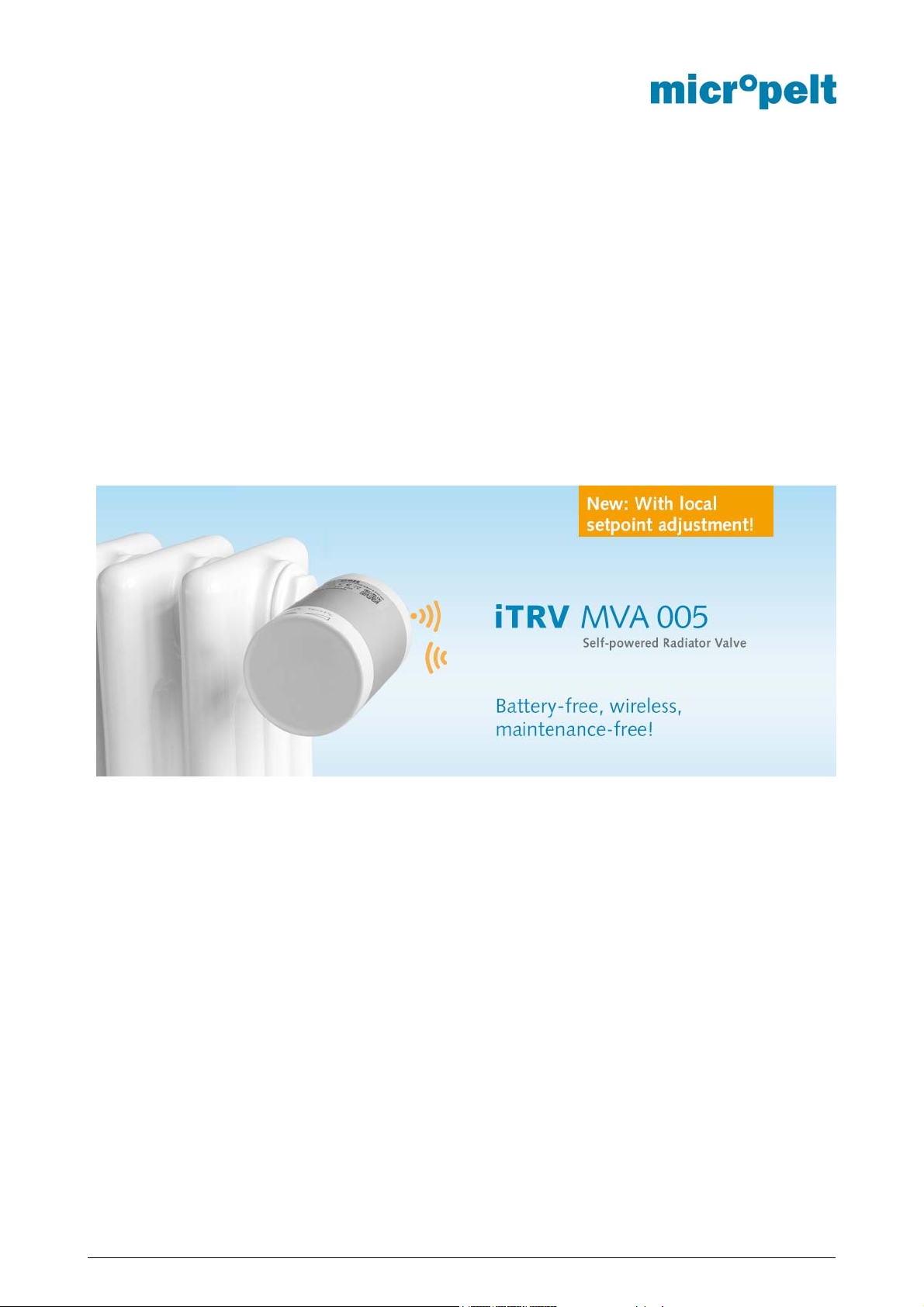
Wireless heating valve actuator
MVA005 EnOcean
User manual and device specification
EnOcean Equipment Profile A5-20-06
Annex: List of adapters and theft protection
MAR2019 Autor: Micropelt - Eine Marke der EH4 GmbH - DokumentenNr.: MVA005_1DS_0319v2e.docx
Page 2

MVA005
User manual and Datasheet
INDEX
INDEX 1
1 Document history 2
2 ERRATA 2
3 Use and safety recommendations 3
4 System description 4
4.1 Picture MVA005 with dial for local control 6
5 Energy-supply through thermal Energy Harvesting 7
6 User Control - Quick overview table 8
6.1 Installation with Manual Pairing (Teach-In) 8
6.2 Local offset 8
6.3 Deactivation and RESET 10
6.4 Installation through SIGNAL telegram and Remote Commissioning 11
6.5 Remarks Remote Commissioning 12
6.6 Flowchart Remote Commissioning 13
6.7 Flowchart Manual RESET 14
6.8 Flowchart Teach-In, Mounting position and activation 15
7 Notes on radio operation 16
7.1 Transmission range 16
7.2 Other interference sources 16
7.3 Loss of communication with the room controller 16
8 EnOcean Equipment Profile EEP A5-20-06 17
8.1 Protocol data overview 17
8.2 Description of individual functions 20
8.2.1 Setpoint Selection (SPS) 20
8.2.2 Operating mode (SP) 20
8.2.3 Local offset (LO) 20
8.2.4 Radio communication interval (RFC) 20
8.2.5 Summer bit (SB) 21
8.2.6 Valve recognition and ACO 21
8.2.7 Window open detection (DWO) 21
8.2.8 Radio strength and com. error (RSS & RCE) 21
8.2.9 Reference Run (Maintenance) 21
8.3 Radio telegram example 22
9 EnOcean Remote Management (ReMan), Remote Commissioning (ReCom) 23
9.1 EnOcean Link Table 23
9.2 Outbound Teach-In 23
9.3 ReMan supported functions 23
9.4 ReCom Standard Functions 24
9.5 ReCom internal MVA Parameter 25
10 Extended Features and Functions 27
11 Product ID and Label 28
12 Performance data 29
13 Mechanical Interface to Radiator Valve 31
14 Annex 1: Adapter list 32
15 Annex 2: Theft protection 33
MAR 2019 Page 1 / 33 MVA005_1DS_0319v2e.docx
Page 3

MVA005
V
User manual and Datasheet
1 Document history
Date Description
31.08.2018
01.10.2018
01.03.2019
Transfer from released German version and first
release English version
Section 10:
Product ID 0x004900000001
Added product label picture
Added SEC CODE default valve
Dissolved Errata MVA005_V5.15.b.3
Added manual RESET SEC CODE
Freeze protection sensor changed from ambient
to flow
Radio loss set point changed
Added 2nd freeze protection value 0°C (SPS=1
and Setpoint 0°C)
Additional flow charts and descriptions
Added LED-signal with temperature sensor
failures (Short circuit, disconnection)
ersion Status
0818_v1e Released
0818_v1e Released
0319v2e.docx Released
2 ERRATA
VERSION
MVA005_V5.15.b.3 RECOM Standard Command RESET TO
RESET SEC CODE TO DEFAULT not
MVA005_V5.26.a.7 4BS radio communication interval 120min
THEMA WORKAROUND
Execute RECOM Operation and write
DEFAULT not supported
supported
not supported
Default values
<>
<>
MAR 2019 Page 2 / 33 MVA005_1DS_0319v2e.docx
Page 4

MVA005
User manual and Datasheet
3 Use and safety recommendations
Dear valued customer,
Thank you for choosing our product. To operate the self-powered radiator actuator, please read this manual
carefully. Keep the instructions for future reference.
In case of questions, please contact:
Micropelt - a brand of EH4 GmbH. Email: info@micropelt.com. Telephone +49 7665 932183 0
Use and safety instructions:
The metallic part of the unit’s housing serves as a heat sink. Be sure that the air circulation around it
is not obstructed by furniture, curtains, plants, or other objects.
If the device has been stored in a cold environment, make sure that it resumes close to room
temperature before use. This is to prevent damaging due to condensation.
The thermostatic radiator valve is designed for indoor use only. Do not allow the thermostatic radiator
valve to get wet. Its sensitive electronics can be affected.
The unit is best cleaned with a dry or slightly damp cloth. Do not use aggressive cleaning agents or
solvents.
Refrain from exposing the unit to environmental stress such as high mechanical forces (do not step
on it), strong vibrations, direct sunlight or extreme temperatures.
The unit must not be disassembled or modified. In case you are unsure how to use the unit, please
get in touch with Micropelt.
Be aware that correct operation can be affected by strong electromagnetic fields. Typical sources of
such are mobile phones, 2-way radios, RC transmitters, microwave ovens, electric motors.
The housing contains actuated springs that can lead to injuries if released. For servicing, refer to
qualified service personnel.
The thermostatic radiator valve has been designed and must solely be used for the purpose of
controlling a M30 x 1.5 heater valve. Any other use may pose a hazard to the device itself, to the
equipment involved, or to the health of the user.
When operating the device in a workplace environment, be sure to observe the workplace regulations
that may apply.
Intended use: The self-powered thermostatic radiator valve is suitable solely for controlling water-filled heating
radiators. Any other use – including control of floor heating systems - is not permitted and can result in damage.
Do not disassemble or modify any part of the product. It is important to comply with the safety notice included
in these operating instructions.
MAR 2019 Page 3 / 33 MVA005_1DS_0319v2e.docx
Page 5

MVA005
User manual and Datasheet
4 System description
This document defines the properties of Micropelt’s battery free, intelligent thermostatic radiator valve (iTRV).
MVA005 is an 868MHz EnOcean wireless actuator, which is self-powered through thermal energy harvesting.
It is used to single room control heating radiators with standard valve connection M30x1.5 (Section 13). To
operate the device, the unit must be paired with a compatible room controller or gateway unit supporting EEP
A5-20-06. The pairing is done either via manual 4BS Teach-In or trough EnOcean Remote Commissioning.
Once mounted and activated on the valve body, a calibration cycle starts to automatically adapt itself to the
individual valve and is ready for use. Adapter are available for a majority of non M30x1.5 valve bodies (Section
14).
Room controller time schedules can be conveniently used to set individual room temperatures at different
times and to a desired °C value. By lowering room temperatures in times of absence, heating costs can be
saved without any loss of comfort. Reducing the room temperature by only a few °C does further add to
reduction of heating energy consumption and respective CO2 pollution.
The actuator generates the required electrical energy for operation (motor, sensors and radio communication)
by means of a built-in thermoelectric generator (TEG) and therefore operates maintenance-free. It is powered
from the temperature difference between the radiator heat and ambient temperature (usually room
temperature). An additional energy source such as a battery or external power supply is not required. The
internal energy storage is fully charged upon delivery, so that sufficient energy is available for installation and
up to approximately one year of operation. In winter and heating season, the actuator then supplies itself
independently trough the converted heat of the heating circuit. Due to the surplus of generated energy in
winter, the internal storage provides sufficient energy for 365 days per year operation including transition
periods and summer.
The product is delivered in mounting position (off) with the valve plunger completely retracted. The drive does
recognize when installed on a valve body by means of internal force and travel distance measurement.
Unmounted activation does allow to execute Remote Commissioning operation (Instant SIGNAL telegram is
transmitted immediately after each activation from mounting position) but will always return the device back to
mounting position to switch off. The drive does have a built-in motor error detection "ACO". The ACO bit does
signal incomplete or unsuccessful reference runs from mounting, motor issues during normal operation as well
as motor runs from mounting position and back to mounting position (Section 8.2.6).
The actuator operates with the EnOcean equipment profiles EEP A5-20-06 in either valve position (% value
transmitted) or temperature setpoint using its internal temperature control loop (°C setpoint transmitted). The
device has a built-in flow temperature sensor to automatically switch its Radio communication cycle (2, 5 or
10 minutes) based on available radiator temperatures. Installation and activation will immediately set the radio
communication interval to every 2 minutes and for an installation period of 30 minutes to provide quicker
feedback (Section 8.2.9). The ambient temperature value transmitted during such installation period is the raw
and actual temperature (Without approximation and smoothing). The device transmits a variety of information
to the room control unit including flow and ambient temperature, received radio signal strength, radio
communication failure, window open detection (Refer to Section 8). The control units responds either with a
new position value in the range 0% (valve closed) to 100% (valve open) or temperature setpoint (0 ... 40°C).
Setpoint changes will be instantly processed and new position values are calculated.
The MVA005 has a red and a green LED to support and indicate successful or failed operations for activation
and deactivation (More details in Section 6).
The device is equipped with a dial for local user setpoint changes that are instantly transmitted to the room
controller. The controller however decides whether or not and how these local changes are accepted and
processed by responding with a corresponding telegram answer that includes or ignores the local change
request. In valve position mode, all local changes are transmitted as relative values. Changes in temperature
setpoint mode are added or subtracted to the current set point temperature and transmitted as absolute
temperature value on the controller (Section 8). Successful local inputs are confirmed by a corresponding
number of discreet ton signals. Successive inputs within a maximum time period of 5 seconds time are
transmitted as a result value to the room controller. Example: 2 x right (+ 2°C) followed by 2 tone signals.
Within the 5 seconds period 3 x left (-3°C) followed by 3 tones. The result of -1°C is transferred after 5 seconds
MAR 2019 Page 4 / 33 MVA005_1DS_0319v2e.docx
Page 6

MVA005
User manual and Datasheet
on the room control unit. There will be no further tone signal to confirm the result of -1°C. Incorrect inputs will
be displayed by an approx. 2 seconds long red LED signal. Failed attempts will require a waiting period of 2
seconds. Local changes will lead to an instant telegram transmission to the room controller. In case of no
response from the correspondent room controller, another telegram will be transmitted 1 second later.
Integrated temperature sensors (valve body and environment) are both used to control the radio interval and
internal temperature controller, window-detection as well as freeze protection. The ambient sensor is used to
measure the room temperature. During heating operation, the ambient sensor is influenced by the near-field
of the radiator as well as self-heating of the metallic device housing. The resulting temperature failure due to
offset is compensated on the basis of the flow sensor and a built-in temperature compensation
(approximation), as well as a subsequent smoothing function. Within the first 30 minutes after activation, the
actuator sends the actual ambient temperature without any corrections. After 30 minutes, the device sets the
ambient temperature to its smoothing start value to 20°C that will be kept as long as the calibration cycle takes.
The approximation process in a non-heating cycle takes 3 x 10 minutes. Device activation in an active heating
cycle will extend the start value and smoothing cycle to as long as the measured ambient and flow sensor
values stabilize with deviations smaller than 1°C. When operated in temperature setpoint, the use of an
external room temperature sensor is recommended which is then transmitted to the MVA005 with every 4BS
telegram through the room controller. Without external room sensor, the built-in ambient sensor is used with
the respective in accuracy given the nearfield radiator environment or any other related effects such as
mounting position, curtains, furniture. (See picture 4.1).
Anti-freeze protection uses the flow sensor integrated in the metallic valve connection. Standard freeze
protection is active at <6°C. With a temperature setpoint transmission of 0°C, than the freeze protection
temperature is also lowered to 0°C. It does not matter if the 0°C setpoint value was requested by radio or by
manual adjustment.
Alternate flashing of red and green LEDs in 0.5 second intervals signals a sensor error (short circuit or
interruption). In this condition, normal operation is not possible.
Window open detects any temperature drop within a time period of 2 minutes on the local ambient temperature
sensor. Once a given negative temperature change is detected, the device sets the DWO bit (Section 8.2.7)
and immediately reports the state transmitting a 4BS telegram to the room controller. Its transmitted ambient
temperature is the actual temperature value (no approximation or smoothing). The window open detection
function is limited to the transmission of data telegrams and setting the DWO bit, no further internal reactions
by the actuator apply. The detection of a temperature drop depends on a recognizable stream of cold air in
the close environment of the actuator. For a reliable detection, the drive must be installed in unspoilt situation
and on radiators below the respective window. Fully opened windows in winter season are usually reliably
detected at low outside ambient temperatures. Window in tilt position and heaters in faraway distance to the
window cannot be detected reliable. The window open function is independent of the selected communication
interval and automatically runs every 2 minutes. Should the temperature fall further and below freeze protection
temperature of 6°C (respectively 0°C), the drive automatically opens to prevent from freeze related damages.
Radio failures after 6 unsuccessful 4BS communication attempts in paired situation are reported with its status
bit RCE. The actuator automatically switches to its internal temperature control using the last received and
valid temperature setpoint from the control unit. With the lack of a valid temperature setpoint °C value (e.g.
SPS=0 operation), the internal default value of 21°C is used. Radio signal strength of the received telegram
(RSS) is also activated due to lack of incoming data telegrams. There is no change on the radio communication
cycle. The local offset function of the dial remains active and any local adjustments are calculated from a
default value 21°C. E.g. 5 x left decreases the setpoint from 21°C to 16°C, independent from the last received
setpoint value. Due to lack of response from the master control unit keeps the drive this setpoint and regulates
accordingly. Consecutive local changes are again calculated from the default value of 21°C, e.g. 3 x right =
24°C followed by 1x right = 22°C. The drive returns to normal operation, once the radio communication is reestablished.
When permanently use in unheated rooms, the internal storage will be ultimately discharged. In such
circumstance, the drive automatically opens to 50% for recharging. For operation in unheated rooms, the valve
and its EEP A5-20-06 provide options to reduce and minimize energy consumption through either stand-by
operation (SBY Bit) or summer bit (SB) 8 hours radio interval. Using the local offset input, the drive can at any
time be activated from standby (SBY) and returns to normal operation.
MAR 2019 Page 5 / 33 MVA005_1DS_0319v2e.docx
Page 7
MVA005
User manual and Datasheet
The MVA005 is equipped with hard - and software functions to simplify installation, control and real-time
monitoring. Apart from standard, manual 4BS teach-in are EnOcean Remote Commissioning (ReCom)
operations available to teach and configure the device prior deployment or during operation. ReCom is
operated with separate from 4BS and periodically transmitted SIGNAL (0x09) telegrams. Single or multiple
ReCom commands must be executed within an 8 seconds time period after the UNLOCK command. ReCom
can be used to set its link-table and change device-internal parameters such as control loop gain, temperature
offset parameter or readout of its internal storage value (Refer to Section 9.5).
The drive can be restarted by means of manual RESET (Section 6.5). Holding the dial in one of the two end
positions for 10 seconds restarts the drive, runs a reference run and activates the 30-minute maintenance
interval. The drive then communicates for the next 30 minutes in a 2 minute interval. The ambient temperature
is the effective measured temperature of the ambient sensor. After the maintenance interval, the temperature
approximation and smoothing function restarts. Existing teach-in connections to the room controller and
remote commissioning settings are retained during manual RESET.
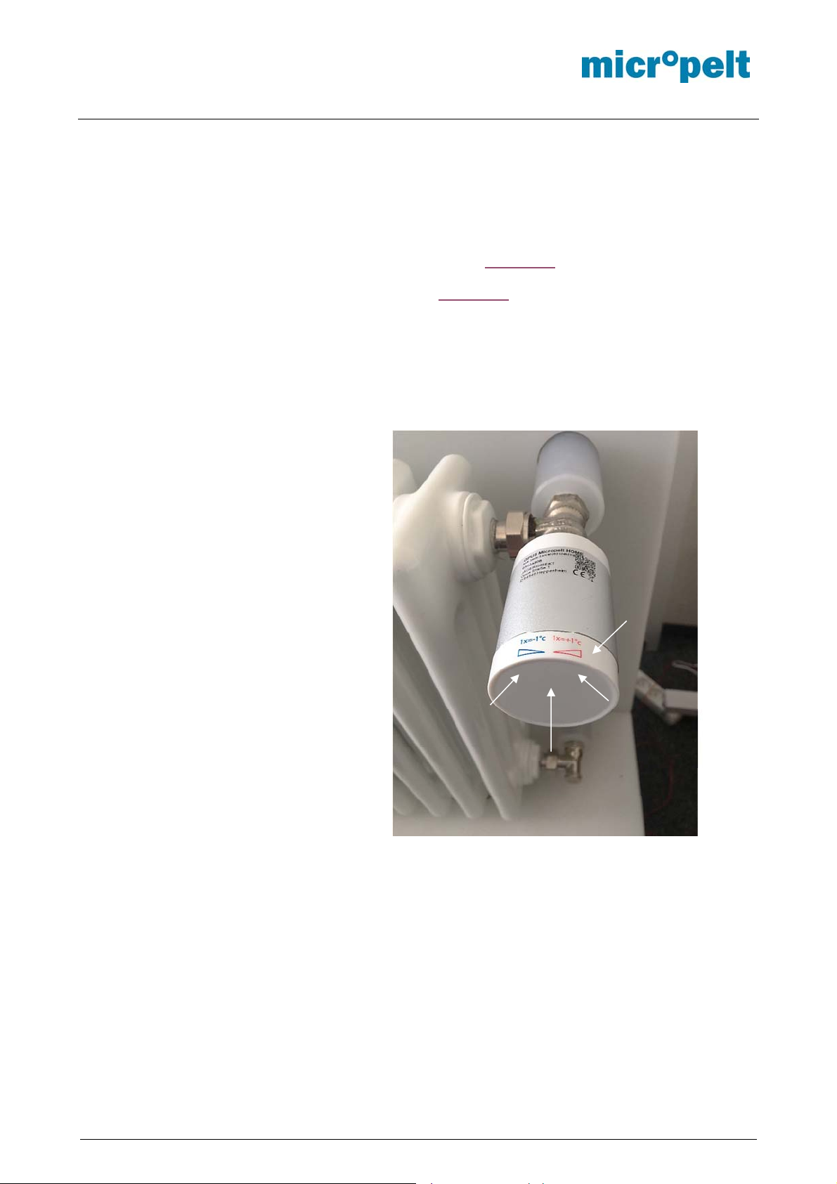
4.1 Picture MVA005 with dial for
local control
Dial for local control with +/- marking.
One Red and Green LED are
positioned below the cover at marked
positions. The ambient temperature
sensor is centrally positioned between
both LEDs.
LED RED
Dial
LED GREEN
Temperature Sensor
below the cover
MAR 2019 Page 6 / 33 MVA005_1DS_0319v2e.docx
Page 8
MVA005
User manual and Datasheet
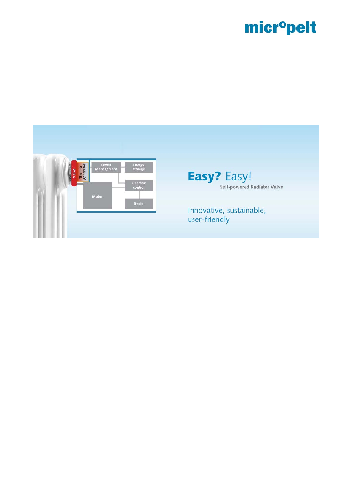
5 Energy-supply through thermal Energy Harvesting
The actuator generates the necessary electrical energy for operation by means of a thermoelectric generator
(TEG), which gains electrical energy from the temperature difference between radiator flow and room
temperature. During the heating season, excess energy is accumulated in the internal storage for operation in
transition periods and summer. The energy balance of the actuator is designed to allow operation through 365
days per year when used in typical radiator heating installations.
If, in exceptional cases, the storage voltage drop below a certain limit, the actuator reports this status to the
room controller and takes the protection position (50% valve opening or maintains the set value, whichever is
the higher). Subsequently, the actuator goes to sleep and waits until the memory is re-charged by the
thermoelectric generator back to a sufficient level. As soon as enough energy is available, the actuator
resumes normal operation.
The protection position ensures that the heating valve cannot calcify in an end position and freeze protection
is ensured. Unexpected room temperatures will occur.
MAR 2019 Page 7 / 33 MVA005_1DS_0319v2e.docx
Page 9

MVA005
User manual and Datasheet
6 User Control - Quick overview table
6.1 Installation with Manual Pairing (Teach-In)
No Objective Button
No.
1 Pairing from
mounting
position
(OFF)
OR from
normal
operation
2 Mounting Mount the actuator before
3 Reference run
and normal
operation
Turn dial to
end position
Left OR Right
and hold 5
seconds.
Turn to end
position
Left OR Right
for short press
(< 1 second)
Action LED or Tone
Unit transmits a teach telegram
(1x green LED), connects with
the controlling unit and confirms
the successful teach-in with a
second flash green LED.
The unit remains in mounting
position. Any actuator not in
mounting position will activate
the motor and return to
mounting position to switch off
the device.
executing run-in sequence and
normal operation.
Consider required adapter
(Section 14)
Unit executes run-in sequence
and enters normal operation.
Radio communication will occur
every 2 minutes and for a time
duration of 30 minutes after
activation. Communication after
30 minutes follow the 4BS
settings transmitted by the room
control unit.
Reasons for
activity
After 5
seconds 1x
green LED for
teach sent
Teach-in
successful:
1x green LED
Failure (not
teached):
3x red LED
No tone
signals.
Success:
1x green LED
Failure:
3x red LED
No tone
signals
failure
Controller or
gateway either
not present or
not in pairing
mode, so that
pairing fails
Mounting
failure (e.g.
missing
adapter),
Motor failure,
Gear failure
Unmounted will
return the
motor to
mounting
position and
switch off the
device.
6.2 Local offset
1 Local Offset
Operation in
Temperature
Setpoint (°C)
(Internal
control loop)
MAR 2019 Page 8 / 33 MVA005_1DS_0319v2e.docx
Turn to end
position
Left OR Right
for short
press.
Turn dial left for 1 or up to 5
times until its end position:
Every successful actuation will
decrease the actual setpoint
temperature by 1°C and transmit
the new setpoint as absolute
value.
Turn dial right for 1 or up to 5
times until its end position:
Every successful actuation will
increase the target temperature
by 1°C.
Success:
1 … 5 tone
signals
according the
number of
inputs
Failure:
Red flashing
LED for 2
seconds. (Left
and right
No tone
signals:
No local
actuation
detected or
accepted.
Device is in
mounting
position.
Page 10

MVA005
User manual and Datasheet
2 Local Offset
Operation in
Valve Position
(%)
Turn to end
position
Left OR Right
for short
press.
The temperature setpoint may
be changed by up to +/- 5°C.
Multiple local inputs within one
cycle time frame of 5 seconds
are internally cumulated to one
desired target value.
Individual local input cycles are
open for a max. time window of
5 seconds and concluded with a
telegram transmit including the
desired target temperature as
absolute °C temperature value.
Resulting changes in motor
position will only be executed
when the room controller
confirms the local change with
its responding and next data
telegram.
Turn dial left for 1 or up to 5
times until its end position:
Every successful actuation will
signalize the controller the
desired reduction in target
temperature with a relative value
(e.g. 0x7F for -1)
Turn dial right for 1 or up to 5
times until its end position:
Every successful actuation will
signalize the controller the
desired increase in target
temperature with a relative
value. (0x01 when +1)
The desired temperature
setpoint change communicated
to the controller may be
changed by up to +/- 5.
Multiple local inputs within one
cycle time frame of 5 seconds
are internally cumulated to one
desired target value.
Individual local input cycles are
open for a max. time window of
5 seconds and concluded with a
telegram transmit including the
desired target temperature as
absolute °C temperature value.
Resulting changes in motor
position will be executed when
the room controller confirms the
local change with its responding
and next data telegram.
inputs in one
cycle).
Wait for 10
seconds.
Success:
1 … 5 tone
signals
according the
number of
inputs
Failure:
Red flashing
LED for 2
seconds. (Left
and right
inputs in one
cycle).
Wait for 10
seconds.
No tone
signals:
No local
actuation
detected or
accepted.
Device is in
mounting
position.
MAR 2019 Page 9 / 33 MVA005_1DS_0319v2e.docx
Page 11

MVA005
User manual and Datasheet
6.3 Deactivation and RESET
1 Deactivate,
Move to
mounting
position,
Switch off
Disassembly
2 RESET
followed by
normal
operation.
Turn to end
position
Left OR Right
and hold for at
least 5 sec.
Turn to end
position
Left OR Right
and hold for
10sec.
Green LED appears, than
release.
3x red LED indicates teach-in
failure which however does not
play any role when deactivating
the device. Motor moves back to
mounting position and device
switches off.
Reactivation in mounted position
will restart the device with no
changes to previously set
parameters including link table
settings to enter normal
operation.
Turn dial to left or right until its
end position and hold for at least
10 seconds until the 2nd green
LED appears, than release.
When mounted, teached and
active:
Device enters installation radio
cycle of 2 minutes for a 30
minutes duration. Transmitted
ambient temperature is the raw
and actual temperature (no
approximation, no smoothing).
In case of Radio communication
failure: Device switches to
Temperature setpoint and 21°C.
Success:
After 5
seconds 1x
green LED
followed by 3x
red LED
Failure:
No LED
No tone
signals
Success:
1x green LED
after 5
seconds
followed by a
2nd green
LED after
another 5
seconds
(10 seconds
in total).
No LEDs:
Try again and
hold the dial
end position
tight. Do not
release during
the 5 seconds
time period.
No LEDs:
Try again and
hold the dial
end position
tight. Do not
release during
the 10 seconds
time period.
MAR 2019 Page 10 / 33 MVA005_1DS_0319v2e.docx
Page 12

MVA005
User manual and Datasheet
6.4 Installation through SIGNAL telegram and Remote Commissioning
In order to teach and configure the drive via ReCom, it is mandatory to change the default security code first!
No Objective Button
No.
1 Change
security code
from
mounting
position
2 SIGNAL
and
ReCom from
mounting
position
(Security
code has
been
changed)
1
&
2
3 Configuration
All further standard installation and use procedures are identical with manual teach-in (Sections 6.2 and 6.3):
The commands SEC CODE change, write link table, write parameters can also be performed in a
single ReCom session (note TCM Maturity Time).
with SIGNAL
and ReCom
from normal
operation
(Security
code has
already been
changed)
Assembly
Reference run → Normal operation
Setpoint adjustment
Mounting position = Off → Disassemble
Manual reset
Turn dial to
end position
Left OR Right
for short
press.
Turn to end
position
Left OR Right
for short
press.
NONE The drive sends a SIGNAL
Action LED or Tone
activity
The drive is activated and sends
a SIGNAL telegram. The room
controller changes the default
security code of the drive and
prepares it for the configuration.
The device then carries out a
reference run. When mounted,
the drive activates and transmits
a 4BS telegram every 2 minutes,
as well as every 12 hours
(default) a SIGNAL telegram.
Unmounted: Device goes into
the mounting position and shuts
off.
The unit activates and transmits
one single SIGNAL telegram to
allow the controller to change
desired Linktable and/or
parameter.
Device executes Reference run
to either activate (mounted) or
return to mounting position and
switch off (unmounted). Each
Signal telegram will be followed
by standard 4BS telegram.
telegram every 12h (default
interval), giving the room
controller the opportunity to
configure.
Thereafter, the drive continues
its normal operation
NONE
No tone
signals
Successful
execution of
device
internal
ReCom
Parameter:
green-redred
Successful
execution of
device
internal
ReCom
Parameter:
green-redred
Reasons for
failure
If the drive
does not react
to ReCom
communicatio
n, then the
change in the
security code
may have
failed.
If the drive
cannot be
configured, the
security code
may not be
changed
successfully
MAR 2019 Page 11 / 33 MVA005_1DS_0319v2e.docx
Page 13

MVA005
User manual and Datasheet
Note: As long as the link table is not correctly described (no teach-in), the drive will remain in self-controlled
mode at 21°C and does ignore any room controller. Local inputs / changes to the setpoint temperature on the
dial are possible. Local entries lead to the immediate transmission of a data telegram.
6.5 Remarks Remote Commissioning
The ReCom specification of the EnOcean Alliance applies
ReMan / ReCom processes are executed in response to the signal sent by the drive (SIG)
SIG telegrams are sent:
o Every time the drive is started from the installation position
o For drives in operation: Deactivate the drive by turning it against the left or right stop, hold
for 5 seconds until 1x green LED, release, 3x red LED
o Cyclic, during operation and parallel to regular 4BS communication in a default time interval
of 12 hours
NOTE: The SIG telegram interval can only be changed by means of ReCom (see product
specification).
The maximum waiting time for an UNLOCK response to a signal telegram is 1 second
NOTE: Analogous to 4BS communication on A5-20-01 and A5-20-06
ReCom starts with an UNLOCK, the required Default Security Code (SC) is 0x53C65E34
Writing the link table and parameters requires prior modification of the Default Security Code
Invalid SCs (0x00000000 and 0xFFFFFFFF) are automatically reset to the default SC
Changing the SC plus writing the link table plus writing parameters can be done in one pass.
The sequence of processing individual parameters or sequence of link table / parameter is freely
selectable.
NOTE: Note the Maturity time of the radio module with successive commands.
The maximum available time window between UNLOCK and LOCK is 8 seconds
If there is physical access to the device, the SEC CODE can be manually reset to its default value
Proceed as follows:
1st. Bring the device into the assembly position
2nd. Turn the adjusting wheel to the left against the stop and hold
→ After 5 seconds 1x green LED, after another 5 second 1x green LED
3rd. Turn to the right within one second and hold for 5 seconds
→ 1x green LED
4th. Within 2 seconds, turn 2x briefly to the left against the stop
→ 2x green LED
→ The SEC CODE has been reset to its default value 0x53C65E34
MAR 2019 Page 12 / 33 MVA005_1DS_0319v2e.docx
Page 14

MVA005
User manual and Datasheet
6.6 Flowchart Remote Commissioning
6.6.1 Typical ReCom-procedure
Wait for SIGNAL Telegram
MAX. TIME WINDOW TO
UNLOCK = 1 SECOND
(RORG SIG)
UNLOCK 0x0001
Signal Telegrams are transmitted:
a. Instantly when device is activated from mounting position. To
deactivate: Turn local control device to end position left or right and
hold for 5 seconds until 1x green LED followed by 3x red LED. To
activate the device turn to end position left or right for short press
(<1 second).
b. Periodically and independent from 4BS telegrams. Default cycle time
is 12h.
Signal Telegramme werden gesendet:
a. Sofort bei Aktivierung aus der Montagepositon. Gerät deaktivieren in
die Montageposition durch Stellrad nach Links oder Rechts bis
Anschlag und 5 Sekunden halten bis 1x grüne LED gefolgt von 3x
rote LED. Aktivieren durch kurzes halten des Stellrades nach Links
oder Rechts (< 1 Sekunde).
b. Periodisch und unabhängig von 4BS Telegrammen. Default
NO (Default SEC CODE = 0x53C65E34)
MAX. TIME WINDOW
BETWEEN UNLOCK AND
LOCK = 8 SECONDS
SEC CODE already
changed?
YES
SET LINK TABLE 0x0212
GET LINK TABLE 0x0211
SET DEVICE CONFIG. 0x0231
GET DEVICE CONFIG. 0x0230
GET PRODUCT ID 0x0227
LOCK 0x002
6.6.1 Reset Security code through invalid SEC CODE values
Wait for SIGNAL Telegram
(RORG SIG)
SET CODE 0x0003
Command sequence in any order
(Refer to Section 9)
Kommandos in beliebiger Reihenfolge
(Siehe auch Abschnitt 9)
UNLOCK 0x0001
SEC CODE is RESET to
manufacturer Default value =
0x53C65E34
SEC CODE already
changed?
YES
EXAMPLE 0x78DC9AB9
SET CODE 0x0003
0xFFFFFFFF OR
0x00000000
NO
Default SEC CODE = 0x53C65E34
INVALID / UNGÜLTIGE
SEC CODES
MAR 2019 Page 13 / 33 MVA005_1DS_0319v2e.docx
Page 15

MVA005
User manual and Datasheet
6.7 Flowchart Manual RESET
Use r‐
input
Afterfurther5sec1xgree n LED,
..hasvalidzerorefe rence *
Mot or movesto
50%posi ti on
2xred LED
(ProcessorRestart)
TurnDi altoleftor
rightuntil itsend
position ..
..andhold
After5sec1xgreenLED
Dial..
.. hel d
release dial
Devi ce ..
..andrelease
Activationlocaloffset
ManualTeach &
..rele ased
...isinmountingposition
(novalidzero pointrefe rence)
(ProcessorRestart)
mountingposition
2xred LED
.. mounted
correctl y
1x gree nLED
(referenceruncorrect)
Devi ce for30min.in
maintenancemode*
Devi ceisin
normal
operation
Mot or movesto
mountingposition
Motorexecutes
refe rencerun
Devi ce
is..
.. notmounted
correctl y
3x re dLED
(novalvedetected)
Motormov esbackto
mountingposition
Devi ceisin
mountingposition
=off
Motormov estoend
position
Devi ceisin
mountingposition
=off
activate withmanual
action onitsdial
MAR 2019 Page 14 / 33 MVA005_1DS_0319v2e.docx
Page 16

MVA005
User manual and Datasheet
6.8 Flowchart Teach-In, Mounting position and activation
User ‐
input
After5sec1xgreenLED
..holdfor10sec.
ManualRESET
TurnDial toleftor
right untili tsend
position ..
..held
Dial..
..notconf irm ed
..releas ed
Radiotransmits
Teach ‐InRequest
1x greenLED
teach‐tel egram
transmitted
Teach‐In..
3xredLED
..andreleas e
ManualTeach &
mountingposition
..confi rmed
Mot ormove sto
mountingposition
Activationlocaloffset
1x greenLED
..correcti on
withnew
input
..noresponse
within1sec*
Device is
in..
..normaloperation
Localoffset
Tone signal
1xtone
5sec
watingtime
User ..
Radiotransmits
User ‐Offset
Radio
recei ve s ..
Radiotransmits
User ‐Offse tagain
..mountingposition(off)
..instant
response
Activation
Moto rexecutes
refe rence run
Devi ce i s
..
.. mounted
1x greenLED
(succe ssf ulrefere nce
run)
Devi ce f or30min.in
maintenancemode*
.. notmounted
3x red LED
(novalvedetected)
Moto rmovesbackto
mountingposition
Devi ce i sin
mountingposition
=off
activatewithmanual
action on itsdial
Devi ceisin
mountingposition
=off
activatewithmanual
action on itsdial
* Remarks to the flowcharts 6.5 and 6.6
"no response within 1 sec”
"does (not) have a valid zero point
reference”
"maintenance mode"
Devi ceisin
normal
operation
Device has received no radio answer and therefore transmits the user
offset a second time.
With radio answer from the controller, only one telegram is sent
The device receives its zero reference by a reference run. He loses it by
driving in mounting position.
Note: A device that has been unscrewed from the valve without moving to
mounting position retains its zero reference!
In this mode, the device communicates the actual measured
uncompensated ambient temperature. In addition, the radio period is 2
min.
After 30 minutes, the device switches to normal operation.
MAR 2019 Page 15 / 33 MVA005_1DS_0319v2e.docx
Page 17

MVA005
User manual and Datasheet
7 Notes on radio operation
7.1 Transmission range
The radio transmission range is limited by both the distance between transmitter and receiver, and by
interference. Indoors, building materials play an important role. Major reflections and signal losses are due to
metallic parts, such as reinforcements in walls and metallized foils, which are used on thermal insulation
products.
Penetration of radio signals:
Material Penetration
Wood, gypsum, uncoated glass 90..100 %
Brick, chipboard 65.. 95 %
Reinforced concrete 10.. 90 %
Metal, aluminum facings 0.. 10 %
For an evaluation of the environment, please see guide values listed below:
Conditions Range / penetration
Line-of-sight Typ 30 m range in passages, up to 100 m in
halls
Plasterboard and wood walls Typ 30 m range through max. 5 walls
Brick and foamed concrete walls Typ 20 m range through max. 3 walls
Reinforced concrete walls & ceilings Typ 10 m range through max. 1 ceiling
Supply blocks and lift shafts should be treated as shields.
In addition, the angle at which the signal enters the wall has to be considered. A shallow angle increases the
effective wall strength as well as the attenuation of the signal. Whenever possible, signals should enter walls
perpendicularly. Alcoves should be circumvented.
For additional information, refer to the EnOcean White Paper “EnOcean Wireless
Systems – Range Planning Guide”.
7.2 Other interference sources
Common sources of interference are devices that generate high-frequency signals. These are typically
computers, audio-/video systems, electronic transformers and ballasts. The distance of the actuator to such
devices should be more than 0.5 m.
7.3 Loss of communication with the room controller
If the actuator cannot establish a dependable radio communication with the room controller, i.e. more than 6
times in sequence the room controller does not receive a radio signal, then the actuator switches to a
reduced radio pattern. The typical 10 minute radio period is extended to one transmission every hour,
reducing the energy consumption while radio contact is interrupted. In addition, the actuator enters the safe
position. Once the radio contact to the room controller recovers, the actuator reverts to requesting
instructions from the controller every 10 minutes.
MAR 2019 Page 16 / 33 MVA005_1DS_0319v2e.docx
Page 18

MVA005
V
User manual and Datasheet
8 EnOcean Equipment Profile EEP A5-20-06
Radio communication is periodically and bidirectional exclusively following the Micropelt designed and
MVA005 customized EnOcean Equipment Profile EEP A5 20-06 (Harvesting-powered actuator with local
temperature offset control (BI-DIR).
8.1 Protocol data overview
From MVA005 to Control unit: (DIRECTION-1: TRANSMIT DATA - FROM ACT to RCU)
Offset Size Bit-
range
0 8
8 1 DB2.7
9 7
DB3.7...
DB3.0
DB2.6 …
DB2.0
Data Short-
Cut
Current value CV
Local Offset
Mode
Local Offset LO
LOM
Description
Current Valve
position
Local Offset Mode
defines the format of
LO
LOM =1, use with temperature setpoint mode (DIR-2,
DB1.2, SPS = 1)
Current temperature
set-point plus /
minus local offset
are communicated
as an absolute
temperature value
[°C]
LOM = 0, use with valve position mode (DIR-2, DB1.2,
SPS = 0)
Local offset setting
is communicated
directly
alid
Range
0…100dec 0…100 %
101…255 (0x65…0xFF) reserved
0 = LO is relative
(temperature offset)
1 = LO is absolute
(temperature with offset)
Temperature setpoint °C +/- local
offset °C
0…80dec 0…+40 ºC
81…255 (0x51…0xFF)
reserved
0x0: 0 °C (Default)
0x1: 1 °C
0x2: 2 °C
0x3: 3 °C
0x4: 4 °C
0x5: 5 °C
0x7B:-5 °C
0x7C:-4 °C
0x7D:-3 °C
0x7E:-2 °C
0x7F:-1 °C
Scale Unit
Local ambient temperature:
0…80dec 0…+40 °C
81…254 (0x51…0xFE) reserved
Feed temperature:
0…160dec 0…+80 °C
161…254 (0xA1…0xFE) reserved
0xFF = Sensor failure or out of
range (either ambient or feed or
both of them)
0: Ambient sensor temp
1: Feed sensor temperature
0: Not harvesting
1: Harvesting active
0: Low, almost discharged
1: Sufficiently charged
16 8
24 1 DB0.7
25 1 DB0.6
26 1 DB0.5
DB1.7…
DB1.0
Temperature TMP
Temperature
Energy Input
Selection
Enabled
Energy
Storage
Local Ambient
or
Feed temperature
(Selected by
Direction 2, DB1.1)
Indicates which
TSL
ENIE Harvesting status
ES
sensor is used for
TMP
Charge level of
energy storage
MAR 2019 Page 17 / 33 MVA005_1DS_0319v2e.docx
Page 19

MVA005
V
User manual and Datasheet
27 1 DB0.4
28 1 DB0.3 LRN Bit LRNB Telegram type
29 1 DB0.2
30 1 DB0.1
31 1 DB0.0
Window open
detection
Radio Com
Error
Radio Signal
Strength
Actuator
obstructed
DWO
RCE
RSS
ACO
Window open
detection
Indicates radio
communication
errors
Weak radio signal
warning
Reports blocked
actuator (motor)
Reference run not
successfully
completed
0: No open window detected
1: Open window detected
0: Teach-in telegram
1: Data telegram
0: Radio communication is stable
1: Six or more consecutive radio
communication errors have
occurred
0: Radio signal is strong
1: Radio signal is weak
(-77 dBm or less)
0: Actuator working correctly
1: Actuator is blocked
From Control unit to MVA005: (DIRECTION-2 RECEIVE DATA - FROM RCU TO ACT)
Offset Size Bit-
range
0 8
DB3.7…
DB3.0
Data Short-
Cut
Valve position
or
Temperature
Setpoint
SP
Description
Valve Position
or
Temperature
Setpoint
Selection with
DB1.2
alid
Range
0..100dec 0…100 %
101…255 (0x65…0xFF)
reserved
Or
0…80dec 0…+40 ºC
81…255 (0x51…0xFF) reserved
Scale Unit
8 8
16 1 DB1.7
17 3
20 1 DB1.3 Summer Bit SB
21 1 DB1.2
DB2.7…
DB2.0
DB1.6…
DB1.4
Temperature
from RCU
Reference
Run
RF
Communicatio
n interval
Set Point
Selection
TMP
REF
RFC
SPS
Room temperature
from room control
unit (RCU)
Execute referencerun
Radio duty cycle
selection.
Find additional
information in the
Appendix
Initiate summer
mode (reduced
communication)
Setpoint selection
for DB3
0..160dec 0…+40 °C
161…254 (0xA1…0xFE)
reserved
Special values 0 and 0xFF:
IF SPS=1, use actuator-internal
temperature sensor.
0: Normal operation
1: Reference-run
0b000: AUTO (default)
2, 5 or 10 minutes
0b001: 2 minutes
0b010: 5 minutes
0b011: 10 minutes
0b100: 20 minutes
0b101: 30 minutes
0b110: 60 minutes
0b111: 120 minutes
0: Normal operation
1: Summer mode with
8h radio duty cycle
0: Valve position mode
(0…100%)
1: Temperature setpoint
(0…40°C), actuator internal temperature
controller is used
MAR 2019 Page 18 / 33 MVA005_1DS_0319v2e.docx
Page 20

MVA005
User manual and Datasheet
Temperature
22 1 DB1.1
23 1 DB1.0 Standby SBY
24 4
28 1 DB0.3 LRN Bit LRNB LRN Bit
29 3
DB0.7…
DB0.4
DB0.2…
DB0.0
Temperature
Selection
Not used Set to 0
Not used Set to 0
TSL
requested from the
actuator
(DB1.7…DB1.0,
DIR-1, TMP)
Enter standby
mode, refer to
Appendix
Further details can be found on www.enocean-alliance.org.
0: Request ambient
temperature
1: Request feed
temperature
0: Normal operation
1: Standby
0: Teach-in telegram
1: Data telegram
MAR 2019 Page 19 / 33 MVA005_1DS_0319v2e.docx
Page 21

MVA005
User manual and Datasheet
8.2 Description of individual functions
Pls. also refer to the officially published EEP A5-20-06 description and Table 8.1
8.2.1 Setpoint Selection (SPS)
DIRECTION-2.
Selection whether A5-20-06 and the actuator is used with Valve Position (Controller running in the room or
building control system) or with its internal temperature control loop.
8.2.2 Operating mode (SP)
DIRECTION-2.
Setpoint Temperature °C:
The controller transmits the temperature setpoint for the internal controller (0 ... + 40°C, DB3.0 ... DB3.7 = 0
... 80). The use of a separate, external room temperature sensor is recommended whose room temperature
(DB2.0 ... DB2.7) is transmitted to the drive by the room controller as part of the A5-20-06 protocol. The internal
controller thus does not use the ambient temperature measured in the near field of the radiator, but the actual
room temperature. When operating with an internal temperature sensor, DB2.0 ... DB2.7 must be set to 0x00.
Every values not equal to zero (0x00) is interpreted as a valid room temperature value and thus will be used
and potentially result in faulty control behavior.
Valve position %:
The controller transmits 0 ... 100% (DB3.0 ... DB3.7 = 0 ... 100) and converts it into an actuating movement by
the actuator (0% = closed valve / 100% = completely open valve).
8.2.3 Local offset (LO)
DIRECTION-1.
The MVA005 local offset (LO) function offers a convenient way for end users to request temperature changes
locally at the actuator/radiator while the room control unit may be out of reach or may not be accessible at the
time of the desired temperature change. Nevertheless, LO follows a master (control unit) and slave (MVA005)
structure, which requires the control units to confirm any local change with corresponding data sent to the
respective actuator device.
Setpoint Temperature °C:
Local changes of +/- 1°C … +/- 5°C will be transmitted to the control unit as absolute °C value calculated from
the effective setpoint, plus or minus the desired °C value change. Example: Setpoint controller = 21°C + 2°C
local offset change = 23°C transmitted value.
Valve position %:
Local changes of +/- 1°C … +/- 5°C will be transmitted to the control unit as relative value.
8.2.4 Radio communication interval (RFC)
DIRECTION-2.
The 4BS radio communication interval of the actuator can be freely determined within the EEP specified range
by the room controller. This allows to e.g. reduce radio traffic and power consumption when outside of the
heating times (e.g. overnight, absence, setback mode), while in heating periods the response times of the
drive can be shortened. In default “auto” setting, the drive uses and varies between 2, 5 and 10 minutes based
on its internal flow temperature sensor. (2 minutes at T flow> 50 ° C, 5 minutes at T flow> 45 ° C, otherwise
10 minutes). Continuous operation with a radio interval of less than 5 minutes leads to increased energy
consumption and faster discharge of the internal storage. Short radio intervals must be coordinated with the
available flow temperature and heating times. If necessary, check the voltage of the internal memory by means
of remote commissioning.
MAR 2019 Page 20 / 33 MVA005_1DS_0319v2e.docx
Page 22

MVA005
User manual and Datasheet
SIGNAL telegram cycle time can also be changed within the specified range through Remote Commissioning.
Pls. refer to the DDF and Section 9.5.
8.2.5 Summer bit (SB)
DIRECTION-2.
The actuator receives the status bit summer mode from the external controller through Standard 4BS message.
The valve closes while the radio communication interval is increased to once every 8 hours. It is possible to
wake up the iTRV through any local control setting. The actuator executes and transmits the local change and
continues with normal operation (unless the controller does transmit the summer bit again).
8.2.6 Valve recognition and ACO
The valve actuator does have a built-in valve recognition by means of force and distance measurement. Selfcalibration is executed every time it moves to 0% position (full close). During operation the valve actuator does
a full stroke (self-calibration) once per week to avoid malfunction of the valve. It is not needed to trigger the
self-calibration (reference runs) through the control unit.
8.2.7 Window open detection (DWO)
DIRECTION-1.
Negative temperature changes within a given time period (2 minutes) measured with the ambient sensor are
used to detect open windows. The MVA005 immediately sets the DWO bit according to A5-20-06 and triggers
a 4BS standard telegram transmission to the room controller for further processing (e.g. closing the radiator
for 30 minutes). The window open detection function is limited to the transmission of data telegrams and setting
the DWO bit, no further internal reactions by the actuator apply.
Should the temperature fall further and below freeze protection temperature of 6°C, the drive automatically
opens to prevent from freeze related damages. DWO measurements are executed regularly within a 2 minutes
cycle and independent from the standard radio communication cycle set by the room controller. The window
open DWO is cleared as soon as the ambient temperature does not measure the specified changes over time.
8.2.8 Radio strength and com. error (RSS & RCE)
DIRECTION-1
The RSS (Radio signal strength) Bit is used to provide feedback about the radio signal strength of received
telegrams from its control unit, which will be helpful to analyze the radio quality in both directions. Received
telegram signal strength of <-80dBm will set the RSS bit. RCE (Radio communication error) is used to signal
radio loss following 6 consecutive missing data telegrams from the control unit to the valve actuator. In case
of RCE, the RSS bit will also be set.
8.2.9 Reference Run (Maintenance)
By setting the REF bit, the drive executes a reference run and restarts. The communication interval is set to 2
minutes (maintenance interval) for the next 30 minutes and the (uncorrected) ambient temperature measured
at the drive is transmitted. When the 30 minutes have elapsed, the temperature approximation and smoothing
restarts. 21 ° C are set as the default temperature setpoint, but they are overwritten by the first valid telegram
of the room controller.
MAR 2019 Page 21 / 33 MVA005_1DS_0319v2e.docx
Page 23

MVA005
User manual and Datasheet
8.3 Radio telegram example
DIRECTION-1 MVA005 to Control unit /Gateway
MVA005 → Controller / Gateway
4 Byte:
BYTE HEX BIN DEC
DB3.7-0
DB2.7-0
LOM DB2.7 1
DB2.6-0 2A 0101010 42 LO = Setpoint with User Offset = 21.0 ºC
DB1.7-0
DB0.7-0
TSL DB0.7 1
ENIE DB0.6 1
ES DB0.5 1
DWO DB0.4 0
LRNB DB0.3 1
RCE DB0.2 0
RSS DB0.1 0
ACO DB0.0 0
16AA6EE8
16
AA
6E
E8
00010110 22 CV = Current valve opening = 22 %
10101010 170
0 = Relative local offset 1 = Setpoint with local offset added
01101110 110 TMP = Feed temperature = 55 ºC
11101000 232
0 = TMP is ambient sensor temp
0 = No harvesting
0 = Energy storage low
0 = No window open 1 = Window open detected
0 = Teach-in Telegram
0 = Radio link OK 1 = Radio communication error
0 = Radio signal stable 1 = Radio quality low (RSSI < -80 dBm)
0 = Actuator operating normally 1 = Actuator obstructed
DIRECTION-2 Control unit / Gateway to MVA005
Controller / Gateway → MVA005
4 Byte:
BYTE HEX BIN DEC
DB3.7-0
DB2.7-0
DB1.7-0
RES DB1.7 0
DB1.6-4 4 100 4 RFC = Radio communication interval = 20 min
SB DB1.3 0
SPS DB1.2 1
TSL DB1.1 0
SBY DB1.0 0
DB0.7-0
DB0.7-4 0 0000
LRNB DB0.3 1
DB0.2-0 0 000
30684408
30
01000101 69 SP = Valve position = 48 %
68
10100000 160 TMP = Temperature from RCU = 26 ºC
44
01000100 68
08
00001000 8
SP = Valve temperature setpoint = 24 ºC
0 = Normal operation 1 = Execute reset
0 = Normal Operation 1 = Summer bit, extended sleep time
0 = DB3 is valve position [%]
0 = Request ambient temp from actor 1 = Request feed temp from actor
0 = Normal operation 1 = Standby (wakeup by pushbutton)
0 = not used
0 = Teach-in telegram
0 = not used
Further details can be found on www.enocean-alliance.org.
1 = TMP is feed sensor temperature
1 = Harvesting
1 = Energy storage sufficiently charged
1 = Data Telegram
1 = DB3 is temperature set point [ºC]
1 = Data telegram
MAR 2019 Page 22 / 33 MVA005_1DS_0319v2e.docx
Page 24

MVA005
User manual and Datasheet
9 EnOcean Remote Management (ReMan), Remote Commissioning (ReCom)
9.1 EnOcean Link Table
MVA005 supports the following number of tech-in relationships:
Inbound EnOcean Link Table: 0 Teach-in relationships (not existing)
Outbound EnOcean Link Table: 3 Tech-in relationships
Comment:
MVA005 uses an outbound link table only, inbound relationships are not supported. Manually erasing the
outbound link table is not possible. Manual pairing (teach-in) however overwrites the first entry of the
outbound link table, clearing the other two entries.
9.2 Outbound Teach-In
Outbound teach-in is supported for EEP A5-20-06 (4BS).
Two options are available to teach-in MVA005 with an external Gateway/Controller:
Manual via teach-in message (4BS version 3)
Remote commissioning
9.3 ReMan supported functions
PING
LOCK, UNLOCK
SET CODE
QUERY ID, QUERY STATUS
Comments:
MVA005 Default Security Code = 0x53C65E34.
Invalid security codes: 0x00000000; 0xFFFFFFFF
Invalid security code settings will be automatically converted in to the default code 0x53C65E34 to ensure
further access through Remote Management.
For further details, pls. refer to the document “Remote Management” by EnOcean GmbH:
https://www.enocean.com/fileadmin/redaktion/pdf/tec_docs/RemoteManagement.pdf
MAR 2019 Page 23 / 33 MVA005_1DS_0319v2e.docx
Page 25

MVA005
User manual and Datasheet
9.4 ReCom Standard Functions
Remote Commissioning Mandatory Commands Bundle:
Remote Commissioning Acknowledge
Get Product ID Query & Response
EnOcean Link Table Basic Commands Bundle
Get Link Table Metadata Query & Response
Get Link Table Query & Response
Set Link Table Content
Configuration Parameters Bundle
Get Device Configuration Query & Response
Set Common Configuration Query
*1
RESET DEVICE DEFAULTS
*1
RESET DEVICE DEFAULTS:
Immediately after executing the Reset_To_Defaults command, the device is reset to the manufacturer status
and restarted. The internal memory is reset (1x red LED) and the drive is started (2x red LED). The
manufacturer default parameters are reloaded (see Table 9.5 "DEFAULT" values). The motor then moves to
the mounting position and performs a reference run. When installed, the drive is started in the maintenance
interval. Unmounted, the drive remains in the mounting position and shuts off. All entries of the link table and
the security code remain unaffected.
MAR 2019 Page 24 / 33 MVA005_1DS_0319v2e.docx
Page 26

MVA005
User manual and Datasheet
9.5 ReCom internal MVA Parameter
Pls. contact Micropelt for further details and device description file (DDF, xml).
Description INDEX 0 = Ambient to Target Offset [K]
The ambient to target offset parameter [K] is related to a function to correct the ambient temperature
measured in the actuator. Due to its mechanical design and the near field of the radiator, the temperature
measured is subject to deviations relative to the actual room temperature. In automatic mode (0x00), the
drive uses its integrated flow sensor (valve adapter) to determine the actual room temperature value with
its internal approximation function. In all other settings than automatic mode, an absolute value is
subtracted from or added to the effective measured temperature. Example setting 0x07 = +3K: The
temperature output by the ambient sensor is the effectively measured temperature minus 3°C.
Description INDEX 1 = Radio communication interval [s/min]
The radio interval is only relevant when operating in radio communication failure mode (RCE, or controller
disabled) and controls the transmit interval of 4BS standard telegrams according to A5-20-06. In standard
operation, the 4BS defined radio interval will always override the parameter internal setting.
Description INDEX 11 = Ambient to Target Offset (A) Parameter
The so-called “A” parameter is used within the internal temperature approximation function to calculate
ambient temperature corrections based on actual measured flow (valve adapter) temperatures. In steady
sensor state, the A factor describes the level of parallel shift of the ambient temperature. Function [T
Approximated = T Ambient - ((T Flow - T Ambient) * Offset A Parameter)]. Differences in time constants
when radiators are turned on and off are compensated with an overlaying smoothing function to eliminate
temperature peaks. The smoothing function is based 2 internal arrays with 3 consecutive temperature
values that are compared in its deviations (<1°C) over a time period of 3 x 10 minutes.
Description INDEX 12 = Temperature Control Gain „P“ Parameter (only when SPS = 1)
The P parameter describes the gain/multiplier within the temperature control loop (only when SPS = 1) to
calculate the valve adjustment % value. The default value of 90 corresponds to a valve opening of 18%
when T Ambient the Setpoint temperature difference is 1°C. Note: The Automatic Ambient to Target Offset
(Index 0 = 0x00) mode does us the approximated temperature to calculate the valve opening value, which
is why the corresponding valve opening angles may be different to the above mentioned calculated value.
Description INDEX 14 = Signal Communication Interval
The signal communication interval can be changed from its default value of 12 hours to carry out Remote
commissioning operations with short(er) time intervals.
Parameter INDEX Description
Ambient to Target Offset [K] 0
Radio communication interval
[s/min]
1 (0x00) 0…Auto * (DEFAULT)
(0x00) 0 … Auto* (DEFAULT)
(0x01) 1 … -3 K
(0x02) 2 … -2 K
(0x03) 3 … -1
(0x04) 4 … 0 K
(0x05) 5 … +1 K
(0x06) 6 … +2 K
(0x07) 7 … +3 K
…
(0x0F) 15 … +11 K
(0x01) 1 … 10sec (For debug only)
(0x02) 2 … 2min
(0x03) 3 … 5min
(0x04) 4 … 10 min
(0x05) 5 … 20min
(0x06) 6 … 30min
MAR 2019 Page 25 / 33 MVA005_1DS_0319v2e.docx
Page 27

MVA005
User manual and Datasheet
* Automatic mode: 2/5/10 Minutes based on
measured Flow temperature and internal storage
voltage
Execute reference run 10 0x01
DEFAULT 0x00
Ambient to Target Offset (A)
Parameter
Temperature Control Gain „P“
Parameter
Internal storage voltage (V) 13
Signal communication cycle
NOTE: Setting of summer bit (8h
4BS communication cycle) does
not change the SIGNAL telegram
cycle.
11 (0x00 … 0xFF) 0 … 255
MVA005 DEFAULT DEZ 56 = HEX 0x38
12 (0x00 … 0xFF) 0 … 255
DEFAULT DEZ 90 = HEX 0x5A
(0x00 … 0xFF) 0 … 255
NUR LESEN
14 0x00 … 1min
Example: HEX 0x21 = DEZ 33 : 10 = 3,3 Volt
0x01 … 5min
0x02 … 10min
0x03 … 20min
0x04 … 60min
0x05 … 120min
0x06 … 240min
0x07 … 360min
0x08 … 720min
0x09 … 1440min
Default: 720min (12h)
MAR 2019 Page 26 / 33 MVA005_1DS_0319v2e.docx
Page 28

MVA005
User manual and Datasheet
10 Extended Features and Functions
Micropelt’s latest generation of wireless heating valve actuators integrate and support a number of features
and functions that allow any time and over-the-air status check and monitoring. Internal sensor and
performance data have been stored over a longer time period accessible through a serial data dump.
Unlike the remote commissioning functions listed, the following Data logs are only accessible on request:
Data log readout of battery open-circuit voltage V
Data log readout of harvester open-circuit voltage V
Data log readout ambient temperature °C
Data log readout of flow pipe temperature °C
The above mentioned data log data‘s may not be available in the current MVA005 product release.
Pls. get in touch with Micropelt to get the latest status.
MAR 2019 Page 27 / 33 MVA005_1DS_0319v2e.docx
Page 29

MVA005
User manual and Datasheet
11 Product ID and Label
The MVA005 Product ID consists of the Micropelt manufacturer ID as well as the product reference number.
All functions and properties are available electronically as Device Description File (DDF).
Device Manufacturer ID Product Reference
MVA005 0x0049 0x00000001
EAN Number MVA005 = 42 6054801 003 9
The label of each actuator is structured according to the guidelines of the EnOcean Alliance QR Code
specification and includes the EURID (EnOcean Unique Radio Identifier) as well as the product ID. In addition
to this mandatory information, the label also includes the manufacturer-specific and default ReMan security
code, which can be changed via the ReMan command Set_CODE.
The Micropelt MVA005 barcode does include:
Label includes:
30S EURID_48bit EnOcean Unique Radio Identifier, 6 Byte Hexadecimal
1P 004900000001 ManID und Product Reference
Pls note: REMAN Default Security Code = 0x53C65E34 (Container 10z and 11Z have been removed from
the barcode)
Product Label example:
MAR 2019 Page 28 / 33 MVA005_1DS_0319v2e.docx
Page 30

MVA005
User manual and Datasheet
12 Performance data
Parameter
Valve thread M 30 x 1,5 (adapter available for other types)
Ambient operating temperature 0 - 40°C, max 70% rH
Flow pipe temperature 75°C max
Transportation & storage temperature
range
Max pin stroke (calibration range) > 5 mm
Operating pin stroke (0-100 %) 2.5 mm typical
Pin Stroke Resolution (defined by
EnOcean Equipment Profile A5-20-01)
Adjustment speed 0.95 mm/s typical
Stall force 100 N typical
Noise level ~ 30 dB(A)
RF communication interval According to A5-20-06
RF communication interval
Activation / installation
Ambient Temperature
Activation / installation
Freeze protection Below 6ºC, open valve to 95%
Window open detection Yes
Safe position
(following 6 consecutive communication
failures)
EnOcean EEP
EnOcean Remote management &
Remote commissioning
DDF (Device description file) Yes
Life cycle status and monitoring
capabilities
Local offset control +/- 5°C
Accuracy of ambient and flow
temperature sensor
Ambient temperature sensor offset
compensation
Energy storage
Energy generation minimum
requirement
Battery voltage flag Battery voltage < 3.1 V
Radio carrier frequency 868.3 MHz
-10 - +45°C, max 70% rH
(Change has to be 3% from current physical position)
(Will revert to A5-20-06 settings after 30 minutes)
Effective Ambient sensor value
(Will revert to approximated value after 30 minutes.
Calibration time in radiator closed situation 3 x 10 Minutes.
Start value smoothing = 20°C); requires stable flow
temperature when heating is on.
Normal operation when T flow > 6°C
0°C when setpoint temperature = 0°C
Internal temperature controller with last valid setpoint °C,
otherwise default value 21°C
Will revert to standard operation as soon as radio
communication is online again
(Valve Position or Setpoint Temperature)
(Pls. contact Micropelt)
Default: Automatic Offset compensation
(Configurable through Remote Commissioning)
Construed for full year operation
90 standard heating days per year with T flow >45°C
(RF communication interval will be set to 10 minutes)
Range
Steps of 1%
2 Minutes
A5-20-06
Yes (Section 9)
Yes
(Section 8
(Section 4)
+/- 0.5 ºC
)
MAR 2019 Page 29 / 33 MVA005_1DS_0319v2e.docx
Page 31

MVA005
User manual and Datasheet
Maximum radiated power +1.4 dBm (EN 300220-2:V3.1.1)
Receiver Category 2 (EN 300 220-1 V3.1.1)
Conformity CE
MAR 2019 Page 30 / 33 MVA005_1DS_0319v2e.docx
Page 32

MVA005
User manual and Datasheet
13 Mechanical Interface to Radiator Valve
The MVA005 is designed to mount directly onto an M30 x 1.5mm radiator valve bodies.
Other valve types are available, see next section 14 .
MAR 2019 Page 31 / 33 MVA005_1DS_0319v2e.docx
Page 33

MVA005
User manual and Datasheet
14 Annex 1: Adapter list
In case of other valve body types, please get in touch with Micropelt:
Email: info@micropelt.com Phone: +49 7665 932183 0
Danfoss Series 2
(M20 x 1.0)
Item no. 9703-24.700
Danfoss Series 3
(M23.5 x 1.5)
Item no. 9704-24.700
Danfoss RA2000
Item no. MVA-AdapterRA2
Adapter Comap
(M28 x 1.5)
Item no. 9700-55.700
Danfoss RAV-L
(26 mm)
Item no. 9700-24.700
Adapter TA
(M28 x 1.5)
Item no. 9701-28.700
Adapter Oventrop
(M30 x 1.0)
Item no. 9700-10.700
Danfoss RAV
Item no. 9800-24.700
Adapter Vaillant
( 30 mm)
Item no. 9700-27.700
Adapter Herz
(M28 x 1.5)
Item no. 9700-30.700
MAR 2019 Page 32 / 33 MVA005_1DS_0319v2e.docx
Adapter Markaryd
(M28 x 1.5)
Art-No. 9700-41.700
Adapter Giacomini
(ca. 22.6 mm)
Item no. 9700-33.700
Page 34

MVA005
User manual and Datasheet
15 Annex 2: Theft protection
Pls. contact Micropelt to receive more information about MVA‐DS01 theft protection solution.
Stainless steel clamp with distance
rings and security screw (requires
special tool to open)
MAR 2019 Page 33 / 33 MVA005_1DS_0319v2e.docx
 Loading...