

SD808 - USER MANUAL
VERSION
DESCRIPTION
DATE
APPROVAL
1
Initial version
2012/04/30
2012/05/03
2
Protocol version
2012/06/03
2012/06/03
3
Controller and application revision
2014/07/02
2014/07/17
4
Enable mode suppression, application
of track numbers and activation
2016/06/03
2016/06/05
4.1
Format
2016/06/03
2016/06/05
4.2
Format
2016/06/19
2016/06/19
4.3
English translation
2017/06/03
2017/06/07
5
Better explanation of track mode
2016/09/19
2016/09/19
5.1
Connection drawings of serial and
track mode.
2018/05/30
2018/06/01
NAME
DATE
SIGNATURE
AUTHOR
Mario Aliaga
2012/04/30
REVISION
Fermín Alarcón
2012/05/02
APPROVAL
Jesús Caum
2012/05/03
Change Management
Information about document
Page 2 of 35

SD808 - USER MANUAL
Index
1 Presentation ..................................................................... 5
2 Initial Precautions ............................................................ 6
3 Connections .................................................................... 7
4 Power Supply ................................................................. 10
5 Motors............................................................................. 10
5.1 Motor current...................................................................................11
5.2 Temperature Control ......................................................................12
5.3 Limit Switch ......................................................................................12
6 Operation Modes .......................................................... 13
6.1 Serial mode .....................................................................................13
6.2 Track mode .....................................................................................13
7 Communications ........................................................... 13
7.1 Driver Configuration........................................................................14
7.2 Motion Command ..........................................................................15
7.3 Dynamic State Request ..................................................................16
7.4 Static State Request ........................................................................17
7.5 Tracks Settings .................................................................................18
8 Speed Profile .................................................................. 20
8.1 Speed Limits ....................................................................................21
9 Communication Example ............................................ 22
9.1 Control Frame .................................................................................22
9.2 Configuration Frame .......................................................................23
10 Software ......................................................................... 25
10.1 Communications ............................................................................27
10.2 Configuration ..................................................................................28
10.3 Serial ................................................................................................30
10.4 Track ................................................................................................32
Page 3 of 35

SD808 - USER MANUAL
11 Specifications ................................................................ 34
11.1 Electrical Values .............................................................................34
11.2 Mechanical Dimensions .................................................................35
Page 4 of 35

SD808 - USER MANUAL
MicroPaP products have a 1 year warranty against any
defects in manufacture. Furthermore, for the first 15 days,
MicroPaP guarantees the reimbursement of the purchase
price if the equipment is damaged or does not meet your
expectations.
1 Presentation
Thank you for purchasing the new MICROPAP EASY MOTION SD-808 driver.
SD-808 is a circuit designed for the operation of bipolar step motors with serial
RS-485 communication.
Main Features:
RS-485 asynchronous serial port galvanically isolated.
Serial mode of up to 32 devices connected in bus.
Movements in complete steps (8 micro steps), 1/2, 1/16, 1/32 or 1/64.
24-byte control frames (ASCII)
Execution of improved speed profiles.
Wide range of power supplies (24 -72 VDC).
Programmable phase current by means of PC software
Maximum current adjustment 8A phase in 40mA increments.
Setting of current standstill at 15, 40, 55 and 75% of the predefined maximum
current value.
Sinusoidal current control with harmonic suppression.
Input for End / Stop in switch mode or PNP with auxiliary power.
Opto-coupled auxiliary inputs.
Protections: temperature and voltage.
Plug connectors.
DIN rail mounting (optional).
Page 5 of 35

SD808 - USER MANUAL
Before connecting the equipment to a RS-485 bus, all the
required parameters for its correct operation must be
configured in point-to-point mode. Remember 120 ohm
resistors on two bus end points!
2 Initial Precautions
Make sure you read the information on motor current adjustment and motor connection
method with special wiring configurations carefully.
Make sure that the power supply has enough power.
Choose wires with a suitable section, without pre-tinning or with pressed tips
and as short as possible.
Be sure to configure the motor characteristics before using the controller.
A USB-RS485 converter is required, microPaP can supply this as an option.
When the driver is starting up, wait until the green LED is turned on and the
red LED is permanently switched off so that the device is in working condition.
Page 6 of 35

SD808 - USER MANUAL
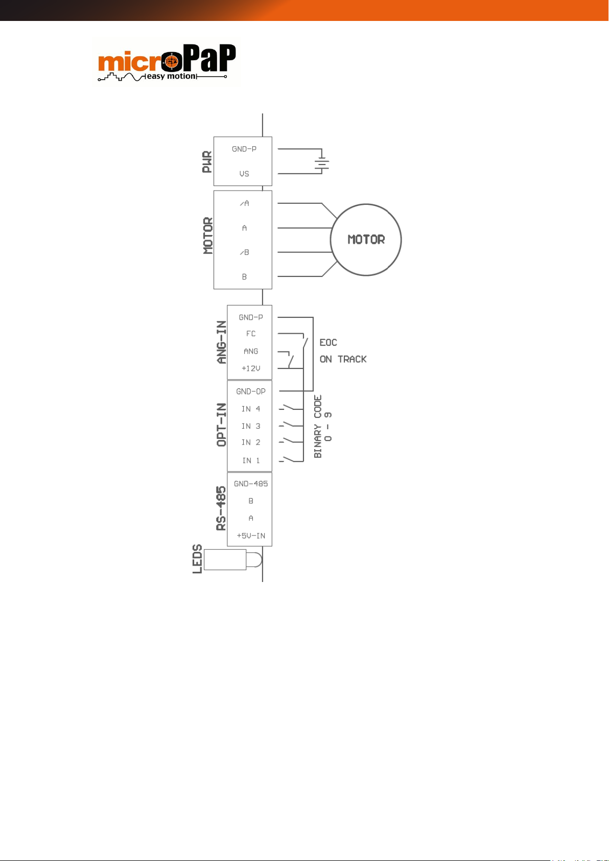
3 Connections
The SD-808 has plug-in terminals of different pitch (to minimize connection errors) for
communication signals, auxiliary input, limit switches and power connectors.
Figure 1 Serial mode connections
Page 7 of 35
SD808 - USER MANUAL
Figure 2 Track mode connections
Page 8 of 35
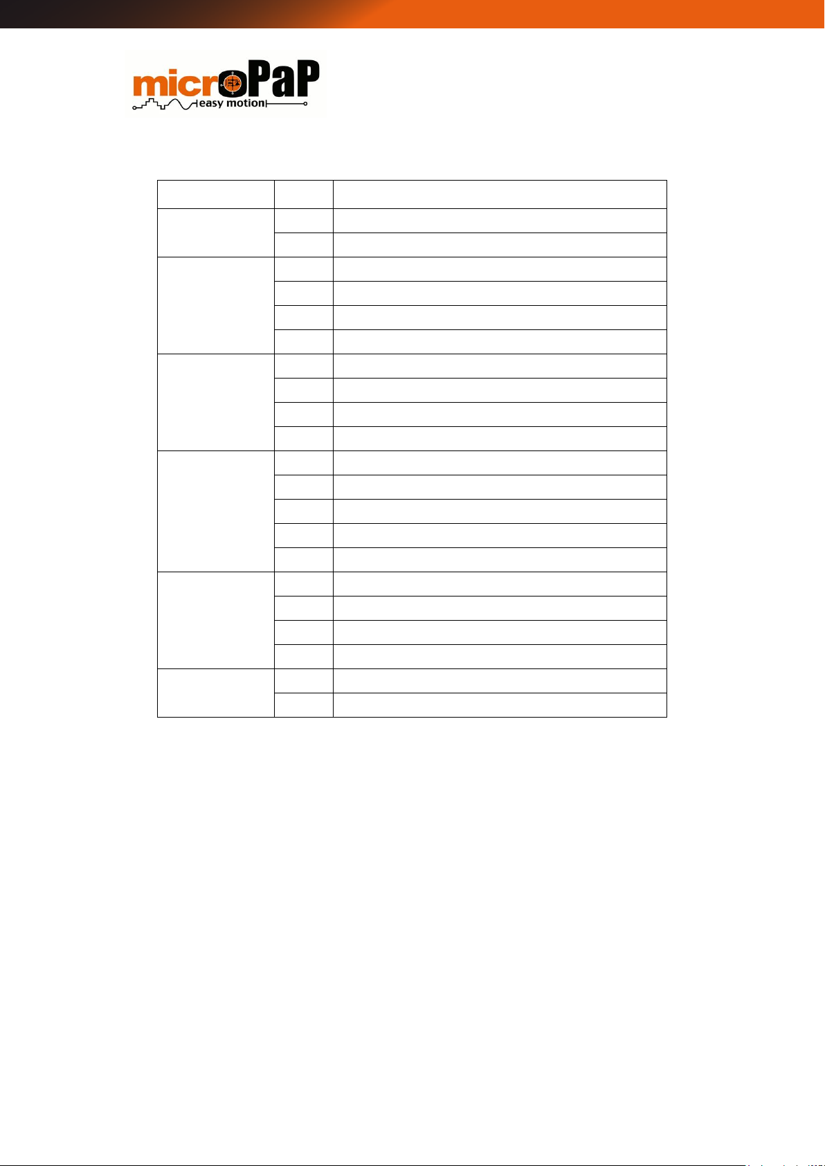
SD808 - USER MANUAL
CONNECTOR
PIN
SIGNAL
PWR
1
+ V (Supply voltage)
2
GND_P (Ground) (*)
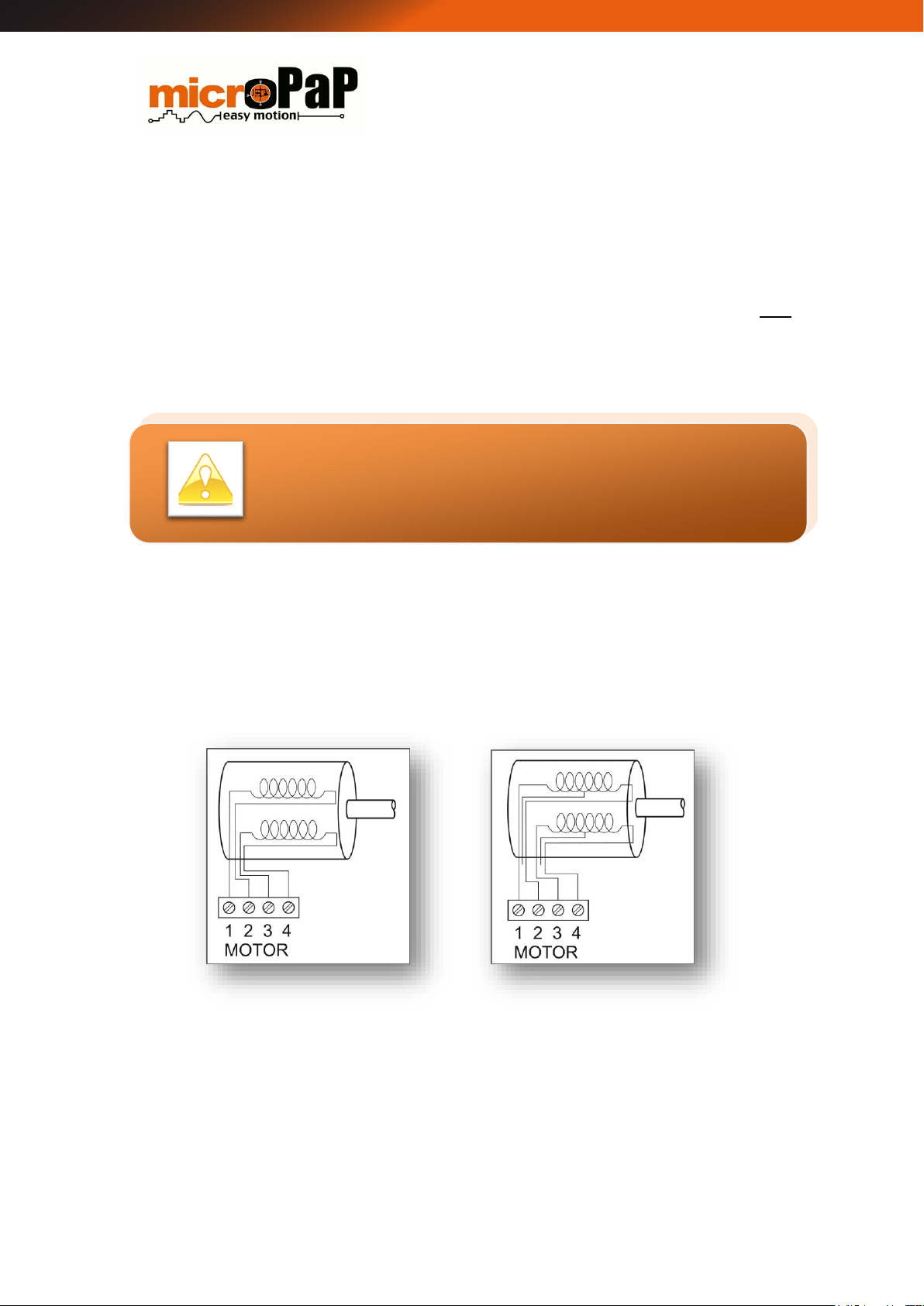
MOTOR
1
Phase B (Connect to the extreme 1 of first motor coil)
2
Phase /B (Connect to the extreme 2 of first motor coil)
3
Phase A (Connect to the extreme 1 of second motor coil)
4
Phase /A (Connect to the extreme 2 of second motor coil)
ANG_IN
1
+12V (Auxiliary power supply 12VDC)
2
ANG (Analog input or track activation)
3
FC (Switch Limit)
4
GND_P (Negative) (*)
OPT_IN
1
IN1 (Optocoupled auxiliary input 1)
2
IN2 (Optocoupled auxiliary input 2)
3
IN3 (Optocoupled auxiliary input 3)
4
IN4 (Optocoupled auxiliary input 4)
5
GND_OP (negative optocoupled inputs) (*)
RS485 (**)
1
+5V 2 A
3
B
4
GND_485 (negative) (*)
LEDS
RED
Flashes at driver’s initialization time. Turn-on during movements
GREEN
Permanent active indicating power and operation of the driver
(*) Las masas del controlador no son comunes.
(**) Precisa de una alimentación externa
Page 9 of 35
SD808 - USER MANUAL
Figure 3 4-wire connection
Figure 4 6-wire connection
Placing outside this allowable power supply voltage rank for
the driver means that the driver protections will activate and
disconnect the power elements.
4 Power Supply
The voltage of the driver’s power supply must be between 24VDC and 72VDC, with a
maximum current of 8A.
The value of the right voltage to power a stepper motor depends on the desired high
maximum speed performance. Increasing the voltage of the driver’s power supply
allows to increase the maximum speed of the motor without loss of steps.
5 Motors
Motors with 4, 6 or 8 wires can be used. The 8-wire motors can be connected in series
or parallel allowing double the torque in the parallel connection.
Page 10 of 35
SD808 - USER MANUAL
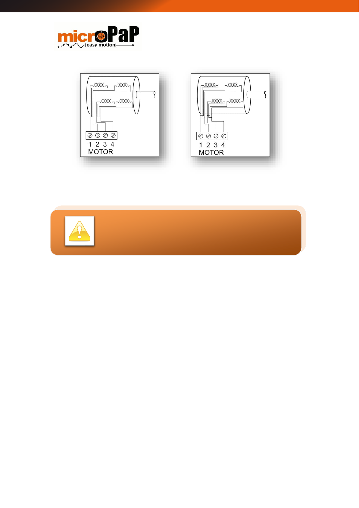
Figure 5 8-wire serial connection
Figure 6 Parallel 8-wire connection
It is very important not to disconnect/connect the motor
with the controller supplied.
Check the connections before turning on the power!
5.1 Motor current
The adjustment of the maximum current provided by the controller must be selected
at the peak rated motor current (Inominal * 1.41) in order to avoid overheating in its
windings which would shorten its life.
The motor current must be set in the controller before the first use. The configuration
is done through the demo program (available free at http://www.micropap.com) and
a USB-RS485 converter.
The current can be adjusted from 400mA up to 8A by 40mA increments. This way,
maximum performance from the motor is ensured.
Page 11 of 35

SD808 - USER MANUAL
The driver must be placed vertically to improve cooling
through the heat sink.
In systems with a lot of electrical noise we strongly
recommend not to use an open circuit limit switch (option 1)
5.2 Temperature Control
The driver self-protects against excessive current demands and associated
temperature risings. The driver includes a heat sink designed to cool the parts of the
circuit which, under normal operation, are subject to heating. For its proper
ventilation, the driver must be maintained vertically.
5.3 Limit Switch
The driver has an input to connect a mechanical Switch Limit or PNP output Switch
Limit. The following figures show the possible connection modes on the terminals 1 (+
12v) and 3 (FC) of the connector ANG_IN.
Figure 7 Switch Limit (FC) Connection Modes
The polarity of the Switch Limit inputs can be changed by customer request.
Page 12 of 35

SD808 - USER MANUAL
6 Operation Modes
The SD-808 driver allows you to work in two different modes:
6.1 Serial mode
In this mode, the movements are made by sending a serial frame from a control device
or PC. Serial communication can be point-to-point or through bus connection of several
drivers.
6.2 Track mode
This mode allows the user to store in the internal memory of the driver up to ten
movements that have been previously configured. Once stored, they can be selected
individually depending on the status of the auxiliary inputs (Figure 2).
This mode is very useful when using the driver in a system with simple and repetitive
movements in totally autonomous mode, since it avoids having to make serial
communications.
For activate desired track its necessary to select a binary code on the inputs IN1 - IN4
in accordance with the track number to be executed and connect the 12V output to
the ANG on the same connector to start the selected track (Figure 2).
The desired stored movement will continuosly executed while the signal on the input
ANG will be present, acting as a “security mushrom”.
7 Communications
Communications work according to the EIA standard RS-485 at 19200 baud, 8 bits of
data, 1 bit of START and 1 bit of STOP. It allows sending the control frames to the
driver according to the protocol described in the following tables.
MicroPaP commercializes a device adapter of USB port (PC) to port RS-485 (Figure 1).
Page 13 of 35

SD808 - USER MANUAL
Nº
byte
Description
Possible values
Error
0
Device identifier
0x30 (initial), 0x31, 0x32,
0x33,... 0x4F
1
Program of functional parameters in
internal memory
81D=0x51=Q
113D=0x71=q
2
Current level
(400mA → 8A) / 40mA
0x30 + current level
(0 a 200)
120D=0x78=x
3
Working mode
S = 0x53 (Serial)
T = 0x54 (Track)
P = 0x50 (Special)
4
New identifier in Serial mode
0x30, 0x31, 0x32,... 0x4F
5
Reserved
0x30
6
Carry Return
0x0D
Nº byte
Description
Possible values
0
Device identifier
0x30, 0x31, 0x32, ..., 0x4F
1
Response identifier to parameters programming
81D = 0x51 = Q
2
Current level
0x30 + current level
(0 a 200)
3
Working mode
0x53, 0x54, 0x50
7.1 Driver Configuration
The configuration of the driver is done through a point-to-point connection and with
initial device identifier 0x30.
The configuration allows to vary, among other parameters, the device identifier, the
maximum current level and the working mode of the device.
Frame format sent to the driver:
Response from the driver:
Page 14 of 35

SD808 - USER MANUAL
4
Device identifier for acting in serial RS-485 mode
0x30, 0x31, 0x32, ..., 0x4F
5
Reserved
0x30
6
Reserved
0x30
7
Carry Return
0x0D
NºByte
Description
Possible Value
Error
0
Device identifier
0x30, 0x31, 0x32, 0x33,... 0x4F
1
Movement command
identifier
77D = 0x4D = M
m=109D=0x6D
2
Number of movement steps
Units (0x30,…,0x39)
x=120D=0x78
3
Tens (0x30,…,0x39)
4
Hundreds (0x30,…,0x39)
5
Thousands (0x30,…,0x39)
6
Tens of thousands (0x30,…,0x39)
7
Hundreds of thousands
(0x30,…,0x39)
8
Direction of the rotation /
Reset accumulated
setpoint
Right = R (0x52)
Left = L (0x4C)
9
Number of steps of the
acceleration slope
Units (0x30,…,0x39)
10
Tens (0x30,…,0x39)
11
Hundreds (0x30,…,0x39)
12
Number of steps for the
deceleration slope
Units (0x30,…,0x39)
13
Tens (0x30,…,0x39)
14
Hundreds (0x30,…,0x39)
15
Speed setpoint in RPM
(0 to 999). (belong to a speed
1 to 1000 rpm)
Units (0x30,…,0x39)
16
Tens (0x30,…,0x39)
17
Hundreds (0x30,…,0x39)
7.2 Motion Command
Frame format sent to the driver:
Page 15 of 35

SD808 - USER MANUAL
18
Microsteps selector and
motor type
200 steps motor
0x31 = ½ steps
0x32 = 8
0x33 = 16
0x34 = 32
0x35 = 64
400 steps motor
0x41 = ½ steps
0x42 = 8
0x43 = 16
0x44 = 32
0x45 = 64
19
STOP current (holding
torque)
0x30 = 15 %
0x31 = 40 %
0x32 = 55 %
0x33 = 75 %
20
Test for Switch Limit
(PNP input type)
0x30 = No test for FC
0x31 = Test for FC
21
Continuous movement
0x30 = Disabled
0x31 = Enabled
22
Final movement response
0x30 = Without response
0x31 = With response
23
Carry Return
0x0D
Nº Byte
Description
Possible values
0
Device identifier
0x30, 0x31, 0x32, 0x33,... 0x4F
1
Command movement identifier
77 = 0x4D = M
2
Error or result
ACK=0x06 (Correct communication)
NACK=0x15 (Communication error)
121= 0x79=y (FC reached)
122=0x7A=z (Movement finished)
3
Carry Return
0x0D
Nº byte
Description
Possible values
Error
Response from the driver:
7.3 Dynamic State Request
Frame format sent to the driver:
Page 16 of 35

SD808 - USER MANUAL
0
Device identifier
0x31, 0x32, 0x33,... 0x4F
1
Dynamic status request
D=68D=0x44
d=100D=0x64
2
Carry Return
0x0D
Nº byte
Description
Possible values
0
Device identifier
0x31, 0x32, 0x33,... 0x4F
1
Dynamic status request identifier
(RAM)
D=68D=0x44
2
Motor state
0x30 = Stop
0x31 = Motor in motion
3
System error (0x00 + error)
LSB bit = Voltage under the
minimum
Bit 1 = Voltage max. exceeded
Bit 2 = Temp. max exceeded
4
Real time temperature
0x30 + Temperature (0 to 200)
5
Real time voltage
0x30 + Voltage (0 to 200)
6
Switch Limit status
0x30 = Un-triggered
0x31 = Triggered
7
Carry Return
0x0D
Nº
byte
Description
Possible
values
Error
0
Static status request (EEPROM) after error
indicating fault
S=83D=0x53
s=115D=0x73
1
Carry Return
0x0D
Response from the driver:
7.4 Static State Request
Frame format sent to the driver:
Response from the driver:
Page 17 of 35

SD808 - USER MANUAL
Nº byte
Description
Possible values
0
Dynamic status request identifier
S=83D=0x53
1
Maximum temperature reached
0x30 + Temperature (0 to 200)
2
Maximum voltage reached
0x30 + Voltage (0 to 200)
3
Programmed current level
0x30 + Current level (0 to 200)
4
Device Mode
S = 0x53 (Serial)
T = 0x54 (Track)
P = 0x50 (Special)
5
Device identifier
0x30 (initial setup)
6
Hardware serial number (0 → 99999)
Units (0x30,…,0x39)
7
Tens (0x30,…,0x39)
8
Hundreds (0x30,…,0x39)
9
Thousands (0x30,…,0x39)
10
Tens of thousands (0x30,…,0x39)
11
Software identifier = ( 0 → 207)
0x30 + Software identifier
12
Software serial number = ( 0 → 207)
0x30 + Software serial number
13
Carry Return
0x0D
Nº byte
Description
Possible values
Error
0
Tracks’ programming
T=84D=0x54
t=116D=0x74
1
Action to execute
R = 0x52 (read)
W = 0x57 (write)
E = 0x45 (delete)
x=120D=0x78
7.5 Tracks Settings
The programming of tracks can only be done through a point-to-point connection with
the driver.
Tracks configuration frame format sent to the driver
Page 18 of 35

SD808 - USER MANUAL
2
Track to read / write / delete
0x30 = Track 0
0x31 = Track 2
…
0x39 = Track 9
6
Carry Return
0x0D
Nº
Byte
Description
Possible values
0
Tracks’ programming
T = 84D = 0x54
1
Track number
0x31, 0x32… 0x39
2
Number of steps (movement)
Units (0x30,…,0x39)
3
Tens (0x30,…,0x39)
4
Hundreds (0x30,…,0x39)
5
Thousands (0x30,…,0x39)
6
Tens of thousands (0x30,…,0x39)
7
Hundreds of thousands
(0x30,…,0x39)
8
Direction of the rotation / Reset
accumulated setpoint
Right = R (0x52)
Left = L (0x4C)
9
Number of steps of the acceleration slope
Units (0x30,…,0x39)
10
Tens (0x30,…,0x39)
11
Hundreds (0x30,…,0x39)
12
Number of steps for the deceleration slope
Units (0x30,…,0x39)
13
Tens (0x30,…,0x39)
14
Hundreds (0x30,…,0x39)
15
Speed setpoint in RPM
(0 to 999). (belong to a velocity 1 to 1000 rpm)
Units (0x30,…,0x39)
16
Tens (0x30,…,0x39)
17
Hundreds (0x30,…,0x39)
Response to the configuration frame from the driver (The answer is the data stored in
the internal memory):
Page 19 of 35

SD808 - USER MANUAL
18
Microsteps selector and motor type
200 steps motor
0x31 = ½ step
0x32 = 8
0x33 = 16
0x34 = 32
0x35 = 64
400 steps motor
0x41 = ½ step
0x42 = 8
0x43 = 16
0x44 = 32
0x45 = 64
19
STOP current (holding torque)
0x30 = 15 %
0x31 = 40 %
0x32 = 55 %
0x33 = 75 %
20
Test Switch Limit
(input PNP type)
0x30 = No test for FC
0x31 = Test for FC
21
Continuous movement
0x30 = Disabled
0x31 = Enabled
22
Final movement response
0x30 = Without response
0x31 = With response
23
Carry Return
0x0D
8 Speed Profile
The motion that the controller can execute follows a speed profile as shown in Figure
7. In this figure, the control points can be observed and in the definition table of the
communication protocol the bytes that define those points.
A speed profile is a way of defining the behaviour of the motor along a movement
originated from a PC (or PLC) command. Generally it improves the speed performance
as it allows to define ramps of acceleration and breaking.
The SD-808 driver allows an acceleration and deceleration (braking) ramp of up to 1000
steps in each of them and a total movement of 1000000 steps.
Page 20 of 35

SD808 - USER MANUAL
200 steps motors
400 steps motors
Full Steps
1000 rpm
1000 rpm
Half Steps
1000 rpm
500 rpm
16 microsteps
900 rpm
500 rpm
32 microsteps
500 rpm
250 rpm
64 microsteps
250 rpm
125 rpm
Figure 8 Speed Profile
8.1 Speed Limits
The system has certain speed limitations that depend on the micro-selector switch,
the selected type of motor and the power supply voltage of the driver. The following
table shows the speed limit values:
Page 21 of 35

SD808 - USER MANUAL
# BYTE
B-0
B-1
B-2
B-3
B-4
B-5
B-6
B-7
B-8
B-9
B-10
B-
11
VALUE
0x31
0x4D
0x30
0x35
0x34
0x33
0x32
0x31
0x52
0x30
0x30
0x36
#
BYTE
B12 B-13 B-14 B-15 B-16 B-17 B-18 B-19 B-20 B-21 B-22
B-23
VALUE
0x30
0x35
0x32
0x39
0x39
0x33
0x31
0x31
0x31
0x30
0x31
0x0D
# BYTE
B-0
B-1
B-2
B-3
VALUE
0x31
0x4D
0x06
0x0D
9 Communication Example
9.1 Control Frame
If you want to make the following motion with an engine:
Device number 1
123450 moving steps.
600 steps of acceleration.
250 braking steps.
Clockwise direction.
Speed 400rpm.
8 micro steps.
1.8 degree motor (200 steps per lap)
Stop current at 15% of rated current.
Looking for a Switch Limit.
Without continuous movement.
Response at the end of the movement.
Frame format sent to the driver:
Answer 1 (Correct communication): The communication has been correct and the
movement has started.
Page 22 of 35

SD808 - USER MANUAL
# BYTE
B-0
B-1
B-2
B-3
VALUE
0x31
0x4D
0x15
0x0D
# BYTE
B-0
B-1
B-2
B-3
VALUE
0x31
0x4D
0x79
0x0D
# BYTE
B-0
B-1
B-2
B-3
VALUE
0x31
0x4D
0x7A
0x0D
Answer 1 (Incorrect communication): The communication has been incorrect.
Movement has not started.
Answer 2: Switch Limit reached.
Answer 3: Movement finished without reaching Switch Limit.
9.2 Configuration Frame
If you want to configure a newly purchased driver with the following parameters:
2.4A current level.
Serial Mode
Device number 5
Current Calculation:
Frame format sent to the driver:
Page 23 of 35

SD808 - USER MANUAL
#
BYTE
B-0
B-1
B-2
B-3
B-4
B-5
B-6
VALUE
0x30
0x51
0x6C
0x53
0x35
0x30
0x0D
#
BYTE
B-0
B-1
B-2
B-3
B-4
B-5
B-6
B-6
VALUE
0x35
0x51
0x6C
0x53
0x35
0x30
0x30
0x0D
We strongly recommend that the motor current and other
parameters are adjusted using the free software provided.
It’s the easy way!
Response from the driver:
The response has been the expected so the driver is reconfigured.
Page 24 of 35

SD808 - USER MANUAL
10 Software
MicroPaP offers an application for the management and configuration of the driver
that can be downloaded from the website (http://www.micropap.com/download).
At the start of the program the following window will appear:
The tabs on the right side of the window allow you to identify and connect the PC port.
Having the SD808 driver connected via USB RS485 converter to the PC the available
ports for connection can be refreshed with the button
Once the communication port to be used has been selected, the connection is made
via the button
Once connected, the driver configuration screen appears, showing five different work
areas. Figure 9 identifies these areas:
Figure 9 Initial Screen
Page 25 of 35

SD808 - USER MANUAL
Working mode selection tabs.
Driver Settings.
Static controller status.
Communications.
Historical actions.
These last two areas, as well as the working mode selection tabs are common in all
working modes that can be given with this controller.
The work mode selection tabs are the following:
Configuration. It allows to assign the controller identifier, the working mode
and the maximum current that will be provided by the controller. The current
configuration of a controller can be checked by reading its static state.
Series. It allows to manage motor movements through serial frames that are
generated and sent from the application to the controller.
Figure 10 Application screen sections. Configuration mode.
Page 26 of 35

SD808 - USER MANUAL
In order to enable the Series, Track and Special tabs, select
the appropriate mode of operation of the driver in the
configuration area / tab.
Track. It allows the generation, execution and storage of up to 10 movements
with different profiles that are called tracks.
Special. Reserved for programming designed especially for the client.
Exit. Allows the application to exit.
10.1 Communications
Communications area, corresponds to the right side of the screen and is common to all
modes of operation of the controller.
In Figure 10 it is shown that the upper part of the area is intended for the selection of
the communications port, in the lower part there is a button which the area reserved
for the representation of frames sent and received can be cleaned with.
Figure 11 Communications area.
Page 27 of 35

SD808 - USER MANUAL
In this window, the frames sent from the PC to the controller are represented in green
and each byte is E =>, on the other hand, the bytes of the frames received from the
controller are represented in blue and each byte is preceded by R <=. In all cases the
representation of the value of given bytes is carried out in hexadecimal format.
Furthermore, if there is an error in the communications, a window appears indicating
the error, as shown in the following figure:
Figure 12 Communications error.
Historical events area. It appears at the bottom of the application tab, as shown in
Figure 9. In this area you can consult all the actions carried out by the application
since its connection.
The following are the screens, with their main characteristics, corresponding to the
different modes of operation of the controller.
10.2 Configuration
If the configuration tab is selected, it is possible to configure the parameters for the
controller. In that sense, figure 12 shows the screen corresponding to the configuration
mode.
All functionalities of the application are based on the allowed options by the
communication protocol.
Page 28 of 35

SD808 - USER MANUAL
Figure 13 Configuration mode screen
Controller parameters to configure are the following:
Real time device identifier: By default, all controllers have ID 0. Thus, if various
controllers are connected to the power supply, each of them will have to be
programmed with a unique identifier. The initial programming of the controller
should be done with a connexion point-to-point and with the controller
disconnected from the power supply.
Device configurations. Possible options:
o Serial.
o Track.
o Special.
Maximum current (mA). Corresponds to the maximum current level that can be
applied to the motor.
Apart from the driver configuration, a static analysis of its status can be also done.
Available values for the static analysis:
Page 29 of 35

SD808 - USER MANUAL
Device identifier.
Maximum working temperature.
Maximum supply tension.
Maximum current.
Configuration of the device: In this point, it is shown whether the driver is
working in serial, track or special mode.
10.3 Serial
The serial tab, allows to send a frame of the movement for a motor connected to the
controller. This frame is composed by different options as can be observed in Figure
13.
Figure 14 Serial mode screen.
Page 30 of 35

SD808 - USER MANUAL
Parameters to configure in the screen:
Device identifier to which the frame has to be sent.
Total number of steps.
Acceleration steps (slider bar).
Breaking steps (slider bar)
Step type:
Complete step
Half step
16 micro steps
32 micro steps
65 micro steps
Number of steps of connected motor (200/400)
Speed in revolutions per minute (rpm)
Rotation direction of the motor (depends on the motor’s connection)
Stop current (In %, referring to the value of maximum current previously
configured)
Searching of Switch Limit, the motor will rotate with the direction and speed
conditions assigned until the detection of a Switch Limit.
Continuous movement. The motor will rotate indefinitely until a frame
modifying the movement conditions is sent.
The controller sends (or not) an answering frame at the end of movement.
Once these parameters are configured, click on the SEND button to send the frame to
the controller.
In this section, it is also possible to make a request of dynamic status that informs
about the following parameters:
Movement (stopped / moving)
Temperature of the system.
Activation of Switch Limit.
Supply voltage
Error
Page 31 of 35

SD808 - USER MANUAL
Figure 14 shows the pop-up window that contains the previous information.
Figure 15 Serial mode screen. Dynamic status.
10.4 Track
Track tab allows the configuration of different movements that will be stored for its
future execution from the controller. Figure 15 shows the corresponding screen of this
mode.
The parameters to configure are:
Device identifier.
Total number of steps
Acceleration steps (slider bar).
Braking steps (slider bar).
Steps type:
Complete step
Half step
16 micro steps
32 micro steps
65 micro steps
Number of steps of connected motor (200/400)
Motor speed (in rpm)
Rotation direction of the motor (depends on the motor’s connection)
Searching of activation Switch Limit.
Page 32 of 35

SD808 - USER MANUAL
Stop current (in %, referring to the value of maximum current previously
configured)
Track number: Up to a maximum of 10 tracks.
Once verified that the motor’s movement is the one wished, using the buttons que el
SAVE, SEND or DELETE the last track will be saved in the controller.
In this section, the track being executed in the controller can be checked.
The parameters that can be checked are the following:
Total number of steps
Acceleration steps
Braking steps
Rotation direction
Figure 16 Track mode screen
Page 33 of 35

SD808 - USER MANUAL
Step type
Rotation steps
Motor speed
Stop current
11 Specifications
11.1 Electrical Values
Supply voltage: 24 a 80 VDC
Phase current: 400mA a 8A (200 levels)
Current phase reduction in stop mode: 25% to 75% in 4 levels
Minimum consumption: 140mA
Communications bus: RS-485 (19200 baud)
Level on digital inputs: 0 to 5V (TTL)
Heat sink: integrated radiator
Functioning temperature: 0 to 85ºC
Humidity: 0 to 95% (without condensation)
Page 34 of 35

SD808 - USER MANUAL
11.2 Mechanical Dimensions
*Dimensions in mm
Page 35 of 35
 Loading...