

Page 1

VTP4
Balanced Line To BNC
VIDEO CONVERTER
TECHNICAL MANUAL
Ref: 2200.5005
micropack.co.uk
Page 2
HELP US TO HELP YOU
Every effort has been made to ensure the accuracy in the contents of our documents; however,
Micropack (Engineering) Ltd can assume no responsibility for any errors or omissions in our
documents or their consequences.
Micropack (Engineering) Ltd would greatly appreciate being informed of any errors or omissions
that may be found in our documents. To this end we include a form, given in Appendix B, for you
to photocopy, complete and return to us so that we take the appropriate action. Thank you.
CONTENTS
TABLE
OF
This document is strictly private and confidential, reproduction without Micropack approval is prohibited. © Micropack Engineering Ltd, 2015
1
Introduction
4
1.1
Overview
4
1.2
Coaxial Video outputs
5
1.3
Led Indications
5 1.4
Balanced Line Video Input
5
2
Safety Instructions
6
2.1
Warnings
6
2.2
Cautions
6
2.3
Important Safety Notices
6
3
Installation
7
3.1
VTP4 Mounting
7
3.2
Mechanical Installation
8
3.3
Field Terminations
8
3.4
Electrical Installation
9
4
Maintenance & Testing
9
VTP4 – Balanced Line To BNC Video Converter
2
Ref 2200.5005
Rev: 4.0
Page 3
micropack.co.uk
5
System Design Guidelines
10
5.1
Power Supply
10
5.2
Balanced Line Video (twisted pair) Input
10
5.3
Video (Coaxial) Output
10
5.4
Earthing & Screening Requirements
10
5.5
Coaxial Video Cable Selection
11
5.6
Balanced Line Video (Twisted Pair) Cable Selection
11
6
Fault Finding
12
6.1
Live Video Images
12
6.2
Replacement and Repair
12
7
Technical Specification
13
7.1
Electrical Specification
13
7.2
Mechanical Specification
13
7.3
Environmental Specification
13
7.4
Certification and Approvals
13
Appendix A
Help us to help you
14
VTP4 – Balanced Line To BNC Video Converter
3
Ref 2200.5005
Rev: 4.0
Page 4
1
Introduction
The Micropack Balanced Line to BNC Video Converter (VTP4 p/n 3100.0010) is used to
convert between Micropack’s Video System twisted pair video cabling (balanced line) and
standard 75R coaxial cabling (BNC) found in commercial video equipment.
The converter has four independent channels. The converter is powered from an
industrial standard 24V supply. The converter has been designed specifically to meet the
needs of an industrial application.
1.1
Overview
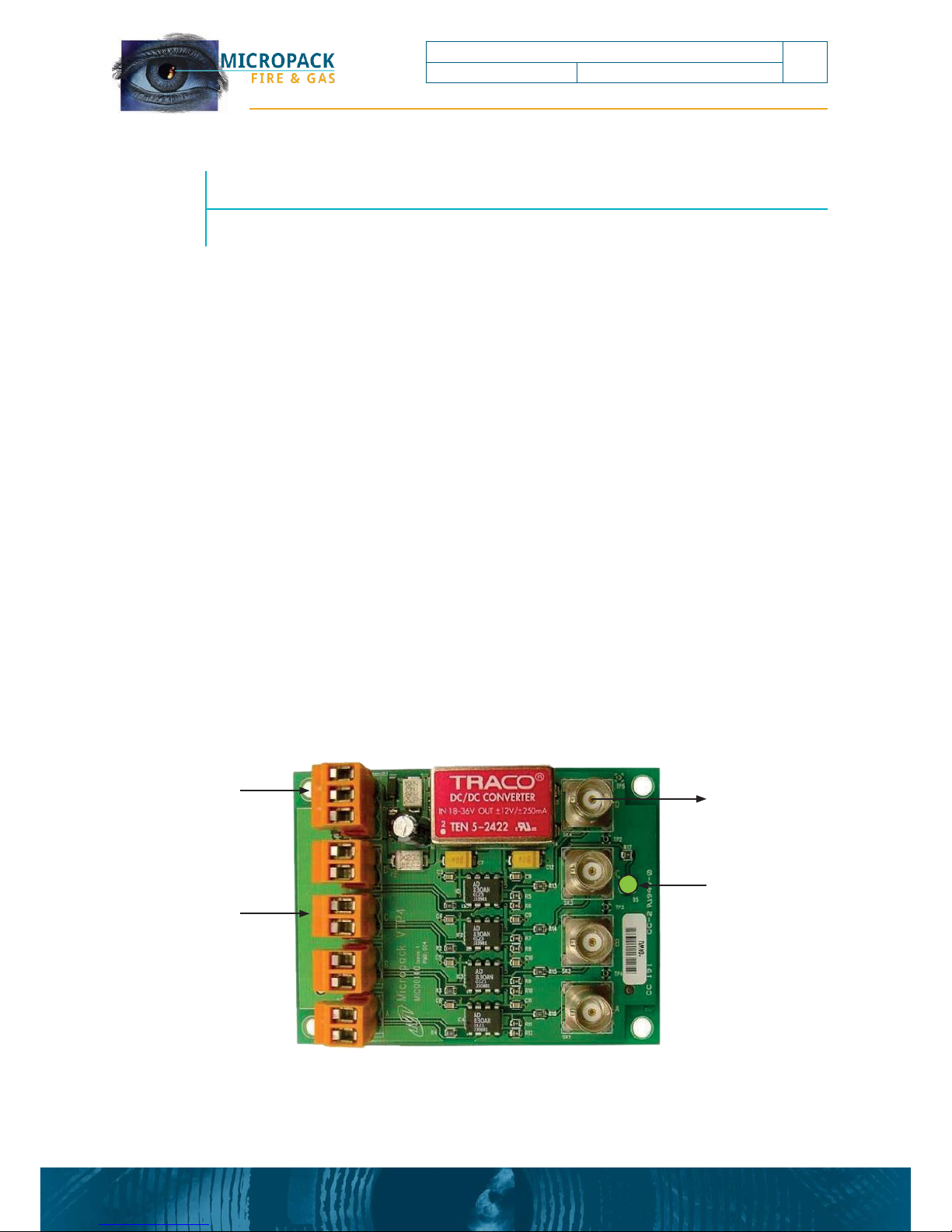
The converter is a single board measuring 100 Length x 70 width (mm). With DIN Rail Mounting
Connection to equipment is via standard BNC female connectors. Connection to the video
system twisted pair cabling is via screw terminals.
below:
The key elements of the converter are shown
Figure 1: Converter Overview
1
2
3
Ch 1
Power Connector
Coaxial Video Output
(BNC) x 4
4
5
Ch 2
Ch 1
Status Indication LED
Balanced Line
Video Input x 4
6
7
Ch 2
Ch 3
8
9
Ch 3
Ch 4
10
11
Ch 4
This document is strictly private and confidential, reproduction without Micropack approval is prohibited. © Micropack Engineering Ltd, 2015
VTP4 – Balanced Line To BNC Video Converter
4
Ref 2200.5005
Rev: 4.0
Page 5

1.2
Coaxial Video outputs
The converters four BNC outputs each support standard 75R coaxial video cabling.
1.3
Led Indications
The LED indicator is used to reveal its current state, as shown below:
Table 1: LED Status Diagnostic Chart
1.4
Balanced Line Video Input
The converters’ four inputs each support balanced line video using a simple twisted pair cable,
note the converter is a balanced line receiver and a coaxial driver. Between two and six balanced
line video devices can be connected to a single transmission line with no spurs or loops. The
connection of balanced line video is very similar to RS485 communications as shown below:
Figure 2: Balanced Line Video
The intended transmission line is a single 150R twisted pair line terminated at both ends in its
characteristic impedance (i.e. 150R line termination resistors fitted at both ends). Only certain
detectors and video switchers have a multi-drop output capability, refer to the relevant technical
manuals for details.
micropack.co.uk
Green LED
Device Condition
Comment
ON
Healthy - Data Transmission in progress
OK
OFF
Power Failed
Check power distribution
VTP4 – Balanced Line To BNC Video Converter
5
Ref 2200.5005
Rev: 4.0
Page 6

2
Safety Instructions
For the correct and effective use of this equipment, to maintain safety and avoid hazards
it is essential that you read and understand these instructions fully, act accordingly
BEFORE installing, operating or maintaining the equipment.
2.1
Warnings
For UK installations BS/EN60079-14 ‘Electrical Installations in Hazardous Areas’ and BS/EN60079-
17 ‘Inspection and Maintenance in Hazardous Areas’ should be strictly observed where the
equipment is located within the hazardous area (a suitable certified enclosure is required.
For installations in North America the National Electrical Code (NEC) should be strictly observed.
Elsewhere the appropriate local or national regulation should be used.
The equipment must be properly earthed to protect against electrical shock and minimise
electrical interference.
Repair of equipment should only be performed in a safe area and by trained personnel.
2.2
Cautions
Use only approved parts and accessories with this equipment.
To maintain safety standards, commissioning and regular maintenance should be performed by
qualified personnel.
2.3
Important Safety Notices
Pay attention to the guidelines given throughout this document.
If in any doubt ask your local sales representative or contact Micropack (Engineering) Ltd.
Micropack (Engineering) Ltd take no responsibility for installation and/or use of its equipment if
this is not in accordance with the appropriate issue and/or amendment of the manual.
Micropack (Engineering) Ltd reserve the right to change or revise the information contain herein
without notice and without obligation to notify any person or organisation of such action.
This document is strictly private and confidential, reproduction without Micropack approval is prohibited. © Micropack Engineering Ltd, 2015
PAY ATTENTION TO ALL SAFETY WARNINGS AND CAUTIONS
VTP4 – Balanced Line To BNC Video Converter
6
Ref 2200.5005
Rev: 4.0
Page 7

3
Installation
Experience has shown that poor installation and commissioning practice may result in poor video
quality that is prone to malfunction.
3.1
VTP4 Mounting
The VTP4 converter can be mounted in the following methods:
• Direct Chassis Mounting (using the four mounting points)
• DIN Rail Mounting (using the optional carrier)
In general the mounting arrangements should be free from vibration, movement or the
potential for accidental knocking or forces acting on the connections and to be isolated as far
as possible from the sources of local interference and allow ease of access to the equipment for
maintenance and repair.
micropack.co.uk
VTP4 – Balanced Line To BNC Video Converter
7
Ref 2200.5005
Rev: 4.0
Page 8
3.2
Mechanical Installation
3.3
Field Terminations
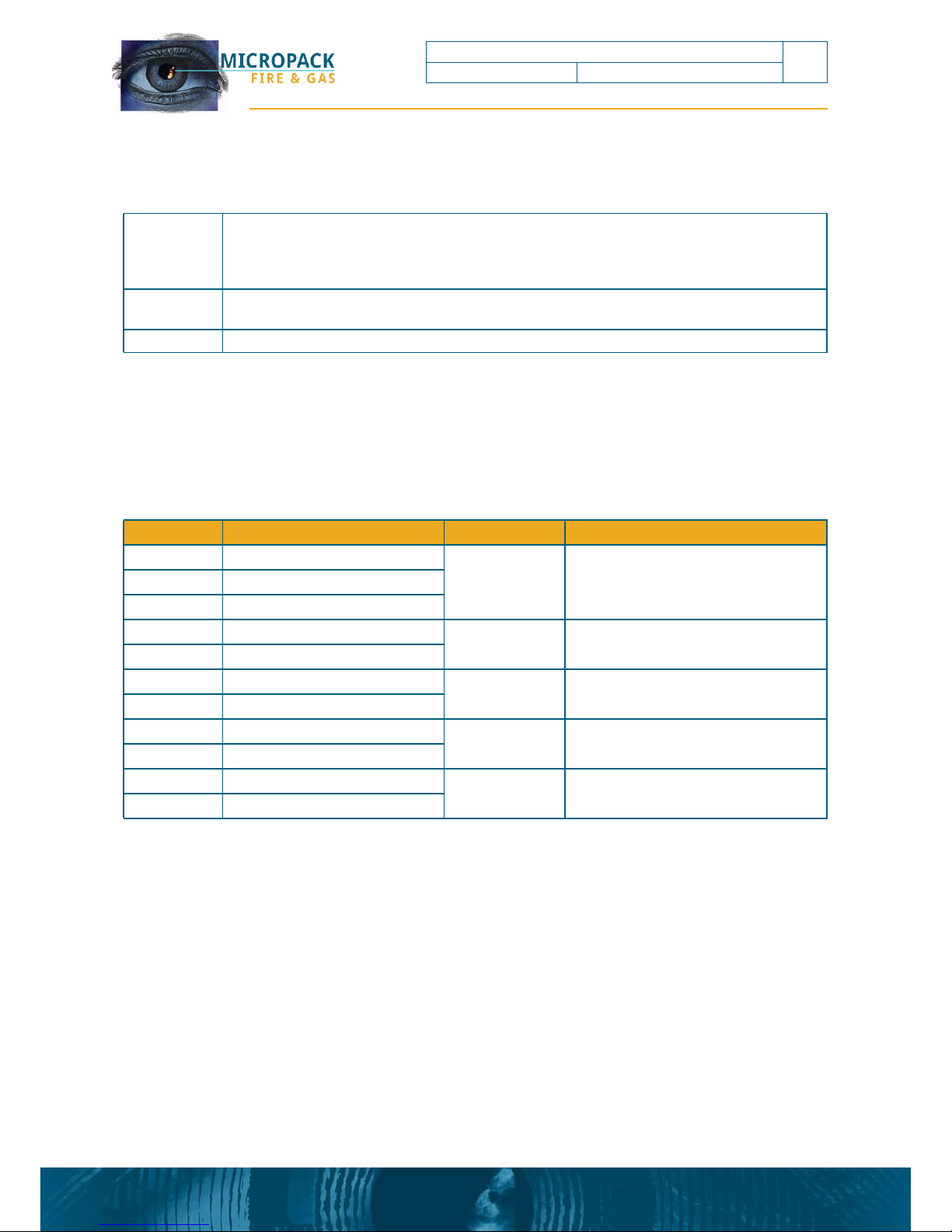
There are 4 video channels available, these have the following function:.
Table 2 Terminal Descriptions
This document is strictly private and confidential, reproduction without Micropack approval is prohibited. © Micropack Engineering Ltd, 2015
Terminal
Input
Terminal
Output Signal
1
+24V Supply Input
N/A
N/A
2
0V Supply Input
3
Do not connect
4
Channel 1 +V Video Input
BNC1
Channel 1 75R Video Output
5
Channel 1 -V Video Input
6
Channel 2 +V Video Input
BNC2
Channel 2 75R Video Output
7
Channel 2 -V Video Input
8
Channel 3 +V Video Input
BNC3
Channel 3 75R Video Output
9
Channel 3 -V Video Input
10
Channel 4 +V Video Input
BNC4
Channel 4 75R Video Output
11
Channel 4 -V Video Input
Notes
Consideration should be given to cable entry with sufficient space for looming.
When locating the equipment consideration should be given to maintenance access and
removal of the converter for repair or replacement
The mounting should be secure and vibration free
1 The electronics shall be protected form mechanical damage and external sources of EMI
such as X-rays, RFI and electrostatic discharge
2
Mount the converter.
VTP4 – Balanced Line To BNC Video Converter
8
Ref 2200.5005
Rev: 4.0
Page 9

3.4
Electrical Installation
The converter complies with the EMC requirements. In order to maintain compliance it is
essential the electrical installation be engineered correctly.
4
Maintenance and Testing
There are no specific maintenance requirements.
micropack.co.uk
Notes
Video cabling must be segregated from cables carrying high-speed data or high energy
and/or high frequency signals and other forms electrical interference.
The converter should only be fitted just prior to commissioning. Experience shows that the
sensitive electronics can be damaged due to cable testing operations (Insulation tests, etc)
1 Isolate all associated power supplies. Ensure that they remain OFF until required for
commissioning
2 The electronics should be removed prior to installation. The electronics shall be protected
from mechanical damage and external sources of EMI such as X-rays, RFI and electrostatic
discharge
3 Prepare the cable tails. The cable screens and twisted pairs should ideally be maintained
to within 1” (25mm) of the termination and insulated from contact with the enclosure or
any other local earth.
4 Where plastic junction boxes are used the cable screens (shield) should be maintained to
within 1” (25mm) of the termination and fully insulated
5 Where unscreened cables are used for panel wiring, then all cables must be suitably
twisted into pairs and video cables should be segregated from other signal sources
6 All cable screens (shield) should be connected to the local clean earth at the control
panel. The screens (and twisted pairs) should be maintained to within 1” (25mm) of the
terminations
7 Following installation completion, the cabling shall undergo full earthing and insulation
tests (with converter removed).
VTP4 – Balanced Line To BNC Video Converter
9
Ref 2200.5005
Rev: 4.0
Page 10

5
System Design Guidelines
5.1
Power Supply
The supply connects to terminal 1 for +24Vdc and terminal 2 for 0V. The system power supply
voltage and power distribution should be arranged such that on the longest cable run the
converter has a supply voltage of greater than 18V. To prevent video corruption the converter
and all equipment connected to the coaxial outputs should share a common 0V supply, the volt
drop on the 0V return must be kept to a minimum.
5.2
Balanced Line Video (twisted pair) Input
Connect the video twisted pair cable to one of the four video input connectors on the converter,
observing the correct + and - video polarity. All devices on the video transmission line, whether
drivers or receivers, should share a common 0V supply.
5.3
Video (Coaxial) Output
Connect the video coaxial cable to the one of the four BNC connectors on the converter. Care
should be taken when connecting to commercial video equipment as the Video braid is often
connected to the equipment 0V or earth. This can result in the supply current returning through
the coaxial cable screen, which may affect the video quality or potentially cause an earth fault. In
such cases care should be taken with the equipment power supply and cabling to reduce cable
volt drop to a minimum.
5.4
Earthing & Screening Requirements
It is important to ensure that the system is correctly connected to earth. Incorrect or poor
earthing can adversely affect system operation and may result in video corruption. The system
0V should be connected to a clean earth at only one point, generally this should be at the panel
power supply (or 0V bus bar). Even small differences in earth potentials can cause an earth fault
current to flow resulting in communication errors. Where this is not possible the system can
either be connected to a local clean earth so long as the maximum potential difference between
each earth does not exceed +/-7Vdc. Where earth fault monitoring is used care should be taken
to ensure that the system 0V to earth potential is not exceeded. All video cable screens should
be connected to the local clean earth at the control panel. The screens (and twisted pairs) should
be maintained to within 1” (25.4mm) of the terminations at the relay driver, within all junction
boxes and at the control panel. Where unscreened cables are used for panel wiring, then all
cables must be suitably twisted into pairs and video cables should be segregated from other all
signal sources.
This document is strictly private and confidential, reproduction without Micropack approval is prohibited. © Micropack Engineering Ltd, 2015
VTP4 – Balanced Line To BNC Video Converter
10
Ref 2200.5005
Rev: 4.0
Page 11
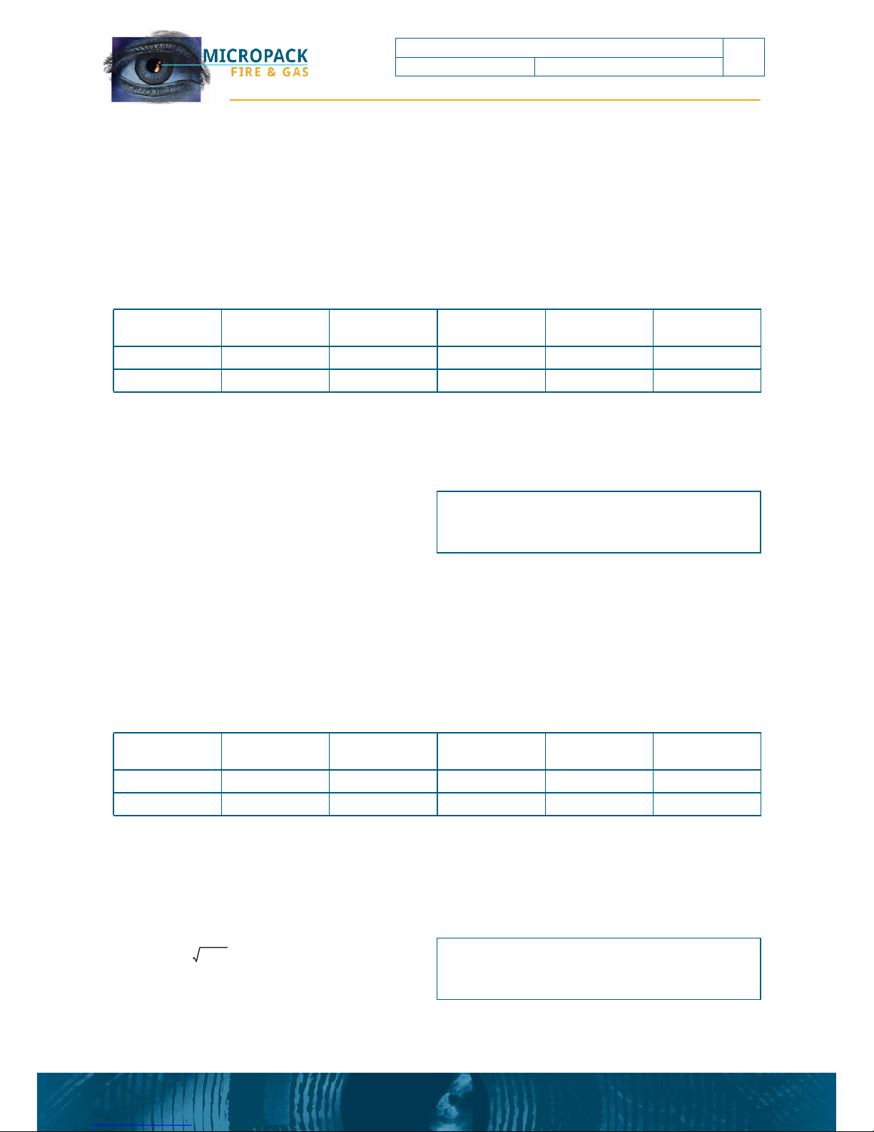
5.5
Coaxial Video Cable Selection
The video cable should be low loss (attenuation) 75R coaxial cable with a stranded conductor to
facilitate crimping, such as equivalent to RG59 or RG11, with the following characteristics:
Table 3: Video (Coaxial) Cable Characteristics
The maximum cable length is determined by the cable manufacturer’s attenuation specification,
typically 300m, as shown in the calculation below. Coaxial video cabling generally produces the
highest video quality and allows the use of commercial video switching equipment.
L
km
= Adb+ A
km
Equation 1 Video (Coaxial) Cable Length Calculation
5.6
Balanced Line Video (Twisted Pair) Cable Selection
The video cabling should be a twisted pair stranded cable with an overall screen. Where multicore cables are used then individual screened twisted pairs are recommended. The cable should
have the following characteristics:
Table 4: Video (Twisted Pair) Cable Characteristics
The maximum cable length is dependent on the cable manufacturers attenuation specification,
which is approximately proportional to conductor size. The characteristic impedance of a
transmission line is a function of the physical dimensions of the conductor and the permittivity of
the dielectric (the insulation), at high frequencies this is approximately equivalent to:
Zo(Ω) = ÷ L÷C
Equation 2 Characteristic Impedence Calculation
micropack.co.uk
L = Cable Inductance (mH)
C = Cable Capacitance (uF)
Zo = Characteristic Impedence (Ohms)
Cable
Characteristic
Characteristic
Impedence
Capacitance
Conductor
Resistance
Attenuation @
1MHz
Inductance
Nominal
150R
50nf/Km
- -
- -
- -
Absolute Limit
90R to 150R
100nf/Km
150R
6db
0.7mH/Km
A
db
= Attenuation Limit (db)
Am = Cable Attenuation per Kilometre (db/km)
L
km
= Cable length in Kilometres
Cable
Characteristic
Characteristic
Impedence
Capacitance
Conductor
Resistance
Attenuation @
1MHz
Inductance
Nominal
75R
62pf/m
- -
- -
- -
Absolute Limit
- -
75pf/m
<150R
6db
- -
VTP4 – Balanced Line To BNC Video Converter
11
Ref 2200.5005
Rev: 4.0
Page 12
6
Fault Finding
6.1
Live Video Images
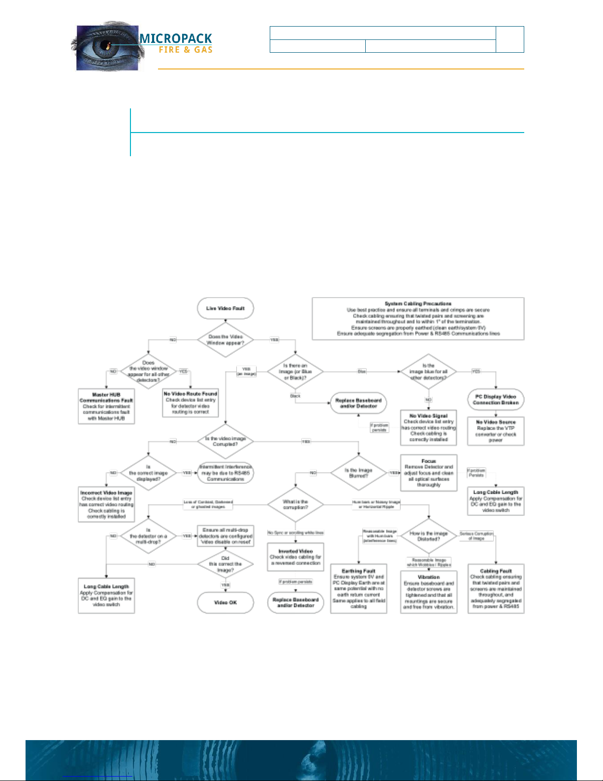
The live video signal suffers more potential problems than for RS485 communications because
the signal is an analogue transmission and available for operator scrutiny. The cabling is critical
to video image quality. Due to the nature of the video signal video corruption will appear
differently on each detector/installation. The following chart is intended as a guideline for
diagnosis of video problems.
Figure 3: Video Signal Diagnostic Chart
6.2
Replacement and Repair
The converter contains no user serviceable parts, or hardware configuration links to set.
This document is strictly private and confidential, reproduction without Micropack approval is prohibited. © Micropack Engineering Ltd, 2015
VTP4 – Balanced Line To BNC Video Converter
12
Ref 2200.5005
Rev: 4.0
Page 13
7
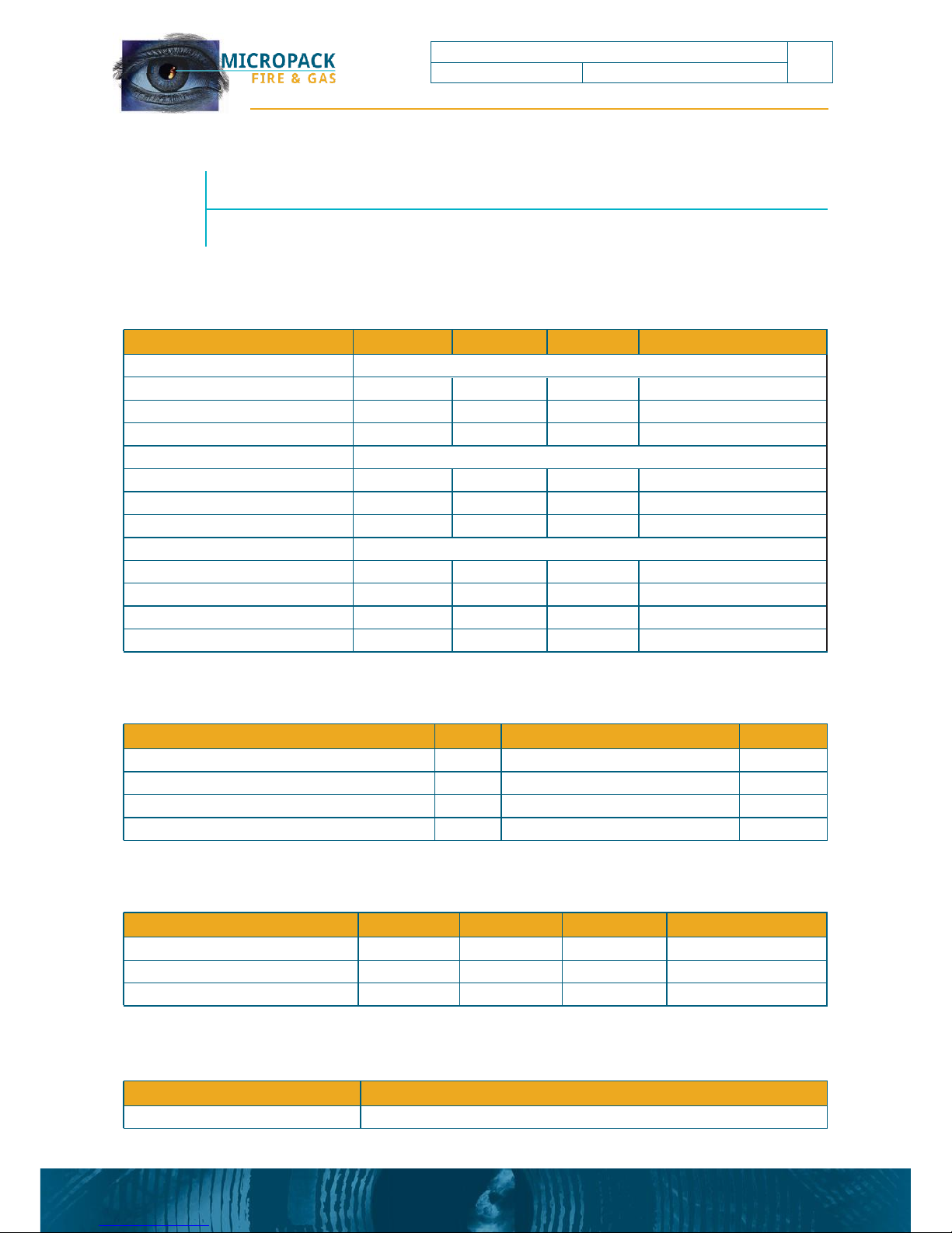
Technical Specification
7.1
Electrical Specification
7.2
Mechanical Specification
7.3
Environmental Specification
7.4
Certification and Approvals
micropack.co.uk
Parameter
Units
CE Certification
GEC: EN55022 & 082
Parameter
Units
Min
Max
Comment
Operating Ambient Temperature
°C
-20
+70
Storage Ambient Temperature
°C
-20
+80 Relative Humidity
% RH
5
95
Non Condensing
Parameter
Units
Min
Max
Overall Dimensions with DIN Rail Mounting
mm
108 Length x 78 width x 62 depth
Board Dimensions without DIN Rail mounting
mm
100 Length x 70 width
Shipping Weight
Kg
0.1
Baseboard Terminal Entries
mm2
2.5
Maximum
Parameter
Units
Min
Max
Comment
Power Supply
Supply Voltage
V
18
32
Inc. ripple
Supply Ripple
V 1V
Peak to Peak
Power Consumption
W
1.5
5
Balanced Line Video Receiver
150R Twisted Pair Cabling
Line Termination Resistor
R
- -
150
Built into each I/P
Differential Input Voltage
V
- - 2 Into 150R
Common Mode Input Range
V
-8
8
Coaxial Video Driver
75R Coaxial Cabling
Line Termination Resistor
R
- -
75
Driver Output Resistance
R
- -
75
Driver Output Voltage (loaded)
V
- - 1 Into 75R
Driver Fan Out
Unit loads
0
1
VTP4 – Balanced Line To BNC Video Converter
13
Ref 2200.5005
Rev: 4.0
Page 14
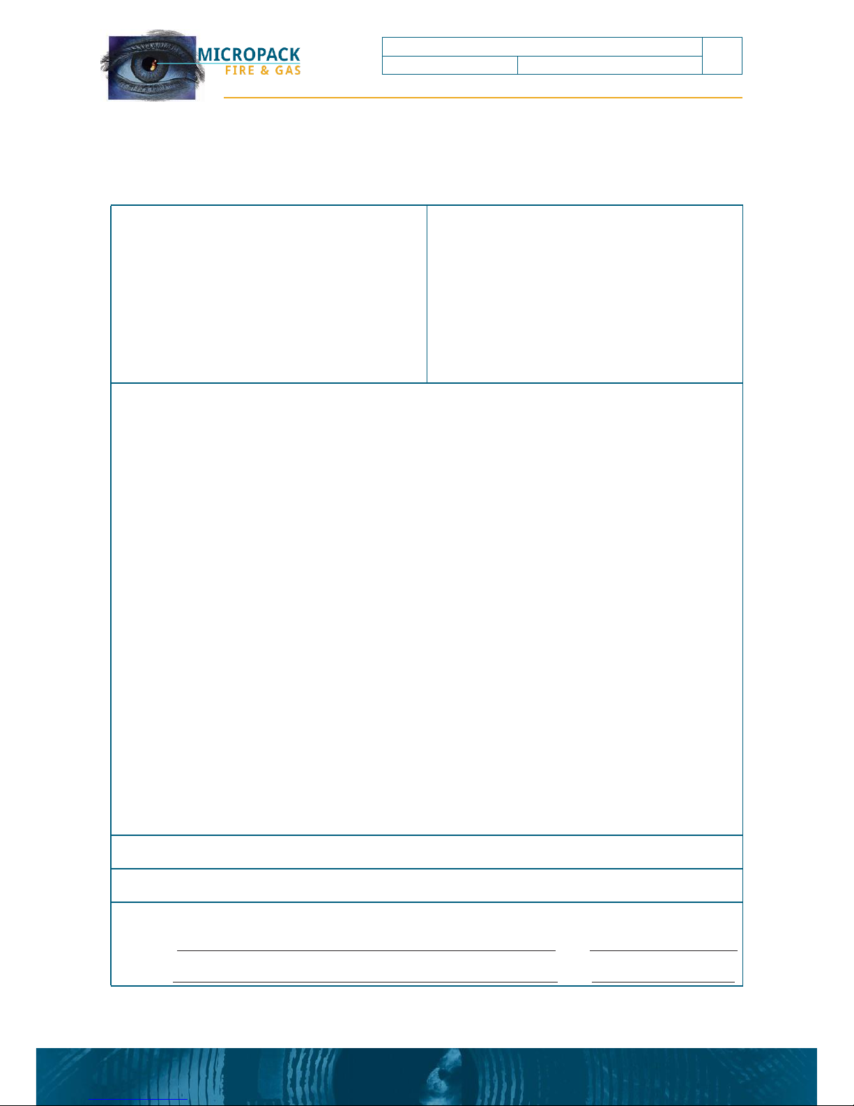
Appendix A -
Help us to help you
This document is strictly private and confidential, reproduction without Micropack approval is prohibited. © Micropack Engineering Ltd, 2015
TO:
QA Department
Micropack (Engineering) Limited
Fire Training Centre
Schoolhill, Portlethen
AB12 4RR
From:
Tel:
Fax:
Email:
I suggest the following corrections/changes be made to Section ……………
Marked up copies attached (as appropriate): Yes/No
Please inform me of the outcome of this change: Yes/No
For Micropack (Engineering) Limited :
Action by: Date:
Response:
Date:
VTP4 – Balanced Line To BNC Video Converter
14
Ref 2200.5005
Rev: 4.0
Page 15

micropack.co.uk
VTP4 – Balanced Line To BNC Video Converter
15
Ref 2200.5005
Rev: 4.0
Page 16

In the UK & Europe
MICROPACK (Engineering) Ltd
Fire Training Centre, Schoolhill,
Portlethen, Aberdeen AB12 4RR
In the Americas
MICROPACK Detection (Americas) Inc
1227 Lakecrest Court, Fort Collins,
Colorado, 80526
ISO9001:2008
Certified
Subject to modifications. © 2015 Micropack (Engineering) Ltd.
 Loading...