

Micropack FDS303 Technical Manual
FDS303
MULTI SPECTRUM IR
FLAME
DETECTOR
SAFETY & TECHNICAL MANUAL
Ref: 3303.0001
micropackfireandgas.com

2
FDS303 Safety and Technical Manual
Rev: 1.7 ECN: 4535 Ref: 3303.0001
FDS303 Flame Detector
This documen t is strictl y private an d confidential, reproduction withou t Micropack approval is pro hibited. © Micropack Enginee ring Ltd, 2018
HELP US TO HELP YOU
Every effort has been made to ensure the accuracy in the contents of our documents; however,
Micropack (Engineering) Ltd can assume no responsibility for any errors or omissions in our
documents or their consequences. This document has been processed through Micropack’s QA
procedures pertaining to ISO9001:2015 certification.
Micropack (Engineering) Ltd would greatly appreciate being informed of any errors or
omissions that may be found in our documents. To this end we include a form, given in
Appendix B, for you
to photocopy, complete and return to us so that we take the appropriate
action. Thank you.
CONTENTS
1
Introduction
4
1.1 Features 4
2
Safety Instructions
5
2.1
Specific conditions of use
5
2.2
Cautions
6
2.3
Important Safety Notices
6
2.4
EN 54-part 10 Limitation of use
7
3
Installation
8
3.1
Detector Enclosure
8
3.2
Mounting & Orientation
9
3.3
Wiring Procedure
11
3.3.1
0-20mA Output
12
3.3.2
Relay Output
13
3.3.3
Internal Inter-connections
14
3.4
Installation Checklist
15
3.4.1
Mechanical
15
3.4.2
Electrical
16
4
System Design Guidelines
17
4.1
Power Supply
17
4.2
Cable Selection
17
4.2.1 DC Power 17

3
FDS303 Safety and Technical Manual
Rev: 1.7 ECN: 4535 Ref: 3303.0001
FDS303 Flame Detector
This documen t is strictl y private an d confidential, reproduction withou t Micropack approval is pro hibited. © Micropack Enginee ring Ltd, 2018
5
Application Guidelines
19
5.1
Positioning Requirements
19
5.2
Detection Coverage
20
5.3
Exposure to Flare Radiation
20
5.4
Optical Contamination
20
5.5
Enclosed Areas
20
5.6
Detector Sensitivity
20
5.7
Detector Alarm Delay
20
6
Maintenance and Commissioning
22
6.1
Procedure
22
6.2
Functional Testing
24
7
Fault Finding
25
7.1
Removal of the Electronics
25
7.2
Replacement of the Electronics
25
7.3
Diagnostics
25
7.4
LED Indication
26
7.5
Power Fault
27
8
Technical Specification
28
8.1
Electrical Specification
28
8.2
Mechanical Specification
28
8.3
Environmental Specification
29
8.4
Certification and Approvals
29
8.5
Operating Specification
29
Appendix A
Acronyms, Terms & Abbreviations
30
Appendix B
Help us to help you 31
Appendix C
Field of View 32
Appendix D
FM Approval Performance Report
33
Appendix E
Offshore Certification 35
Appendix F
IEC 61508 Failure Rate Data 36

4
FDS303 Safety and Technical Manual
Rev: 1.7 ECN: 4535 Ref: 3303.0001
FDS303 Flame Detector
This documen t is strictl y private an d confidential, reproduction withou t Micropack approval is pro hibited. © Micropack Enginee ring Ltd, 2018
1
Introduction
This Safety and Technical Manual applies to FDS303 Hardware Version 1.0 and above.
The MICROPACK FDS303 is a flame detector that has unsurpassed false alarm
immunity for a Multi Spectrum IR flame detector.
The Micropack flame detection range are the safest and most advanced flame
detectors on the market today. Our worldwide installed base has proven that the
Micropack technology is robust, even in the harshest of environments.
FDS303 flame detectors identify flame using certified flame recognition software.
FM Approvals ensures that our flame recognition software is fit for purpose through
rigorous research and testing to a range of fires fuelled by different fuel types and
various potential false alarm stimuli.
The FDS303 has been designed for use in standalone operation.
1.1 Features
• The FDS303 has a 90o cone of vision with a range of 60 metres to a 0.1m2 pan
fire of heptane.
• Three detection sensitivity settings allowing the user to select the sensitivity that
is most suitable for their application.
• Superior false alarm immunity to common sources of unwanted alarms such as
Hot Process and Hot Work.
• Advanced optical verification test assuring readiness to perform when needed.
• Outputs include both relay contacts and 0-20mA.
• Separate termination chamber for ease of installation
• Certified Flame Simulator verifies operation from distances of 3 to 8 metres.
• FDS303 can operate via a standard 3 or 4 wire termination
• Microprocessor controlled heated optics increases resistance to moisture and
ice.

5
FDS303 Safety and Technical Manual
Rev: 1.7 ECN: 4535 Ref: 3303.0001
FDS303 Flame Detector
This documen t is strictl y private an d confidential, reproduction withou t Micropack approval is pro hibited. © Micropack Enginee ring Ltd, 2018
2
Safety Instructions
For the correct and effective use of this equipment, to maintain safety and avoid
hazards it is essential that you read and understand these instructions fully and act
accordingly BEFORE installing, operating or maintaining the equipment.
PAY ATTENTION TO ALL SAFETY WARNINGS AND CAUTIONS
2.1 Specific conditions of use
This equipment is certified and intended for use in potentially hazardous areas. Install and use
the equipment in accordance with the latest regulations.
The end user shall close any unused
entries using suitably certified blanking elements to maintain the housing’s type
of protection.
For European (ATEX) installations IEC/EN60079-14 ‘Electrical Installations in Hazardous Areas’ and
ICE/EN60079-17 ‘Inspection and Maintenance in Hazardous Areas’ should be strictly observed.
The Multispectrum IR flame detector type FDS303 is to be installed in places where there is a low
risk of mechanical damage.
For installations in North America the National Electrical Code (NEC) should be strictly observed.
In other countries the appropriate local or national regulations should be observed.
The equipment must be properly earthed to protect against electrical shock and minimise
electrical interference.
Do not drill holes in any housing or enclosure as this will invalidate the explosion protection.
Ensure that the enclosure lid is fully tightened and locked into position before energising the
equipment.
Do not open the enclosure in the presence of an explosive atmosphere.
All permits and proper site procedure and practices must be followed and the equipment must
be isolated from the power supply before opening the enclosure in the field.
Operators must be properly trained and aware of what actions to take in the event of a fire being
detected.
Cable to be used for installation is to be selected with a temperature rating of greater than 25
degrees Celsius above the maximum ambient temperature. The metric cable entries are fitted
with an internal stop. This will result in threads of the cable gland being visible. Do not over
tighten.

6
FDS303 Safety and Technical Manual
Rev: 1.7 ECN: 4535 Ref: 3303.0001
FDS303 Flame Detector
This documen t is strictl y private an d confidential, reproduction withou t Micropack approval is pro hibited. © Micropack Enginee ring Ltd, 2018
2.2 Cautions
Use only approved parts and accessories with this equipment.
Do not attempt to replace the window as the Sapphire and the front cover are individually
matched pairs to meet the stringent requirement of the Hazardous area certification.
The threaded portions of the detector are flame paths. These threads and the flame paths
are not to be repaired.
To maintain safety standards, commissioning and regular maintenance should be performed
by a qualified person.
2.3 Important Safety Notices
Pay attention to the guidelines given throughout this document.
If in any doubt about the instructions listed within this manual, then please contact Micropack
(Engineering) Ltd. Micropack (Engineering) Ltd takes no responsibility for installation and/or use
of its equipment if this it is not in accordance with the appropriate issue and/or amendment of
the manual. Micropack (Engineering) Ltd reserve the right to change or revise the information
contained herein without notice and without obligation to notify any person or organisation of
such action.
Only those parameters and configurations highlighted with the FM diamond ( ) have been
tested and approved by Factory Mutual.
Warning
Do not open the detector assembly in a hazardous area. The detector
contains limited
serviceable components and should only be opened by trained
personnel.
Caution
The wiring procedures in this manual are intended to ensure functionality of the device under
normal conditions. Due to the many variations in wiring codes and regulations, total compliance
to these ordinances cannot be guaranteed. Be certain that all wiring complies with the all local
ordinances. If in doubt, consult the authority having jurisdiction before wiring the system.
Installation must be done by trained personnel.
Caution
To prevent unwanted actuation or alarm, extinguishing devices must be inhibited/isolated prior
to performance testing or maintenance.
Detector Orientation
Detectors should be mounted with the earth stud directly below the lens.

7
FDS303 Safety and Technical Manual
Rev: 1.7 ECN: 4535 Ref: 3303.0001
FDS303 Flame Detector
This documen t is strictl y private an d confidential, reproduction withou t Micropack approval is pro hibited. © Micropack Enginee ring Ltd, 2018
Detector Positioning
Detectors should be positioned to provide the best unobstructed view of the area to be
protected.
The following factors should also be taken into consideration:
• Identify all high-risk fire ignition sources. Ensure that enough detectors are used to
adequately cover the hazardous area.
• Locate and position the detector so that the fire hazard(s) are within both the field of
view and detection range of the device.
• For best performance, the detector should be mounted on a rigid surface in a low
vibration area.
• Extremely dense fog or blizzard conditions could eventually block the vision of the
detector.
• For indoor applications, if dense smoke is expected to accumulate at the onset of a
fire, mount the detector on a side wall (approximately 1 to 2 metres) below the ceiling.
• The FDS303 has three sensitivity settings, which may be changed via a Micropack
application.
• The Detector carries out continuous internal hardware diagnostic testing to ensure
correct operation is relayed to the control system.
• The FDS303 is not designed to annunciate diagnostic failure of signal returns via
external wiring. Control systems and fire panels generally have fault monitoring for
such an eventuality.
2.4 EN 54-part 10 Limitation of use
The FDS303 is not approved for use in Oxygen-enriched atmospheres.
As the FDS303 responds to flame. It cannot be used in locations where flare stacks are within its
field of view or a reflected view is present without triggering alarms.
As the FDS303 responds to CO
2
Emissions of a flame the FDS303 cannot detect non-Hydrocarbon
fires, such as those using pure hydrogen, Silane and Sulphur as fuel.
The sensitivity of the FDS303 is reduced by obscurants such as smoke, fog and other
airborne particulates. The FDS303 may be blinded by extremely dense obscurants.
Arc welding should not take place within 10m of the FDS303 when using the highest
sensitivity setting.
8
FDS303 Safety and Technical Manual
Rev: 1.7 ECN: 4535 Ref: 3303.0001
FDS303 Flame Detector
This documen t is strictl y private an d confidential, reproduction withou t Micropack approval is pro hibited. © Micropack Enginee ring Ltd, 2018
3
Installation
The FDS303 design has been developed to allow simple installation. The detector comprises two
key components, the detector enclosure and the detector internal assembly. The detector
assembly located in the front of the enclosure should not be removed except by trained
personnel. Unauthorised removal or disassembly of the detector assembly will invalidate the
warranty. Only the rear end cap can be removed for terminal access.
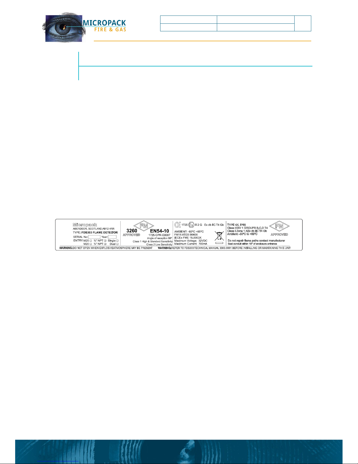
3.1 Detector Enclosure
The detector electronics are housed in an enclosure certified for use in hazardous areas. For the
exact certification and conditions of use see certification label on the device, or the example
drawing below:
The enclosure comprises the front window cover including the window Part Number
3303.8004, the rear enclosure cover Part Number 2301.6009, the enclosure body Part Number
2301.6007, certification rating label see above Part Number 3303.6006.01, and the mounting
bracket Part Number 2301.6012.
9
FDS303 Safety and Technical Manual
Rev: 1.7 ECN: 4535 Ref: 3303.0001
FDS303 Flame Detector
This documen t is strictl y private an d confidential, reproduction withou t Micropack approval is pro hibited. © Micropack Enginee ring Ltd, 2018
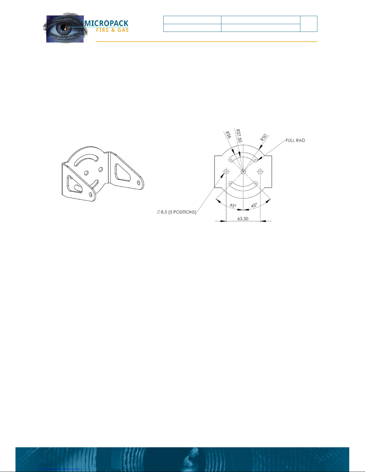
3.2 Mounting & Orientation
The mounting bracket allows the detector’s vertical orientation to be adjusted from 0 to 45° and
allows a horizontal rotation of +/-45° when mounted from above.
Figure 1: Detector Mounting Bracket

10
FDS303 Safety and Technical Manual
Rev: 1.7 ECN: 4535 Ref: 3303.0001
FDS303 Flame Detector
This documen t is strictl y private an d confidential, reproduction withou t Micropack approval is pro hibited. © Micropack Enginee ring Ltd, 2018
Figure 2: Ceiling Mount
Figure 3: Wall Mount
Firm, vibration free mountings are essential for trouble free operation of optical systems and
the
detector should be fixed to a rigid mounting. When mounting on a wall in this orientation
allow for the cable gland and cable as this may restrict the downward rotation of the detector.

11
FDS303 Safety and Technical Manual
Rev: 1.7 ECN: 4535 Ref: 3303.0001
FDS303 Flame Detector
This documen t is strictl y private an d confidential, reproduction withou t Micropack approval is pro hibited. © Micropack Enginee ring Ltd, 2018
3.3 Wiring Procedure
The wiring terminals are in the rear section of the detector enclosure and are accessible by
removal of the end cap.
The front section of the enclosure should only be accessed by trained personnel.
The terminal schematic detailed below shows the view looking inside the detector following
removal of the end cap.
Figure 4: Terminal Schematic
The detector has two types of alarm output available simultaneously
• 0-20mA (source non-isolated)
• Relay (Alarm & Fault)
Listed below are wiring options dependent on the functional requirements of the detector.

12
FDS303 Safety and Technical Manual
Rev: 1.7 ECN: 4535 Ref: 3303.0001
FDS303 Flame Detector
This documen t is strictl y private an d confidential, reproduction withou t Micropack approval is pro hibited. © Micropack Enginee ring Ltd, 2018
3.3.1 0-20mA Output
The following wiring connection diagram shows correct wiring of the detector when a 0-20mA
output is required.
Figure 5: 3 Wire Termination
Factory Fixed Values
Current Output
Event
0mA
Power/Detector Fault
1.5mA
Optical Fault
4mA
Healthy
18mA
Alarm
21mA
Over-range
Note:
The tolerance on the above outputs is +/- 0.3 mA dc current with a maximum loop
resistance of 500 ohms
 Loading...