


In the UK & Europe
MICROPACK (Engineering) Ltd
Fire Training Centre, Schoolhill,
Portlethen, Aberdeen AB12 4RR
Tel: +44 (0)1224 784055
Fax: +44 (0)1224 784056
Email: sales@micropack.co.uk
micropack.co.uk
In the Americas
MICROPACK Detection (Americas) Inc
1227 Lakecrest Court, Fort Collins,
Colorado, 80526
Tel: +1 970 377 2230
Fax: +1 970 377 2273
Email: info@micropackamericas.com
micropackamericas.com
Subject to modications. © 2015 Micropack (Engineering) Ltd.
ISO9001:2008
Certied
Mechanical Installation Guide
Listed below are installation guidelines for trouble
free operation of optical systems.
1. The detector should be attached to
comparatively rigid, vibration free mountings.
Glands should be torqued between 15 to 20 N•m
(11 to 15 lbf•ft).
2. The detector orientation shall be as detailed in
gure 1 below to ensure:
a. The IP rating of the detector is not affected.
b. The 120° horizontal eld of view is
maintained.
FDS300
VISUAL FLAME
DETECTOR
MICROPACK (Engineering) Ltd
Fire Training Centre, Schoolhill, Portlethen, Aberdeen AB12 4RR
T: +44 (0)1224 784055 E: info@micropack.co.uk micropack.co.uk
3. The front and rear enclosure covers shall be fully
screwed onto the enclosure body and the
grub screws tightened to ensure the hazardous
area certication is maintained.
4. In the case of an offshore vessel or platform, the
detector should ideally be placed facing inwards
towards the plant and with minimal view of the
horizon.
Status led must be directly
below the lens.
Ceiling Mount
Wall Mount
Figure 1: FDS300 Orientation
Ref - 2401.6003 Rev - 2.0
In the UK & Europe
MICROPACK (Engineering) Ltd
Fire Training Centre, Schoolhill,
Portlethen, Aberdeen AB12 4RR
Tel: +44 (0)1224 784055
Fax: +44 (0)1224 784056
Email: sales@micropack.co.uk
micropack.co.uk
In the Americas
MICROPACK Detection (Americas) Inc
1227 Lakecrest Court, Fort Collins,
Colorado, 80526
Tel: +1 970 377 2230
Fax: +1 970 377 2273
Email: info@micropackamericas.com
micropackamericas.com
Subject to modications. © 2015 Micropack (Engineering) Ltd.
ISO9001:2008
Certied
Electrical Installation Guide
The wiring terminals are located in the rear section
of the detector enclosure and are accessible by
removal of the end cap.
1. The detector enclosure is to be connected to
a local earth and the detector cable screens
(shields) should be cut back to the crotch and
not terminated within the detector.
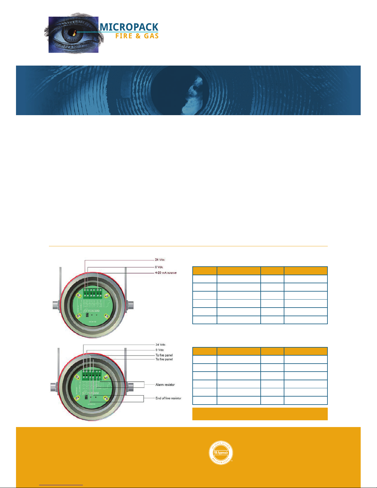
2. The terminal schematic (gure 2) detailed below
shows the view looking inside the detector
following removal of the end cap.
FDS300
VISUAL FLAME
DETECTOR
3. The detector can be congured for two types of
alarm output:
a. 4-20mA current source
b. Standard Relay (Alarm & Fault)
a. 4-20mA Conguration
b. Standard Relay Conguration
Figure 2: FDS300 Orientation
Terminal Description Terminal Description
1 +24Vdc 2 0Vdc
3 Not Used 4 Not Used
5 4-20mA Signal 6 0Vdc
7 +24Vdc 8 0Vdc
9 Not Used 10 Not Used
11 Not Used 12 Not Used
Terminal Description Terminal Description
1 +24Vdc 2 0Vdc
3 To Fire Panel 4 To Fire Panel
5 Not Used 6 Not Used
7 +24Vdc 8 0Vdc
9 EOL Resistor 10 EOL Resistor
11 Alarm Resistor 12 Alarm Resistor
If further details are required, full wiring details are available
from: FDS300 SAFETY & TECHNICAL MANUAL – Ref: 2401.6000
Ref - 2401.6003 Rev - 2.0
 Loading...