

Page 1
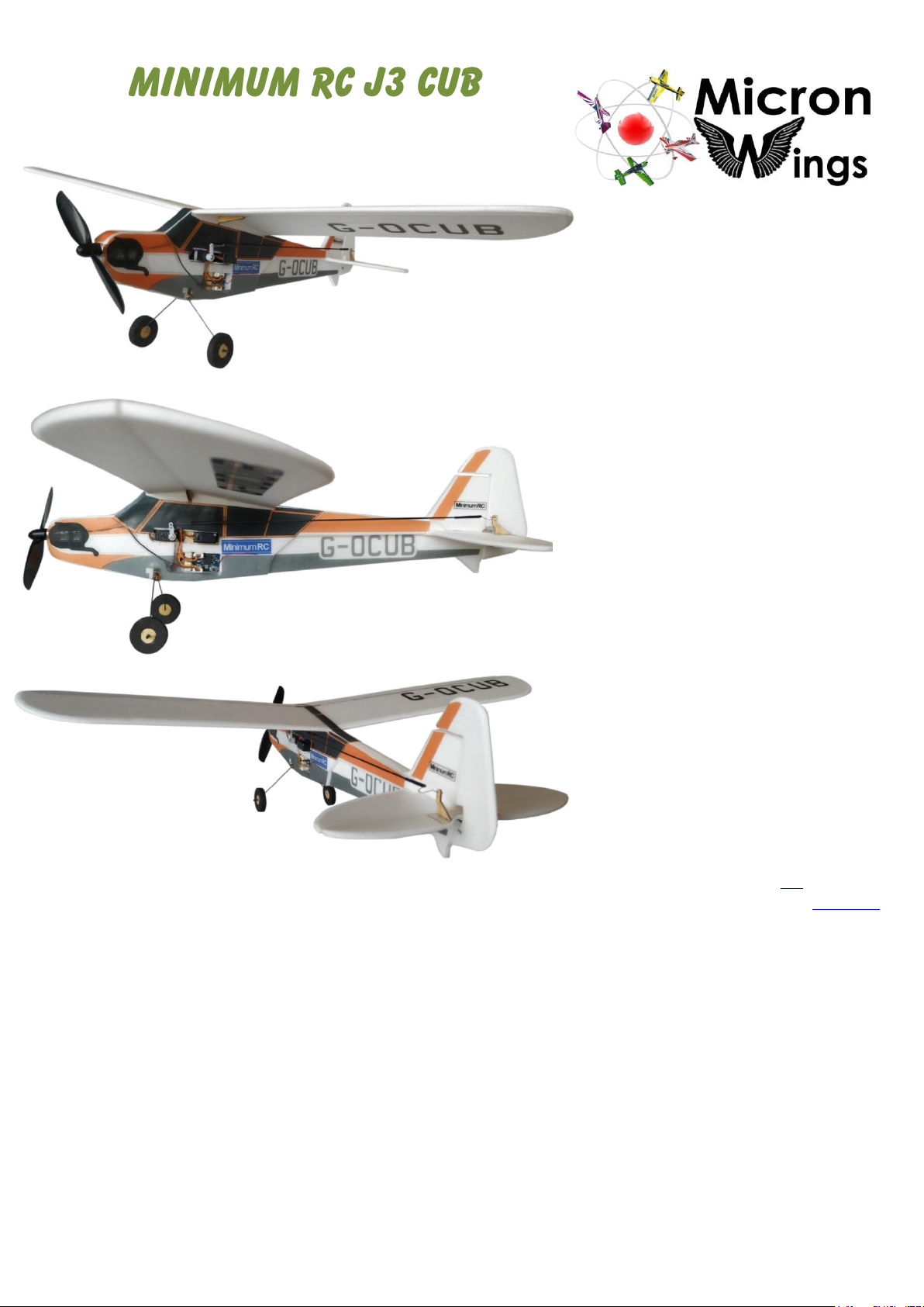
(MicronWings Deluxe Version)
Specifications
Wingspan: 40.5cm
Flying Weight: 28 grams (with battery)
Channels: 3
Suggested Receiver: 4Ch Micro
Motor: 7mm Brushed Direct Drive
Airframe Kit
(Included Contents)
* Airframe Parts Sheets (Depron)
* Airframe Bracing Parts (Plywood)
* Motor and Propeller
* Control Linkages + Pushrods
* Sandpaper Sheet
* Decal Stickers
* Undercarriage
Needed to Complete
* Micro Receiver with 2A ESC
* Two Micro Servos (5320 Servos)
* Transmitter and Battery Charger
* Battery (130 to 160mah 1S)
* Soldering Iron with Fine Tip
* Epoxy Glue
* UHU Por Expanded Polystyrene Glue
* Micro Screwdriver
* Micro Drill Set (less than 1mm diam)
* Hobby Knife
* Blenderm Hinge Tape (Link)
* Modelling Tape - Optional (Product Link)
* Ruler (metal preferred)
* Plyer snips or side cutters
* Fine tip scissors
* Tweezers
MicronWings sells this deluxe version of the J3 Cub under
license from the manufacturer, Minimum RC. The
MicronWings Deluxe Version features an airframe cut from
3mm Depron as well as improved design features and the
addition of control surface bracing mounts.
The J3 Cub is small enough to be flown indoors (sports
stadium area) and is also capable of being flown outside on
a calm day. With a direct drive 7mm x 20mm brushed
motor, this model can cruise adequately at just half throttle
and at full throttle it can even perform loops.
Page 2
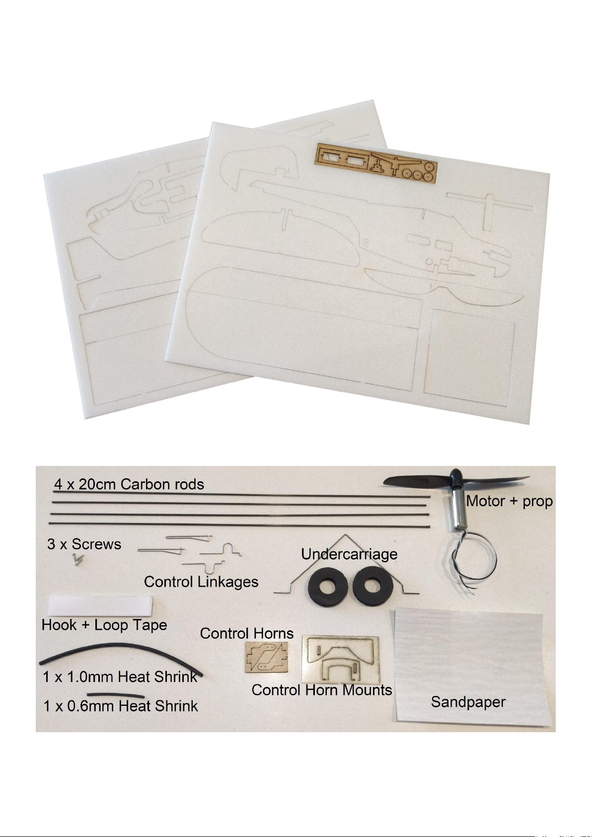
Included Parts - Your kit includes the following parts.
Depron parts sheets and wooden parts sheet
Assorted Parts
Page 3
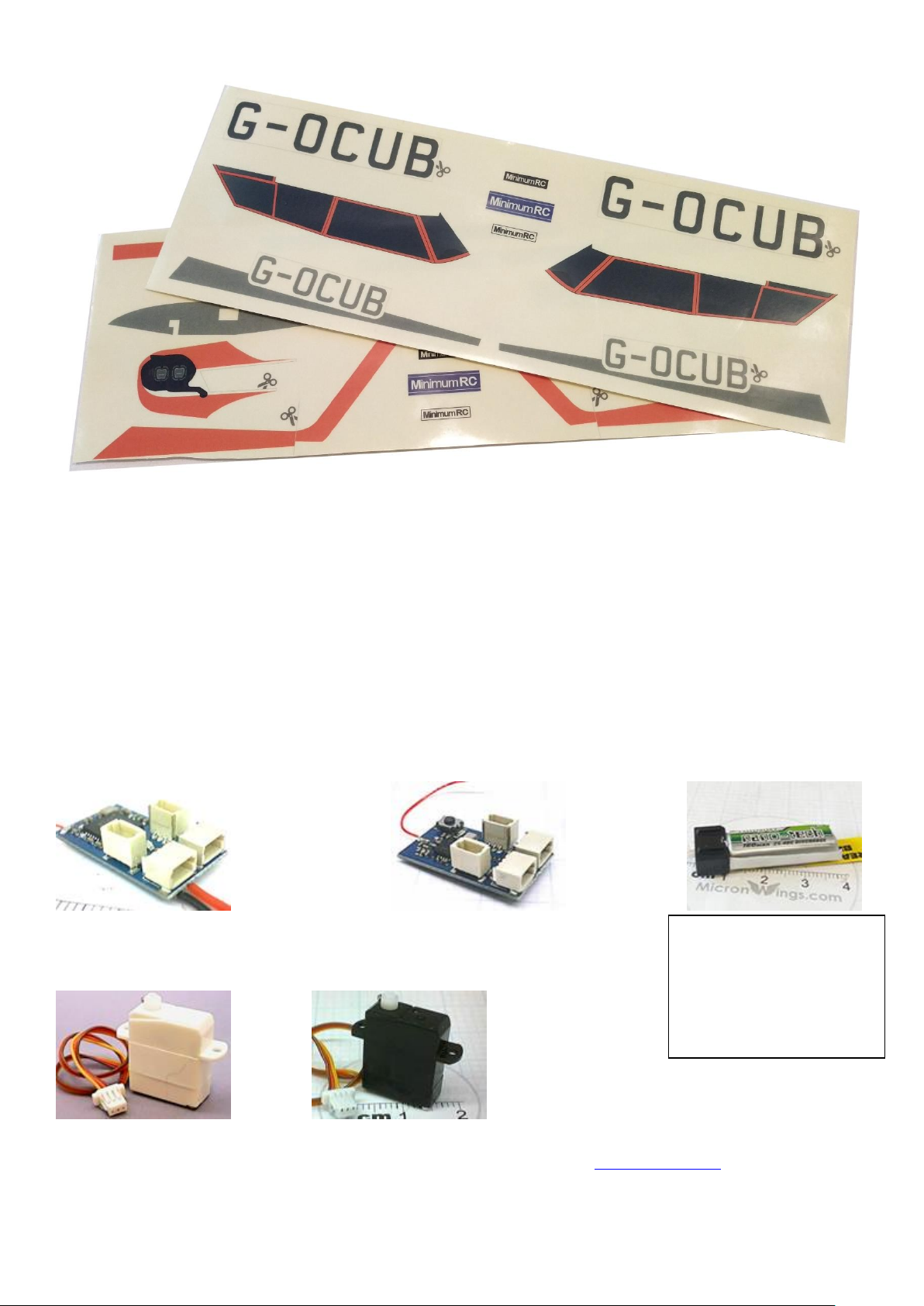
Decal Stickers
Before You Start
This Minimum RC plane is supplied in kit form and needs to be built. You will need intermediate
level model building skills to complete this kit. You may also require micro soldering skills to solder
the battery leads and motor leads to your chosen receiver.
Receivers , Servos and Battery
You may choose to fit any micro receiver and servos you wish in this kit. However, the kit has
been specifically designed for any of the following receivers and servos.
4ch DSMX/2 Rx with 2A ES 4ch FRSky Rx with 2A ESC Nano-Tech 160Mah Battery
Servo 5320 White SH Servo 5320 Black SH
Or if using a different receiver, please use a suitable 5320 servo (Servo page link)
This is the recommended
battery. Nanotech brand or
similar generic brand –35 to
40C. Australian customers
can purchase these from
MicronWings
Page 4
Control System Configuration
You will need a transmitter which has the capability to change servo direction. Most modern
transmitters have this function in a menu on the transmitter.
Glues
This kit requires foam glue and Epoxy glue.
* Use foam glue to glue all foam parts together.
* Use Epoxy glue for gluing the motor in place. Epoxy glue is required for this as the motor
becomes hot and Epoxy glue will withstand heat better than foam glue.
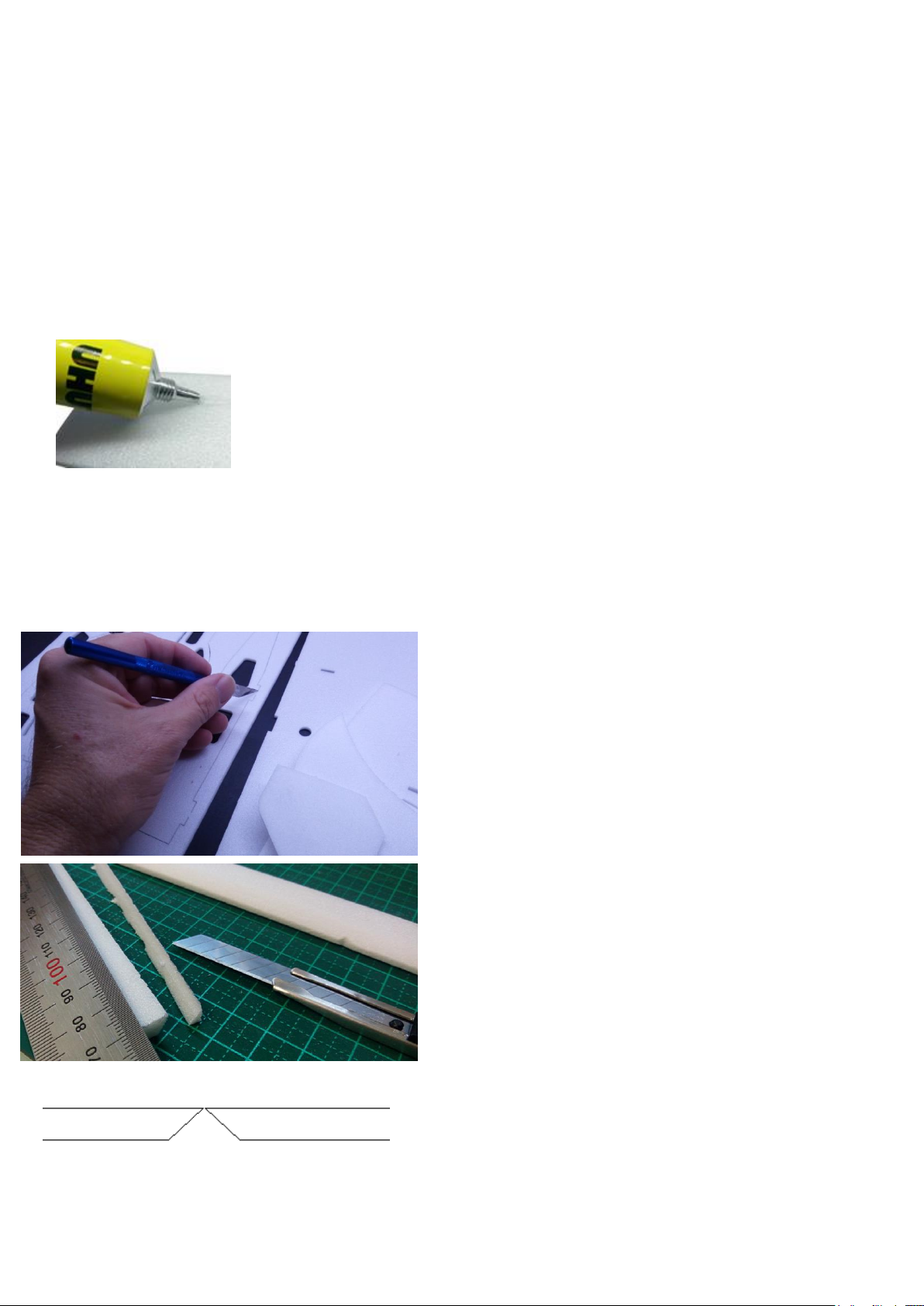
Recommended Foam Glue – UHU Por Expanded Polystyrene
Build Instructions
Cut the parts from the Depron sheets and cut out
any pieces from the airframe which need to be
removed such as the circle holes, receiver and
battery bay cutouts and so on.
The following control surfaces need to have a bevel
cut into one edge.
* Elevator
* Rudder
To do this, place a metal ruler on top of the foam
surface and align with the edge to be trimmed. Use
a hobby knife with a new blade and angle it at 30
degrees to cut back under the ruler and cut the
bevel out of the control surface. Do this on both the
control surface and where it connects to the airframe.
Page 5
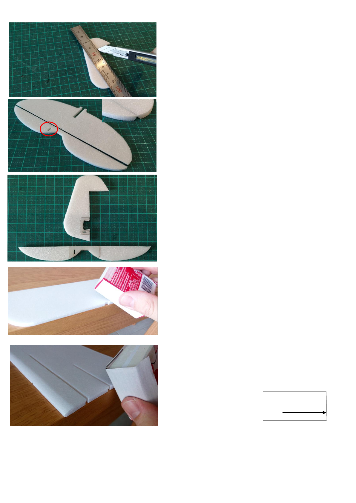
Cut the vertical stabilizer from this side as shown
here. It will be hinged on the upper surface side
(right hand side) and this is the side the control horn
will attach too as well.
Undercut the tail surface as shown here as well with
the control horn slot on the left-hand side.
Use UHU Por Expanded Polystyrene glue to glue the
control horn mounts in place as shown here. Don’t
use too much glue, only a small amount is needed.
Next prepare for sanding.
Always sand outside in an open area and don’t
breathe in the sanding dust. Use a sanding block or
a match box to wrap the sand paper around.
Sand the edges of the control surfaces round. Sand
the tail surfaces and the wings. But for the wings,
don’t sand a round curve on the edge where they
join the airframe. Also, for the wings, sand more
curve on the top side than the bottom.
The top side has the half-cut grooves.
Sanding the wings on the edge of a table will
support the foam as you sand it.
Finally, where the wings attach to the fuselage, sand
a very slight bevel sloping back on the top. This will
allow the wings to have
upward dihedral when
attached to the body. Just a
few degrees sanded back is
good.
About 2 degrees
Page 6
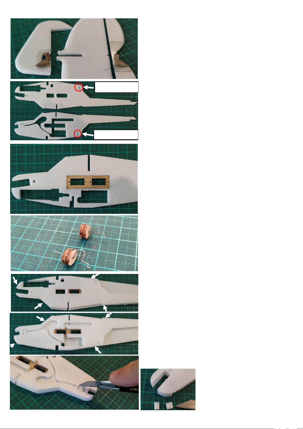
After sanding, glue the control horns in place.
Make note of which side is left and right.
The left side has a cut-out for a receiver.
The right side has a cut out for a battery.
Glue the wooden servo mount in place in the central
fuselage piece and make sure it is centered in the
foam sheet.
While the fuselage servo mount is drying, work on
the wheels. Glue the two sets of hubs together and
use the control linkages to get the center holes lined
up. Set aside and allow to dry while you continue
with the fuselage.
Glue in place the two side pieces. For these, just
apply the glue to the side piece and spread it out
thin. Then align it with the main centre piece of the
fuselage.
If you place it on very gently without pressing it
down, it will be able to be moved a little to get it in
the correct position. Note your alignment points
shown by the arrows. Make sure the pieces are flush
here.
Once it is positioned correctly, press firmly to set it
in place.
Cut out this piece which is
used to hold the left hand side
frame in shape while gluing.
Left hand side
Right hand side
Page 7

Screw the three screws into the undercarriage
mount and leave the heads sticking out just enough
so the undercarriage fits in neatly under them.
Attach the undercarriage as shown here. Glue it in
place with Epoxy glue and ensure it is level.
This MicronWings version of the J3 Cub uses a wing
support rod, so cut this part off the wing mount.
Glue the wing mount in place with Epoxy glue and
make sure it is square with the airframe sides.
Also check the upward angle is equal on both sides.
Allow these parts to completely dry.
Glue the tires onto the hubs.
Page 8
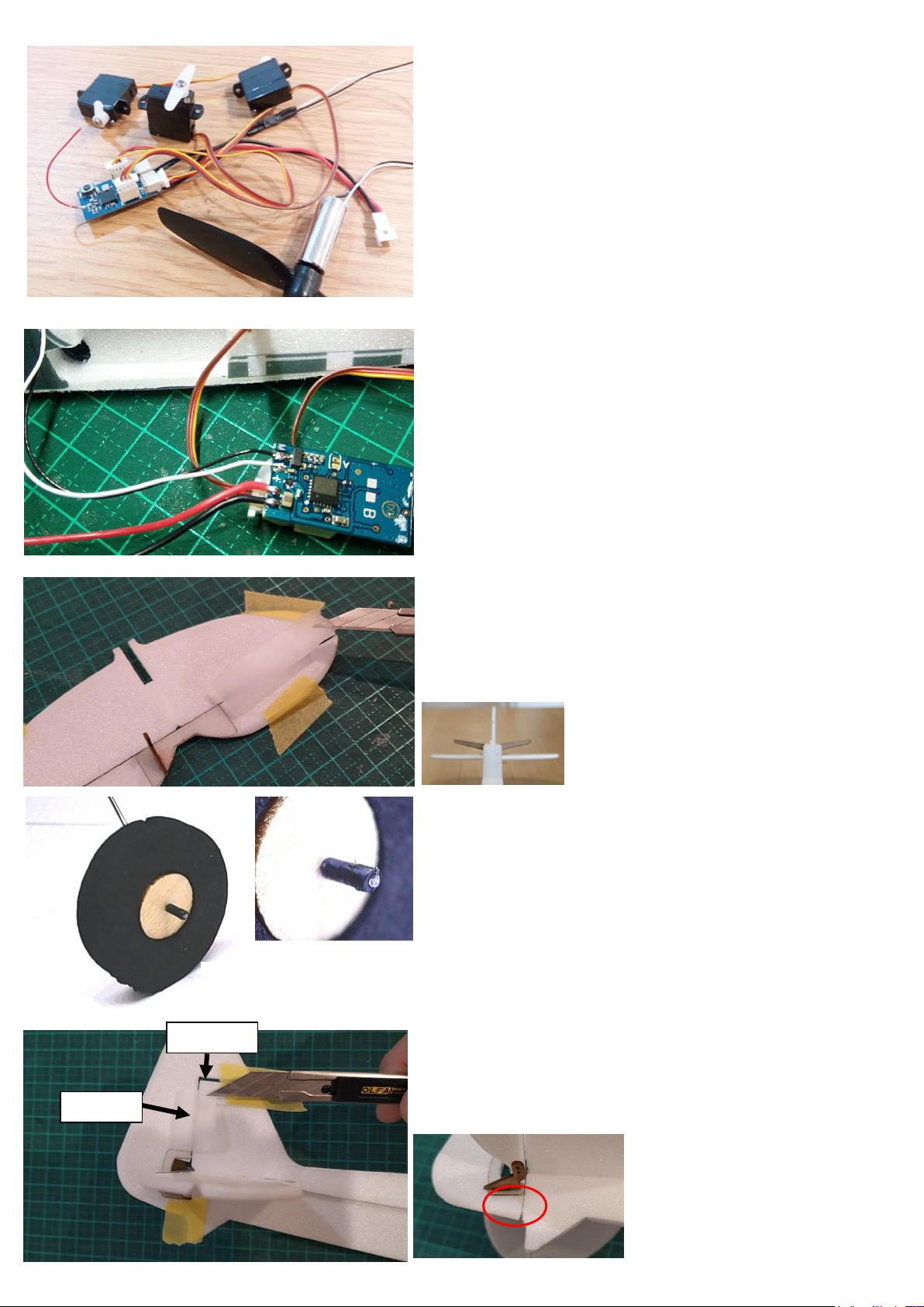
While the airframe and wheels are drying, it’s a good
chance to connect up all your electronics and check
everything works properly.
Check all your trims and mixing on your transmitter
are set these to neutral.
If using the recommended receiver, connect the red
and black battery wires as shown here. For the
motor, note that the white wire is towards the inside
and the black wire on the outside. But don’t solder
the motor wires as yet.
Tape the horizontal stabilizer and elevator to a flat
surface with modelling tape to leave 0.5mm gap
between them. Then, use Blenderm hinge tape on
either side to attach the elevator surface.
Glue the horizontal stabilizer in
place and check it is level.
Allow to dry.
Use a 0.5mm diameter micro drill bit to drill out the
holes in the wheels so they spin freely on the
undercarriage.
Attach the wheels and use 4mm piece of the smaller
heat shrink tube (0.6mm tube) to keep the wheel in
place. Heat the heat shrink with a soldering iron tip
to shrink it.
Tape the vertical stabilizer in place with modelling
tape as shown here. Leave a gap of 0.5mm at the
back and 1mm at the top
Also attach the vertical
stabilizer control surface
here with a thin piece of
Blenderm hinge tape.
0.5mm
1mm
Page 9
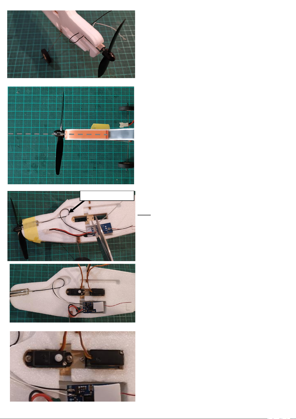
Glue the motor in place with Epoxy glue. Feed one
motor wire through the hole in the right hand side of
the fuselage to the left hand side where both the
wires will run down to the receiver.
Give the motor a slight amount of right thrust as
shown here. A piece of modelling tape around the
nose will hold the motor firm in place while the glue
dries.
Sit the receiver in the receiver bay upside down.
Loop the motor wires in the cavity as shown so they
don’t reach the back of the cavity. Then trim the
motor wires to length.
The cavity allows the wires to be drawn out or
pushed further back into it as required when
positioning the receiver.
Solder motor wires to receiver.
Feed the battery connector through hole to the right
hand side. Attach double sided tape to the bottom of
the receiver.
Looking from the left hand side of the airframe the
servos should be installed exactly like this.
For the front servo, the servo wire is laid flat on top
of the servo case and comes back through to the
right hand side where the receiver is.
Set the wire flat on the servo case before inserting it
into the slot.
Position wires here
Page 10
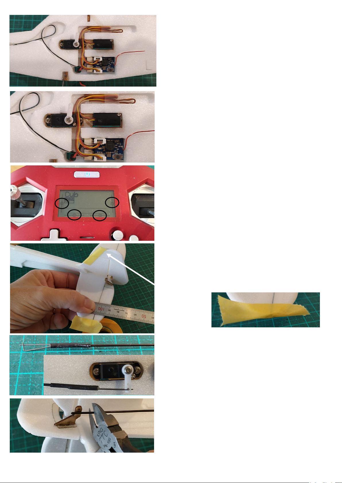
Mount the receiver and connect the servos.
Power up the RC system and check your transmitter
trims are centered. Then check servo travel direction
and reverse if needed.
Note: If you prefer to fly with ailerons instead of
rudder, you can plug the rudder servo into the
aileron port on the receiver.
Use small strips of Blenderm tape to secure the
motor wires in place. Also route your servo wires as
shown here and use Blenderm tape at a few
locations to hold them in the cavity.
The servo wires and the motor wires will be covered
up by the decals later.
Power up your transmitter and receiver. Check all
servo arms are centered and that all trims on your
transmitter are also centered. Power down
transmitter and receiver.
Hold the control surfaces flush with a ruler and then
apply some modelling or masking tape on the control
surfaces to ensure they are held straight while you
connect the control linkages.
Bend the tape over to the bottom of the surface to
make a U shape.
Apply a small amount of UHU Por Expanded
Polystyrene glue to the end of the pushrod and
attach the control linkage. This clip type linkage will
connect to the servo arm. Apply heat with a
soldering iron and shrink the heat shrink. The glue in
the joint will heat and set hard to make the joint
stronger.
Trim the pushrods to be about 5mm short of the
hole in the control horn.
Page 11
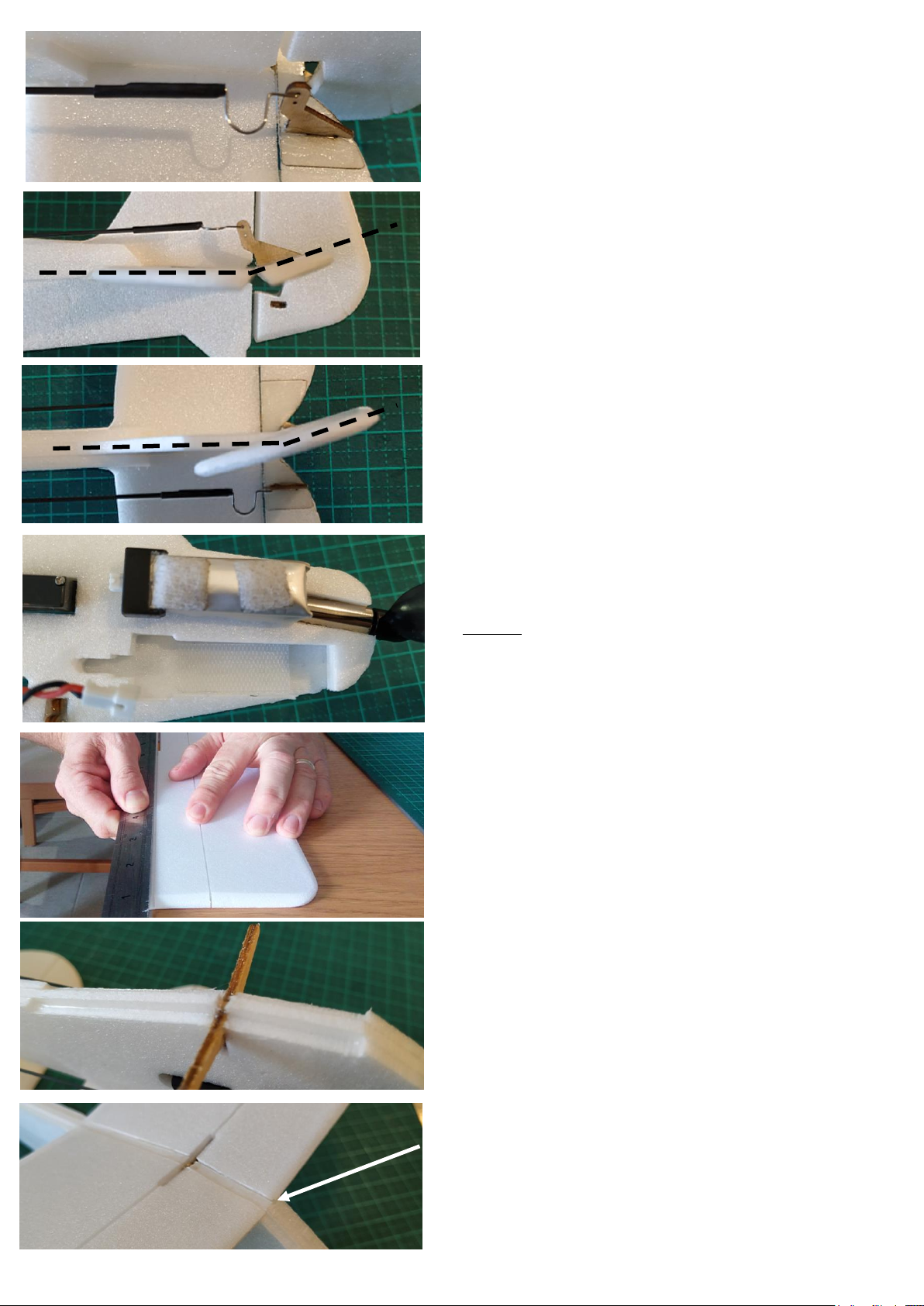
Attach the control linkages to the control horns.
* Remove the tape holding the control surfaces
before powering on your system and testing your
control surface movement.
You will most likely need to dial down the throws on
your control surfaces. Use your transmitter’s settings
to reduce the travel movement of the servos.
These images show the maximum throws that each
surface should have.
Cut a 20mm long piece from the hook and loop tape
and stick one side into the battery bay as shown
here.
Cut smaller pieces to attach to your battery. This will
ensure that the piece attached to the airframe will
not be pulled away from the airframe when you
remove the battery.
Next bend the wings along the half cut line. Support
on the edge of a table and use a ruler to apply even
force along the wing. Bend downwards to about a 30
degrees angle till you hear the foam crack a little.
Apply UHU Por Expanded Polystyrene glue to the
wing seat mounts on the fuselage as well as the
wooden wing mount. Also apply the glue to the ends
of the wings which attach to the fuselage.
For this, use a very small amount of glue on all
surfaces and scrape off any excess. Allow to dry for
5 minutes and then attach the wings.
When attaching the wings ensure they are as far
forward as possible in the gap so they are flush up
against this part.
Allow the glue to set for about 15 minutes.
Page 12
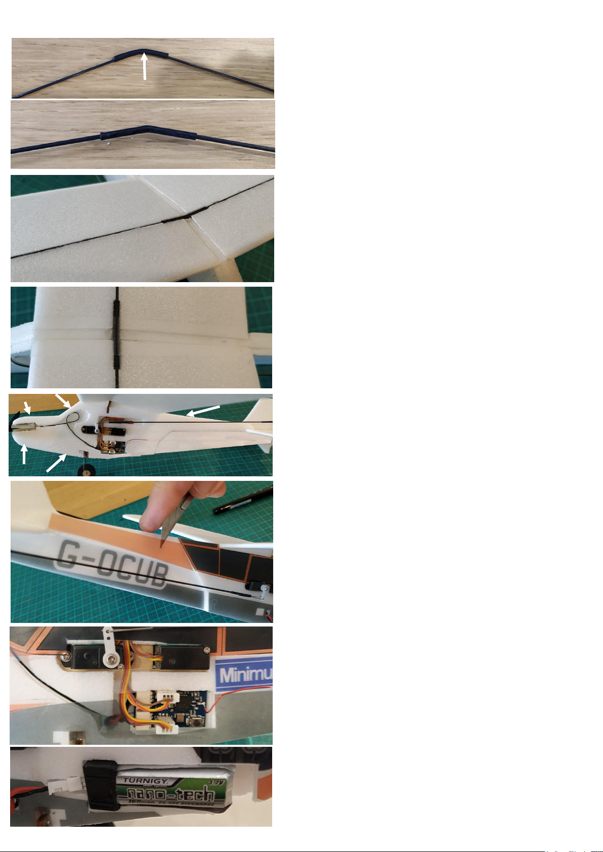
Cut a piece of heat shrink 20mm long and use it to
join the two carbon wing braces. Bend at an angle to
check that the piece of heat shrink is centered.
For this joint don’t use any glue.
This is what the joint should look like after shrinking
the heat shrink.
Apply a small amount of glue to the under side of
the carbon rods. Don’t wait for the glue to dry press them down into the grooves in the top of the
wings. You may need to bend the wings a little to
press the rods in. Ensure they are flush with the top
of the wing surface and quickly scrape off any
excess glue with a scrap piece of Depron.
Run a strip of Blenderm tape along the wing root to
give extra strength.
Before attaching the decals, sand these edge
surfaces flat. The long thin decals will attach to
these surfaces.
Looks almost done but as always, decorating takes
the most time. Take your time applying the decals
for a nice finish.
Cut the decals out of the sheets and attach as shown
on the next page. The Decal stickers also cover up
the gaps which have the motor wires and servo
wires inlayed.
It’s a good idea to use a hobby knife to set the
decals in position instead of your fingers. This makes
it easier and improves accuracy.
For the receiver, battery bay, undercarriage and
servos, you will also need to trim the decals to fit
around these parts. Remove the rudder pushrod
from the servo arm to make attaching the decals
easier.
Page 13
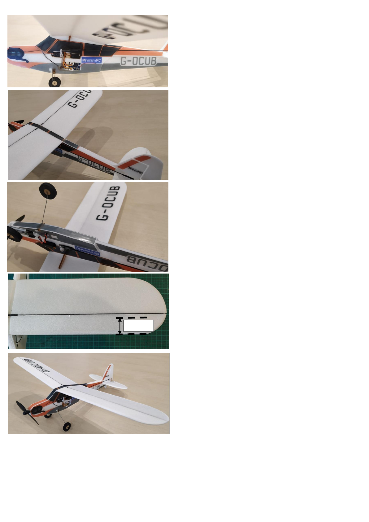
Attach decals as shown here.
Mount the battery and check your balance point. It
should be about 20mm from the leading edge of the
wings.
Your finished aircraft should look very similar to this.
If it doesn’t, read back over the steps on the
previous pages.
20mm
Page 14
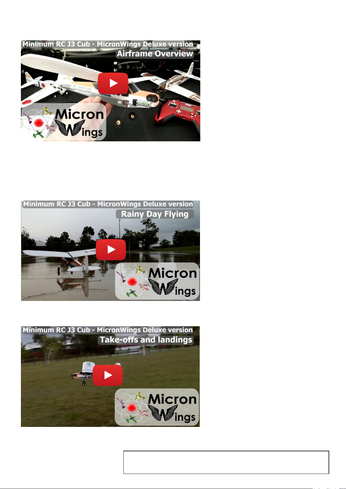
Overview Video
A quick look at the airframe and it’s features.
Flight Video (Rainy Day Flying)
A flight in the local park with take-offs and landings.
Flight Video (Take-offs and Landings)
Copyright © MicronWings 2019: All rights reserved.
This manual is for personal use only. No unauthorized copying or digital distributing permitted
without permission from MicronWings.
 Loading...