

Page 1

NetFRAME
®
6500 Server
Quick Start Guide
Page 2

i
...............
Table of Contents
Copyright Notice .................... .................................................. ii
Trademark Notice ............................ ................................. ii
Limitation of Liability .............. ......................................... .. ii
Life Support .................................................................. .... ii
Welcome........................................................ 3
Technical Reference Manual ........................................ ........... 3
Manual Conventions ................................................................ 4
Special Text ...................................................................... 4
System Features........................................... 5
Pedestal/Rack Chassis............................................................ 6
Front Panel View ............................................................ .. 6
Front Control Panel View............................... ................... 7
Back Panel View............................................................... 8
Rack Optimized Chassis................. ......................................... 9
Front Panel View ............................................................ .. 9
Front Control Panel View............................... ................. 10
Back Panel View............................................................. 11
Front Control Panel Descriptions ......................................... .. 12
System Board Features ............................. 15
System Board Components ................. .................................. 16
Memory Specifications ........................................................... 19
Memory Bank Order ........................................................ 20
Processor Specifications ........................................................ 21
System Board Jumpers .......................................................... 22
Page 3

Copyright Notice
ii
...................................................................
COPYRIGHT NOTICE
Copyright 2002 MicronPC, LLC. All rights reserved. The information in this document is subject to change without
prior notice in order to improve reliability, design, and function and does not represent a commitment on the part of
the manufacturer. In no event will the manufacturer or seller of a MicronPC product be liable for direct, indirect,
special, incidental, or consequential damages arising out of the use or inability to use the product or
documentation, even if advised of the possibility of such damages. Except as stated in the applicable MicronPC,
LLC limited warranty, MicronPC and its affiliates, by this manual, make no other express warranties and all other
warranties, including, without limitation: THE IMPLIED WARRANTY OF MERCHANTABILITY AND THE IMPLIED
WARRANTY OF FITNESS FOR A PARTICULAR PURPOSE ARE HEREBY DISCLAIMED.
This document contains proprietary information that is protected by copyright. No part of this document may be
photocopied, reproduced, or translated to another language without the prior written consent of:
MicronPC, LLC
906 E. Karcher Road, Nampa, Idaho 83687
Trademark Notice
Windows, Windows NT, MS-DOS, and Microsoft are registered trademarks of Microsoft Corporation. Pentium and
Xeon are trademarks or registered trademarks of Intel Corporation. Other product names mentioned herein are
used for identification purposes only and may be trademarks and/or registered trademarks of their respective
companies.
Limitation of Liability
While reasonable efforts have been made to ensure the accuracy of this manual, the manufacturer and seller assume
no liability resulting from errors or omissions in this manual or from the use of the information contained herein.
Life Support
Products sold by MicronPC are not authorized for use as critical components in medical devices or systems or in
nuclear facilities without the express written approval of the Chief Executive Officer of MicronPC.
MAS001424-00, MAL, 09-05-2002
Page 4

1-3
.....
...................................
W
ELCOME
1
Thank you for buying a MicronPC NetFRAME 6500 server. This
Quick Start Guide
provides
information to help you quickly get started using your new server.
................................................................ .
TECHNICAL REFERENCE MANUAL
For detailed information about your server’s case, hardware, system board, error codes, BIOS, and
System Setup Utility, please refer to the
NetFRAME®6500 Technical Reference Manual
located on
the MicronPC Web site at http://support.micronpc.com and on the
NetFRAME®6500 System
Drivers CD
. To locate the manual on the Drivers CD, do the following:
1
Insert the
NetFRAME®6500 System Drivers CD
into the CD-ROM drive. The CD will autorun.
2
When the installation interface appears, press the
Help
button located in the lower-left corner.
3
When the system readme appears, on the left side of the page under the heading
Documentation
,
click the
NetFRAME
®
6500 Reference Manual Installation
link.
4
Follow the on-screen instructions to install the technical reference manual.
Page 5

WEL CO ME
Manual Conventions
1-4
1
................................................................ ...
MANUAL CONVENTIONS
Note
...........................................
...........................................
Important information concerning the operation of your computer.
Caution
...........................................
Failure to follow directions could result in loss of data or damage to equipment. Failure to heed
...........................................
these cautions could negate the user warranty.
Special Text
The text in this guide is formatted to highlight unique information or instructions. Review the following
examples of special text used throughout this manual:
•
Screen (window) names, functions, or anything that appears on the screen is formatted in bold. For
example: Click OK,theStandards screen, the Edit menu.
•
Keyboard strokes are indicated by brackets. For example: Press [Enter], use the [Alt] key. When keys
should be held down simultaneously, they are separated by the + sign. For example: Press
[Ctrl+Alt+Delete]. When keys should be pressed sequentially, they will be in individual brackets without
the plus sign. For example: Press [1][Enter]. The [1] key should be pressed first and then the [Enter]
key should be pressed.
•
Screen messages are indicated by quotes. For example: The message “Enter your username and
password” will appear.
•
Anything that you need to typ e wil l app ear in italics. For example: Enter the word
password.
Page 6

2-5
.....
...................................
S
YSTEMFEATURES
2
The following chapter provides information about the components and connectors on your
server.
Note
..........................................
There are two case options for your system: the pedestal/rack chassis and the rack optimized chassis.
..........................................
Please use the information that pertains to your specific case.
Note
..........................................
..........................................
The appearance, location, an d existence of the comp onents mentioned may vary by model.
Page 7
SYSTEM FEATURES
Pedestal/Rack Chassis
2-6
2
................................................................ ...
PEDESTAL/RACK CHASSI S
Front Panel View
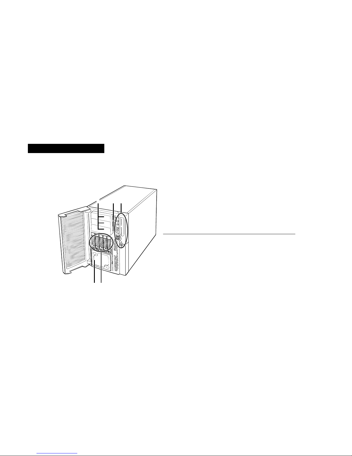
Table 1 and Figure 1 identify the features on the front of your pedestal/rack server chassis.
Figure 1. Pedestal/Rack Chassis Front Panel Component Layout
123
45
Tab le 1 :Pedestal/Rack Chassis Front Panel Components
1 Three 5.25-inch peripheral bays
2 3.5-inch diskette drive bay
3 Front control panel (for more information, refer to "Front Control
Panel View" on page 2-7)
4 Hot-swap drives
5 Hard drive backplane bay
Page 8
SYSTEM FEATURES
Pedestal/Rack Chassis
2-7
.....
Front Control Panel View
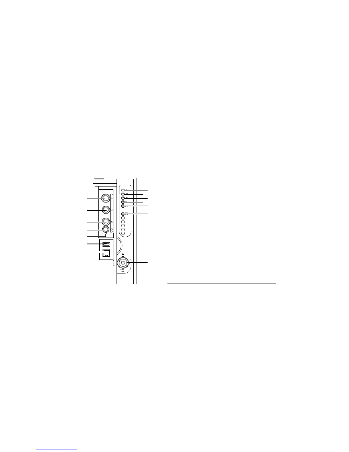
Table 2 and Figure 2 identify the buttons and LEDs on the front control panel of your
pedestal/rack server. (For descriptions of the front control panel features, refer to page 2-12.)
Figure 2. Pedestal/Rack Chassis Front Control Panel Component Layout
Tab le 2 :Pedestal/Rack Chassis Front Control Panel Components
1 Power bu tton
2 Sleep button
3 Reset button
4 Chassis ID button
5 NMI switch
6 USB port
7 Serial port
8 Main power LED
9 Faul t LED
10 Hard drive activity LED
11 LAN1 LED
12 LAN2 LED
13 Chassis ID LED
14 Lock
1
2
3
4
5
6
9
10
11
12
7
8
13
14
Page 9
SYSTEM FEATURES
Pedestal/Rack Chassis
2-8
2
Back Panel View
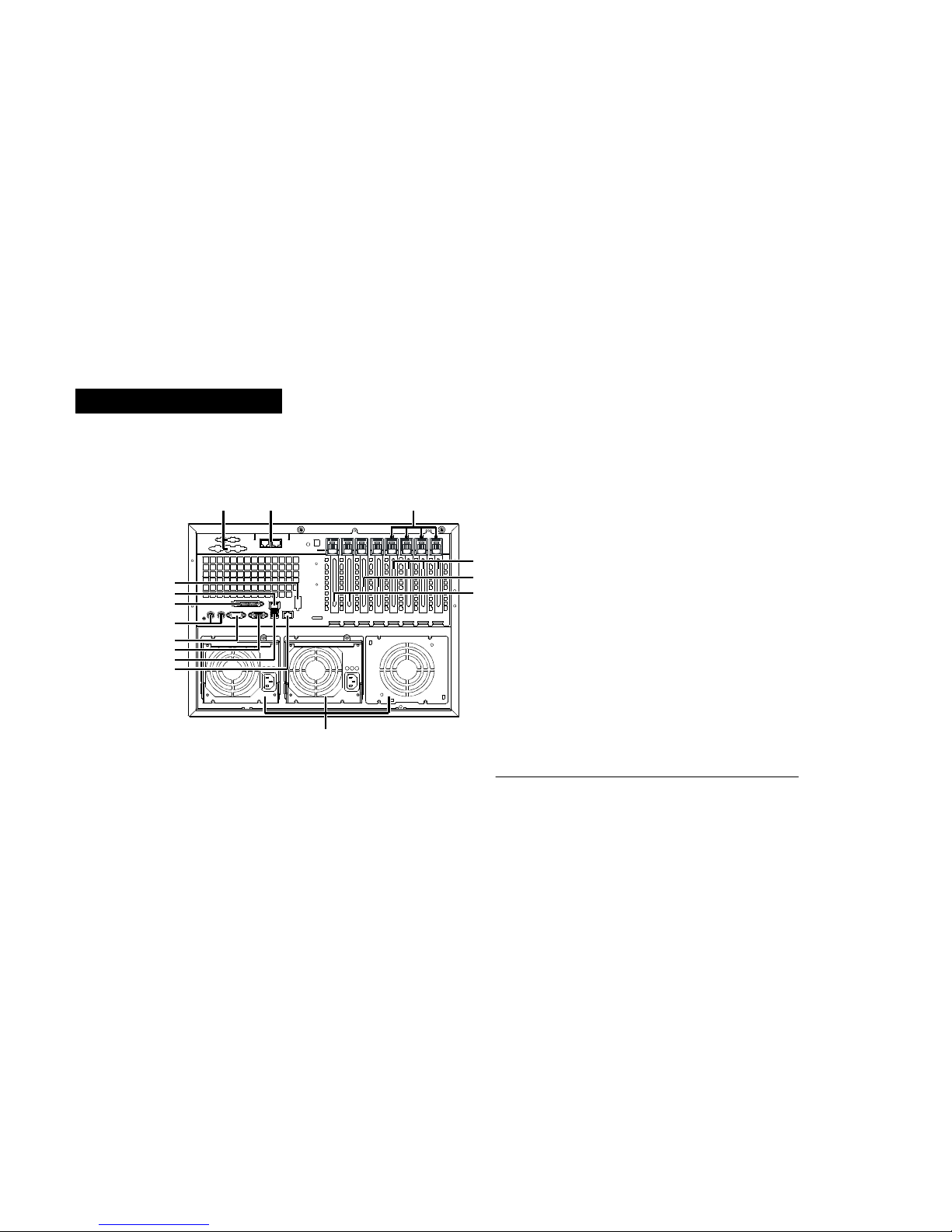
Table 3 and Figure 3 identify the connectors on the back panel of your pedestal/rack server.
Figure 3. Pedestal/Rack Chassis BackPanel Connector Layout
12 3
4
5
6
7
8
9
10
11
12
13
14
15
Tab le 3:Pedestal/Rack Chassis BackPanel Connectors
1 Optional VHDCI SCSI & SCSI connector knocko uts
2 Optional ICMB por ts 1 (left) & 2 (right)
3 Hot-pl ug PCI LEDs
4 Hot-plug 64-bit PCI-X add-in card slots
5 Non-hot-plug 64-bit, 100 MHz PCI-X add-in card slot
s
6 Non-hot-plug 32-bit, 33 MHz PCI add-in car d slots
7 Power supply bays
8 LAN2 Gbit RJ45 connector
9 USB ports 0 (upper) & 1 (lower)
10 Video connector
11 Serial port A
12 PS/2-compatible mouse & keyboard ports
13 IEEE 128 4 enhanced parallel port
14 LAN1 100/10 RJ45 connector
15 Knockout for optional serial port B
Page 10
SYSTEM FEATURES
Rack Optimized Chassis
2-9
.....
................................................................ ...
RACK OPTIMIZED CHASSIS
Front Panel View
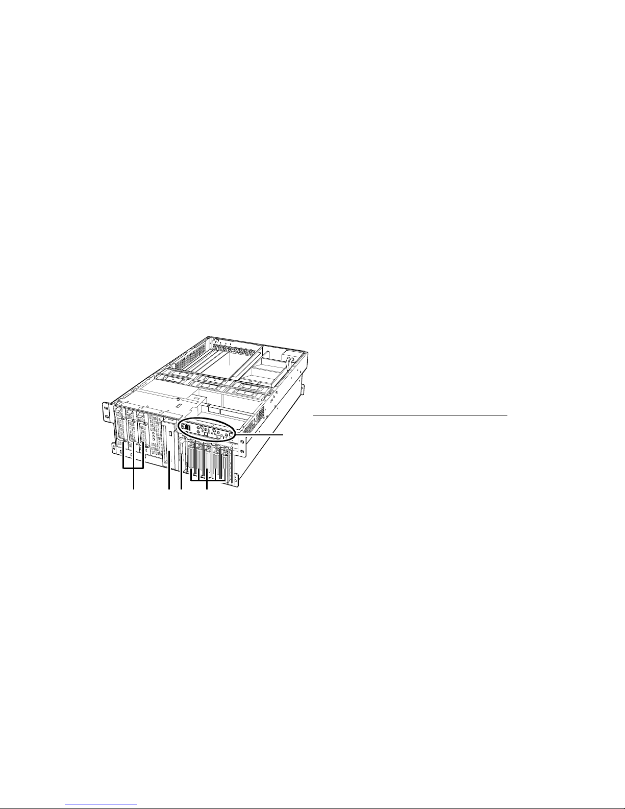
Table 4 and Figure 4 identify the features on the front panel of your rack optimized server.
Figure 4. RackOptimized Chassis Front Panel Component Layout
1234
5
Tab le 4 :RackOptimized Chassis Front Panel Components
1 Power supply bay
2 5.25-inch peripheral bay
3 Media bay with 3.5-inch diskette & CD-ROM drive
4 Hot-swap drives
5 Front Control Panel (for more information, refer to
"Front Control Panel View" on page 2-10)
Page 11
SYSTEM FEATURES
Rack Optimized Chassis
2-10
2
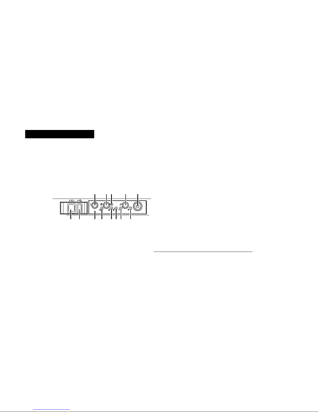
Front Control Panel View
Table 5 and Figure 5 identify the buttons and LEDs on the front control panel of your rack
optimized server. (For descriptions of the front control panelfeatures, refer to page 2-12.)
Figure 5. RackOptimized Chassis Front Co ntrol Panel Component Layout
123 45
678910111213
Tab le 5 :RackOptimized Chassis Front Control Panel Components
1 Sleep button
2 Chassis ID button
3 Chassis ID LED
4 Reset button
5 Power button
6 Main power LED
7 Hard drive activity LED
8 LAN2 LED
9 LAN1 LED
10 Fault LED
11 NMI switch
12 USB port
13 Serial port
Page 12
SYSTEM FEATURES
Rack Optimized Chassis
2-11
.....
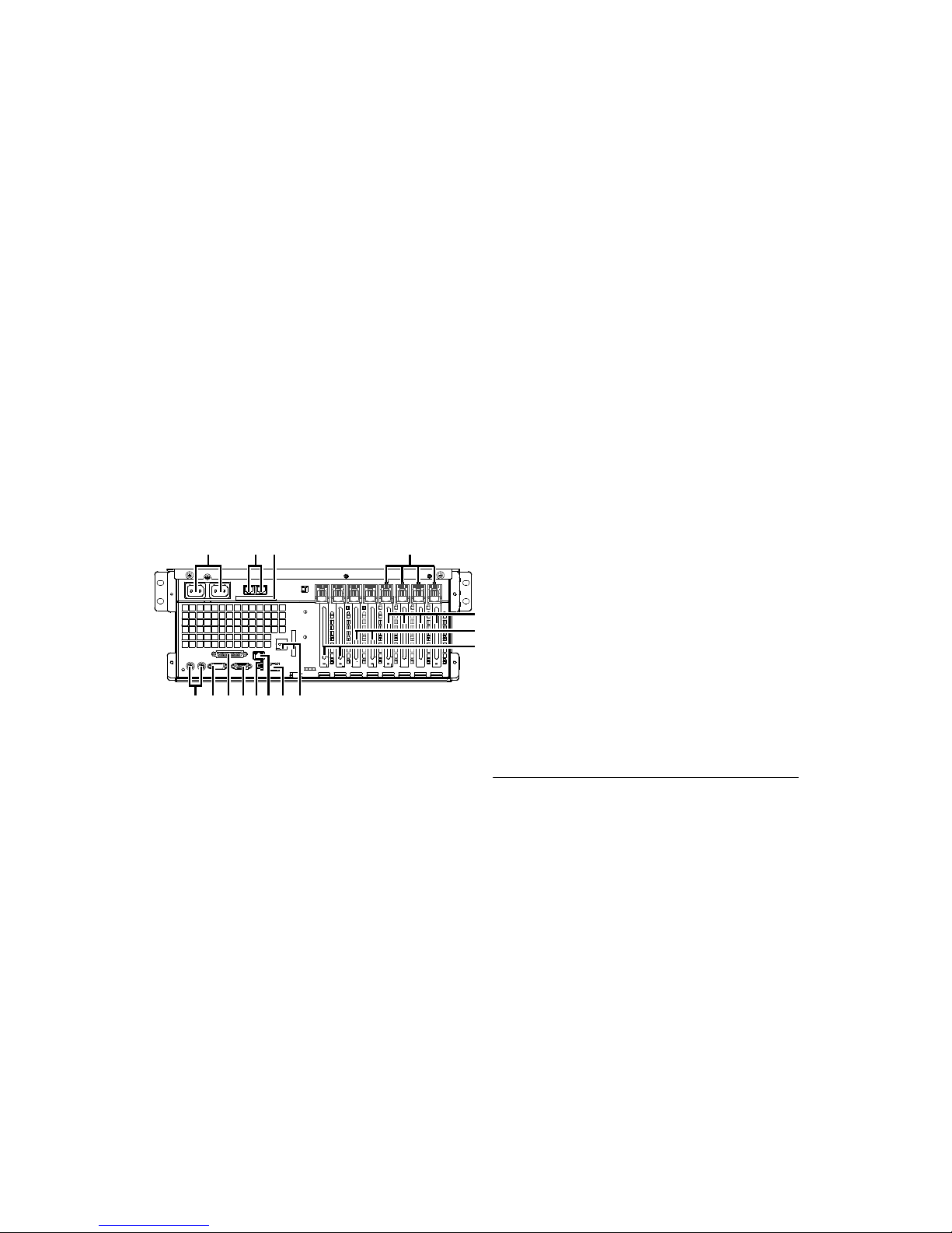
Back Panel View
Table 6 and Figure 6 identify the connectors on the back panel of your server.
Figure 6. RackOptimized Chassis BackPanel Connector Layout
123
4
5
6
7
89101112131415
Tab le 6: RackOptimized Chassis BackPanel Connectors
1 Power supply AC inlet 1 & 2
2 Optional ICMB por ts 1 ( left) & 2 (right)
3 Knockout for optional SCSI connector
4 Hot-plug PCI LEDs
5 Hot-plug 64-bit PCI-X add-in card slots
6 Non-hot-plug 64-bit, 100-MHz PCI-X add-in card slots
7 Non-hot-plug 32-bit, 33-MHz PCI add-in card slots
8 Optional VHDCI SCSI & serial B connector knockout
9 LAN2 Gbit port
10 LAN1 100/10 RJ45 connector
11 USB ports 0 (upper) & 1 (lower)
12 Video connector
13 IEEE 128 4 enhanced parallel port
14 Serial port A
15 PS/2-compatible mouse & keyboard ports
Page 13

SYSTEM FEATURES
Front Control Panel Descriptions
2-12
2
................................................................ ...
FRONT CONTROL PANEL DESCRIPTIONS
Table 7 describes the features located on your server’s front control panel.To view the layout of
the front control panel features, refer to "Front Control Panel View" on page page 2 -7 for the
pedestal/rack chassis, and refer to "Front Control Panel View" on page 2-10 for the rack
optimized chassis.
Tab le 7:Front Control Panel Feature Description
............
Feature
......................................
.
Description
Power button To turn the power on, briefly press the power button. Note that if the system is in a sleep state,
briefly pressing the power button brings the system out of the sleep state.
To turn the power off, press and hold the power button for more than four seconds. This overrides
ACPI mode.
Main power LED A solid green light indicates the presence of DC power in the server. A flashing green light
indicates that the system is i n ACPI sleep mode.
Sleep button To put a system suppo rting ACPI into sleep mode (S1), brie fly press the sleep bu tton.
To wake a system from sleep mode, briefly press the sleep button.
Reset button To reset the system, briefly press the reset button.
To clear the CMOS, complete the following steps:
1. Press and hold the reset button for at least four seconds.
2. While pressing and holding the reset button, press and hold the power button.
3. At the same time, release both the reset and power buttons. The system will power on, and
theCMOSwillbereset.
Page 14

SYSTEM FEATURES
Front Control Panel Descriptions
2-13
.....
NMI switch Using this switch causes a non-maskable interrupt. The NMI switch is located behind the bezel
door.
USB port USB port 3 is located behind the bezel door.
Serial port Serial port B is located behind the bezel door.
Fault LED A red light indicates any system fault condition.
Hard drive activity LED A green light indicates system hard drive activity.
LAN1 LED A green light indicates LAN1 activity.
LAN2 LED A green light indicates LAN2 activity.
Chassis ID button Pressing this button illuminates LEDs on both the front and rear of the chassis, which simplifies
identif ication of t he chassis in a rack from the rear.
Chassis ID LED A blue light indicates the chassis ID is active.
Tab le 7:Front Control Panel Feature Description (Continued)
............
Feature
......................................
.
Description
Page 15

SYSTEM FEATURES
Front Control Panel Descriptions
2-14
2
Page 16

3-15
.....
...................................
S
YSTEMBOARDFEATURES
3
The following chapter provides information about your server’s system board, memory,
processors, and jumpers.
Note
..........................................
..........................................
The appearance, location, and exist ence o f the components mentioned may v ary by model.
Page 17
SYSTEM BOARD FEATURES
System Board Components
3-16
3
................................................................ ...
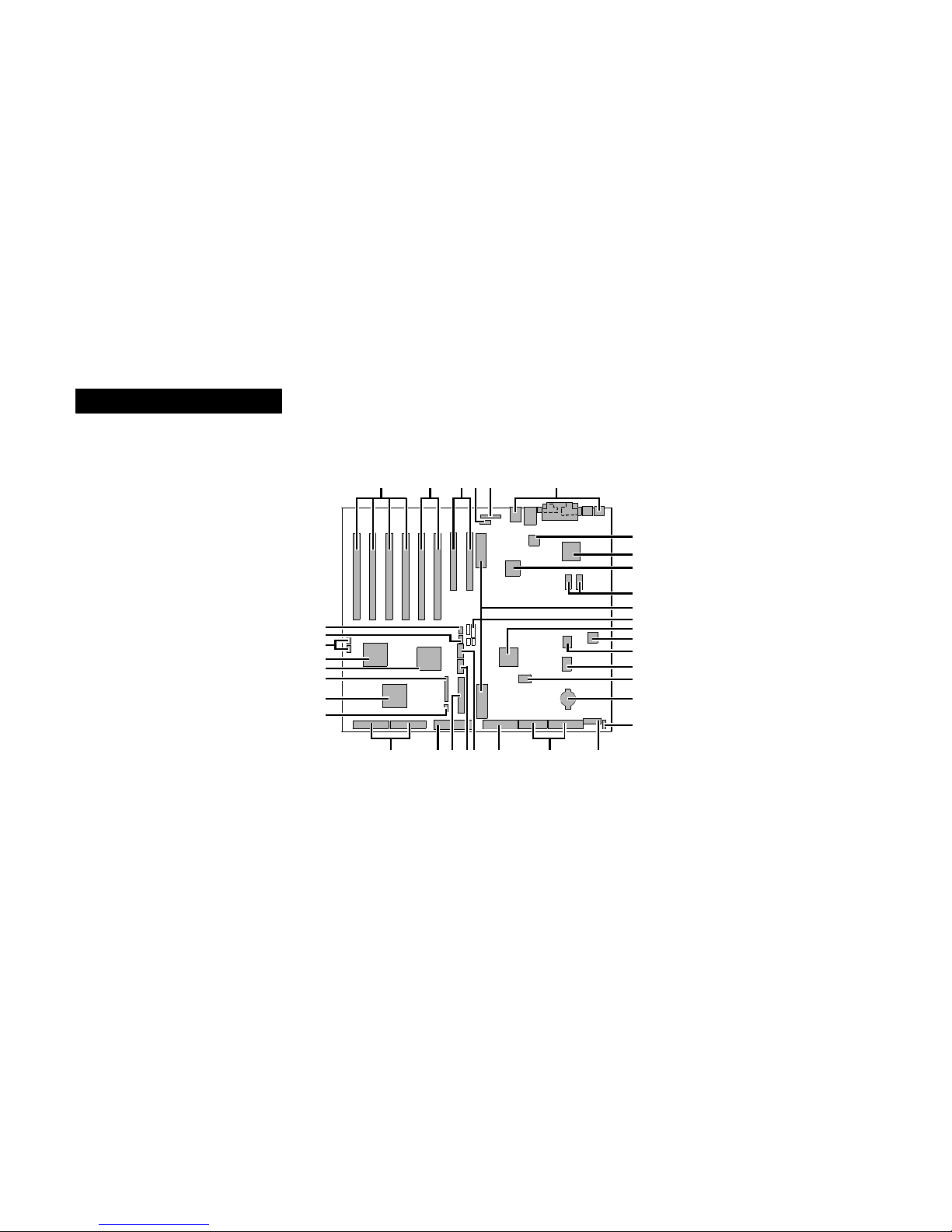
SYSTEM BOARD COMPONENTS
Use Figure 7 below and Table 8 on page 3-17 to identify the components on your system board.
Figure 7.SystemBoardLayout
ABCDE F
G
H
I
J
K
L
M
N
O
P
Q
R
S
TUVWXYZAA
BB
CC
DD
EE
FF
GG
HH
II
Page 18

SYSTEM BOARD FEATURES
System Board Components
3-17
.....
Tab le 8:System Board Components
...
Letter
....................
.
Component Description
...
Letter
....................
.
Component Description
A 64-bit Hot-Plug PCI-X Slots O BIOS Flash Component
B 64-bit, 100-MHz, Non-Hot-Plug PCI-X S lots P PC87417 Super I/O Controller
C 32-bit, 33-MHz, Non-Hot-Plug PCI Slots Q BMC Flash Component
D Intelligent Chassis Management Bus (ICMB)
Connector (P24)
R Battery
E Hot-Plug Indicator Board (HPIB) Connector (P23) S Chassis Intrusion Detect Connector (P36)
F Back Panel I/O Connectors T 14-pin Power Control Connector (P35)
G Intel 82550 Ethernet Controller U 24-pin Power Connector (P32)
H ATI Rage XL 2D/3D Graphics Accelerator V 20-pin Power Connector (P28)
I Intel 82544 Ethernet Controller W Serial Port B Connector (P17)
J Video RAM (VRAM) (4 MB total) X USB #3 Header (P18)
K Processor Board Connectors (P21 and P22) Y Front Panel Header (P19)
L Jumper Block JP4 Z IDE Connector (P13)
M ServerWorks South Bridge Controll er (CSB5) AA S CSI LVD Connec tors (P4 and P7)
N BMC Component BB Intelligent Platfor m Management Bu s (IPMB)
Connector (P12)
Page 19

SYSTEM BOARD FEATURES
System Board Components
3-18
3
CC Adaptec 7899 SCSI Controller GG RAID LED Connectors (P1 and P2)
DD Fan Connector (P11) HH Hot-Swap Backplane (HSBP) Connector (P16)
EE ServerWorks PCI Bus Bridge Controller (CIOB30) II HSBP Connector (P15)
FF ServerWorks PCI Bus Bridge Controller (CIOB30)
Tab le 8:System Board Components (Continued)
...
Letter
....................
.
Component Description
...
Letter
....................
.
Component Description
Page 20

SYSTEM BOARD FEATURES
Memory Specifications
3-19
.....
................................................................ ...
MEMORY SPECIFICATIONS
The system board contains twelve dual in-line memory module (DIMM) slots that support PC200-compliant registered ECC DDR DRAM DIMMs.
•
Minimum configuration: Four 128-MB DIMMs for a total of 512 MB.
•
Maximum configuration: Twelve 2-GB stacked DIMMs for a total of 24 GB.
The controller automatically detects, sizes, and initializes the memory array, depending on the
type, size, and speed of the installed DIMMs, and reports memory size and allocation to the
server via configuration registers.
Caution
...........................................
Use extreme care when installing a DIMM. Applying too much pressure can damage the socket.
...........................................
Keyed DIMMs insert only one way.
Note
...........................................
...........................................
Always fil l banks completely. The system ignores partially filled banks.
Page 21
SYSTEM BOARD FEATURES
Memory Specifications
3-20
3
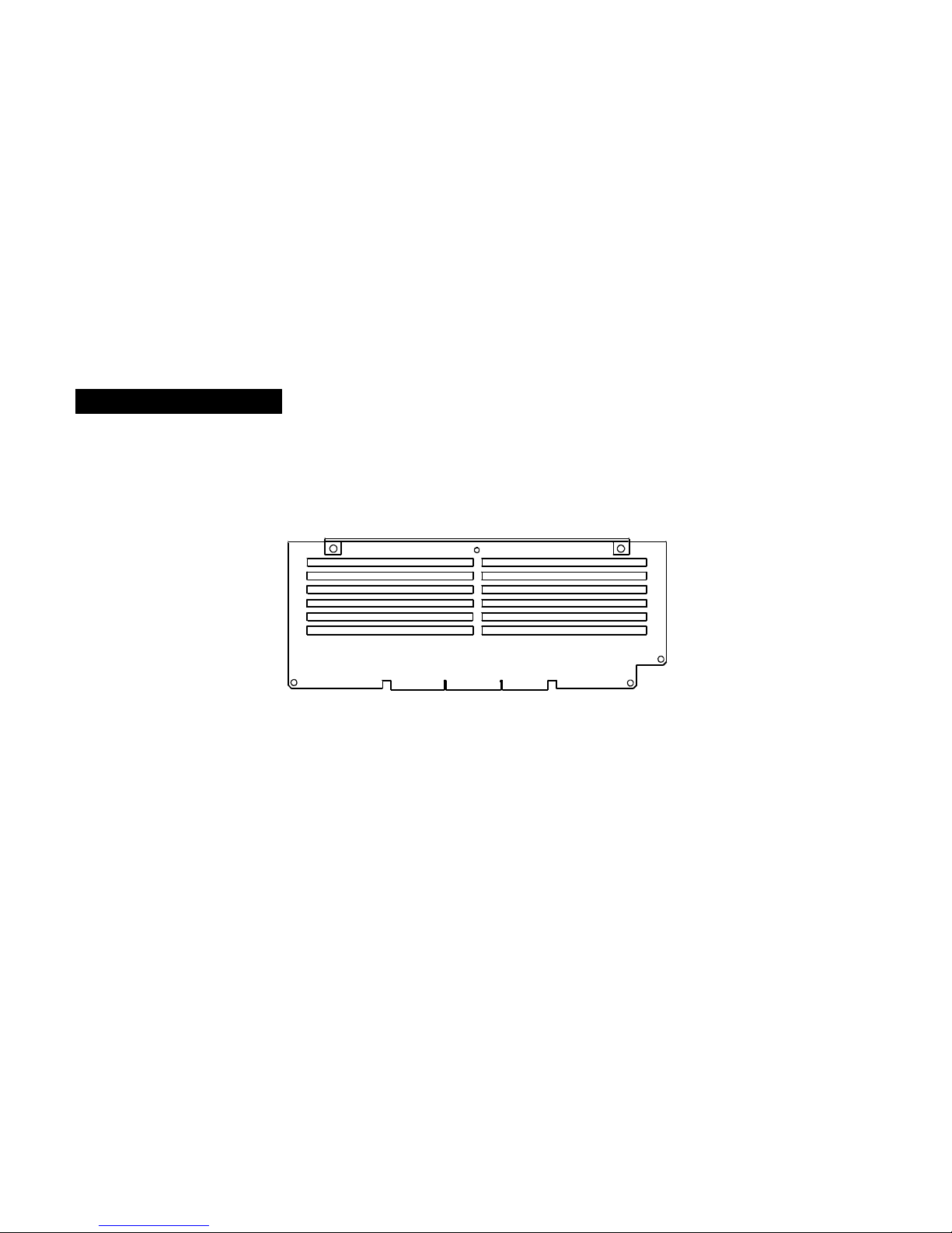
Memory Bank Order
Load the DIMMs in the following order:
1 Bank 1: DIMMs # 1, 2, 3, and 4
2 Bank 2: DIMMs # 5, 6, 7, and 8
3 Bank 3: DIMMs # 9, 10, 11, and 12
Figure 8.MemoryBanks
1
3
5
7
9
11
2
4
6
8
10
12
Page 22
SYSTEM BOARD FEATURES
Processor Specifications
3-21
.....
................................................................ ...
PROCESSOR SPECIFICATIONS
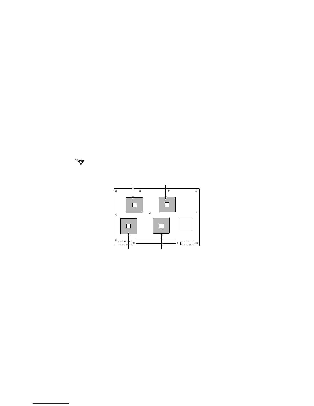
The NetFRAME 6500 accommodates one to four Intel® Xeon processors.
Note
...........................................
You must install a processor in processor socket 1. When installing multiple processors, populate the
...........................................
processor sockets in the order shown below.
Figure 9. Correct Order for PopulatingProcessor Sockets
12
3
4
Page 23
SYSTEM BOARD FEATURES
System Board Jumpers
3-22
3
................................................................ ...
SYSTEM BOARD JUMPERS
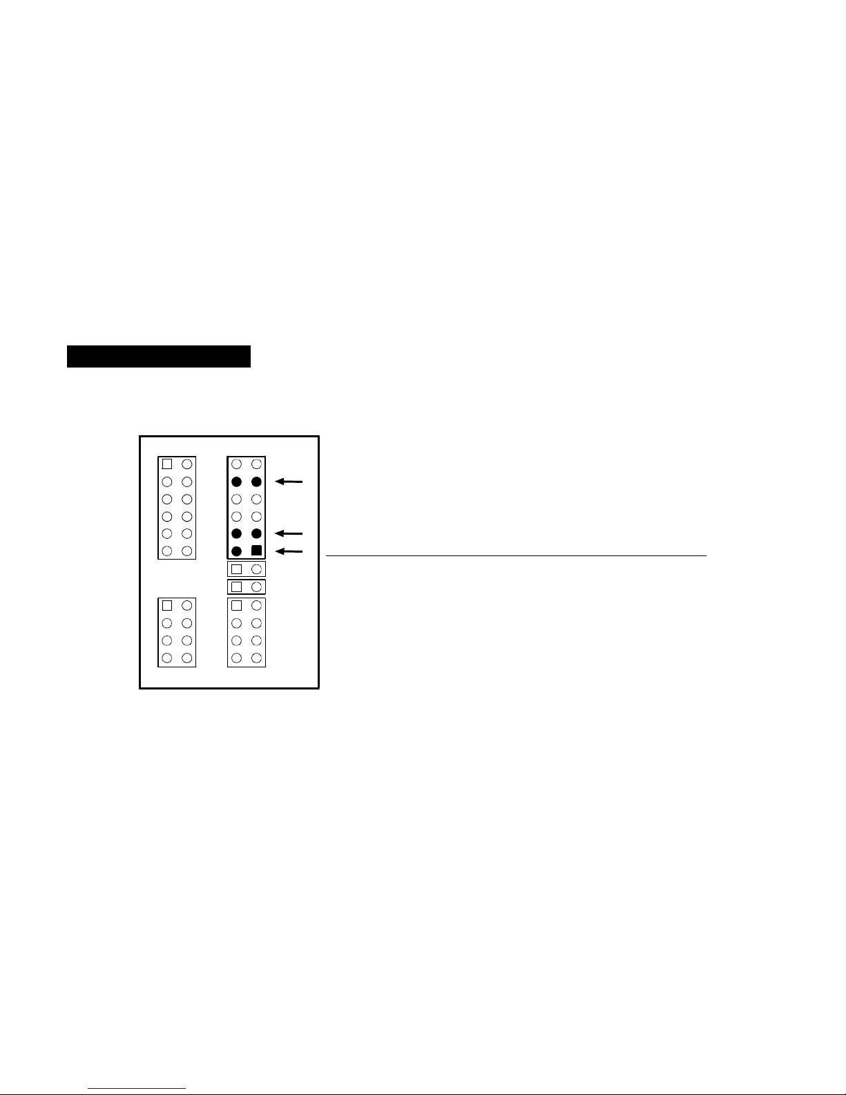
Jumper block JP4 includes pins for several BIOS reset operations.Table 9 and Figure 10 identify
these pins. For normal operation, jumpers should not be installed on any of the identified pins.
Figure 10. Jumper BlockLayout
21
12 11
JP4
12
78
JP8
12
11 12
JP3
12
78
JP7
A
B
C
Tab le 9:Jumper BlockJP4 Description
..
Pins
.......
.
Jumper Name
....................
Description
A CMOS Clear If pins 1 and 2 are jumpered, the CMOS settings
are cleared.
B Password Clear If pins 3 and 4 are jumpered, the user and
administrator passwords are cleared.
C Recovery Boot If pins 9 and 10 are jumpered, the system will
attempt to recover the BIOS.
Page 24

 Loading...