

Page 1

MicronPC Millennia
®
XP+
User’s Guide
Odyssey, MAS001662-00, MAL, 11-7-2001
Page 2

USER’S GUIDE
Copyright Notice
ii
...................................................................
COPYRIGHT NOTICE
Copyright 2001 MicronPC, LLC. All rights reserved. The information in this document is subject to change
without prior notice in order to improve reliability, design, and function and does not represent a commitment
on the part of the manufacturer. In no event will the manufacturer or seller of a MicronPC product be liable
for direct, indirect, special, incidental, or consequential damages arising out of the use or inability to use the
product or documentation, even if advised of the possibility of such damages. Except as stated in the
applicable MicronPC, LLC limited warranty, MicronPC and its affiliates, by this manual, make no other
express warranties and all other warranties, including, without limitation: THE IMPLIED WARRANTY OF
MERCHANTABILITY AND THE IMPLIED WARRANTY OF FITNESS FOR A PARTICULAR PURPOSE
ARE HEREBY DISCLAIMED.
This document contains proprietary information that is protected by copyright. No part of this document may
be photocopied, reproduced, or translated to another language without the prior written consent of:
MicronPC, LLC
906 E. Karcher Road, Nampa, Idaho 83687
Trademark Notice
Windows, MS-DOS, and Microsoft are registered trademarks of Microsoft Corporation. AMD, the AMD logo,
and combinations thereof are trademarks of Advanced Micro Devices, Inc. Other product names mentioned
herein are used for identification purposes only and may be trademarks and/or registered trademarks of
their respective companies.
Limitation of Liability
While reasonable efforts have been made to ensure the accuracy of this manual, the manufacturer and
seller assume no liability resulting from errors or omissions in this manual or from the use of the information
contained herein.
Page 3

TABLE OF CONTENTS
iii
.....
...........................................
Table of Contents
Copyright Notice....................................................................... ii
Trademark Notice ............................................................. ii
Limitation of Liability.......................................................... ii
Welcome........................................................ 7
MicronPC Resources............................................................... 8
Easy Setup Guide............................................................. 8
Service and Support Solutions.......................................... 8
Further Reading................................................................ 8
For More Information ........................................................ 8
Manual Comments............................................................ 8
System Information.................................................................. 9
Manual Conventions .............................................................. 10
Special Text .................................................................... 10
Safety Information ...................................... 11
Electrostatic Discharge (ESD)................................................ 14
System Care................................................ 15
Operating Environment .......................................................... 15
Temperature Concerns................................................... 15
Moisture and Humidity Concerns.................................... 16
Other Environmental Concerns...................................... 16
Noise Concerns.............................................................. 17
Transporting .......................................................................... 17
Cleaning ................................................................................ 18
Protecting .............................................................................. 18
System Features ......................................... 19
Front Panel Components ...................................................... 20
Rear Panel Connectors......................................................... 21
Connector Icons............................................................. 22
Setting Up Your Computer......................... 23
Connecting the Components................................................. 23
Connecting Power to Your System........................................ 28
Turning On Your System............................ 29
Running Your System for the First Time................................ 29
Internet Access .............................................................. 31
Standby Mode................................................................ 32
Light Emitting Diodes (LEDs) ......................................... 35
Turning Off Your System ....................................................... 36
Manual Shutdown .......................................................... 37
Page 4

TABLE OF CONTENTS
iv
System Reset ................................................................. 37
Restarting Your System ......................................................... 38
Backing Up Your System ....................................................... 38
Ergonomic Tips ...................................................................... 39
Setting Up Your Workstation........................................... 39
Sitting At Your Workstation ............................................. 39
Maintaining a Comfortable Workstation.......................... 40
Reducing Eye Strain....................................................... 40
Performing Exercises...................................................... 40
Using Your Computer................................. 41
Internet Overview................................................................... 41
Internet Service Provider ................................................ 42
Using a Web Browser ..................................................... 42
Surfing Tips..................................................................... 42
E-mail Overview..................................................................... 43
Keyboard Overview................................................................ 44
Installing Software...................................... 47
Installing Additional Software................................................. 47
Installing Software Automatically .................................... 48
Installing Software from a CD or Floppy Disk................. 48
Reinstalling Factory Software ................................................ 49
Operating System Recovery CD..................................... 49
Image Restore CD .......................................................... 50
Taking Apart Your System......................... 51
Tools and Preparation ........................................................... 52
Electrostatic Discharge (ESD) Cautions ........................ 52
Removing and Replacing the Access Panel ......................... 53
Removing the Access Panel .......................................... 53
Replacing the Access Panel .......................................... 54
Removing and Replacing the Bezel ...................................... 55
Removing the Bezel....................................................... 55
Replacing the Bezel ....................................................... 56
Removing and Replacing the Bezel Door ............................. 57
Removing the Bezel Door .............................................. 57
Replacing the Bezel Door .............................................. 58
Installing and Removing Hardware ........... 59
Removing and Installing a PCI or AGP Card ........................ 61
Removing a PCI or AGP Card ....................................... 61
Installing a PCI or AGP Card ......................................... 64
Removing and Installing Drives............................................. 65
Removing a 3.5-inch or 5.25-inch Drive ......................... 65
Installing a 3.5-inch or 5.25-inch Drive........................... 67
Removing a Hard or Floppy Disk Drive.......................... 69
Installing a Hard or Floppy Disk Drive ............................ 70
Installing and Removing Memory .......................................... 71
Installing DIMM Modules................................................ 72
Removing DIMM Modules.............................................. 74
Page 5

TABLE OF CONTENTS
v
.....
Removing and Installing the Power Supply............................ 75
System Board.............................................. 77
Features................................................................................. 77
Processor Information..................................................... 77
Main Memory .................................................................. 78
Expansion Slots.............................................................. 78
On-Board Peripherals..................................................... 78
On-Board Sound............................................................. 78
System Board Features ......................................................... 79
Input/Output Connector Ports ......................................... 80
CMOS Real Time Clock (RTC) .............................................. 81
Flash EEPROM............................................................... 81
Removing and Installing the System Board ........................... 81
Removing the System Board .......................................... 81
Installing the System Board ............................................ 84
BIOS Setup Program .................................. 85
Running the Setup Program................................................... 86
Changing the BIOS Settings .................................................. 87
CMOS Setup Utility Menu...................................................... 88
Standard CMOS Features Menu............................................ 90
Advanced BIOS Features Menu ............................................ 92
Advanced Chipset Features Menu......................................... 94
Integrated Peripherals Menu.................................................. 96
MCP OnChip IDE Device Submenu...................................... 98
MCP OnChip PCI Device Submenu.................................... 100
Onboard Super IO Device Submenu................................... 102
Power Management Setup Menu........................................ 104
IRQ/Event Activity Detect Submenu.................................... 106
IRQs Activity Monitoring Submenu...................................... 108
PnP/PCI Configuration Menu ............................................... 110
PC Health Status Menu........................................................ 112
Troubleshooting Appendix ...................... 115
For More Information............................................................ 116
Cautions ............................................................................... 116
Power Issues and Solutions................................................. 117
Sound Issues and Solutions................................................. 118
Monitor Issues and Solutions .............................................. 120
Modem Issues and Solutions .............................................. 122
Boot Error Issues and Solutions.......................................... 124
CD-ROM and Floppy Disk Drive Issues and Solutions ....... 126
Service and Support Appendix................ 129
MicronPC Online Support Tools .......................................... 129
MServices .................................................................... 130
MicronPC U.................................................................. 130
MicronPC Technical Support............................................... 130
Before You Call............................................................ 130
Page 6

TABLE OF CONTENTS
vi
Contacting Technical Support....................................... 131
Service Chart ................................................................ 132
Regulatory Appendix................................ 133
FCC Notices......................................................................... 134
FCC Class A Digital Device Notice .............................. 134
FCC Class B Digital Device Notice .............................. 135
Compliance Information Statement ..................................... 136
Glossary..................................................... 137
Page 7

1-7
.....
...................................
W
ELCOME
1
Thank you for buying a MicronPC computer. This
User’s Guide
provides setup instructions to
help you quickly get started using your new computer. The
User’s Guide
also provides detailed
information and instructions on the following:
•
safety
•
system care
•
taking your system apart
•
replacing and installing hardware
•
system board features
•
BIOS (CMOS) setup
•
troubleshooting
Page 8

WELCO ME
MicronPC Resources
1-8
1
...................................................................
MICRONPC RESOURCES
MicronPC provides several resources to assist you with using your new computer.
Easy Setup Guide
For quick step-by-step system setup instructions, refer to the
Easy Setup Guide
.
Service and Support Solutions
The “Service and Support Appendix” chapter on page B-129 provides contact information and an
overview of MicronPC services that are designed to make your computing experience more
enjoyable.
Further Reading
It is recommended that you read all documentation, in addition to this manual, related to any
software or hardware supplied with your computer (such as your monitor, speakers, and
keyboard).
For More Information
For the latest information about your computer and MicronPC services, please visit the MicronPC
Web site at www.micronpc.com.
Manual Comments
If you would like to comment on these manuals or if you have any suggestions to make them
better, please contact us at [email protected].
Page 9

WELCO ME
System Information
1-9
.....
...................................................................
SYSTEM INFORMATION
Please record your computer’s Serial Number; it is located on the FCC label on the back panel of
your computer. If you should require technical support in the future, the information you record
below will help a MicronPC support technician locate the specifications for your system and aid in
returning it to normal operation. For service and support contact information, please see the
“Service and Support Appendix” on page B -129.
Tab le 1: System Information
..........................................
Model and Serial Number Information
Purchase Date
Serial Number
Model Name
MS6373-ODY Tool Free Mini Tower
Manual Number
MAS001662-00
Page 10

WELCO ME
Manual Conventions
1-10
1
...................................................................
MANUAL CONVENTIONS
The following conventions are used throughout this manual.
Note
...........................................
...........................................
Important information concerning the operation of your computer.
Caution
...........................................
Failure to follow directions could result in loss of data or damage to equipment. Failure to heed these cautions
...........................................
could negate the user warranty.
Warning
...........................................
Failure to follow directions will result in loss of data or damage to equipment, and/or could result in physical
...........................................
harm. Failure to heed these warnings could negate the user warranty.
Special Text
The text in this guide is formatted to highlight unique information or instructions. Review the following examples of special text used throughout this
manual:
•
Screen (window) names, functions, or anything that appears on the screen is formatted in bold. For example: Click OK,theStandards
screen, the Edit menu.
•
Keyboard strokes are indicated by brackets. For example: Press [Enter], use the [Alt] key. When keys should be held down simultaneously,
they are separated by the + sign. For example: Press [Ctrl+Alt+Delete]. When keys should be pressed sequentially, they will be in
individual brackets without the plus sign. For example: Press [1][Enter]. The [1] key should be pressed first and then the [Enter] key should
be pressed.
•
Screen messages are indicated by quotes. For example: The message “Enter your username and password” will appear.
•
Anything that you need to type will appear in italics. For example: Enter the word
password.
Page 11

2-11
.....
...................................
S
AFETYINFORMATION
2
The following instructions pertain to the risk of fire, electric shock, or bodily injury. Please read
all of these instructions carefully and save them for later use.
•
Follow all the instructions and warnings marked on this product or included in this
manual.
•
Do not use this product on an unstable surface. The product might fall, causing serious
damage to the product.
•
Slots and openings in the computer are provided for ventilation. To ensure the reliable
operation of your product, and to protect it from overheating, these openings must not be
blocked or covered. Do not use this product on a bed, sofa, rug, or other soft surface.
This product must never be placed near or over a radiator or heat register. This product
must not be placed in a built-in enclosure of any kind unless proper ventilation is
provided.
Page 12

SAFETY INFORMATION
2-12
2
•
Never push objects of any kind into the product through the cabinet openings. They may
touch dangerous voltage points or short out parts — possibly resulting in an electric shock
or a fire hazard.
•
Never spill liquid of any kind on the product.
•
This product must only be connected to the AC power source as indicated on the power
supply information label. If you are not sure of the type of AC power available, ask the local
power company. Only connect this product to a power outlet that matches the power
requirements of this product.
•
Do not allow anything to rest on the power cord. Do not place this product where people
might walk on the cord.
•
If you use an extension cord with this product, make sure that the total amperage rating of
all equipment plugged into it does not exceed the amperage rating of the extension cord.
Ensure that all the products plugged into the main AC power outlet do not exceed 15 amps.
•
Unplug the product from the main electrical AC power outlet before cleaning. Do not use
liquid or aerosol cleaning solvents directly on the product. Use a damp cloth for cleaning the
exterior surfaces.
•
Do not use this product near standing bodies of water or humid environments.
Page 13

SAFETY INFORMATION
2-13
.....
•
Unplug this product from the main AC power outlet and call for service if any of the following
conditions occur:
•
The power cord or plug is damaged or frayed.
•
Liquid has been spilled into the product.
•
The product has been exposed to rain or corrosive liquids.
•
The product has been dropped, or the case has been damaged.
•
The product’s performance changes, indicating a need for service.
Warning
...........................................
Do NOT open the power supply cover; hazardous voltages are present. There are no user-
...........................................
serviceable components inside.
Warning
...........................................
There is a danger of explosion if the battery is incorrectly replaced. Replace the battery with one
recommended by the equipment manufacturer. Discard used batteries according to the
...........................................
manufacturer’s instructions.
Page 14

SAFETY INFORMATION
Electrostatic Discharge (ESD)
2-14
2
...................................................................
ELECTROSTATIC DISCHARGE (ESD)
Before working inside your computer, it is important to know how to protect your computer from
ESD damage.
Caution
...........................................
Modules1are Electrostatic Sensitive. A small electrostatic discharge (ESD) can damage computer
components. An ESD damaged module or PCI card might not fail immediately, but over time it could
become worse, possibly causing an intermittent problem. Be very careful to handle the module or
PCI card ONLY by the edges. DO NOT touch the gold/silver edge-connectors or any of the
components on the system board. Leave the module or PCI card in the antistatic bag until you are
...........................................
ready to install it.
1. modules: An independent assembly of electronic components with some distinct function. Example: A RAM module consisting of several
RAM chips mounted on a small circuit board.
Page 15

3-15
.....
...................................
S
YSTEM
C
ARE
3
Your MicronPC computer has been manufactured to the highest quality standards. With proper
care, it should provide years of trouble-free service. This section provides a few steps you can
take to ensure your system has the longest life possible.
.................................................................
OPERATING ENVIRONMENT
Temperature Concerns
The computer specifications ensure the computer will operate in ambient (room) temperatures
up to 95° F (35° C). It is very important to keep your system out of direct sunlight or other heat
sources (lamps, heating vents, etc.). Your computer is also equipped with ventilation fans.
Make sure the front and rear cooling-fan openings are not obstructed.
If room temperature consistently exceeds 95° F, move the system to a cooler location to keep
it under the maximum temperature.
Page 16

SYSTEM CARE
Operating Environment
3-16
3
Moisture and Humidity Concerns
While your computer will generally run better in cooler environments, there are components of
the computer that are adversely affected by cold temperatures. Also, exposing the computer to
cold temperatures can produce condensation that can damage individual components or destroy
your system and monitor.
Warning
...........................................
Never expose the computer to moisture; this could lead to an electrical shock or a fire hazard.
...........................................
Operating the computer in areas with high humidity can damage system components.
Other Environmental Concerns
High levels of dust, dirt, or smoke can damage your system. Place the system in an area with
good ventilation. Periodically check the computer case, front and rear, to ensure that dust or dirt
is not accumulating around any openings.
Tab le 2: Temperature and Humidity Operational Levels
................
Operational
...............
Non-Operational
Temp erature
41° F to 95° F (5° C to 35° C) 32° F to 122° F (0° C to 50° C)
Humidity
10 to 90% RH Non-condensing 5 to 95% RH Non-condensing
Page 17

SYSTEM CARE
Transporting
3-17
.....
Noise Concerns
Some computer components, such as fans and drives, when in operation, make noise. MicronPC
designs systems to make the least amount of noise possible. If your computer seems to make
excessive noise, open the case and see if there are any parts rubbing together or see where the
source of the noise is coming from. Fans tapping on wires, cables, or screws that are not
sufficiently tightened down sometimes produce excessive noise. If you are still experiencing
trouble with noise from your computer, call MicronPC Technical Support.
...................................................................
TRANSPORTING
Always turn off the computer before moving it. Any sudden jar or shock may permanently
damage the hard disk. Hard disks are more resistant to shock if they are shut down before they
are moved. If you are transporting the system over longer distances, completely repackage it in
its original packing material. If the original packaging is unavailable, pack with as much padding
as possible to ensure that the components are not exposed to excessive vibration or shock.
Tab le 3: Operational Shock, Vibration, and Altitude Levels
................
Operational
...............
Non-Operational
Shock
2 G, 11 ms, half-sine 50 G, 11 ms, half-sine
Vibration
2 grms, 20 to 500 Hz 3.1 grms, 5 to 500 Hz
Altitude
up to 10,000 ft up to 40,000 ft
Page 18

SYSTEM CARE
Cleaning
3-18
3
...................................................................
CLEANING
If the case becomes dirty through constant use or handling, use only a damp, dust-free cloth for
cleaning. Do not use abrasives or solvents as these may mar or scratch the case. Use window
cleaner (alcohol/ammonia free) and a damp, dust-free cloth to clean the monitor; however, make
sure the monitor has been turned off first. Never apply the window cleaner directly to the monitor
screen. Always spray the cloth first; then wipe down the screen. Cleaning kits designed to clean
floppy disk drives, DVD drives, and CD-ROM drives are available at most computer stores and
should be used periodically.
...................................................................
PROTECTING
To prevent normal electrical problems such as spikes or surges, install a power surge protector
between the wall outlet and all of the system’s connected components. If even one component is
not connected to the surge protector, the entire system could be at risk. You should note that
some power strips are not surge protectors but simply extension cords.
If your local area is subject to frequent electric power failures, MicronPC recommends attaching
an Uninterruptible Power Supply (UPS) to the computer and monitor. A UPS will provide time to
save all data files and properly turn off the system.
Caution
...........................................
If a storm enters your area, completely unplug the entire system from all electrical sources,
including telephone lines. Electricity from lightning can travel in on any line and destroy all
...........................................
connected components.
Page 19

4-19
.....
...................................
S
YSTEMFEATURES
4
The following sections in this chapter will help you locate and identify the components and
connectors on your computer’s front and rear panels.
Note
..........................................
..........................................
The appearance, location, and existence of the items mentioned may vary by model.
Page 20
SYSTEM FEATURES
Front Panel Components
4-20
4
...................................................................
FRONT PANEL COMPONENTS
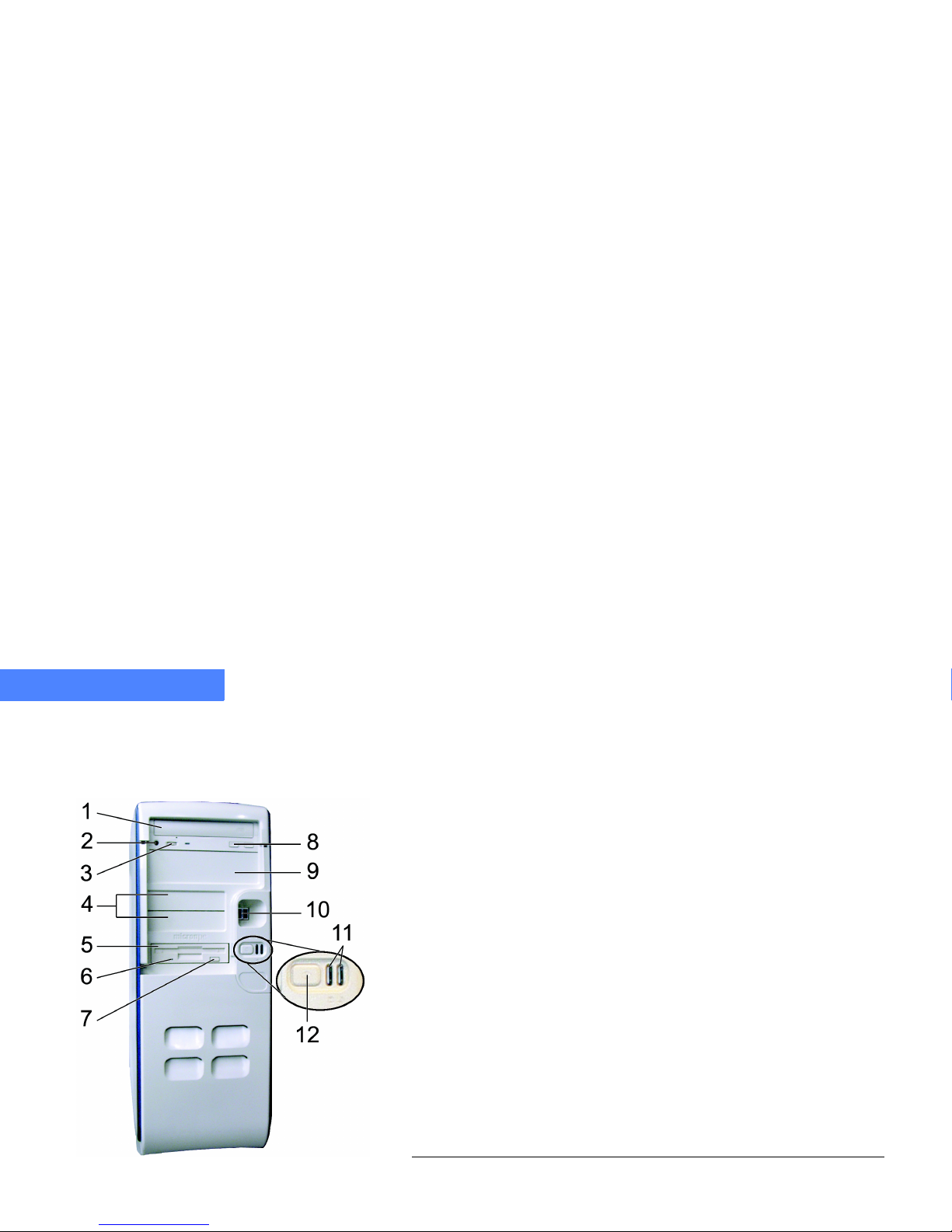
Figure 1 identifies the components on the front panel of your Tool Free Mini Tower.
Figure 1. Front Panel Component Layout
Tabl e 4: Tool Free Mini Tower Front Panel Components
1 CD, DVD, or CD-RW Disk Drive
2 CD, DVD, or CD-RW Disk Drive Headphone Jack (Windows
®
Me is not configured to work with the headphone jack)
3 CD, DVD, or CD-RW Headphone Jack Volume Control
4 Two 3.5-inch expansion bays
5 Floppy Disk Drive or LS-120
6 Floppy Disk Drive LED — the LED indicates that the floppy disk
is being accessed
7 Floppy Disk Drive Eject Button
8 CD, DVD, or CD-RW Disk Drive Eject Button
9 One 5.25-inch expansion bay (e.g. CD, DVD, CD-RW)
10 USB Ports
11 Power Status LEDs — the green LED indicates normal operation
and the red LED indicates the system is in standby mode
12 Multi-function Power Button
Page 21
SYSTEM FEATURES
Rear Panel Connectors
4-21
.....
...................................................................
REAR PANEL CONNECTORS
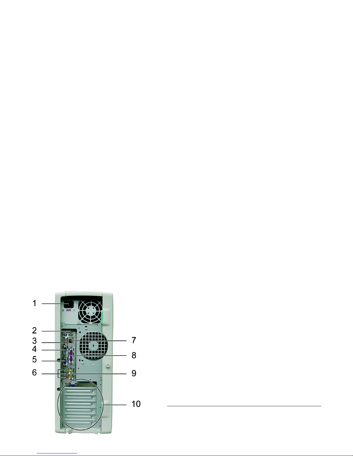
Figure 2 identifies the connectors on the rear panel of your system.
Figure 2. Rear Panel Connector Layout
Tab le 5: Rear Panel Connectors
1 AC Power Supply
2 PS/2 Mouse (green) and Keyboard (purple)
3 Two stacked USB ports (black)
4 Serial (Com 1) port (teal)
5 Video port (blue)
6 Audio out (lime)
Audio in (light blue)
Microphone (pink)
7 Ethernet/LAN adapter (black)
8 Parallel Printer port (burgundy)
9 MIDI/Game port (yellow)
10 Expansion slots
Page 22
SYSTEM FEATURES
Rear Panel Connectors
4-22
4
Connector Icons
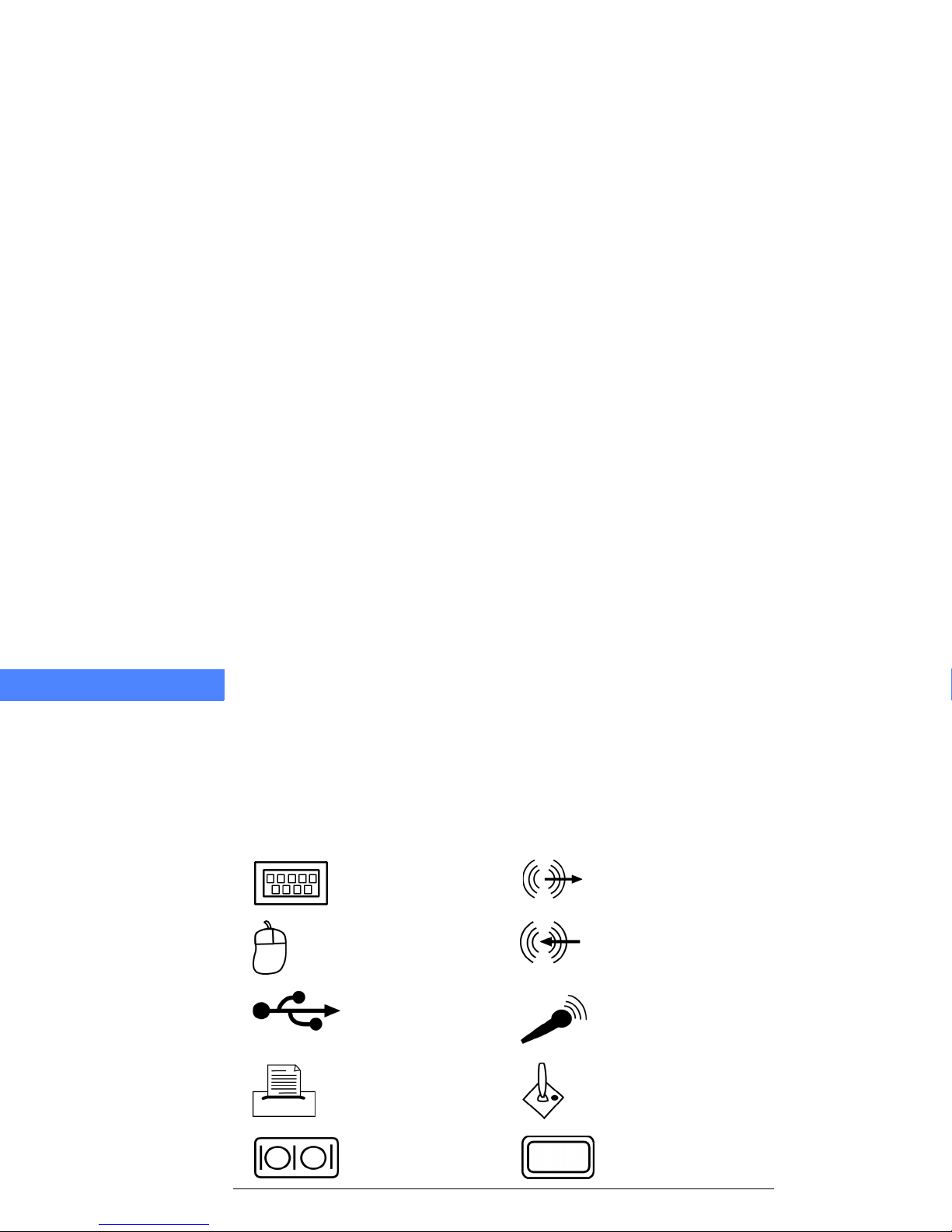
Table 6 provides illustrations of the component icons that are located on the rear panel of the
computer.
Tab le 6: Component Icon Description
......
Icon
........
Component
......
Icon
........
Component
Keyboard Audio Out
Mouse Audio In
USB connector Microphone
Parallel Printer Port Game Port
Serial Port Analog Monitor Port
Page 23

5-23
.....
...................................
S
ETTING
UPY
OUR
C
OMPUTER
5
.................................................................
CONNECTING THE COMPONENTS
This section provides instructions for connecting the following components:
•
keyboard
•
mouse
•
monitor
•
speakers
•
modem line
Each plug-end and port are color-coded. As you follow these instructions, verify that the plugend color and the port color are the same.
Page 24
SETTING UP YOUR COMPUTER
Connecting the Components
5-24
5
Note
...........................................
Most computer connections are “keyed” so that they can only be plugged in one way. If a connector does
...........................................
not plug-in easily, do not force it, double-check that the connector is lined up properly.
1 Place your computer where it can easily be moved into position after all the connections have
been made.
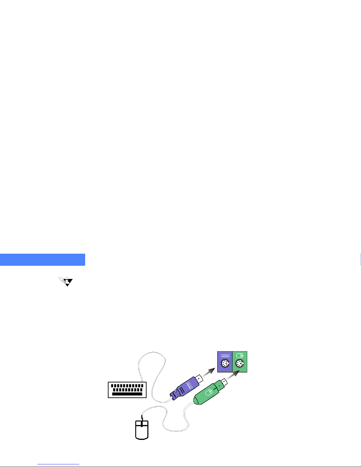
2 Plug in your keyboard and mouse as shown in Figure 3. If you have a USB keyboard or mouse,
you will need to plug them into the USB ports. See Figure 2, page 4 -21.
Figure 3. Connecting the Keyboard and Mouse
Page 25
SETTING UP YOUR COMPUTER
Connecting the Components
5-25
.....
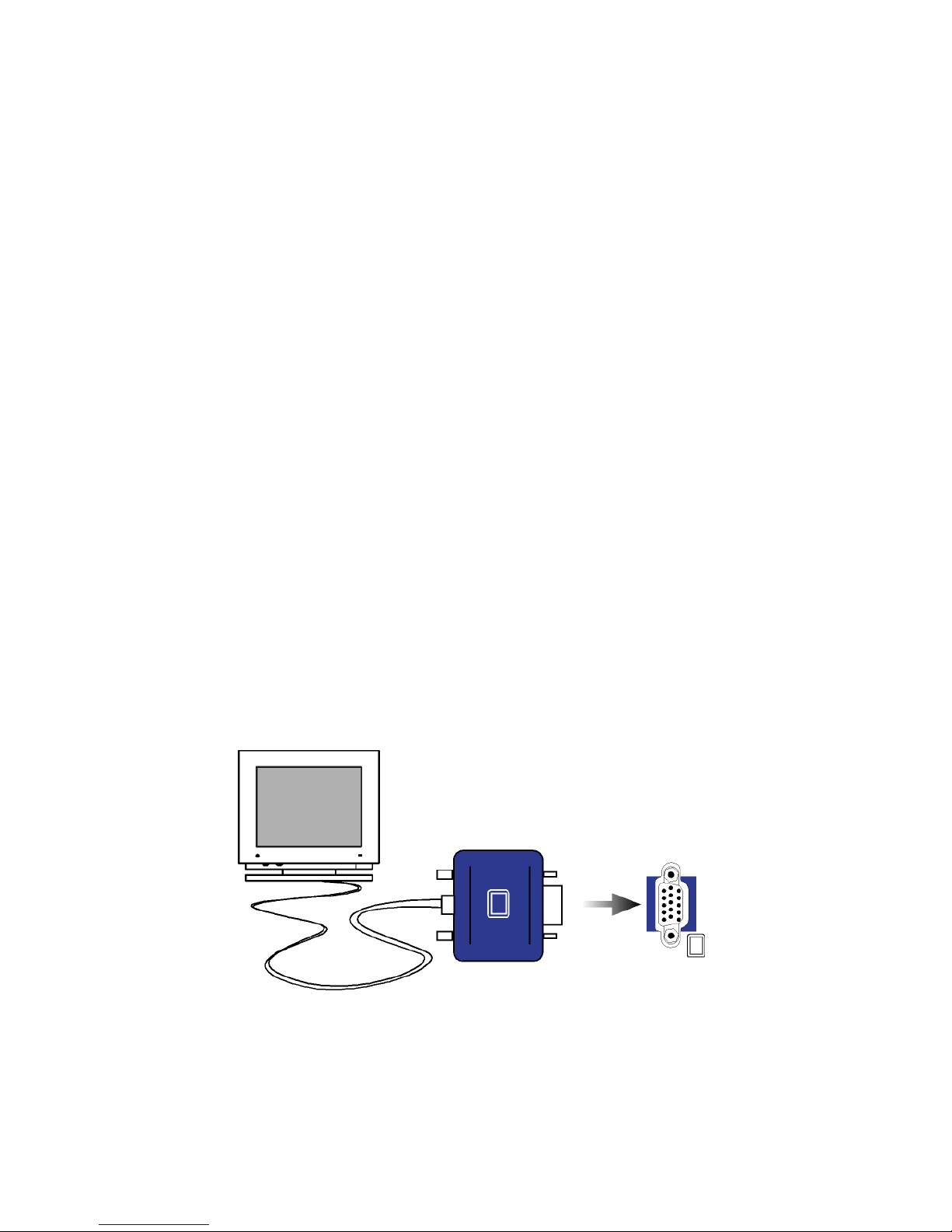
3 Plug the monitor cable (blue plug-end) into the monitor port (blue).
Figure 4. Connecting the Monitor
4 Secure the connection by tightening the screws on both sides of the monitor plug-end.
Page 26
SETTING UP YOUR COMPUTER
Connecting the Components
5-26
5
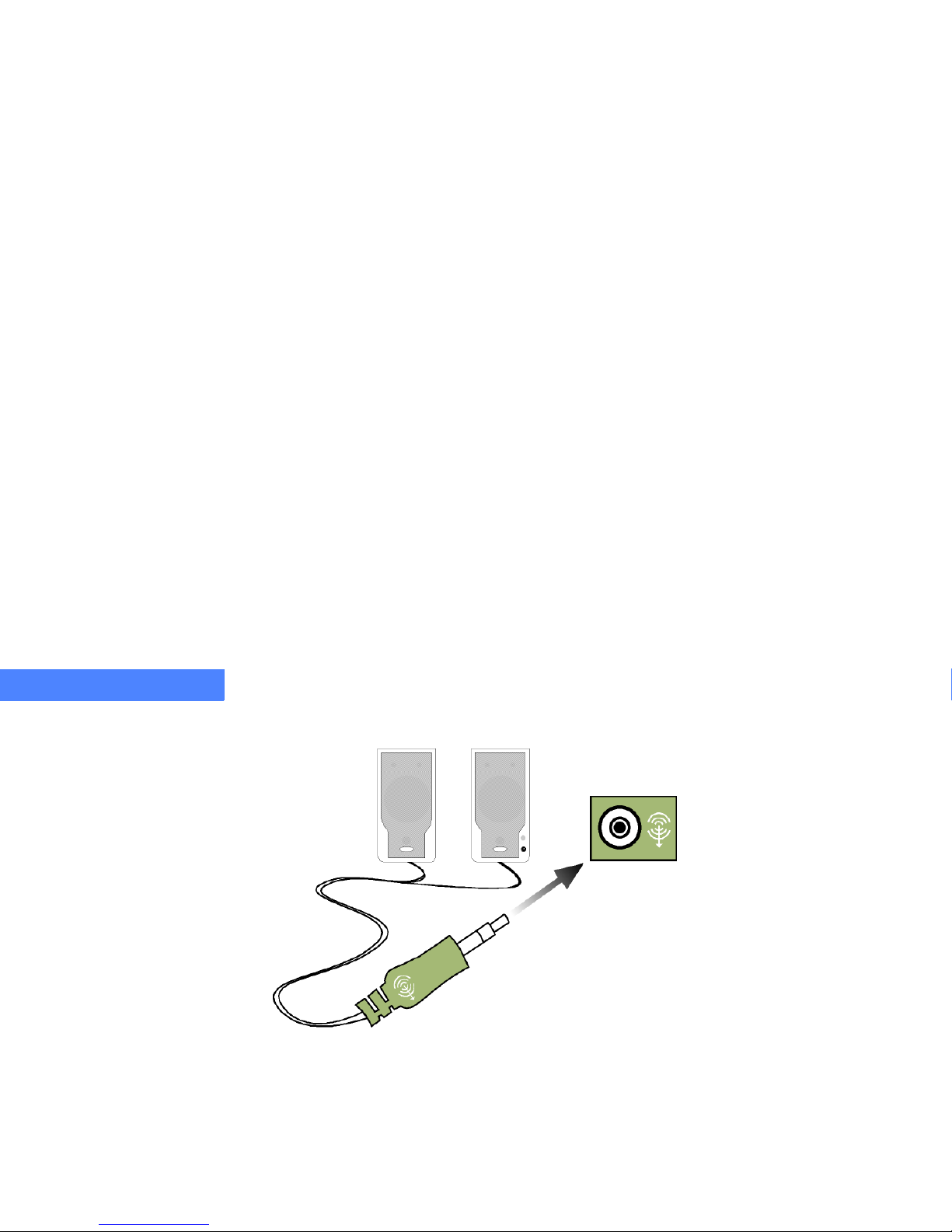
5 Connect the speaker cable (lime plug-end) to the audio-out jack (lime).
Figure 5. Connecting the Speakers
Page 27
SETTING UP YOUR COMPUTER
Connecting the Components
5-27
.....
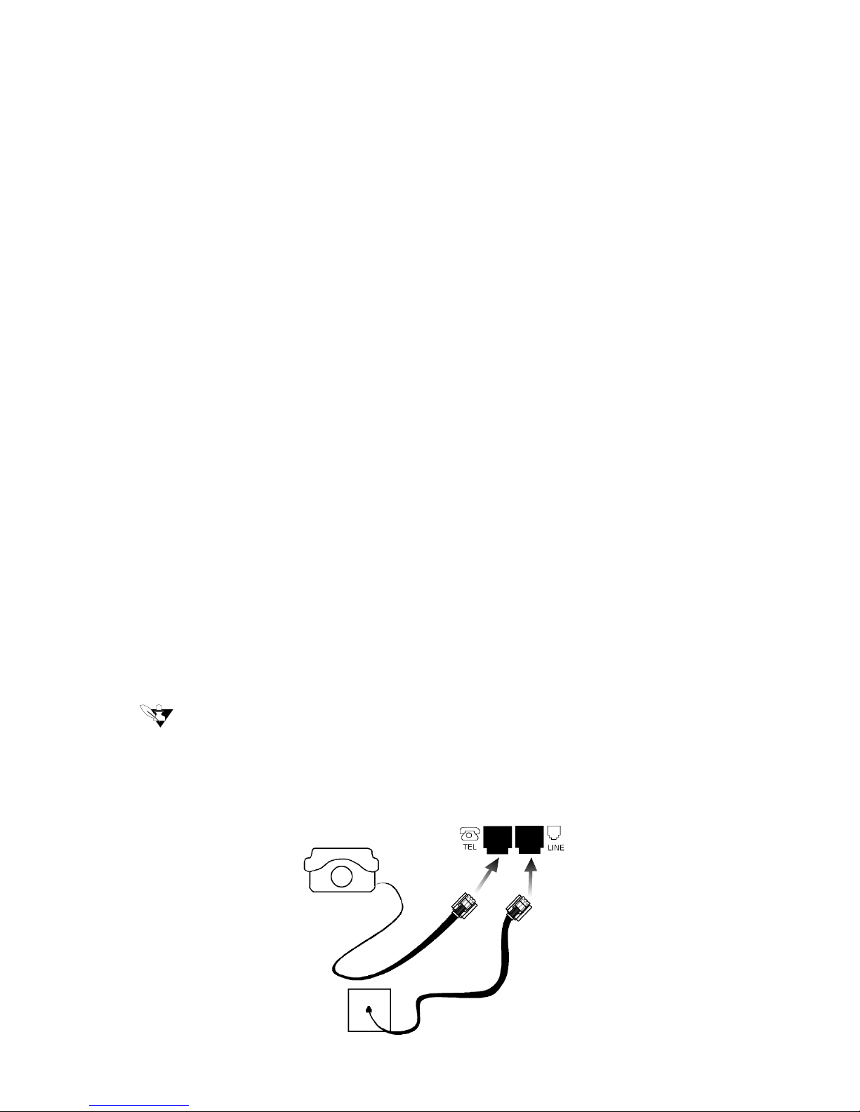
6 Connect the modem cable to a wall jack that has telephone access and plug the opposite end in
the modem line jack. Do not plug the modem into a digital wall jack (i.e. PBX system).
Note
...........................................
If you are using the wall jack your phone was connected to, or want to use an additional phone, plug the
phone into the computer’s phone jack. (This is optional, the modem will operate normally without a phone
...........................................
plugged into the computer’s phone jack.)
Figure 6. Connecting the Phone and Modem
Page 28
SETTING UP YOUR COMPUTER
Connecting Power to Your System
5-28
5
...................................................................
CONNECTING POWER TO YOUR SYSTEM
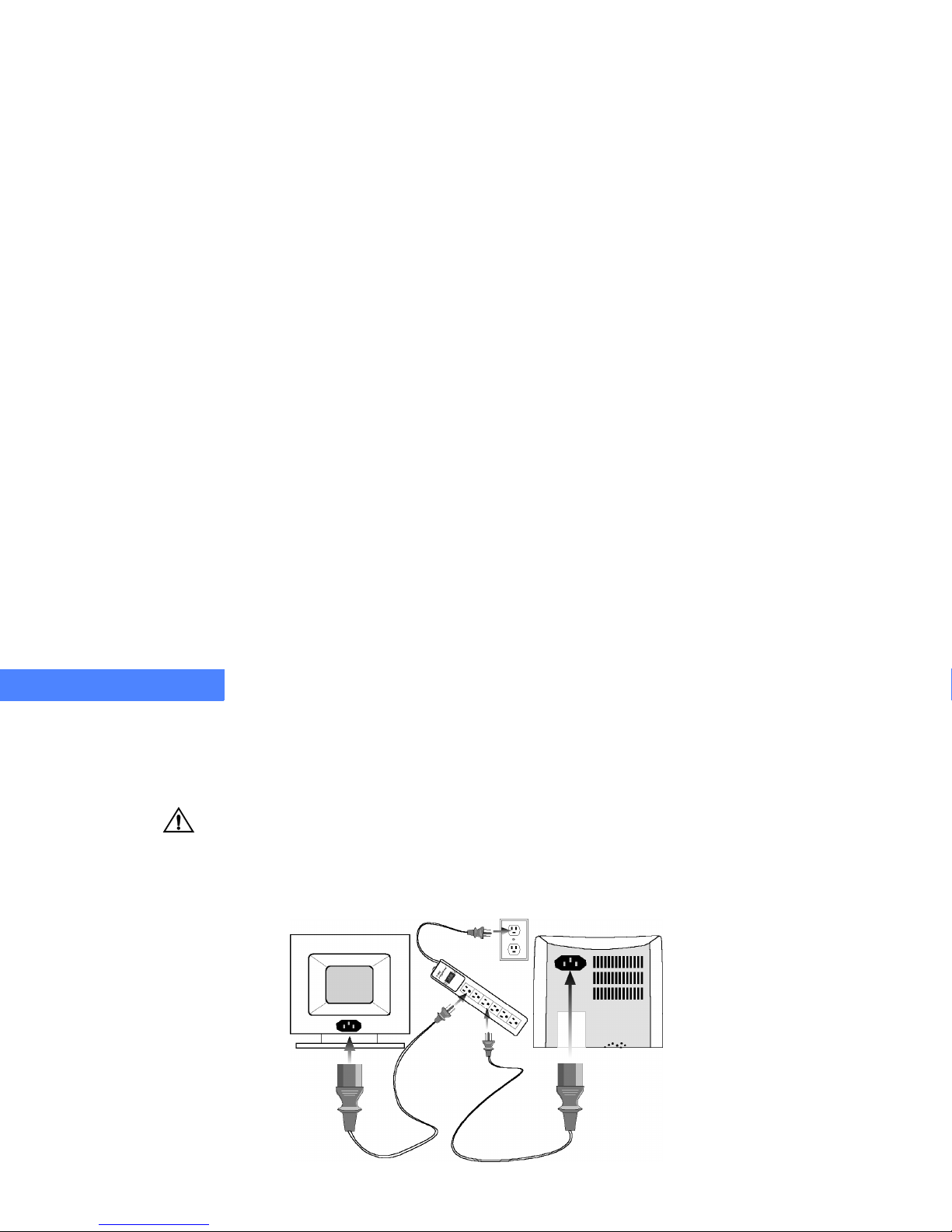
After you have connected the keyboard, mouse, monitor, speakers, and modem, connect the AC
power supply.
Caution
...........................................
To avoid damage to the system’s components caused by electrical surges, plug your system into a
surge protector. During an electrical storm, unplug both the surge protector from the power outlet
...........................................
and the telephone line from the phone jack.
Figure 7. Connecting the A/CPower
Page 29

6-29
.....
...................................
T
URNING
ONY
OURSYSTEM
6
.................................................................
RUNNING YOUR SYSTEM FOR THE FIRST TIME
Once you have completed the setup procedures, attached all components (i.e. mouse,
monitor, keyboard, etc.), and connected your computer and monitor to AC power, you are
ready to power up the system.
To turn on your system, complete the following steps:
1 Apply power to the monitor. If you are unsure about this, please refer to the monitor’s manual
for more information.
2 Apply power to the speakers. If you are unsure about this, please refer to the speaker’s
manual for more information.
Page 30
TURNING ON YOUR SYSTEM
Running Your System for the First Time
6-30
6
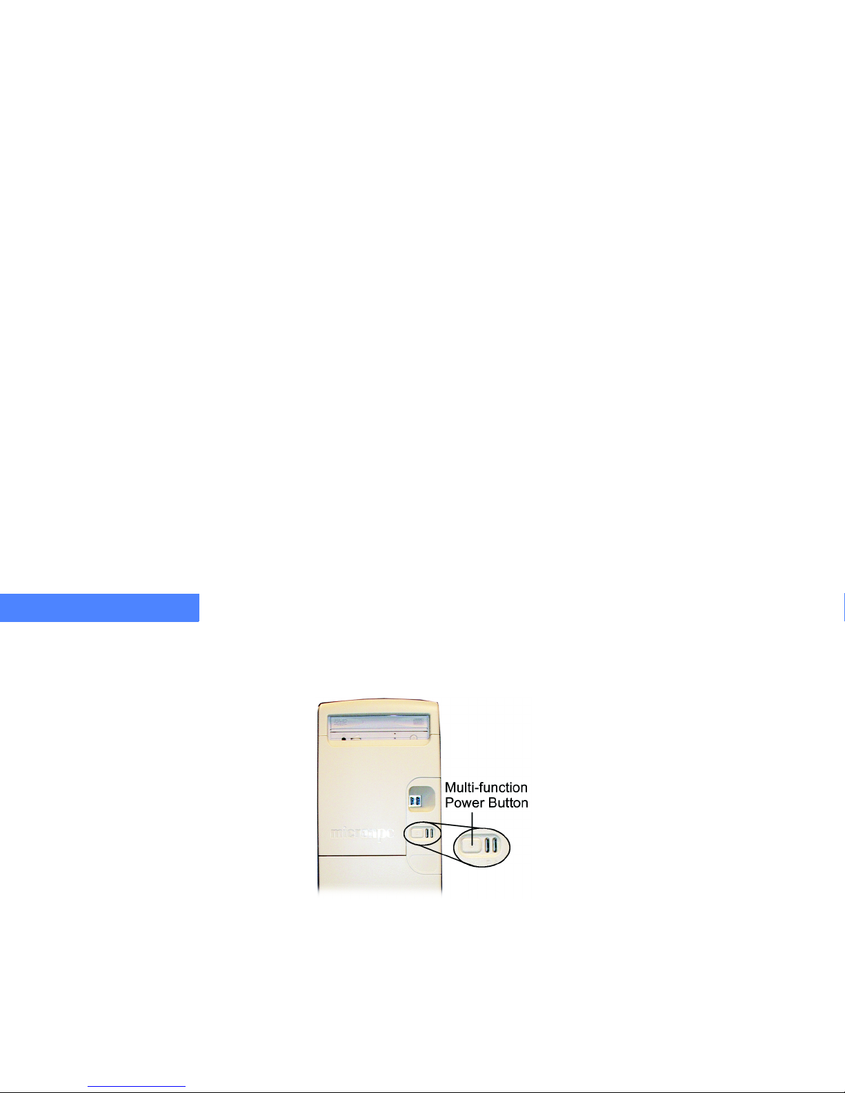
3 Apply power to the computer system by firmly pushing and releasing the multi-function power
button on the front panel. The power indicator LED will illuminate, the disk drive LED will blink,
and the disk drive and power supply fan will begin to run.
Figure 8. Multi-function Power Button
Once you have turned on the computer, the hardware diagnostics begin to run. The keyboard is
then initialized, indicated by the keyboard LEDs blinking. Next, the screen initializes and displays
the MicronPC splash screen.
4 Several tests occur while the splash screen is displayed. To view the tests, press the [Tab] key on
your keyboard. After the tests finish running, the system boots and the operating software system
screen appears.
Page 31

TURNING ON YOUR SYSTEM
Running Your System for the First Time
6-31
.....
5 The first time you turn on your computer, a series of Microsoft
Windowsstartup screens will
appear. Follow the on-screen instructions.
6 If you are prompted for the Product ID number, refer to the Certificate of Authenticity label on
your computer.
Note
...........................................
If you experience problems during the power on sequence, please refer to the Troubleshooting Appendix,
A-115. If you turn off your computer without following the proper turn on/off steps, Windows 98 and Me will
open Scandisk (Windows 2000 and XP will open CHKDSK) next time you turn on your system. Follow the
...........................................
directions displayed on the monitor to avoid data loss.
Internet Access
The setup program may prompt you to sign up for Internet access. You have the option to sign up
now or at a later time. For more information about the Internet, refer to “Internet Overview” on
page 7-41.
Page 32

TURNING ON YOUR SYSTEM
Running Your System for the First Time
6-32
6
Standby Mode
Note
...........................................
...........................................
This section applies only to operating systems that provide the power management option.
Standby mode reduces the power consumption of your system. Depending on your operating
system (OS), your system may have been configured at the factory to enter standby mode
(indicated by the power LED changing from green to red) if one of the following events occur:
•
There is no mouse or keyboard usage for the time defined in the Power Options
Properties dialog box. To modify the time the system takes to enter standby mode, refer to
“Modifying Standby Mode Settings” on page 6 -34.
•
The multi-function power button is pressed for less than 4 seconds. If you re-install
Windows, you will need to change this setting back to the factory default. Refer to
“Modifying Standby Mode Settings” on page 6 -34.
•
Standby mode is manually entered:
a. Click the Start button.
b. Select Shut Down (for Windows XP select Turn Off Computer).
c. When the Shut Down Windows dialog box appears, select Stand By and click OK.
•
The Sleep/StandBybuttononthekeyboardispressed(optional feature). If you re-
install Windows, you may need to change this setting back to the factory default. Refer to
“Modifying Standby Mode Settings” on page 6 -34.
Page 33

TURNING ON YOUR SYSTEM
Running Your System for the First Time
6-33
.....
Regardless of how your system entered standby mode, you can return your computer to normal
operation by doing one of the following:
•
pressing the multi-function power button
•
pressing any key on the keyboard
Note
...........................................
...........................................
Wait approximately 30 seconds before attempting to open files or start programs.
Caution
...........................................
...........................................
Disconnecting power from your system while in standby mode may result in data loss.
Page 34

TURNING ON YOUR SYSTEM
Running Your System for the First Time
6-34
6
MODIFYING STANDBY MODE SETTINGS
1 Click the Start button.
2 Choose Settings, and select Control Panel.
3 Follow the instructions below based on the operating system installed on your computer.
•
For Windows 98 and NT systems, double-click Power Management.ThePower
Management Properties dialog box will appear.
•
For Windows Me and 2000 systems, double-click Power Options.ThePower Options
Properties dialog box will appear.
•
For Windows XP systems, double-click Performance and Maintenance. Then double-click
Power Options.ThePower Options Properties dialog box will appear.
4 Modify the power management settings to your specifications.
The Advanced tabinthePower Options Properties dialog box contains security and display
options. You can also specify the mode of power management your computer goes into when the
power button or the sleep button is pressed. Depending on which version of Windows is installed
on your computer, you can choose to have your system go into one of the following power saving
modes: standby, hibernate, or off.
For more information on the specific power saving modes, refer to the Microsoft Windows manual
or to Windows Help (Press [F1]) for specific instructions about your operating system.
Page 35
TURNING ON YOUR SYSTEM
Running Your System for the First Time
6-35
.....
Light Emitting Diodes (LEDs)
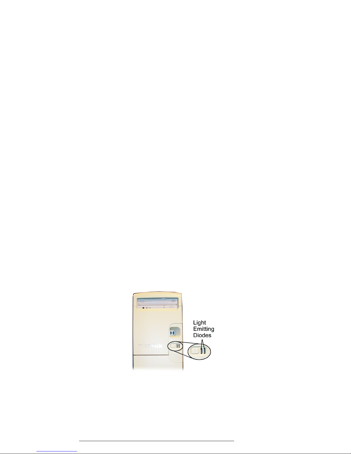
Your system is equipped with two light emitting diodes (LEDs), which provide feedback during
system operation.
Figure 9. Light Emitting Diodes
Tab le 7: LED Indication Colors
....
Color
...........
Indication
Right LED
Green System Power On
Red Standby Mode
Left LED
Amber Hard Disk Drive Activity
Page 36

TURNING ON YOUR SYSTEM
Turning Off Your System
6-36
6
...................................................................
TURNING OFF YOUR SYSTEM
You may leave your system running for extended hours, but when you do need to power off,
MicronPC recommends you follow these steps:
1 Save any work you want to keep and exit all open applications.
2 Make sure that ALL disk activity has completely stopped. The floppy and hard disk drive LEDs
should be off, and the floppy drive motors should stop.
3 Refer to the Microsoft Windows manual or online help for instructions specific to the operating
system you are using.
Caution
...........................................
Avoid turning off the system by pushing the multi-function power button. This will erase unsaved
material and may leave some files open that can be corrupted the next time you turn on your
system. If your system locks up or is unresponsive, try a warm reboot [Ctrl+Alt+Del] before
...........................................
manually turning off the computer.
Page 37

TURNING ON YOUR SYSTEM
Turning Off Your System
6-37
.....
Manual Shutdown
To manually shutdown your system, press and hold the multi-function power button for more than
5 seconds.
There are only two situations where you should use the manual shutdown procedure:
•
Your system has encountered a software error and has failed to respond to any user input
including [Ctrl+Alt+Del].
•
The system was booted into command prompt mode (operating system specific).
Caution
...........................................
If you have not encountered one of these situations, shut down the system through the operating
...........................................
system shut down function to avoid data loss.
Note
...........................................
If you turn off your computer without following the specific steps for your operating system, the operating
system may open Scandisk (Windows 2000 and XP will open CHKDSK) the next time you turn on your
...........................................
system. Follow the directions displayed on the monitor to avoid data loss.
System Reset
If applications are open or if the disk drive is active and the system is manually shutdown, data
loss will occur. Make sure the disk drive has completely stopped before turning on the computer.
Page 38

TURNING ON YOUR SYSTEM
Restarting Your System
6-38
6
...................................................................
RESTARTING YOUR SYSTEM
Caution
...........................................
If possible, do not turn the system on and off frequently. This stresses the power supply and may
...........................................
shorten the life of some components.
Refer to the Microsoft Windows manual and online help for instructions specific to the operating
system you are using.
...................................................................
BACKING UP YOUR SYSTEM
Even with today’s technology, data loss can occur at any time. We highly recommend that you
back up data files often. A large number of backup systems are available from retail and mailorder outlets, which include removable disk drive backup systems, tape backup systems, and
optical backup systems. Complete and frequent backups can save years of data from total and
irretrievable destruction.
Page 39

TURNING ON YOUR SYSTEM
Ergonomic Tips
6-39
.....
...................................................................
ERGONOMIC TIPS
As you begin to personalize your working environment, it is important to keep your body’s needs
in mind. Doing so will make your computer time more productive with less physical and mental
stress. This section offers some suggestions for setting up an effective work area.
Setting Up Your Workstation
•
Adjust your chair so that your feet rest on the floor. The backrest should offer firm support
for your back, especially your lower back.
•
Position your monitor so that it is 18 to 24 inches away from your eyes (longer distances
relax the eyes). The top of the monitor should be level with your eyes.
•
Place your keyboard at approximately elbow height. Wrists should be in a neutral position.
Keep your wrists straight and relaxed, and always operate the keyboard with a light touch.
•
Keep the mouse within easy reach, and alternate between using the mouse and keyboard.
Sitting At Your Workstation
•
Maintain a relaxed posture.
•
Avoid excessive reaching when you are working at your computer. Supplies should be
within easy reach.
•
Use your whole arm to move the mouse.
•
Minimize hand and elbow contact with hard or sharp surfaces.
Page 40

TURNING ON YOUR SYSTEM
Ergonomic Tips
6-40
6
Maintaining a Comfortable Workstation
•
Keepdustintheareatoaminimum.
•
Maintain a comfortable room temperature.
Reducing Eye Strain
•
Eliminate or reduce screen glare.
•
Avoid sunlight or bright light shining directly on your screen or your eyes.
•
Focus your eyes away from the monitor frequently and do not forget to blink.
•
Avoid excessive repetition by varying your activities.
Performing Exercises
•
Take short breaks and deep breaths frequently.
•
Stretch your arms or let them fall relaxed at your sides and shrug your shoulders.
•
Stretch your muscles.
•
Shift positions as frequently as possible.
Page 41

7-41
.....
...................................
U
SINGYOUR
C
OMPUTER
7
Now that your system is set up, you are ready to start using your computer. This section
provides a basic overview and some tips about using the Internet and e-mail. It also provides a
general description of the keyboard.
For detailed information about your computer’s operating system, refer to the Microsoft manual
that came with your system. For more detailed instructions about using the Internet and
e-mail, refer to the instructions provided by your Internet Service Provider (ISP).
.................................................................
INTERNET OVERVIEW
The Internet is a world wide electronic communications network that connects computer
networks around the world using cables or phone lines. The World Wide Web (WWW) is the
best-known part of the Internet. Multimedia files consisting of text, graphics, audio, and video
characterize the WWW.
Page 42

USING YOUR COMPUTER
Internet Overview
7-42
7
Internet Service Provider
To get connected to the Internet, you need an Internet service provider (ISP), which is a company
that provides access to the Internet.
UsingaWebBrowser
In order to view files on the Web, you need Web browsing software. A Web browser is a
computer program that enables a user to access and view Web sites on the Internet. To begin
surfing the Internet, you need to open a Web browser such as Internet Explorer.
Surfing Tips
To surf the Internet you will need to log on to an ISP. Once you are logged on and your Web
browser is launched, you can:
•
type in Internet addresses (URL’s)
•
click on hyperlinks
•
search the Internet for a wide range of information
INTERNET ADDRESSES (URLS)
Every page of the Internet is assigned a Uniform Resource Locator (URL), which is an Internet
address that identifies the location of any Web page. The best way to surf the Internet is by typing
aURLintotheAddress bar of your Internet browser.
For example, typing the address (or URL)
www.micronpc.com
accesses MicronPC’s Web site
and all its associated Web pages.
Page 43

USING YOUR COMPUTER
E-mail Overview
7-43
.....
HYPERLINKS
Another way to navigate from one Web page to another is by clicking on a hyperlink. A hyperlink
is a clickable connection using words or pictures. A hyperlink is a form of navigation that displays
different Internet sites or Web pages. Your cursor will change appearance when your mouse
pointer moves over a link.
SEARCHING THE INTERNET
To make your search easier, follow these steps:
•
Be as precise as possible. You can search for any type of information.
•
Type the word or phrase you are looking for and click Search or [Enter].
•
When the list of possible sites and descriptions appears, click the desired hyperlink.
...................................................................
E-MAIL OVERVIEW
You can communicate electronically over the Internet with friends, family, and colleagues. You
will need e-mail software, such as Microsoft Outlook, and an e-mail account in order to send and
receive e-mail. For details on getting an e-mail account, contact an Internet Service Provider (see
"Internet Service Provider" on page 7 -42).
Page 44

USING YOUR COMPUTER
Keyboard Overview
7-44
7
...................................................................
KEYBOARD OVERVIEW
A keyboard is a hardware device consisting of keys which, when pressed, input characters into a
computer. There are four essential elements on a standard keyboard.
•
alphanumeric typing keys
•
function keys
•
numeric keys
•
arrow keys
Table 8 lists special functional keys that exist on the keyboard and their functions.
Tab le 8: Special Keyboard Keys
..........
Key/Button
..............................
Description
Arrow Keys Directional keys that move the cursor left, right, up or down without
changing any data that has been entered.
Windows Start Opens the Start menu.
Page 45

USING YOUR COMPUTER
Keyboard Overview
7-45
.....
Windows Application Opens a drop-down menu. Can be used instead of a right mouse click.
Alt Performs functions when used in conjunction with other keys. For example:
[Ctrl+Alt+Delete].
Backspace Deletes the character one position left of the cursor when pressed.
Caps Lock Turns the Caps Lock on or off. When Caps Lock is on, characters are
entered in uppercase.
Ctrl Performs functions when used in conjunction with other keys. Usually used
for keyboard shortcuts. For example: [Ctrl+S] performs the Save function.
Delete Deletes the character to the right of the cursor and moves the following text
into that space.
End Moves the cursor to the end of the line that the cursor is positioned on.
Enter Begins a new line or paragraph.
Esc Reverses the action of another key, terminates dialog boxes, and closes
programs.
Function Keys Instructs application programs to perform certain actions by generating
short, fixed character codes.
Tab le 8: Special Keyboard Keys (Continued)
..........
Key/Button
..............................
Description
Page 46

USING YOUR COMPUTER
Keyboard Overview
7-46
7
Home Moves the cursor to the beginning of the current line that the cursor is
positioned on.
Insert Turns the Insert mode on or off. When Insert mode is on and keys are
pressed, characters are placed at the position of the cursor and all the
characters following the cursor are pushed to the right.
Num Lock Turns the Number Lock on or off. When Num Lock is on, the numeric
keypad can be used to enter numbers.
Page Up/Page Down Directional keys that move the page or screen up or down.
Pause Stops the screen temporarily from scrolling.
Print Scrn Prints the screen that is displayed to the clipboard.
Scroll Lock Controls how the cursor control keys work (depending on the program being
used).
Shift Performs functions when used in conjunction with other keys. For example:
[Shift+S] capitalizes the letter s.
Tab Moves the cursor to the next field.
Tab le 8: Special Keyboard Keys (Continued)
..........
Key/Button
..............................
Description
Page 47

8-47
.....
...................................
I
NSTALLINGSOFTWARE
8
.................................................................
INSTALLING ADDITIONAL SOFTWARE
After you have become familiar with the preinstalled software on your system, you may want to
install additional software. When looking for additional software, make sure that the software is
compatible with your Microsoft
Windowsoperating system and the specifications of your
computer.
Page 48

INSTALLING SOFTWARE
Installing Additional Software
8-48
8
Installing Software Automatically
When new software is installed, the software frequently includes its own install utility or
instructions. If this is the case, follow the on-screen installation instructions.
In the event that the new software does not include its own install utility or instructions, you can
install the software using the following instructions.
Installing Software from a CD or Floppy Disk
Follow these steps to install software from a CD or floppy disk that does not install automatically.
1 Close all open programs.
2 Click the Start button, select the Settings pull-down menu, and click Control Panel.
3 Double-click Add/Remove Programs.TheAdd/Remove Programs Properties window will
appear. Click Install.
4 Insert the CD or floppy disk into the primary drive
1
and click Next. The Microsoft Windows install
utility will locate the CD or floppy disk and begin the installation process.
1. If more than one of the same type of drive is in a system configuration, the primary drive is usually the top drive.
Page 49

INSTALLING SOFTWARE
Reinstalling Factory Software
8-49
.....
...................................................................
REINSTALLING FACTORY SOFTWARE
Most MicronPC systems include an
Operating System Recovery CD,aDrivers CD
,and
application and system software CDs so that you can reinstall the factory installed operating
system and programs.
Caution
...........................................
This process will overwrite all data currently on the hard disk drive and delete all data
...........................................
added after you received your system.
Operating System Recovery CD
This CD will install the original operating system that you received with your system. This will not
restore any additional programs installed at the factory or since you received your system.
To u se t h e
Operating System Recovery CD
, complete the following steps:
1 Insert the
Operating System Recovery CD
into the primary CD drive and restart your system. The
system will automatically read from the CD (user selection may be required) and display a startup screen that will lead you through the installation process.
2 Once you have completed the operating system installation, you will need to install the
appropriate drivers. Insert the
Drivers CD
into the CD drive, allow it to autorun, and follow the onscreen instructions. After the drivers have been installed, you can install application and system
software.
Page 50

INSTALLING SOFTWARE
Reinstalling Factory Software
8-50
8
Image Restore CD
Note
...........................................
...........................................
The Image Restore CD is not shipped with all system configurations.
The
Image Restore CD
will completely restore your computer to the condition it was in when you
first took it out of the box and turned it on. The
Image Restore CD
will automatically install all the
drivers and applications installed at the factory.
Caution
...........................................
This process will overwrite all data currently on the hard disk drive and delete all data
...........................................
added after you received your system.
To u se t h e
Image Restore CD
, complete the following steps:
1 Load the CD into the primary (usually the top) CD-ROM drive.
2 Restart your computer.
3 Follow the on-screen instructions that appear.
Page 51

9-51
.....
...................................
T
AKING
A
PARTYOURSYSTEM
9
To remove or replace peripherals and PCI cards, or add memory, you will need to remove the
computer panels to access the inside of the computer.
Caution
..........................................
Modules are Electrostatic Sensitive. A small electrostatic discharge (ESD) can damage computer
components. An ESD damaged module or PCI card might not fail immediately, but over time it
could become worse, possibly causing an intermittent problem. Be very careful to handle the
module or PCI card ONLY by the edges. DO NOT touch the gold/silver edge-connectors or any of
the components on the system board. Leave the module or PCI card in the antistatic bag until
..........................................
ready for installation.
Page 52

TAKING APART YOUR SYSTEM
Tools and Preparation
9-52
9
...................................................................
TOOLS AND PREPARATION
Disconnect the cables on the back of the computer before opening the access panel. For future
reference, note how the cables connect to the back of the system.
Caution
...........................................
The motherboard conforms to the new PCI 2.2 specification. This requires 3.3v standby for all PCI
slots, DIMM banks, and PS/2 outputs (KB/PS/2 Mouse). Always remember to unplug the AC power
cord before adding any PCI cards, memory, or plugging/unplugging the keyboard or mouse.
Otherwise, the system may automatically power up when adding the component. This could also
...........................................
damage the motherboard or the component you are adding and is not covered under warranty.
Electrostatic Discharge (ESD) Cautions
•
Leave the module in the antistatic bag until you are ready to install it.
•
The system should be opened on an ESD Safe Workbench, and the technician should wear
an ESD safe smock with grounding wrist and foot straps.
•
Keep DIMMs in the antistatic bag while transporting, especially when crossing carpet.
Antistatic wrist straps with clip-on ends are available commercially.
Page 53

TAKING APART YOUR SYSTEM
Removing and Replacing the Access Panel
9-53
.....
...................................................................
REMOVING AND REPLACING THE ACCESS PANEL
Caution
...........................................
...........................................
Be careful when handling access panels; they can be easily marred or scratched.
Removing the Access Panel
1 Turn off the computer. Refer to “Turning Off Your System” on page 6 -36.
2 Unplug the power cord from the power supply, or the computer could accidentally start.
3 Touch the metal case of the power supply or the metal lining of the computer chassis. This will
equalize electrical potential between your body and the case and help keep the modules or PCI
cards from being electrically damaged. Keep body movement to a minimum as you handle any
hardware components.
4 While facing the front of the system, gently lay the computer on its right side.
Page 54
TAKING APART YOUR SYSTEM
Removing and Replacing the Access Panel
9-54
9
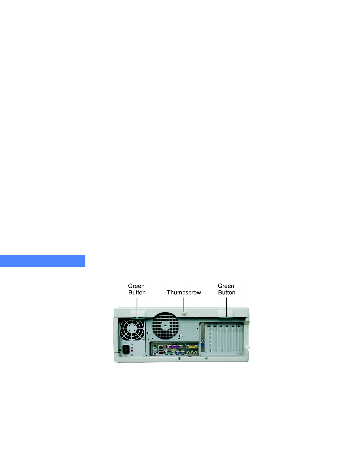
5 Face the back of the unit and locate the thumbscrew and the two green buttons.
Figure 10. Access Panel Thumbscrew and Green Buttons
6 Loosen the thumbscrew until it turns freely. Press both of the green buttons (Figure 10), and
remove the cover.
Replacing the Access Panel
1 Place the access panel onto the unit so the hooks in the cover engage with the corresponding
hooks under the front bezel. Pull the thumbscrew outward and push the panel onto the chassis; it
will click into place.
2 Tighten the thumbscrew (Figure 10).
Page 55
TAKING APART YOUR SYSTEM
Removing and Replacing the Bezel
9-55
.....
...................................................................
REMOVING AND REPLACING THE BEZEL
Removing the Bezel
1 Turn off the computer.
2 Unplug the power cord, or the computer could accidentally start.
3 Remove the access panel. See “Removing and Replacing the Access Panel” on page 9-53.
4 Stand the case upright.
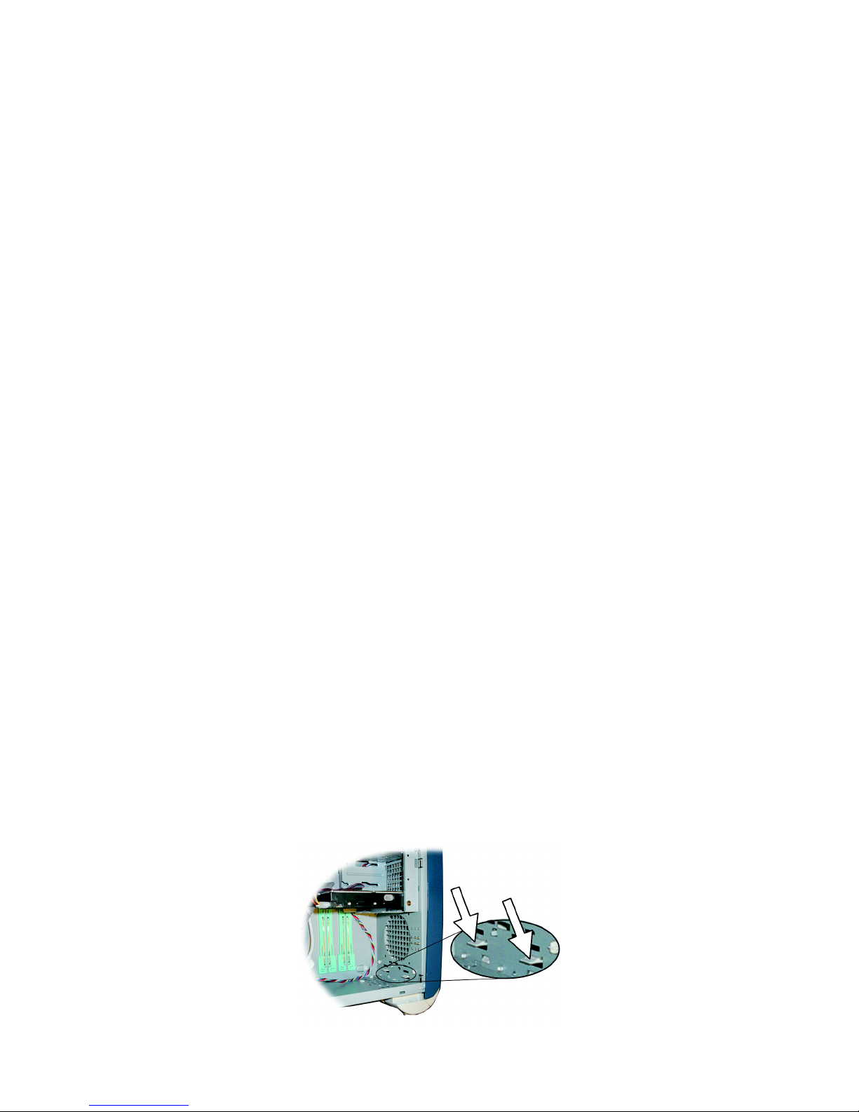
5 Press the two bezel release latches down, and then push them out (Figure 11).
Figure 11. Bezel Release Latches
6 Lift the bezel up and away from the case.
Page 56

TAKING APART YOUR SYSTEM
Removing and Replacing the Bezel
9-56
9
Replacing the Bezel
1 Face the front of the case.
2 Line up the top of the bezel with the case.
Figure 12. Lining up the Bezel
3 Swing the bezel down, and press the bottom against the case until it clicks into place.
4 Replace the access panel. See “Replacing the Access Panel” on page 9 -54.
Page 57
TAKING APART YOUR SYSTEM
Removing and Replacing the Bezel Door
9-57
.....
...................................................................
REMOVING AND REPLACING THE BEZEL DOOR
Removing the Bezel Door
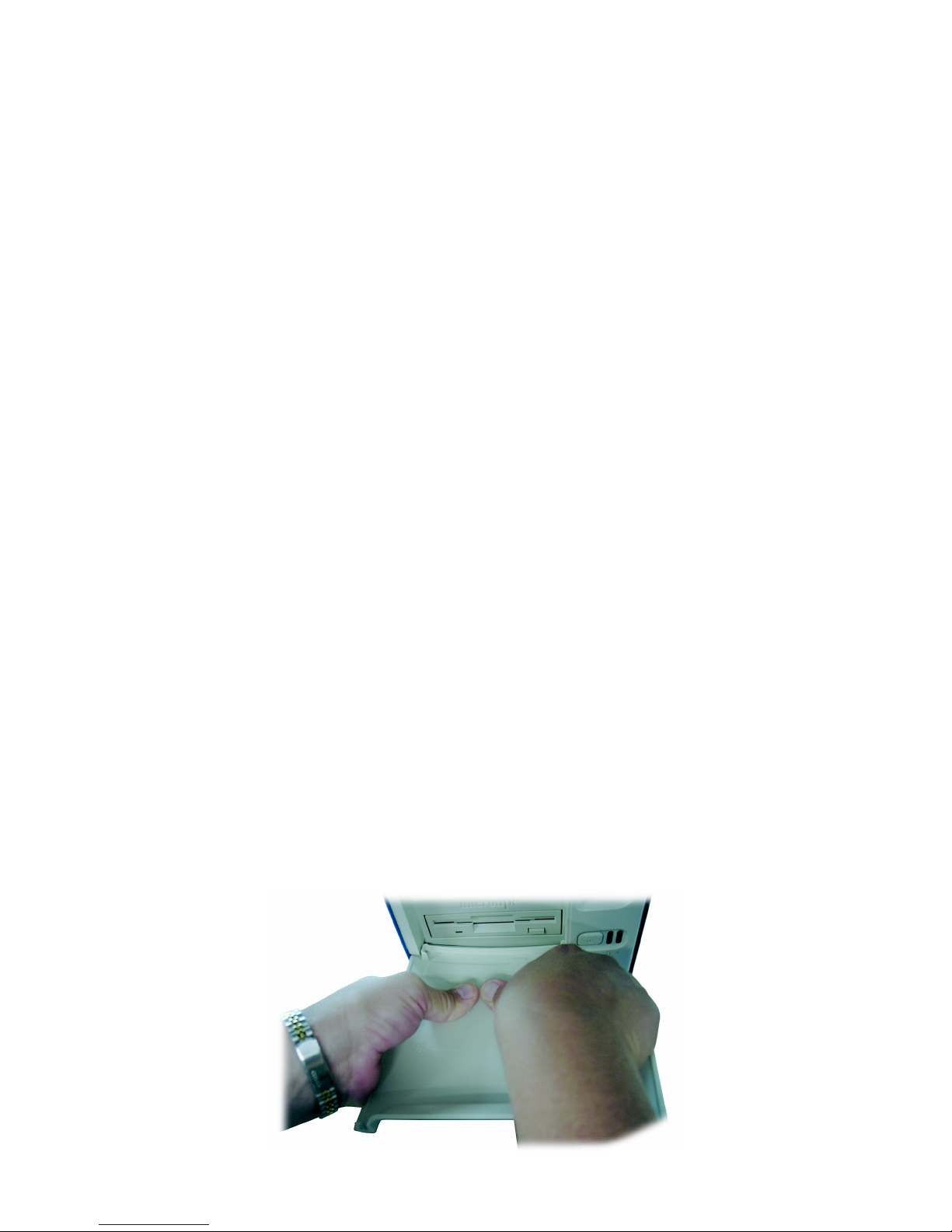
1 Face the front of the case, and open the bezel door.
2 Grasp both edges of the door and gently squeeze the edges inward so that the center bends
slightly. Then lift, do not pull, the left pivot point out of its socket, and lift the right pivot point out of
its socket to complete the removal.
Figure 13. Bezel Door
Page 58

TAKING APART YOUR SYSTEM
Removing and Replacing the Bezel Door
9-58
9
Replacing the Bezel Door
1 Insert the right pivot point into its socket. Then grasp both edges of the door, and gently squeeze
the edges inward so that the center bends slightly.
2 Insert the left pivot point into its socket, and close the door.
Page 59

10-59
.....
...................................
I
NSTALLING ANDREMOVING
H
ARDWARE
10
This chapter provides detailed instructions on how to install, remove, or replace the following
peripheral devices:
•
PCI and AGP cards
•
5.25-inch or 3.5-inch peripheral devices
•
hard and floppy disk drives
•
memory (DIMM) modules
•
power supply
Page 60

INSTALLING AND REMOVING HARDWARE
10-60
10
Caution
...........................................
Modules are Electrostatic sensitive. A small Electrostatic Discharge (ESD) can damage computer
components. An ESD damaged module or PCI card might not fail immediately, but over time it could
become worse, possibly causing an intermittent problem. Be very careful to handle the module or
PCI card ONLY by the edges. DO NOT touch the gold/silver edge-connectors or any of the
components on the system board. Leave the module or PCI card in the antistatic bag until ready for
...........................................
installation.
Caution
...........................................
The motherboard conforms to the new PCI 2.2 specification. This requires 3.3v standby for all PCI
slots, DIMM banks, and PS/2 outputs (KB/PS/2 Mouse). Always remember to unplug the AC power
cord before adding any PCI cards, memory, or plugging/unplugging the keyboard or mouse.
Otherwise, the system may automatically power up when adding the component. This could also
...........................................
damage the motherboard or the component you are adding and is not covered under warranty.
Note
...........................................
Although your system’s case is a Tool Free Mini Tower, some advanced removals and installations (such as
...........................................
hard drives, power supplies, and system boards) will require a Phillips screwdriver.
Page 61

INSTALLING AND REMOVING HARDWARE
Removing and Installing a PCI or AGP Card
10-61
.....
...................................................................
REMOVING AND INSTALLING A PCI OR AGP CARD
This system board features three PCI slots and one AGP slot. This section describes how to
remove or install a PCI or AGP card.
Removing a PCI or AGP Card
1 Turn off the computer. Refer to “Turning Off Your System” on page 6 -36.
2 Unplug the power cord from the power supply, or the computer could accidentally start.
3 Remove all external power, data, and/or audio cables from the system.
4 Touch the metal case of the power supply or the metal lining of the computer chassis. This will
equalize electrical potential between your body and the case and help keep the modules or PCI
cards from being electrically damaged. Keep body movement to a minimum as you handle any
hardware components.
5 Remove the access panel. See “Removing the Access Panel” on page 9 -53.
Page 62
INSTALLING AND REMOVING HARDWARE
Removing and Installing a PCI or AGP Card
10-62
10
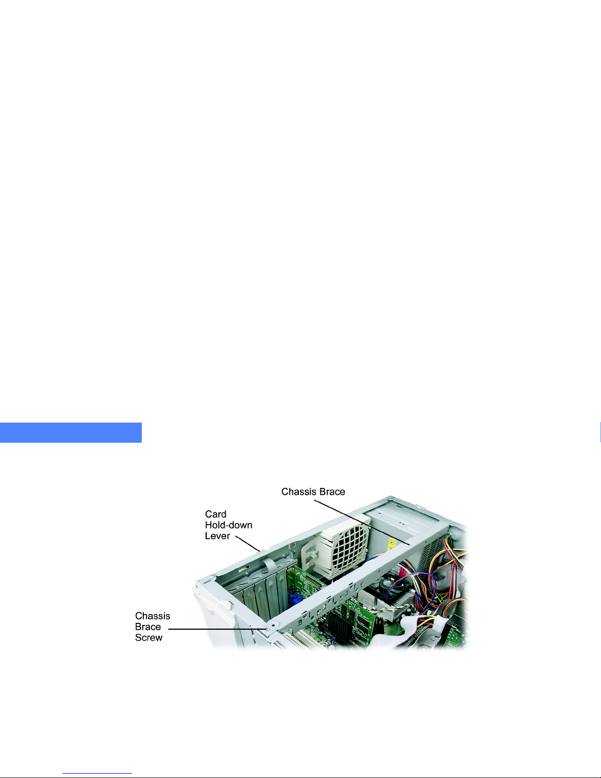
6 Remove the chassis brace (Figure 14) by removing the screw in the lower portion of the brace. If
there is no brace visible, it is not required for your configuration.
Figure 14. Overview of Card Devices
7 Lift up on the chassis brace (Figure 14), and remove it from the case.
8 Disengage the card hold-down rail by pushing the lever (Figure 14).
Page 63
INSTALLING AND REMOVING HARDWARE
Removing and Installing a PCI or AGP Card
10-63
.....
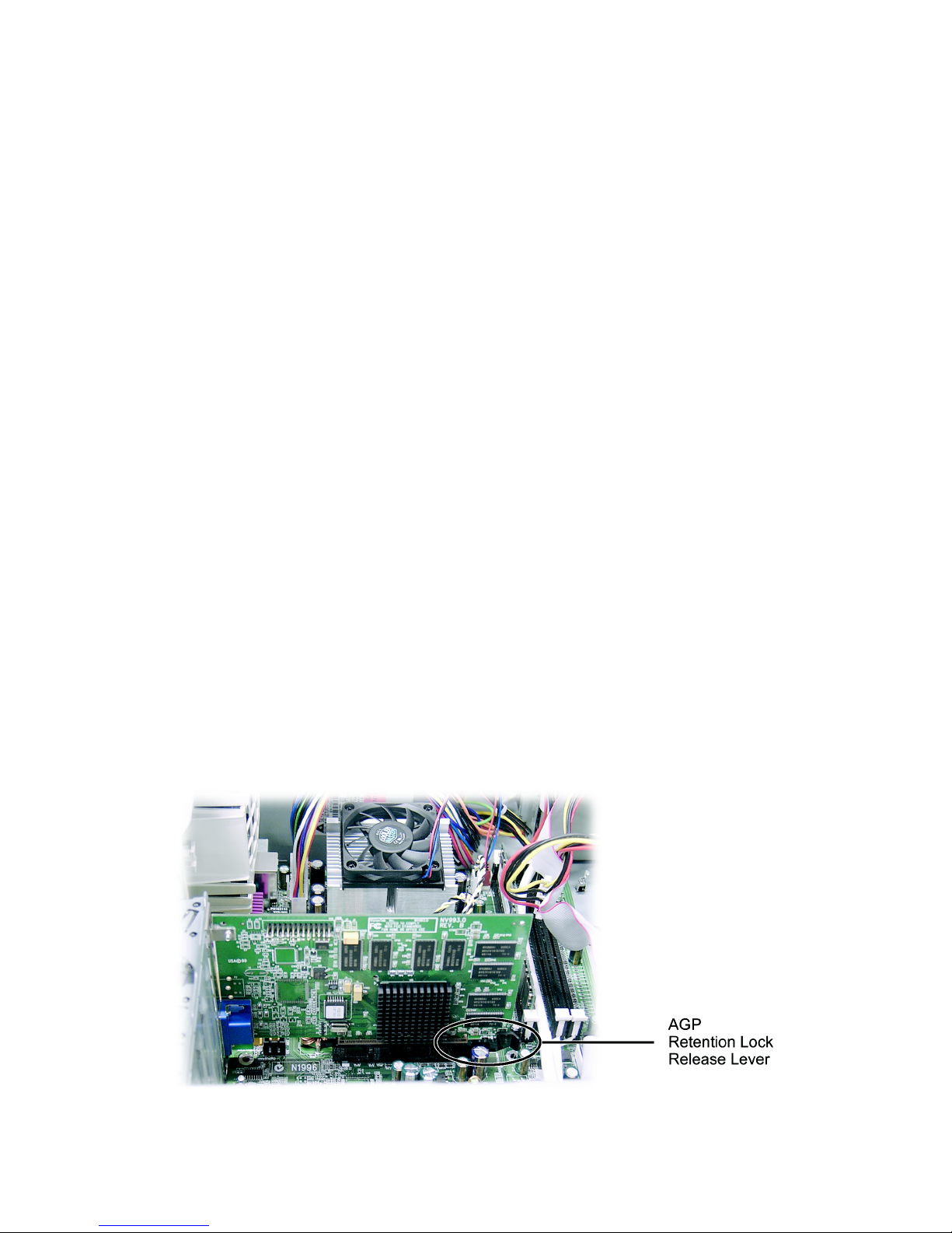
9 For PCI cards — grip the top edges of the card and pull to remove it from the slot.
For AGP cards — push the AGP retention lock release lever towards the bottom of the case with
your right hand, and then pull the card out with your left hand.
Figure 15. AGP Retention Lock Release Lever
Page 64

INSTALLING AND REMOVING HARDWARE
Removing and Installing a PCI or AGP Card
10-64
10
Installing a PCI or AGP Card
1 Remove the slot cover.
Figure 16. Removing a Slot Cover
2 Align the card with the slot and push down firmly until the card is seated. Repeat for all cards.
3 Re-engage the card hold-down rail (Figure 14, page 10 -62) by pushing upwards firmly on the
card hold-down lever until it snaps in place.
4 After replacing the card(s), re-install the chassis brace (Figure 14, page 10-62) and re-install the
screw into the bottom of the brace.
5 Replace the access panel. See “Replacing the Access Panel” on page 9 -54.
6 Reconnect all cables. Connect the power cable last.
Page 65

INSTALLING AND REMOVING HARDWARE
Removing and Installing Drives
10-65
.....
...................................................................
REMOVING AND INSTALLING DRIVES
This case has been designed for quick removal and replacement of drives. The drives (excluding
the floppy drive and hard disk drive) are secured by green rails. The hard disk drive (HDD) and
the floppy disk drive (FDD) are secured by screws. Use the following instructions to remove or
add a 3.5-inch or 5.25-inch drive and a HDD or FDD. In addition to these instructions, follow the
instructions that came with the drive you are installing.
Removing a 3.5-inch or 5.25-inch Drive
1 Unplug the power cord from the back of the power supply, or the computer could accidentally
start. Remove all external power, data, and/or audio cables from the system.
2 Remove the access panel. See “Removing the Access Panel” on page 9 -53.
3 Disconnect any power, data, or audio cables that may be connected to the drive.
4 Remove the bezel. See “Removing the Bezel” on page 9 -55.
Page 66
INSTALLING AND REMOVING HARDWARE
Removing and Installing Drives
10-66
10
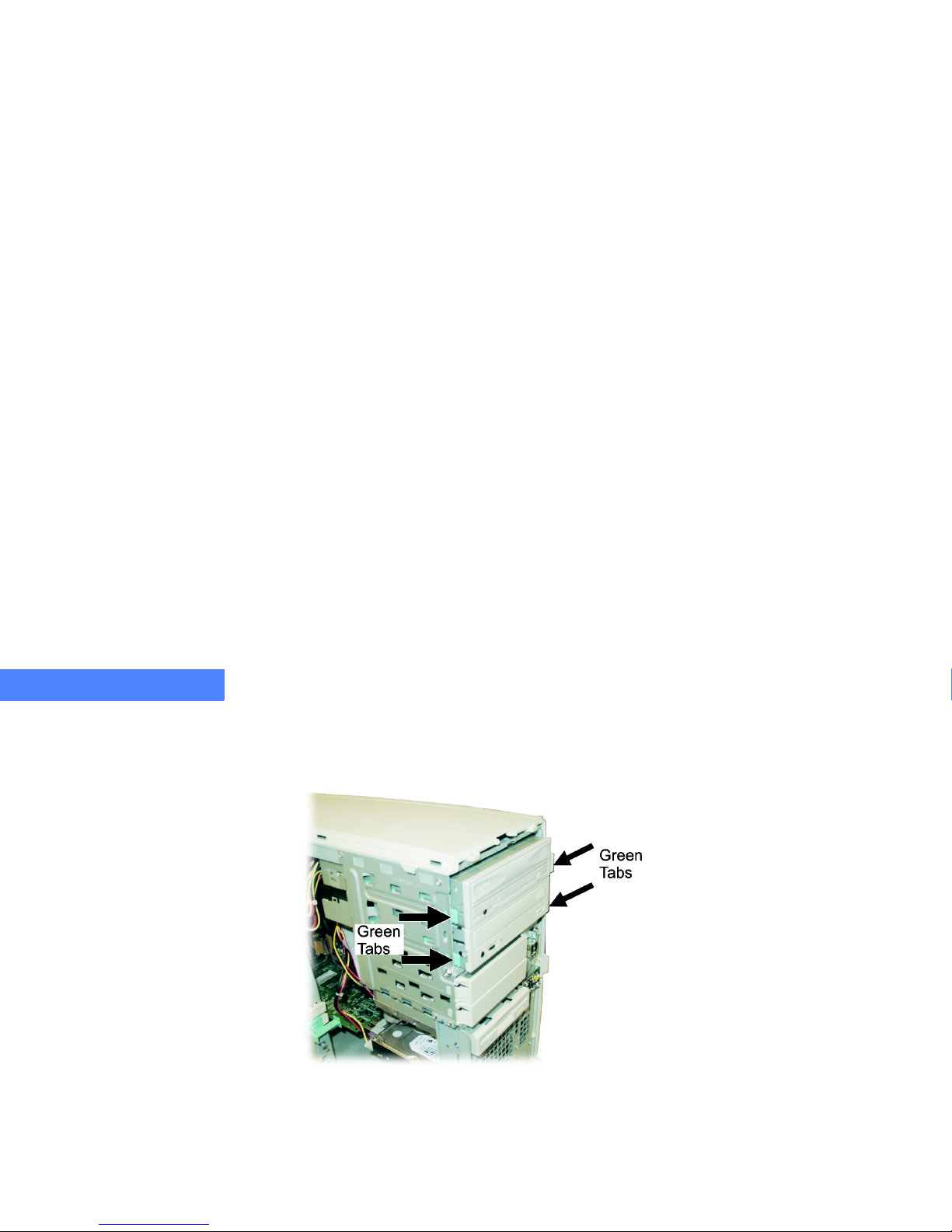
5 Remove the drive by squeezing the green tabs (Figure 17) on both sides of the drive and sliding
the drive out of the bay. It may be necessary to push the drive from the inside of the case with
one hand while holding the green tabs with the other.
Figure 17. Green Tabs on Drives
6 Remove the green rails by pulling them off the drive; they will snap free.
Page 67
INSTALLING AND REMOVING HARDWARE
Removing and Installing Drives
10-67
.....
Installing a 3.5-inch or 5.25-inch Drive
1 Remove the access panel. See “Removing the Access Panel” on page 9 -53.
2 Remove the bezel. See “Removing the Bezel” on page 9 -55.
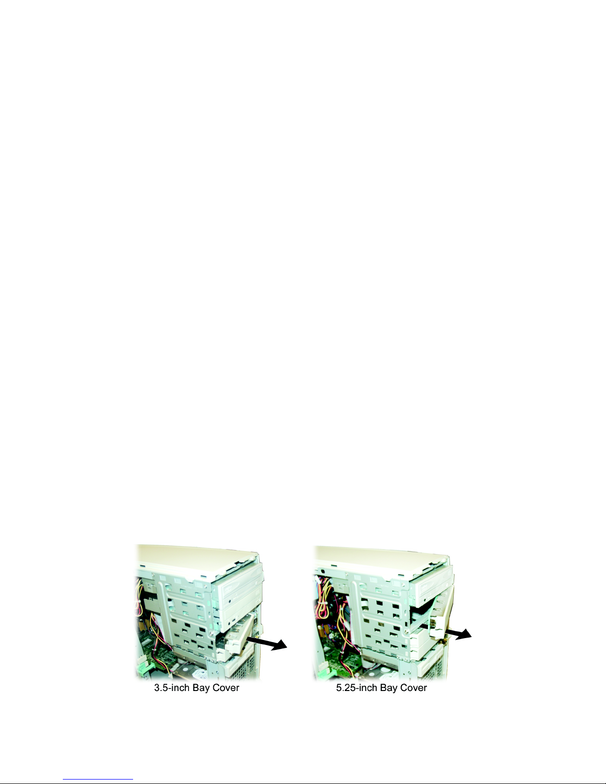
3 Remove the bay cover from the drive bay by pressing the plastic latch in and pulling the bay
cover free.
Figure 18. Removing the Drive Bay Covers
4 Remove the extra rails located inside the system under the hard drive (3.5-inch rail size) or on
the drive bay cover (5.25-inch rail size).
Page 68
INSTALLING AND REMOVING HARDWARE
Removing and Installing Drives
10-68
10
5 Attachtherailstothedrive.(The3.5-inchdriverailshaveanL or an R cut in them. Install the rail
with the L on the left side of the drive and install the rail with the R on the right side.)
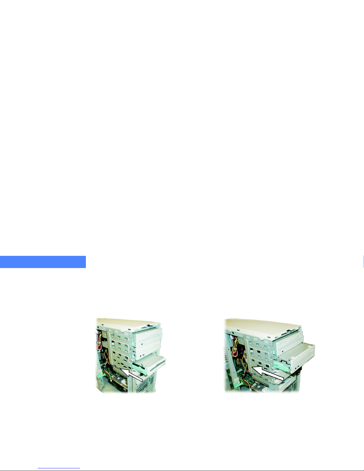
6 Slide the drive into the bay.
7 Reconnect any power, data, or audio cables to the drive.
8 Push the drive in evenly until it is fully seated, and the green rails snap into place.
9 Replace the bezel. See “Replacing the Bezel” on page 9-56.
10 Replace the access panel. See “Replacing the Access Panel” on page 9 -54.
Figure 19. Sliding the 3.5-inch Drive into the Bay Figure 20. Sliding the 5.25-inch Drive into the Bay
Page 69
INSTALLING AND REMOVING HARDWARE
Removing and Installing Drives
10-69
.....
Removing a Hard or Floppy Disk Drive
1 Unplug the power cord from the power supply, or the computer could accidentally start. Remove
all external power, data, and/or audio cables from the system.
2 Remove the access panel. See “Removing the Access Panel” on page 9 -53.
3 Disconnect any power, data, or audio cables that may be connected to the drive.
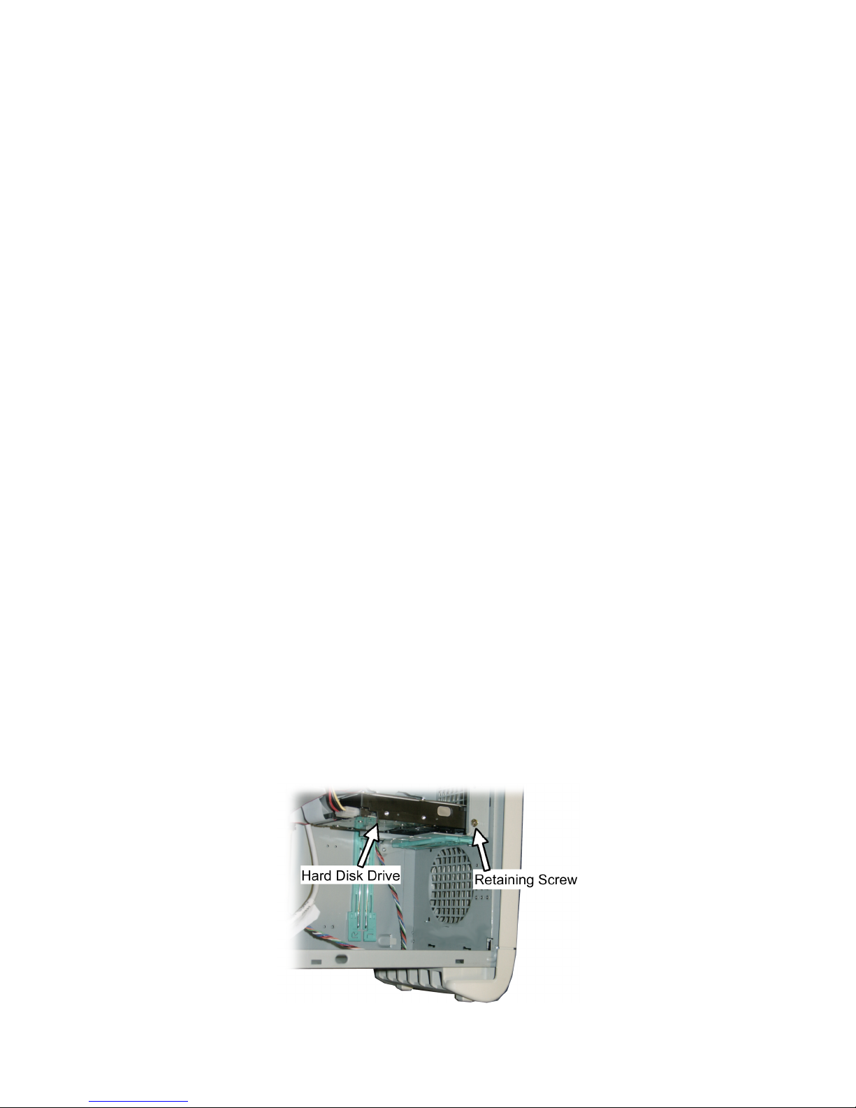
4 Remove the Phillips retaining screw that holds the drive in place (Figure 21).
Figure 21. Phillips Retaining Screw
5 Slide the drive toward the back about an inch. The screws on the opposite side of the drive
should clear the slots that hold them in place.
Page 70
INSTALLING AND REMOVING HARDWARE
Removing and Installing Drives
10-70
10
Installing a Hard or Floppy Disk Drive
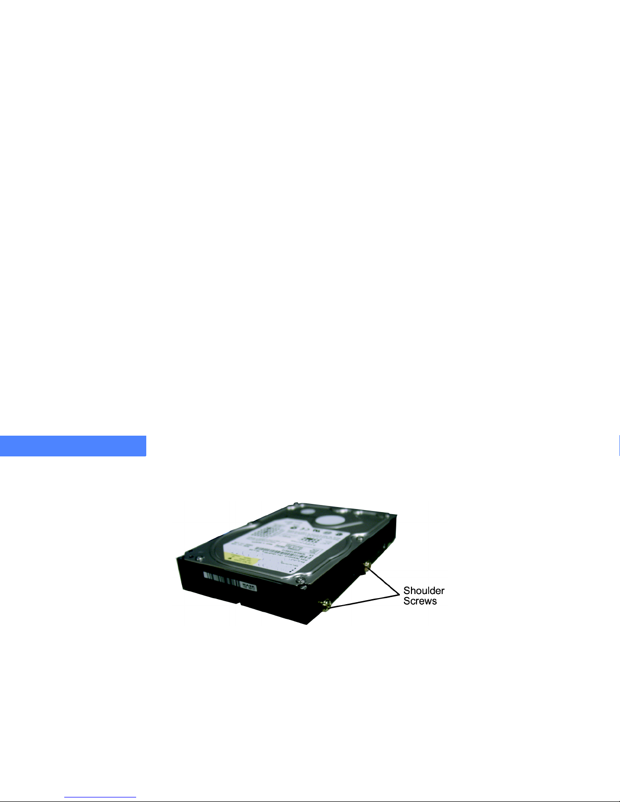
1 Attach the two shoulder screws.
Figure 22. Shoulder Screw Location
2 Slide the device toward the front of the case — making sure that the shoulder screws are
inserted into the slots.
3 Reconnect any power, data, or audio cables to the drive.
4 Install the Phillips standard retaining screw to secure the drive in place (Figure 21, page 10-69).
5 Replace the access panel. See “Replacing the Access Panel” on page 9 -54.
Page 71

INSTALLING AND REMOVING HARDWARE
Installing and Removing Memory
10-71
.....
...................................................................
INSTALLING AND REMOVING MEMORY
The system board has three double data rate (DDR) dual inline memory modules (DIMM)
sockets. The maximum amount of memory the system can hold is 3 GB (gigabyte).
Caution
...........................................
Modules are Electrostatic Sensitive. A small electrostatic discharge (ESD) can damage computer
components. An ESD damaged module or PCI card might not fail immediately, but over time it could
become worse, possibly causing an intermittent problem. Be very careful to handle the module or
PCI card ONLY by the edges. DO NOT touch the gold/silver edge-connectors or any of the
components on the system board. Leave the module or PCI card in the antistatic bag until ready for
...........................................
installation.
Caution
...........................................
The motherboard conforms to the new PCI 2.2 specification. This requires 3.3v standby for all PCI
slots, DIMM banks, and PS/2 outputs (KB/PS/2 Mouse). Always remember to unplug the AC power
cord before adding any PCI cards, memory, or plugging/unplugging the keyboard or mouse.
Otherwise the system may automatically power up when adding the component. This could also
...........................................
damage the motherboard or the component you are adding and is not covered under warranty.
Page 72

INSTALLING AND REMOVING HARDWARE
Installing and Removing Memory
10-72
10
When adding or changing memory, keep in mind that your computer supports the following:
•
184-pin unbuffered DIMMs
•
PC1600 — only for use with 200 MHz FSB processors
•
PC2100 — for use with 200 MHz and 266 MHz FSB processors
When all banks are filled with maximum memory, your computer will have up to 3 GB of DDR
SDRAM.
Installing DIMM Modules
The system board has three DIMM sockets. DDR synchronous dynamic random access memory
(SDRAM) can be installed in either one, two, or three sockets. There are no jumper setting
changes required for the memory size or type, which is automatically detected by the system
BIOS.
1 Unplug the power cord from the power supply, or the computer could accidentally start.
2 Remove all external power, data, and/or audio cables from the system.
3 Remove the access panel. See “Removing the Access Panel” on page 9 -53.
4 Locate the DIMM sockets on the system board. See Figure 25 on page 11-79.
Page 73
INSTALLING AND REMOVING HARDWARE
Installing and Removing Memory
10-73
.....
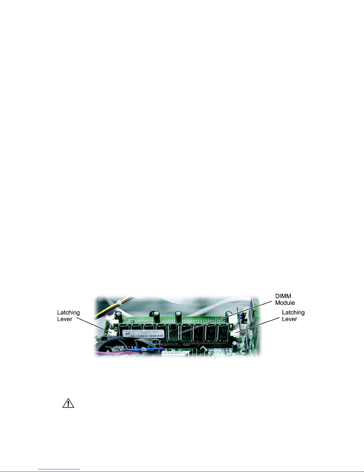
5 Using both hands, carefully set the DIMM module into the center of the left and right latching
levers.
Figure 23. Placing the DIMM Module into the Latching Levers
6 Center the module over the socket. Note that the DIMM modules are keyed in such a way that
they cannot be inserted incorrectly.
Caution
...........................................
Do not force the module in or damage may result. If the DIMM does not go in smoothly, the key may
...........................................
not be lined up.
7 Do not lock the module into position at this time.
Page 74

INSTALLING AND REMOVING HARDWARE
Installing and Removing Memory
10-74
10
8 Be sure the module is centered and the connector pins are aligned. Use both hands to apply
equal pressure on each end of the module and press down to lock the module into the socket.
When the module is locked in place, be sure both latching levers are fully seated into the latching
notches on the sides of the DIMMs. The module should now be standing upright in the socket.
Caution
...........................................
...........................................
Failure to observe proper insertion guidelines may result in damage to the DIMM and/or the socket.
Removing DIMM Modules
To remove DIMM modules, use your thumbs and gently pry the latching levers open so they no
longer hold the module in the socket. Gently lift the module out of the socket.
Page 75
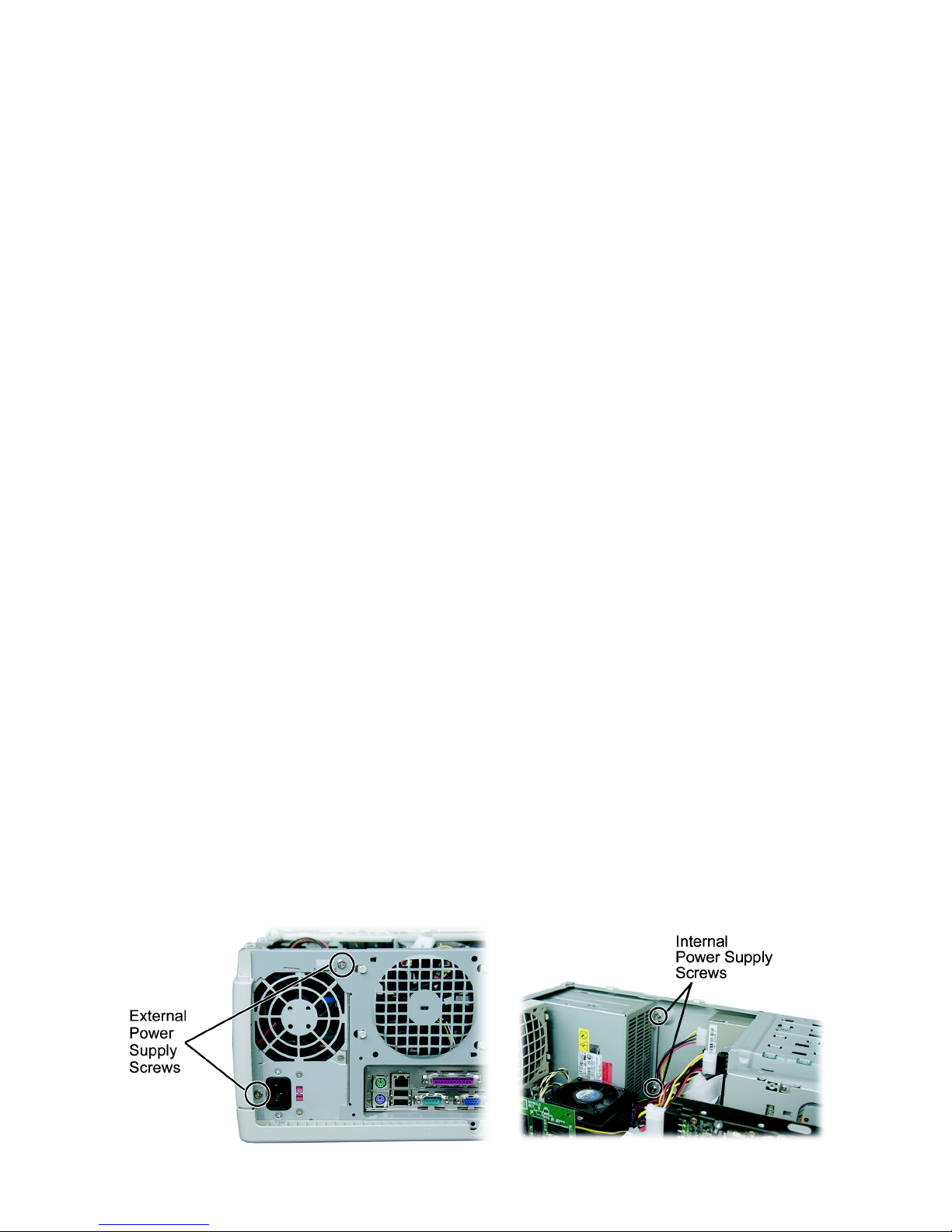
INSTALLING AND REMOVING HARDWARE
Removing and Installing the Power Supply
10-75
.....
...................................................................
REMOVING AND INSTALLING THE POWER SUPPLY
1 Unplug the power cord from the power supply, or the computer could accidentally start.
2 Remove the access panel. See “Removing the Access Panel” on page 9 -53.
3 Unplug all power supply connectors from the motherboard and peripherals. Remove the
motherboard power connector by releasing the plastic latch that locks the connector to the
motherboard.
4 Remove the four Phillips screws that hold the power supply in place. There are two on the
outside of the case and two on the inside (Figure 24).
Figure 24. Removing Power Supply Screws
Page 76

INSTALLING AND REMOVING HARDWARE
Removing and Installing the Power Supply
10-76
10
5 Remove the power supply from the chassis.
6 Insert the replacement power supply into the chassis and attach it using the four Phillips screws
removed earlier.
7 Reconnect all power supply connectors to the motherboard and peripherals.
8 Replace the access panel. See “Replacing the Access Panel” on page 9 -54.
Page 77

11 -77
.....
...................................
S
YSTEMBOARD
11
.................................................................
FEATURES
Your MicronPC computer features a high-performance system board designed to be the basis
for your XP+ computer.
Processor Information
•
Supports AMD®Athlon™ XP processors featuring Quantispeed™ Architecture
•
128-Kbyte (L1) cache, 256-Kbyte on-chip L2 cache
Page 78

SYSTEM BOARD
Features
11 -78
11
Main Memory
•
Supports memory slots for three 184-pin DDR DIMM
•
Support a maximum memory size of 3 GB
Expansion Slots
•
One AGP slot
•
Five 32-bit PCI bus slots
•
One CNR (Communications/Networking Riser) slot
•
Supports 5 V PCI bus interface
On-Board Peripherals
•
One floppy port supports 1 FDD with 360 KB, 720 KB, 1.2 MB, 1.44 MB, and 2.88 MB
densities
•
One parallel port supports SPP/EPP/ECP mode
•
4 USB ports (two rear connector and two front pin header — 4 ports)
•
One Ethernet/LAN adapter jack, one VGA port, and one serial port (COM A)
•
One PS/2 mouse port and one PS/2 keyboard port
On-Board Sound
•
nVidia nForce APU (Audio Processing Unit capable of Dolby 5.1 decoding)
Page 79
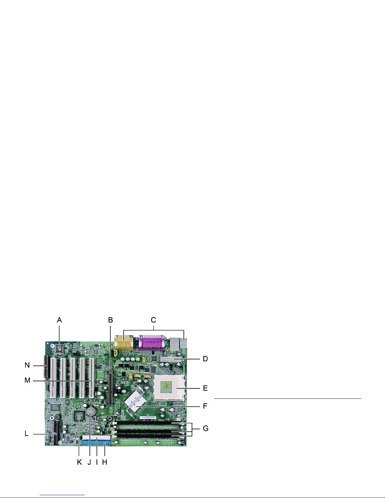
SYSTEM BOARD
System Board Features
11 -79
.....
...................................................................
SYSTEM BOARD FEATURES
Use the following illustration and key to identify the components on your system board.
Figure 25. System Board Layout
Table 9: System Board Component Description
A BIOS H Primary IDE Connector
B AGP Connector I Secondary IDE Connector
C I/O Connectors J Battery
D Power Connector K nForce MCP
E Processor Socket L Floppy Connector
F nForce IGP M PCI Card Connectors
G DIMM Sockets N CNR Audio Connector
Page 80
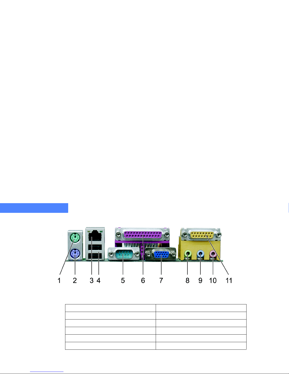
SYSTEM BOARD
System Board Features
11 -80
11
Input/Output Connector Ports
Figure 26. I/O Connector Ports
Tab le 10: I/O Connector Ports Descriptions
1. PS/2 mouse (green) 7. Video port (blue)
2. Keyboard (purple) 8. Line out connector (lime)
3. Ethernet/LAN adapter (black) 9. Line in connector (light blue)
4. 2 USB ports (black) 10. Microphone connector (pink)
5. Com 1 port (teal) 11. MIDI/Game port (gold)
6. Parallel (printer) connector (burgundy)
Page 81

SYSTEM BOARD
CMOS Real Time Clock (RTC)
11 -81
.....
...................................................................
CMOS REAL TIME CLOCK (RTC)
The RTC circuit provides the date and time for the system. If the external battery for the RTC is
low, it will prevent your system from POSTing, and you will not get a display. Normally the life
span of the battery is several years. When necessary, replace the battery with a new 3V lithium
battery (type CR2032).
Flash EEPROM
Your system board uses flash memory to store BIOS firmware. It can be updated as new
versions of the BIOS become available. You can upgrade your BIOS using the flash utility.
...................................................................
REMOVING AND INSTALLING THE SYSTEM BOARD
Removing the System Board
1 Unplug the power cord, or the computer could accidentally start.
2 Remove the access panel. See “Removing the Bezel” on page 9-55.
3 Disconnect all back panel I/O connections (such as a keyboard, printer, or speaker).
4 Disconnect the power supply, fan, and LED connectors from the motherboard. Removing the
power supply connectors requires releasing the plastic latch that locks the connectors to the
system board.
5 Remove all cards. See “Removing a PCI or AGP Card” on page 10 -61.
Page 82
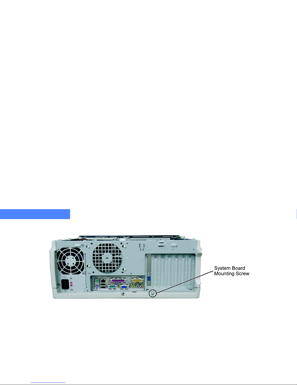
SYSTEM BOARD
Removing and Installing the System Board
11 -82
11
6 Loosen the system board mounting screw (Figure 27).
Figure 27. System Board Mounting Screw
7 Lift the system board up to release it from the hooks, and then slide the system board to the right.
Page 83
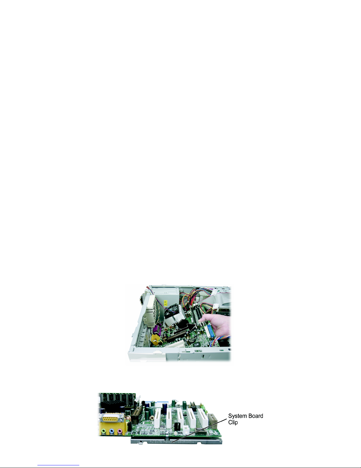
SYSTEM BOARD
Removing and Installing the System Board
11 -83
.....
8 Remove the system board from the case.
Figure 28. Removing the System Board
9 Remove the system board clip, and set the clip aside for use on the replacement system board.
Figure 29. System Board Clip
Page 84

SYSTEM BOARD
Removing and Installing the System Board
11 -84
11
Installing the System Board
1 After completing the steps in the section “Removing the System Board” on page 11-81, attach
the system board clip to the replacement board.
2 Slide the replacement system board into the case.
3 Align the system board holes with the case hooks.
4 Use the system board mounting screw (Figure 27) to securely fasten the system board to the
chassis.
5 Insert all cards. See “Installing a PCI or AGP Card” on page 10-64.
6 Reconnect all data, audio, LED, power supply, power switch, and fan connectors.
7 Replace the access panel. See “Replacing the Access Panel” on page 9 -54.
Page 85

12-85
.....
...................................
BIOS S
ETUPPROGRAM
12
The basic input/output system (BIOS) setup program provides functions that you can use to
modify and configure the integrated devices (modem and audio) as well as the many
subsystems of the PC (hard disk, time and date, power management, and so on).
The configuration information defined through this program allows for upgradability and ease
of configuration. The system contains a battery-supported complementary metal oxide
semiconductor (CMOS) memory location that stores the settings that are made in the setup
program. The attached battery constantly provides the CMOS with power, even when the
computer has been turned off, so these settings are not lost.
The BIOS also controls the startup sequence of the computer and provides the system with
the basic information it needs to initialize to the point where the operating system (Windows)
can boot the PC. The operating system also relies on some of the information provided in
CMOS to ensure proper communication between the software and hardware and also
configures the CPU. If the CMOS information is incorrect, the system may not operate
correctly until accurate information is stored in the CMOS.
Page 86

BIOS SETUP PROGRAM
Running the Setup Program
12-86
12
...................................................................
RUNNING THE SETUP PROGRAM
Although your MicronPC computer arrives fully configured, you may want to customize it to fit
your needs. However, if the information in CMOS is lost, the system will not operate properly
unless the BIOS Setup Program is used to restore the system configuration.
In order for the computer to run properly, run the BIOS Setup Program after first installing a new
system board and whenever you make a hardware change to the computer.
The BIOS Setup Program initially displays the Main menu screen. Each menu screen has
options for modifying different aspects of the system configuration.
Page 87

BIOS SETUP PROGRAM
Changing the BIOS Settings
12-87
.....
...................................................................
CHANGING THE BIOS SETTINGS
If you are unsure of changes you make while in the BIOS screens, you can exit without saving
those changes.
If your system runs poorly or not at all due to the changes you’ve made, you can restore the
default factory settings at the setup prompt and start over. This will not save the operating system
if the hard disk crashes, but if incorrect changes have been made to the BIOS, you can return to
the factory default settings to start over.
Note
...........................................
The figures and tables in this chapter describe and explain your system’s BIOS. In the tables, the default
...........................................
options are formatted in bold.
Note
...........................................
...........................................
Certain BIOS settings vary between Microsoft Windows operating systems.
Page 88

BIOS SETUP PROGRAM
CMOS Setup Utility Menu
12-88
12
...................................................................
CMOS SETUP UTILITY MENU
To access the BIOS Setup Program, press the [Delete] key when instructed during POST. The
CMOS Setup Utility menu will appear.
Figure 30. CMOS Setup Utility
Advanced
CMOS Setup Utility — Copyright (C) 1984–2001 Award Software
Esc : Quit : Select Item
F10 : Save & Exit Setup
Standard CMOS Features
Advanced BIOS Features
Advanced Chipset Features
Integrated Peripherals
Power Managment Setup
PnP/PCI Configuration
PC Health Status
Load Fail-Safe Defau lts
Load Optimized Defaults
Set Supervisor Password
Set User Password
Save & Exit Setup
Exit Without Saving
Page 89

BIOS SETUP PROGRAM
CMOS Setup Utility Menu
12-89
.....
Tab le 11 : CMOS Setup Utility Menu Descriptions
............
Menu Name
......................................
Function
Standard CMOS Features
Opens the menu for the original PC AT-compatible BIOS.
Advanced BIOS Features
Opens the menu for the Award-enhanced BIOS.
Advanced Chipset Features
Opens the menu for the computer’s chipset.
Integrated Peripherals
Opens the menu for the Integrated Peripherals options for the Input/Output systems that depend
on the integrated peripherals controller in the computer.
Power Management Setup
Opens the menu for the system power management.
PnP/PCI Configuration
Opens the menu for the plug-and-play standard and PCI Local Bus configuration.
PC Health Status
Opens the PC Health Status menu which monitors and displays various motherboard parameters,
such as temperatures, voltages, and fan speeds.
Load Fail-Safe Defaults
Loads fail-safe defaults.
Load Optimized Defaults
Loads optimized defaults, which are factory settings for standard system operation.
Set Supervisor Password
Sets the supervisor password required at system boot or required to enter BIOS setup.
Set User Password
Sets the user password required at system boot or to enter BIOS setup.
Save and Exit Setup
Saves changes made to the BIOS. Use this function when you are certain that the changes you
wish to make to the BIOS are correct. The computer will boot to the modified BIOS.
Exit Without Saving
Exits without saving changes made to the BIOS.
Page 90
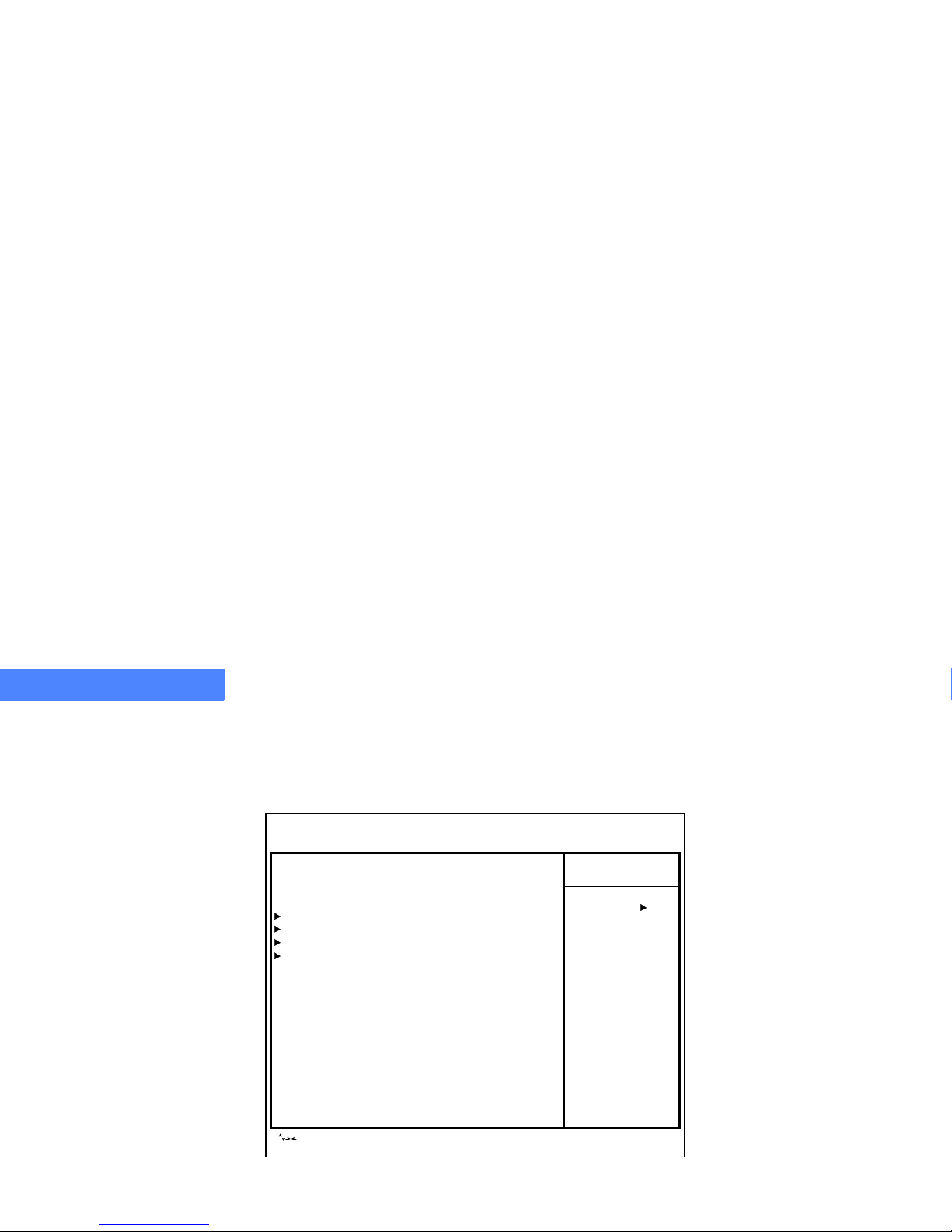
BIOS SETUP PROGRAM
Standard CMOS Features Menu
12-90
12
...................................................................
STANDARDCMOSFEATURESMENU
In the Standard CMOS Features menu, you can set the clock and calendar, record disk drive
parameters, and set video subsystem types.
Figure 31. Standard CMOS Features Menu
Advanced
CMOS Setup Utility — Copyright (C) 1984–2001 Award Software
Standard CMOS Features
Item Help
Menu Level
: Move Enter: Select +/-/PU/PD: Valu e F10: Save Esc: Exit F1: General Help
F5: Previous Values F6:Fail-Safe Defaults F7: Optimized Defaults
Date (mm:dd:yyyy) Wed, Oct 17, 200 1
Time (hh:mm:ss) 13 : 13 : 44
IDE Primary Master <auto-dete cted>
IDE Primary Slave <auto-dete cted>
IDE Secondary Master <auto-detected>
IDE Secondary Slave <auto-detected>
Drive A [1.44, 3.5 in.]
Video [EGA/VGA]
Halt On [All, But Keyboard]
Base Memory Size <auto-detected>
Extended Memory Size <auto-detected>
Total Memory Size <auto-detected>
Page 91

BIOS SETUP PROGRAM
Standard CMOS Features Menu
12-91
.....
Table 12: Standard CMOS Features Menu Descriptions
..........
Menu Name
........................................
Function
Date
To change the date, press the left or right arrow key to move the cursor to the desired field (date,
month, year). Press the [PgUp] or [PgDn] key for a setting or type the desired value into the field.
Time
The time format is based on a 24-hour clock (e.g., 1:30 PM = 13:30:00). To change the Time, use the
left or right arrow key to move to the desired field. Press the [PgUp] or [PgDn] key for a setting or type
the desired value into the field.
IDE Primary Master
Auto-detects the primary master hard disk drive.
IDE Primary Slave
Auto-detects the primary slave hard disk drive.
IDE Secondary Master
Auto-detects the secondary master hard disk drive.
IDE Secondary Slave
Auto-detects the secondary slave hard disk drive.
Drive A
Selects the correct specification for the floppy disk drive installed in the computer.
Video
Selects the type of primary video subsystem in your computer. This should remain set to EGA/VGA
for all modern video cards.
Halt On
During the POST, the computer stops if the BIOS detects a hardware error. You can tell the BIOS to
ignore certain errors during POST and continue the Boot-Up process. The options are: No errors; All
errors; All, But Keyboard; All, But Diskette; and All, But Disk/Key. The default is All, But Keyboard.
Base Memory Size
Auto-detects the base memory size.
Extended Memory Size
Auto-detects the extended memory size.
Total Me mory Size
Auto-detects the total memory size.
Page 92
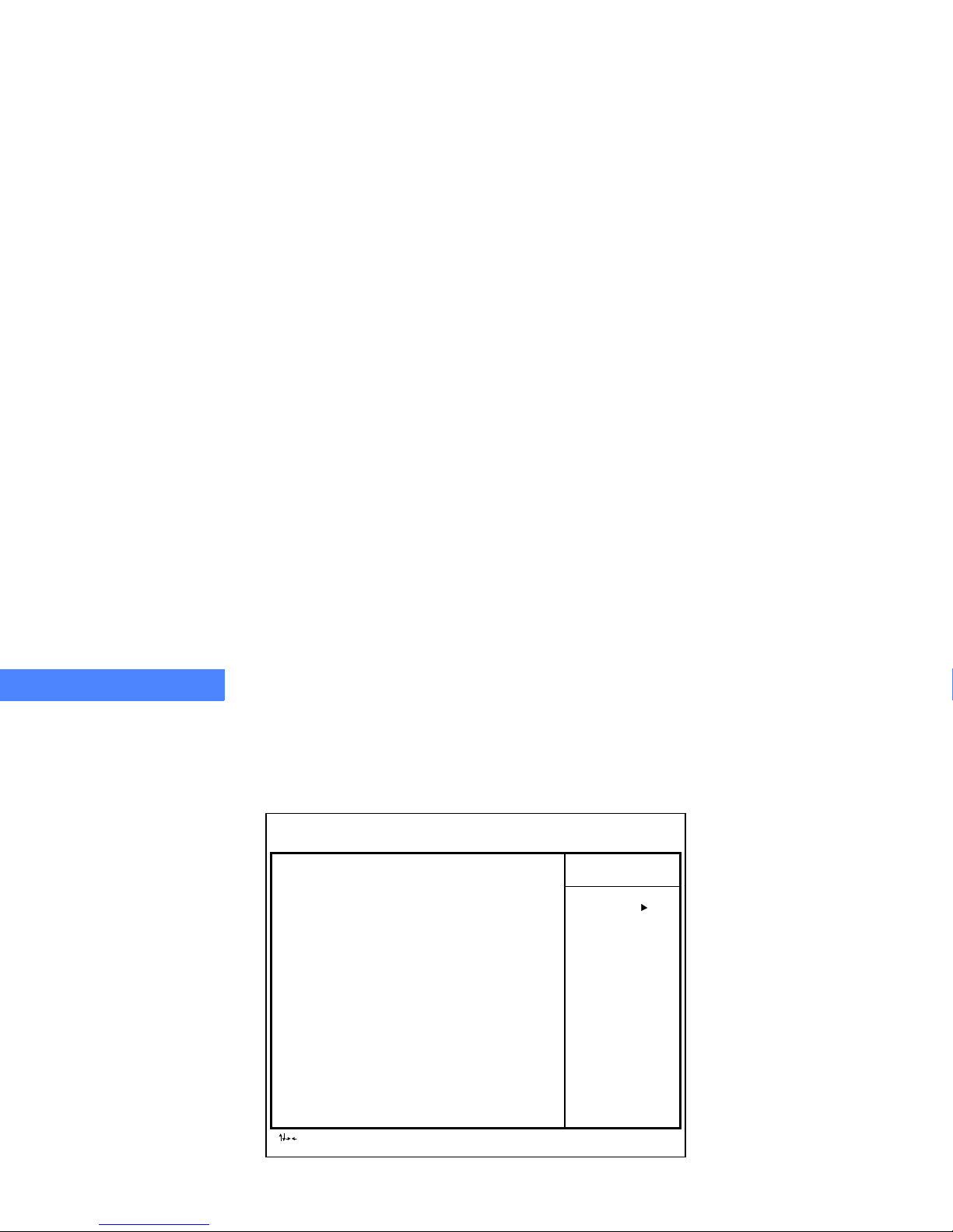
BIOS SETUP PROGRAM
Advanced BIOS Features Menu
12-92
12
...................................................................
ADVANCEDBIOSFEATURESMENU
The Advanced BIOS Features menu contains industry-standard options for changing some of
the more basic operations of the BIOS.
Figure 32. Advanced BIOS Features Menu
Advanced
CMOS Setup Utility — Copyright (C) 1984–2001 Award Software
Advanced BIOS Features
Item Help
Menu Level
: Move Enter: Select +/-/PU/PD: Valu e F10: Save Esc: Exit F1: General Help
F5: Previous Values F6:Fail-Safe Defaults F7: Optimized Defaults
CPU Internal Cac he [Enabled]
External Cache [Enabled]
Quick Power On Self Test [Enabled]
FirstBootDevice [CDROM]
Second Boot Device [Floppy]
Third Boot Device [HDD-0]
Boot Up Numlock Status [On]
Security Option [Setup]
Page 93

BIOS SETUP PROGRAM
Advanced BIOS Features Menu
12-93
.....
Table 13: Advanced BIOS Features Menu Descriptions
............
.
Menu Name
......................................
Function
CPU Internal Cache
Use this function to enable or disable the CPU internal cache. The default is Enabled.
External Cache
Use this function to enable or disable the computer’s external cache. The default is Enabled.
Quick Power on Self Test
Use this function to allow the system to skip certain tests while booting. This function will
decrease the time needed to boot the system. The default is Enabled.
First Boot Device
Use this function to specify the boot sequence. The BIOS allows eleven different boot sequence
options using three drives in a user-specified order. In addition to the traditional A and C Drives,
options include IDE hard disk drives D, E, and F, a SCSI hard disk drive, and a CD-ROM drive.
Default is CD-ROM.
Second Boot Device
Use this function to specify the second boot device in the boot sequence. The default is Floppy.
Third Boot Device
Use this function to specify the third boot device in the boot sequence. The default is HDD-0.
Boot Up Numlock Status
Use this function to determine whether the NumLock key will be on or off when the system
boots. The default is On.
Security Option
Use this function to select whether a password is required every time the system boots or only
when you enter setup. The default is Setup.
Page 94
BIOS SETUP PROGRAM
Advanced Chipset Features Menu
12-94
12
...................................................................
ADVANCED CHIPSET FEATURES MENU
The Advanced Chipset Features menu contains options for changing video- and memoryrelated operations in the BIOS.
Figure 33. Advanced Chipset Features Menu
Advanced
CMOS Setup Utility — Copyright (C) 1984–2001 Award Software
Advanced Chipset Features
Item Help
Menu Level
: Move Enter: Select +/-/PU/PD: Valu e F10: Save Esc: Exit F1: General Help
F5: Previous Values F6:Fail-Safe Defaults F7: Optimized Defaults
AGP Aperture Si ze [64MB]
Frame Buffer Size [32M]
Page 95

BIOS SETUP PROGRAM
Advanced Chipset Features Menu
12-95
.....
Table 14: Advanced Chipset Features Menu Descriptions
.........
.
Menu Name
........................................
.
Function
AGP Aperture Size
Use this function to specify the aperture size for the AGP video controller. The aperture is a portion of
the PCI memory address dedicated to graphics memory address space. The default is 64MB.
Frame Buffer Size
Use this function to specify the amount of system memory to be used as dedicated to the frame buffer
for systems using the integrated graphics features of the motherboard.
Please note: Your total system memory will be decremented by the frame buffer amount. IE: Systems
with 256MB RAM and a 32MB frame buffer setting will report 224MB of physical system memory. This
setting has no effect on systems using an add-in AGP graphics adapter. The default is 32M.
Page 96
BIOS SETUP PROGRAM
Integrated Peripherals Menu
12-96
12
...................................................................
INTEGRATED PERIPHERALS MENU
The Integrated Peripherals menu contains options for changing how the system’s integrated
devices are managed by the BIOS.
Figure 34. Integrated Peripherals Menu
Advanced
CMOS Setup Utility — Copyright (C) 1984–2001 Award Software
Integrated Peripherals
Item Help
Menu Level
: Move Enter: Select +/-/PU/PD: Valu e F10: Save Esc: Exit F1: General Help
F5: Previous Values F6:Fail-Safe Defaults F7: Optimized Defaults
MCP OnChip IDE Device [Press Enter]
MCP OnChip PCI Device [Press Enter]
Onboard Super IO Dev ice [Press Enter]
Init Display First [Onboard/AGP]
OnChip USB [Enabled]
USB Keyboard Support [Enabled]
IDE HDD Block Mode [Enabled]
Page 97

BIOS SETUP PROGRAM
Integrated Peripherals Menu
12-97
.....
Table 15: Integrated Peripherals Menu Descriptions
...........
Menu Name
.......................................
Function
MCP OnChip IDE Device
Pressing [Enter] brings up the MCP OnChip IDE Device submenu.
MCP OnChip PCI Device
Pressing [Enter] brings up the MCP OnChip PCI Device submenu.
Onboard Super IO Device
Pressing [Enter] brings up the Onboard Super IO Device submenu.
Init Display First
Use this function to chose between PCI and onboard/AGP video options. The default is
Onboard/AGP.
OnChip USB
Use this function to enable or disable the onboard USB controller. The default is Enabled.
USB Keyboard Support
Use this function to enable or disable support for a USB keyboard. The default is Enabled.
IDE HDD Block Mode
Enabling this function allows the hard disk controller to use fast block mode to transfer information
to and from your hard disk drive. The default is Enabled.
Page 98
BIOS SETUP PROGRAM
MCP OnChip IDE Device Submenu
12-98
12
...................................................................
MCP ONCHIP IDE DEVICE SUBMENU
The MCP OnChip IDE Device submenu contains options for changing how resources, such as
the OnChip IDE channel and the master/slave PIO and UDMA, will be managed by the BIOS.
Figure 35. MCP OnChip IDE Device Submenu
Advanced
CMOS Setup Utility — Copyright (C) 1984–2001 Award Software
MCP OnChip IDE Device
Item Help
Menu Level
: Move Enter: Select +/-/PU/PD: Valu e F10: Save Esc: Exit F1: General Help
F5: Previous Values F6:Fail-Safe Defaults F7: Optimized Defaults
OnChip IDE Chanel0[Enabled]
OnChip IDE Channel1 [Enabled]
Page 99

BIOS SETUP PROGRAM
MCP OnChip IDE Device Submenu
12-99
.....
Tab le 16: MCP OnChip IDE Submenu Descriptions
............
Menu Name
......................................
Function
OnChip IDE Channel0
Use this function to enable or disable the primary controller. You might choose to disable the
controller if you were to add a high performance or specialized controller. The default is Enabled.
OnChip IDE Channel1
Use this function to enable or disable the secondary controller. You might choose to disable the
controller if you were to add a high performance or specialized controller. The default is Enabled.
Page 100
BIOS SETUP PROGRAM
MCP OnChip PCI Device Submenu
12-100
12
...................................................................
MCP ONCHIP PCI DEVICE SUBMENU
The MCP OnChip PCI Device submenu contains options for changing how resources, such as
MCP audio, modem, and LAN, will be managed by the BIOS.
Figure 36. MCP OnChip PCI Device Submenu
Advanced
CMOS Setup Utility — Copyright (C) 1984–2001 Award Software
MCP OnChip PCI Device
Item Help
Menu Level
: Move Enter: Select +/-/PU/PD: Valu e F10: Save Esc: Exit F1: General Help
F5: Previous Values F6:Fail-Safe Defaults F7: Optimized Defaults
MCP AC97 Audio [Enabled]
MCP OnChip LAN [Enabled]
MCP SPDIF Out [Enabled]
 Loading...