


S e r i e s
Reference Manual
Precision Linear / Stepper Motor Stage
(Open and Closed Loop Versions)
PPS-20

PPS-20
Linear/Stepper Motor
Positioner Stage
Reference Manual
Rev 3.03
MICRONIX USA, LLC
15375 Barranca Parkway, E-106
Irvine, CA 92618
Tel: 949-480-0538
Fax: 949-480-0538
Email: info@micronixusa.com
http://micronixusa.com

PPS-20 LMSM Precision Stepper Stage
1
Rev: 3.03
MICRONIX USA,LLC
Irvine, California
www.micronixsusa.com
Reference Manual
Contents
1. Introduction 3
1.1 Product Description 3
1.2 Stepper Motor – (SM-002) 3
1.3 Linear Motor – (LM-003) 3
1.4 Recommended Controllers 4
1.5 Technical Data 4
1.6 Load Characteristics 4
2. Model Configurations 5
2.1 PPS-20 SM Order Numbers 5
2.2 PPS-20 LM Order Numbers 6
3. Preparing to Install the PPS-20 LMSM Stage 7
3.1 Installation Preparation 7
3.2 Package Contents 7
4. Installing the PPS-20 LMSM Stage 8
4.1 PPS-20 LMSM Installation 8
4.1.1 General Mounting 8
4.1.2 X-Y Mounting 9
5. Connecting the PPS-20 LMSM Stage 10
5.1 Atmospheric Environments 10
5.1.1 Open Loop Installation & Wiring Diagram 10
5.1.2 Closed Loop/Encoder Installation & Wiring Diagram 11
5.2 Vacuum Environments 13
5.2.1 Handling and Preparation 13
5.2.2 Open loop Installation & Wiring Diagram 13
5.2.3 Closed Loop/Encoder Installation & Wiring Diagram 14
6. Technical Specifications 15
6.1 Dimensions 15
6.1.1 PPS-20 Stepper Motor Analog Encoder 15
6.1.2 PPS-20 Stepper Motor MII 6000 Digital Encoder 16
6.1.3 PPS-20 Linear Motor Analog Encoder 17
6.1.4 PPS-20 Linear Motor MII 6000 Digital Encoder 18
7. Stacking Configurations 19
7.1 Configuration Examples 19
8. Supplementary Information 20
8.1 Maintenance 20

PPS-20 LMSM Precision Stepper Stage
2
Rev: 3.03
MICRONIX USA,LLC
Irvine, California
www.micronixsusa.com
Reference Manual
8.2 Units And Conventions 20
8.3 Accessories 20
A. Appendix 21
A.1 Stepper Motor 21
A.1.1 Standard Atmospheric DB-9 Male Motor Connector 21
A.1.2 Stepper Motor Specifications 21
A.2 Linear Voice-Coil Motor 22
A.2.1 Standard Atmospheric DB-9 Male Motor Connector 22
A.2.2 Linear Motor Specifications 22
A.3 Magnetic (Hall Effect) Limit Switches 24
Power Pin 8 24
A.4 Open Loop Vacuum Wiring Diagram 25
A.4.1 Straight Through 9-Pin Feed Through 25
A.5 Using an Analog Encoder 26
A.5.1 Analog Encoder Overview 26
A.5.2 Encoder Pin-Out 26
A.5.3 Operating and Electrical Specifications 26
A.5.4 Analog Output (Pins 1,2,6 and 7) 26
A.5.5 Index Window (Pins 3) 26
A.5.6 Resolution 27
A.5.7 Analog Encoder Wiring Diagram 27
A.6 Using the Digital Encoder Module 28
A.6.1 Encoder Module Pin-out 28
A.6.2 Operating and Electrical Specifications 29
A.6.3 Output Signals & Signal Termination for A quad B, Index and limits 29
A.6.4 Resolution 29
A.6.5 MII 6000 Digital Encoder Wiring Diagram 30
A.6.6 Straight Through 25-Pin Feed Through 30

PPS-20 LMSM Precision Stepper Stage
3
Rev: 3.03
MICRONIX USA,LLC
Irvine, California
www.micronixsusa.com
Reference Manual
1. Introduction
1.1 Product Description
The PPS-20 is a low profile, high-precision linear stage outfitted with a linear or
stepper motor. Miniature cross-roller bearings assure high stiffness and guiding
accuracy for loads up to 20N (horizontal orientation). The PPS-20 LMSM is
available in travel lengths of up to 51mm, and an optional linear encoder
provides submicron repeatability. High Vacuum (10-6 mbar) compatible versions
are available.
Features:
§ Stepper Motor travel ranges of 12mm, 18mm, 26mm, and 51mm
§ Linear Motor travel ranges of 11mm, 18mm, and 25mm
§ Load capacity up to 20N
§ Optional 2nm resolution external digital encoder or 10nm Analog encoder
1.2 Stepper Motor – (SM-002)
1.3 Linear Motor – (LM-003)
PPS-20 20mm Open Loop
(Shown in center position)
PPS-20 20mm Closed Loop
with analog encoder
(Shown in center position)
PPS-20 20mm Closed Loop
with digital encoder
(Shown in center position)
PPS-20 20mm Closed Loop
with 10nm analog encoder
(Shown in center position)
PPS-20 20mm Closed Loop
with 2nm digital encoder
(Shown in center position)

PPS-20 LMSM Precision Stepper Stage
4
Rev: 3.03
MICRONIX USA,LLC
Irvine, California
www.micronixsusa.com
Reference Manual
1.4 Recommended Controllers
The following controllers are available from MICRONIX USA:
§ MMC-200 [Stepper Motor Versions]
§ MMC-300 [Linear Motor Versions]
1.5 Technical Data
1.6 Load Characteristics
Load Characteristics
Fx(N)
Fy(N)
Fz(N)
Mx(Nm)
My(Nm)
Mz(Nm)
SM-002
10
20
20
0.7
0.7
0.7
LM-003
1
20
20
0.7
0.7
0.7
Motor option
SM-002
LM-003
Speed, max. [mm/sec]
4
100
Encoder option
Open Loop
Analog
(1 Vpp)
Digital
(RS-422)
Analog
(1 Vpp)
Digital
(RS-422)
Resolution, typical [μm]
0.1
0.1
0.1
0.01
0.002
Repeatability,
bi-directional [µm]
± 4 ± 0.2
± 0.2
± 0.05
± 0.02
Repeatability,
uni-directional [µm]
0.5 0.2 0.2 0.05
0.02
Accuracy [µm]
± 10
± 1
± 1
± 1
± 1

PPS-20 LMSM Precision Stepper Stage
5
Rev: 3.03
MICRONIX USA,LLC
Irvine, California
www.micronixsusa.com
Reference Manual
2. Model Configurations
2.1 PPS-20 SM Order Numbers
Ý
Only available with option 3 digital encoder selection.
Contact MICRONIX USA for custom applications and stacking configurations.
Order No. PPS-20
2
Stepper Motor SM-002 2
12mm Travel 1
18mm Travel 2
26mm Travel 3
51mm Travel 5
Open Loop 0
Analog (1Vpp) 2
Digital (RS-422) 3
No Limit Switch 0
Magnetic 1
Optical* 2
Non-vacuum 0
Vacuum prepared, 10-6 mbar 6

PPS-20 LMSM Precision Stepper Stage
6
Rev: 3.03
MICRONIX USA,LLC
Irvine, California
www.micronixsusa.com
Reference Manual
2.2 PPS-20 LM Order Numbers
Ý
Only available with option 3 digital encoder selection.
Contact MICRONIX USA for custom applications and stacking configurations.
Order No. PPS-20
3
Linear Motor LM-003 3
11mm Travel 1
18mm Travel 2
25mm Travel 3
Analog (1V
pp
), 10nm 2
Digital (RS-422), 2nm 3
No Limit Switch 0
Magnetic 1
Optical* 2
Non-vacuum 0

PPS-20 LMSM Precision Stepper Stage
7
Rev: 3.03
MICRONIX USA,LLC
Irvine, California
www.micronixsusa.com
Reference Manual
3. Preparing to Install the PPS-20 LMSM Stage
3.1 Installation Preparation
When mounting the stage it is important to consider the flatness of the mounting
surface, as the stage will conform to the shape of that surface. A surface that is
not flat can adversely affect the performance and structural integrity of the
stage.
The stage is calibrated and guaranteed to be within specification at 20°C ±5°C,
unless otherwise specified. Be sure to use the stage under the following
conditions:
§ Mount to a clean and flat surface which is free of debris, burrs or dings
§ An indoor atmosphere free of corrosive gases, excessive dust, and
condensation
§ Temperature range of 0-40°C
§ Relative humidity between 20-80%
§ Locate away from water, heat, and electrical noise
3.2 Package Contents
If product is damaged or there are missing components, contact MICRONIX USA
immediately. Do not discard product packaging in case of return shipment.
Package Should Contain:
§ PPS-20 Linear Stage
§ Reference Manual
§ Any other previously agreed upon components such as a controller
PPS-20 LMSM Precision Stepper Stage
8
Rev: 3.03
MICRONIX USA,LLC
Irvine, California
www.micronixsusa.com
Reference Manual
4. Installing the PPS-20 LMSM Stage
Mounting patterns require M2 screws for mounting and M1.5 x 5mm dowel pins
for precision alignment. Additional brackets and screws may be required for
custom applications.
4.1 PPS-20 LMSM Installation
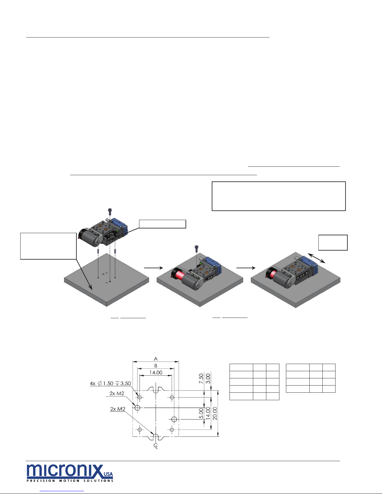
4.1.1 General Mounting
For general mounting configurations, mount the base to the mounting surface
using the thru holes. Move the carriage to access base mounting pattern.
(Please note, it is possible to move the carriage of the linear motor configurations
manually without damaging the stage, however, for *stepper versions the motor
must be driven by a controller to reposition the carriage.)
Stepper Motor
Linear Motor
Travel
A B
Travel
A
B
12mm
20
16 11mm
20
16
18mm
30
16 18mm
30
16
26mm
40
36 25mm
40
36
51mm
80
50
Requires:
2x M1.5 x 5mm Dowel Pins
2x M2 Socket Head Cap Screws
1. Move carriage via controller*, if
necessary, to access mounting
hole. Insert Pins and M2 SHCS as
shown.
Direction
of Travel
Clearance Hole
Customer Supplied
Base Plate or
Mounting Surface
2. Move carriage via controller*, if
necessary, to access remaining
mounting hole. Install M2 SHCS as
shown.

PPS-20 LMSM Precision Stepper Stage
9
Rev: 3.03
MICRONIX USA,LLC
Irvine, California
www.micronixsusa.com
Reference Manual
4.1.2 X-Y Mounting
For X-Y mounting, follow the instructions for mounting the X-axis stage, outlined in
section 4.1.1 General Mounting, then proceed to mount the Y-axis stage, as
shown below (Please note, it is possible to move the carriage of the linear motor
configurations manually without damaging the stage, however, for *stepper
versions the motor must be driven by a controller to reposition the carriage.):
Requires:
2x M1.5 x 5mm Dowel Pins
4x M2 Socket Head Cap Screws
(For stacking screws, use M2 x 5mm SHCS)
Direction
of Travel
1. Move Y-Axis Stage carriage via
controller
*, if necessary, to access
mounting hole. Install M2
SHCS as
shown.
2. Move carriage via controller*, if
necessary, to access remaining
mounting hole. Install M2 SHCS as
shown.
Y-Axis Stage
PPS-20 LMSM Precision Stepper Stage
10
Rev: 3.03
MICRONIX USA,LLC
Irvine, California
www.micronixsusa.com
Reference Manual
5. Connecting the PPS-20 LMSM Stage
5.1 Atmospheric Environments
For controller information refer to the appropriate MMC controller manual.
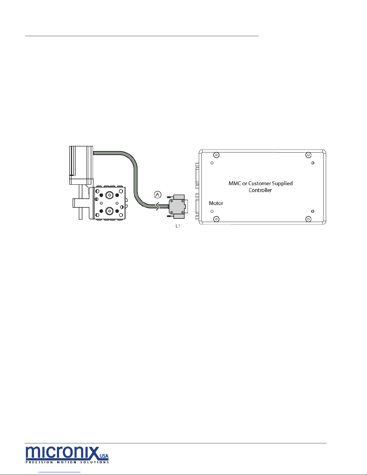
5.1.1 Open Loop Installation & Wiring Diagram
Connecting the PPS-20 LMSM stage in an open loop configuration only requires
that the D-sub 9 Pin male Motor Cable be connected to a compatible controller.
No other cables or components are required. Note: Open loop configurations
are not available for linear motor versions.
Stepper Motor Version

PPS-20 LMSM Precision Stepper Stage
11
Rev: 3.03
MICRONIX USA,LLC
Irvine, California
www.micronixsusa.com
Reference Manual
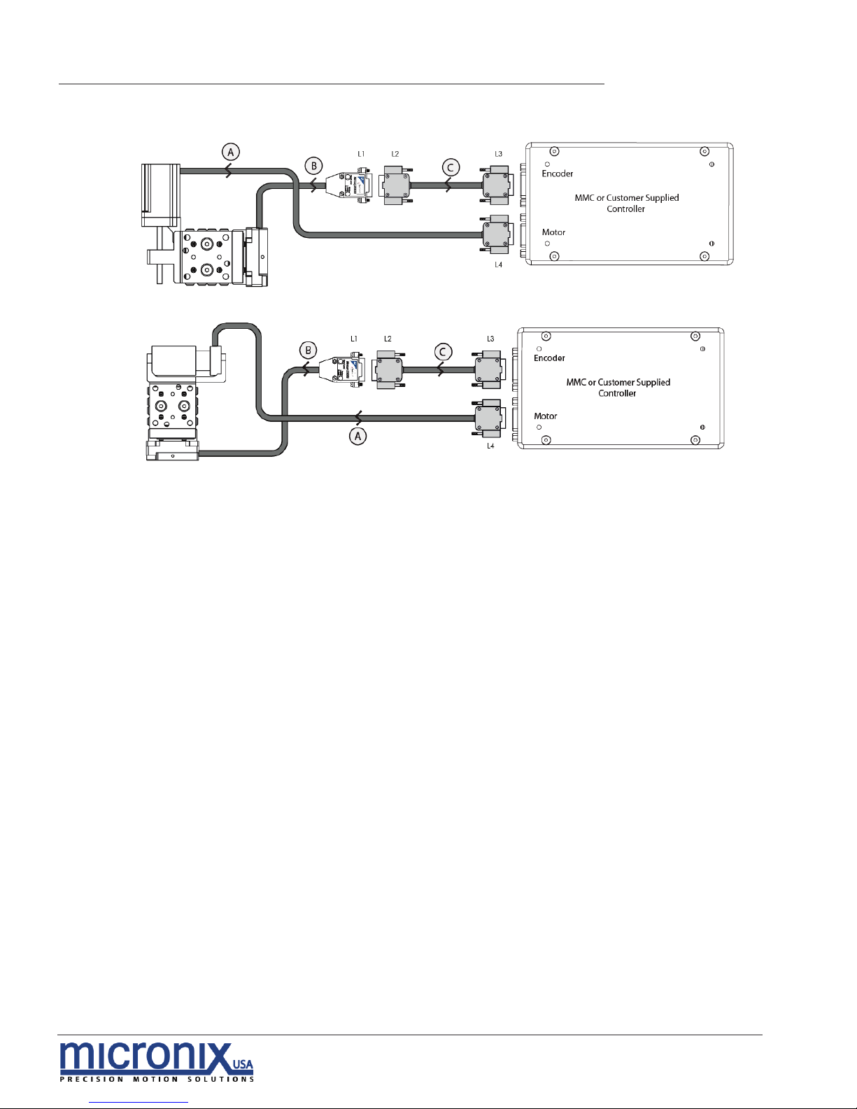
5.1.2 Closed Loop/Encoder Installation & Wiring Diagram
Using the PPS-20 LMSM stage with an encoder requires a closed loop compatible
controller that recognizes encoder feedback. Connect the stage as shown
below.
5.1.2.1 Analog Encoder Wiring Diagram
Stepper Motor Version
Linear Motor Version
PPS-20 LMSM Precision Stepper Stage
12
Rev: 3.03
MICRONIX USA,LLC
Irvine, California
www.micronixsusa.com
Reference Manual
5.1.2.2 MII 6000 Digital Encoder Wiring Diagram
Stepper Motor Version
Linear Motor Version

PPS-20 LMSM Precision Stepper Stage
13
Rev: 3.03
MICRONIX USA,LLC
Irvine, California
www.micronixsusa.com
Reference Manual
5.2 Vacuum Environments
5.2.1 Handling and Preparation
When preparing the stage for vacuum environments, take the necessary
precautions (such as wearing gloves, clean room, clothing, etc.) when handling
the stage as to avoid any contaminants. Maximum Bake-out temperature is
100°C. MICRONIX USA can supply the stage with vacuum compatible
connectors: 9-pin female PEEK connector for open loop, 15-Pin female PEEK
connector for closed loop with analog encoder, 25-pin female PEEK connector
for closed loop with MII 6000 digital encoder.
5.2.2 Open loop Installation & Wiring Diagram
Connecting an open loop PPS-20 LMSM stage in a vacuum chamber requires
the use of a feed through connector at the vacuum chamber wall. The vacuum
compatible PPS-20 LMSM will be supplied with wiring for a straight through feed
through, not a cross over gender changer. MICRONIX USA supplies test
connectors that simulate the vacuum feed through to allow for functionality
testing prior to installation in a vacuum chamber. For details regarding the pinout and feed through specifications see the Appendix A.4. Note: Linear motor
versions are not available for vacuum environments.
Stepper Motor Version
Temporary test
connectors are
standard. Requires
customer supplied
feed through
connector

PPS-20 LMSM Precision Stepper Stage
14
Rev: 3.03
MICRONIX USA,LLC
Irvine, California
www.micronixsusa.com
Reference Manual
5.2.3 Closed Loop/Encoder Installation & Wiring Diagram
Closed loop installation of the PPS-20 LMSM stage in vacuum environments
requires an intermediate feed through connector at the vacuum chamber wall
that can accommodate both the motor cable, and the encoder cable.
The vacuum compatible PPS-20 LMSM stage will be supplied with wiring for a
straight through feed through, not a cross over gender bender. MICRONIX USA
supplies test connectors that simulate the vacuum feed through to allow for
functionality testing prior to installation in a vacuum chamber. For details
regarding the pin-out and feed through specifications see the Appendix A.5.7,
A.6
.5.
5.2.3.1 Analog Encoder Wiring Diagram
5.2.3.2 MII 6000 Digital Encoder Wiring Diagram
Stepper Motor Version
Stepper Motor Version
Temporary test
connectors are
standard. Requires
customer supplied
feed through
connector
Temporary test
connectors are
standard. Requires
customer supplied
feed through
connector

PPS-20 LMSM Precision Stepper Stage
15
Rev: 3.03
MICRONIX USA,LLC
Irvine, California
www.micronixsusa.com
Reference Manual
6. Technical Specifications
6.1 Dimensions
6.1.1 PPS-20 Stepper Motor Analog Encoder
L
TRAVEL
A B C D E
F
20
12
6 1 2
15
16
47.7
30
18
6 1 2
25
16
57.7
40
26
10 3 6
35
36
57.7
80
51
18 7 14
75
50
87.7
* Grey parts for external closed loop
only

PPS-20 LMSM Precision Stepper Stage
16
Rev: 3.03
MICRONIX USA,LLC
Irvine, California
www.micronixsusa.com
Reference Manual
6.1.2 PPS-20 Stepper Motor MII 6000 Digital Encoder
L
TRAVEL
A B C D E
F
20
12
6 1 2
15
16
47.7
30
18
6 1 2
25
16
57.7
40
26
10 3 6
35
36
57.7
80
51
18 7 14
75
50
87.7
* Grey parts for external closed loop
only

PPS-20 LMSM Precision Stepper Stage
17
Rev: 3.03
MICRONIX USA,LLC
Irvine, California
www.micronixsusa.com
Reference Manual
6.1.3 PPS-20 Linear Motor Analog Encoder
L
TRAVEL
A B C D E
F
20
11
6 1 2
15
16
40
30
18
6 1 2
25
16
54.5
40
25
10 3 6
35
36
66.8
* Grey parts for external closed loop
only

PPS-20 LMSM Precision Stepper Stage
18
Rev: 3.03
MICRONIX USA,LLC
Irvine, California
www.micronixsusa.com
Reference Manual
6.1.4 PPS-20 Linear Motor MII 6000 Digital Encoder
L
TRAVEL
A B C D E
F
20
11
6 1 2
15
16
40
30
18
6 1 2
25
16
54.5
40
25
10 3 6
35
36
66.8
* Grey parts for external closed loop
only

PPS-20 LMSM Precision Stepper Stage
19
Rev: 3.03
MICRONIX USA,LLC
Irvine, California
www.micronixsusa.com
Reference Manual
7. Stacking Configurations
7.1 Configuration Examples (Additional Configurations available upon request)
Ø Additional configurations available upon request
Ø Note: Stacking compatibility for all motor configurations.
Ø Positioning according to:
No Adapters
X-Y 11x11mm
X-Y 11x25mm
X-Y 18x18mm
X-Y 51x18mm
X-Y 26x11mm
[with PPS-28 Linear Stage]
Using Adapter Plate (P/N: 430509)
X-Y-Z 51x18x12mm
[3 PPS-20 SM Stages]
X-Y-Z 12x12x12mm
[3 PPS-20 SM Stages]
PPS-20 LMSM Precision Stepper Stage
20
Rev: 3.03
MICRONIX USA,LLC
Irvine, California
www.micronixsusa.com
Reference Manual
8. Supplementary Information
8.1 Maintenance
§ The PPS-20 LMSM stage is a precision mechanical device
and should be handled with care. Do not drop or mishandle
the stage.
§ Do not touch the bearings, as this will contaminate the lubrication and
jeopardize the longevity of the stage.
§ Follow the Installation Preparation requirements and use proper cable
management to ensure a clean and safe operating environment.
§ Allow for easy access to the stage in case of servicing.
8.2 Units And Conventions
All measurements in this document are in the metric system of units.
Metric Unit
English Unit
1 millimeter
0.0394 inches
1 micron
0.0000394 inches
1 Newton
0.2248 lbs
1 Newton-meter
8.85 in-lbs
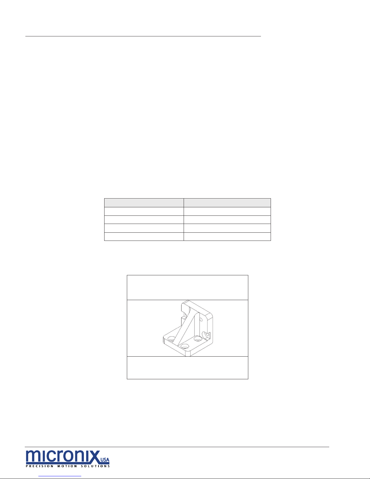
8.3 Accessories
430509
Z-Bracket Adapter Plate
Used to adapt the PPS-20 series to a
perpendicular assembly for XZ
mounting configurations.

PPS-20 LMSM Precision Stepper Stage
21
Rev: 3.03
MICRONIX USA,LLC
Irvine, California
www.micronixsusa.com
Reference Manual
A. Appendix
A.1 Stepper Motor
A.1.1 Standard Atmospheric DB-9 Male Motor Connector
A.1.2 Stepper Motor Specifications
Stepper Motor
Pin
Function
Wire Color
1
Motor A+
Yellow
2
Motor A-
Green
3
Motor B+
Black
4
Motor B-
Red
5
N/A
N/A
6
Limit Switch-
Violet
7
Limit Switch+
Blue
8
+5V
Orange
9
Ground
Brown
w
Solder shield to housing
Stepper Motor
Motor Type
2 Phase Bipolar
Phase Current
0.2 A
Step Angle
18°
Fullsteps per Rev
20
Coil-Resistance
13 Ohms
Coil-Inductance
3.5 mH
Holding Torque
2.4 mHm
Pitch
0.5 mm/rev
Resolution/Fullstep
2.5 μm

PPS-20 LMSM Precision Stepper Stage
22
Rev: 3.03
MICRONIX USA,LLC
Irvine, California
www.micronixsusa.com
Reference Manual
A.2 Linear Voice-Coil Motor
A.2.1 Standard Atmospheric DB-9 Male Motor Connector
A.2.2 Linear Motor Specifications
Linear Motor
Pin
Function
Wire Color
1
Negative (-)
Black
2
Positive (+)
Red
3
N/A
N/A
4
N/A
N/A
5
N/A
N/A
6
Limit Switch+
Violet
7
Limit Switch-
Blue
8
+5V
Orange
9
Ground
Brown
w
Solder shield to housing
Linear Motor - 11mm Version
Intermittent Force @10% Duty Cycle
2.55 N
9.2 oz
Continuous Force
0.81 N
2.9 oz
Force Constant
0.77 N/A
2.8 oz/A
Back EMF Constant
0.77 V/m/s
0.020 V/in/s
Stroke
12.7 mm
0.50 in
Coil Clearance Per Side
0.33 mm
0.013 in
Coil Assy Mass
6.4 gr
0.23 oz
Body Mass
10.6 gr
0.37 oz
Coil Resistance
3.2 Ohms
Coil Inductance @120 Hz
0.5 mH
Max Continuous Power
3.5 W
Linear Motor - 18mm Version
Intermittent Force @10% Duty Cycle
2.51 N
9.0 oz
Continuous Force
0.79 N
2.9 oz
Force Constant
0.80 N/A
2.9 oz/A
Back EMF Constant
0.80 V/m/s
0.020 V/in/s
Stroke
19.1 mm
0.75 in
Coil Clearance Per Side
0.33 mm
0.013 in
Coil Assy Mass
9.0 gr
0.32 oz
Body Mass
13.8 gr
0.49 oz
Coil Resistance
4.6 Ohms
Coil Inductance @120 Hz
0.7 mH
Max Continuous Power
4.5 W

PPS-20 LMSM Precision Stepper Stage
23
Rev: 3.03
MICRONIX USA,LLC
Irvine, California
www.micronixsusa.com
Reference Manual
Linear Motor - 25mm Version
Intermittent Force @10% Duty Cycle
2.20 N
7.9 oz
Continuous Force
0.70 N
2.5 oz
Force Constant
0.76 N/A
2.7 oz/A
Back EMF Constant
0.76 V/m/s
0.019 V/in/s
Stroke
25.4 mm
1.000 in
Coil Clearance Per Side
0.33 mm
0.013 in
Coil Assy Mass
10.8 gr
0.38 oz
Body Mass
17 gr
0.60 oz
Coil Resistance
5.9 Ohms
Coil Inductance @120 Hz
1.0 mH
Max Continuous Power
5.0 W

PPS-20 LMSM Precision Stepper Stage
24
Rev: 3.03
MICRONIX USA,LLC
Irvine, California
www.micronixsusa.com
Reference Manual
A.3 Magnetic (Hall Effect) Limit Switches
Hall Effect transistor switches are activated in the presence of a magnetic field.
These switches feature a highly repeatable operation, remote sensing noncontacting operation, broad temperature range (-40 to +150°C), and
exceptionally long life.
The hall effect limit switches are factory calibrated to ensure advertised travel
length, and cannot be adjusted by the customer.
A.3.1 Hall Effect Limit Switches
Supply Voltage
3 - 12 VDC
Supply Current
˂ 5 mA
Output Configuration
Open Collector
Max Sink Current
20 mA
Contact Rating
100 mA @ 30 V
Contact Type
Open Collector (NPN)
Normally Closed
Operating Temperature
-40 to +150 °C
A.3.2 Limit Switch Schematic
Power Pin 8
Limit Switch
Common (Pin 9)
- Limit Switch (Pin 7)
+ Limit Switch (Pin 6)

PPS-20 LMSM Precision Stepper Stage
25
Rev: 3.03
MICRONIX USA,LLC
Irvine, California
www.micronixsusa.com
Reference Manual
A.4 Open Loop Vacuum Wiring Diagram
Standard Cable Descriptions:
A. PPS-20 Motor Cable - Vacuum Side (Female Dsub 9 Pin Peek Connector, 1.5m)
B. Atmospheric Motor Cable (Female Dsub 9 Pin to Male Dsub 9 Pin, 1.5m)
Wiring Diagram:
A.4.1 Straight Through 9-Pin Feed Through
Stepper Motor Connector Pinout
Description
Color
L1
L2
L3
L4
L5
Motor Phase A+
Yellow
5 5 1
1 (White - Green TP)
1
Motor Phase A-
Green 4 4 2 2 (Green)
2
Motor Phase B+
Black 3 3
3
3 (White - Brown TP)
3
Motor Phase B-
Red 2 2 4 4 (Brown)
4
Limit Switch -
Violet 9 9 6 6 (Violet)
6
Limit Switch +
Blue 8 8 7 7 (White - Violet TP)
7
+5V
Orange
7 7 8
8 (Red)
8
Limit Ground
Brown 6 6 9 9 (Black)
9
Shield - 1 1 5
5 (Shield)
Casing
-Motor
Stepper Version

PPS-20 LMSM Precision Stepper Stage
26
Rev: 3.03
MICRONIX USA,LLC
Irvine, California
www.micronixsusa.com
Reference Manual
A.5 Using an Analog Encoder
A.5.1 Analog Encoder Overview
A PPS-20 LMSM stage with Analog encoder will need to be paired with an appropriate
controller. MMC controllers has an Analog option. The PPS-20 LMSM stage with internal
Analog encoder will be supplied with a 15 pin connector that incorporates both motor
and encoder signals.
A.5.2 Encoder Pin-Out
A.5.3 Operating and Electrical Specifications
A.5.4 Analog Output (Pins 1,2,6 and 7)
A.5.5 Index Window (Pins 3)
Pin
Color
Description
1
Brown
Cos+
2
Yellow
Sin+
3
Violet
Index +
4
Black
Ground
5
Red
+5V
6
Orange
Cos-
7
Green
Sin-
8
Blue
Index -
9
Not in Use
Not In Use
Power Supply
5VDC ±5% @ 330mA (60mA for sensor)
Operating Temperature
0 to 70°C
Humidity
10 - 90% RH non-condensing

PPS-20 LMSM Precision Stepper Stage
27
Rev: 3.03
MICRONIX USA,LLC
Irvine, California
www.micronixsusa.com
Reference Manual
A.5.6 Resolution
.
All closed loop stages are supplied with 20µm scales. The interpolation is done
in an MMC controller to a higher resolution as specified in the order. With an
analog encoder the MMC controller has an achievable resolution of 10nm.
A.5.7 Analog Encoder Wiring Diagram
Standard Cable Descriptions:
A. PPS-20 Motor Cable - Vacuum Side
B. PPS-20 Encoder Cable - Vacuum Side
C. Atmospheric Motor Breakout Cable (Female Dsub 25 Pin to Male Dsub 9 Pin, 1.5m)
D. Atmospheric Encoder Breakout Cable (Female Dsub 25 Pin to Female Dsub 9 Pin, 0.5m)
Wiring Diagram:
Stepper Motor Connector Pinout
Description
Color
L1
L2
L3
L4
L5
L6
Motor B-
Red 1 1
13
13 (Brown)
4
Ground
Brown
14
14
25
25 (Black)
9
Motor B+
Black 2 2
12
12 (White - Brown TP)
3
+5V
Orange
15
15
24
24 (Red)
8
Motor A-
Green 3 3
11
11 (Green)
2
Limit +
Blue
16
16
23
23 (White - Violet TP)
7
Motor A+
Yellow
4 4 10
10 (White - Green TP)
1
Limit -
Violet
17
17
22
22 (Violet)
6
Shield - 5 5 9
9 (Shield)
Casing
Enc Shield
- 8 8 6 6 (Shield)
Casing
+5V
Red
10
10 4 4 (Red)
5
Ground
Black
22
22
17
17 (Black)
4
Cos+
Brown
11
11 3 3 (Brown)
1
Cos-
Orange
23
23
16
16 (White - Brown TP)
6
Sin+
Yellow
12
12 2 2 (Yellow)
2
Sin-
Green
24
24
15
15 (White - Yellow TP)
7
Index+
Violet
13
13 1 1 (Violet)
3
Index-
Blue
25
25
14
14 (White - Violet TP)
8
-Encoder
-Motor
(Female Dsub 25 Pin Peek Connector - 1.5m each)
Stepper Version

PPS-20 LMSM Precision Stepper Stage
28
Rev: 3.03
MICRONIX USA,LLC
Irvine, California
www.micronixsusa.com
Reference Manual
A.6 Using the Digital Encoder
Module
When using the digital external encoder
configuration, the Encoder Module
should display two green LED’s
indicating a power source and proper
encoder alignment. A Red or Yellow
Signal Level LED indicates misalignment
of the Encoder Head, if this occurs
contact MICRONIX USA. Do not adjust
the Encoder Head or scale. For more
information refer to MicroE Systems
Mercury Encoders.
A.6.1 Encoder Module Pin-out
*-Limits must be specified at the time of order, and
calibrated at the factory.
Note: Tri-state alarm: A and B are tri-stated if the encoder
signal becomes too low for reliable operation.
Pin
Description
Pin
Description
1
*Right Limit+
9
Ground
2
Ground
10
*Left Limit+
3
*Right Limit-
11
*Left Limit-
4
Index-
12
Index+
5
B-
13
B+
6
A-
14
A+
7
+5V
15
(not used)
8
+5V

PPS-20 LMSM Precision Stepper Stage
29
Rev: 3.03
MICRONIX USA,LLC
Irvine, California
www.micronixsusa.com
Reference Manual
A.6.2 Operating and Electrical Specifications
A.6.3 Output Signals & Signal Termination for A quad B, Index and limits
*Output signals are differential. Inverse signals are not shown for clarity.
**Note: At some interpolations values the index pulse may be aligned with other states of A or B
than the ones shown.
***Above are with reference to the sensor’s optical centerline
A.6.4 Resolution
All closed loop stages are supplied with 20µm scales. The digital encoder
module interpolates to a higher resolution as specified in the order. With a
digital encoder an MMC controller has an achievable resolution of 2nm.
Power Supply
5VDC ±5% @ 140mA (No outputs terminated)
@ 180mA (A, B, I, and both limits
terminated); 50mA at the sensor
Operating Temperature
0 to 70°C
Humidity
10 - 90% RH non-condensing

PPS-20 LMSM Precision Stepper Stage
30
Rev: 3.03
MICRONIX USA,LLC
Irvine, California
www.micronixsusa.com
Reference Manual
A.6.5 MII 6000 Digital Encoder Wiring Diagram
Standard Cable Descriptions:
A. PPS-20 Motor Cable - Vacuum Side
B. PPS-20 Encoder Cable - Vacuum Side
C. Atmospheric Motor Breakout Cable (Female Dsub 25 Pin to Male Dsub 9 Pin, 1.5m)
D. Atmospheric Encoder Module Breakout Cable (Female Dsub 25 Pin to MII 6000 Interpolator Module, 1m)
E. Encoder Module Adapter Cable (Female Dsub 15 to Female Dsub 9 Pin, 0.5m)
Wiring Diagram:
A.6.6 Straight Through 25-Pin Feed Through
Description
Color
L1
L2
L3
L4
L8
Motor B-
Red 1 1
13
13 (Brown)
4
Ground
Brown
14
14
25
25 (Black)
9
Motor B+
Black 2 2
12
12 (White - Brown TP)
3
+5V
Orange
15
15
24
24 (Red)
8
Motor A-
Green 3 3
11
11 (Green)
2
Limit +
Blue
16
16
23
23 (White - Violet TP)
7
Motor A+
Yellow
4 4 10
10 (White - Green TP)
1
Limit -
Violet
17
17
22
22 (Violet)
6
Shield - 5 5 9
9 (Shield)
Casing
+5V DC
Red 8 8 6 6 (Red)
GND
Black
20
20
19
19 (Black)
DCLK-
Gray 9 9 5 5 (Gray)
DCLK+
White - Gray TP
21
21
18
18 (White - Gray TP)
MISO-
Violet
10
10 4 4 (Violet)
MISO+
White - Violet TP
22
22
17
17 (White - Violet TP)
MOSI-
Blue
11
11 3 3 (Blue)
MOSI+
White - Blue TP
23
23
16
16 (White - Blue TP)
nSS-
Green
12
12 2 2 (Green)
nSS+
White - Green TP
24
24
15
15 (White - Green TP)
CLK-
Brown
13
13 1 1 (Brown)
CLK+
White - Brown TP
25
25
14
14 (White - Brown TP)
Shield - 7 7 7
7 (Shield)
-Encoder
-Motor
w
Note: For the pinout of cable E, refer to the appropriate MMC manual.
Stepper Version
(Female Dsub 25 Pin Peek Connector, 1.5m)
 Loading...