

Page 1
Page 2

1 | P a g e
Rev 2.01
Contents
1. Introduction ............................................................................................................................. 2
1.1 Product Description .......................................................................................................... 2
1.2 Features ............................................................................................................................ 2
2. Quick Start .............................................................................................................................. 2
2.1 Inventory .......................................................................................................................... 3
2.2 Quick Start: Connecting Your Motion Device. ................................................................ 4
2.3 Getting Your Target PC Ready ........................................................................................ 6
2.4 Quick Start: Using the Micronix Motion Controller Platform ......................................... 7
2.5 Motion With and Without Encoders .............................................................................. 15
3. Frequently Asked Questions ................................................................................................. 15
4. Trouble Shooting .................................................................................................................. 15
5. Technical Information ........................................................................................................... 17
5.1 MMC-10 Specifications ................................................................................................. 17
5.2 Serial Port Setup ............................................................................................................. 17
5.3 RJ11 RS485 Bus ............................................................................................................ 17
6. Operation............................................................................................................................... 18
6.1 Axis Addressing ............................................................................................................. 18
6.2 Feedback Control ........................................................................................................... 18
6.3 MLN, MLP, and User Defined References .................................................................... 19
7. Commands ............................................................................................................................ 19
7.1 Command Line Syntax ................................................................................................... 19
7.2 Command Line Format .................................................................................................. 20
7.3 Global Commands .......................................................................................................... 20
7.4 Multiple Parameters ....................................................................................................... 20
7.5 Synchronous Move ......................................................................................................... 20
7.6 Internal Programming .................................................................................................... 21
7.7 Terminating Characters .................................................................................................. 21
7.8 Summary of Commands ................................................................................................. 22
7.9 Command Descriptions .................................................................................................. 24
8. Pin Outs ................................................................................................................................. 88
Page 3
2 | P a g e
Rev 2.01
1. Introduction
This document is a quick start guide to be used to get the MMC-10 and accompanying stages
connected and functional.
1.1 Product Description
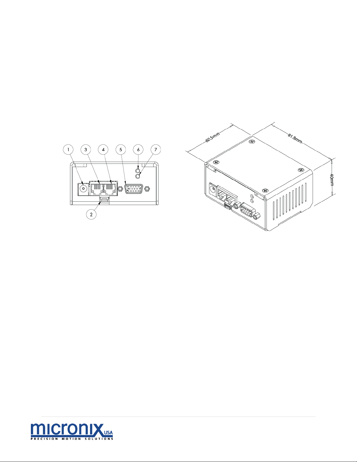
The MMC-10 is a low cost two phase piezo motor controller/driver designed to be
used as a standalone single axis unit or interconnected for multi-axis functionality.
1. 12V to 36V DC in (24V Nominal, peak current draw 0.5A)
2. USB Connector
3. Intermodular/RS-485 Input
4. Intermodular/RS-485 Output
5. Motor/Encoder
6. LED Addressing Indicator 2
a. Orange – Stage is Unaddressed
b. Green – Stage has an address and is ready
7. LED Error Indicator 1
a. Red – An error has occurred
1.2 Features
• Integrated controller/driver for MICRONIX USA stick-slip piezo motors
• Ultra-compact design
• Open loop/closed loop operation
• Closed loop resolution dependent on the encoder
2. Quick Start
Page 4
3 | P a g e
Rev 2.01
2.1 Inventory
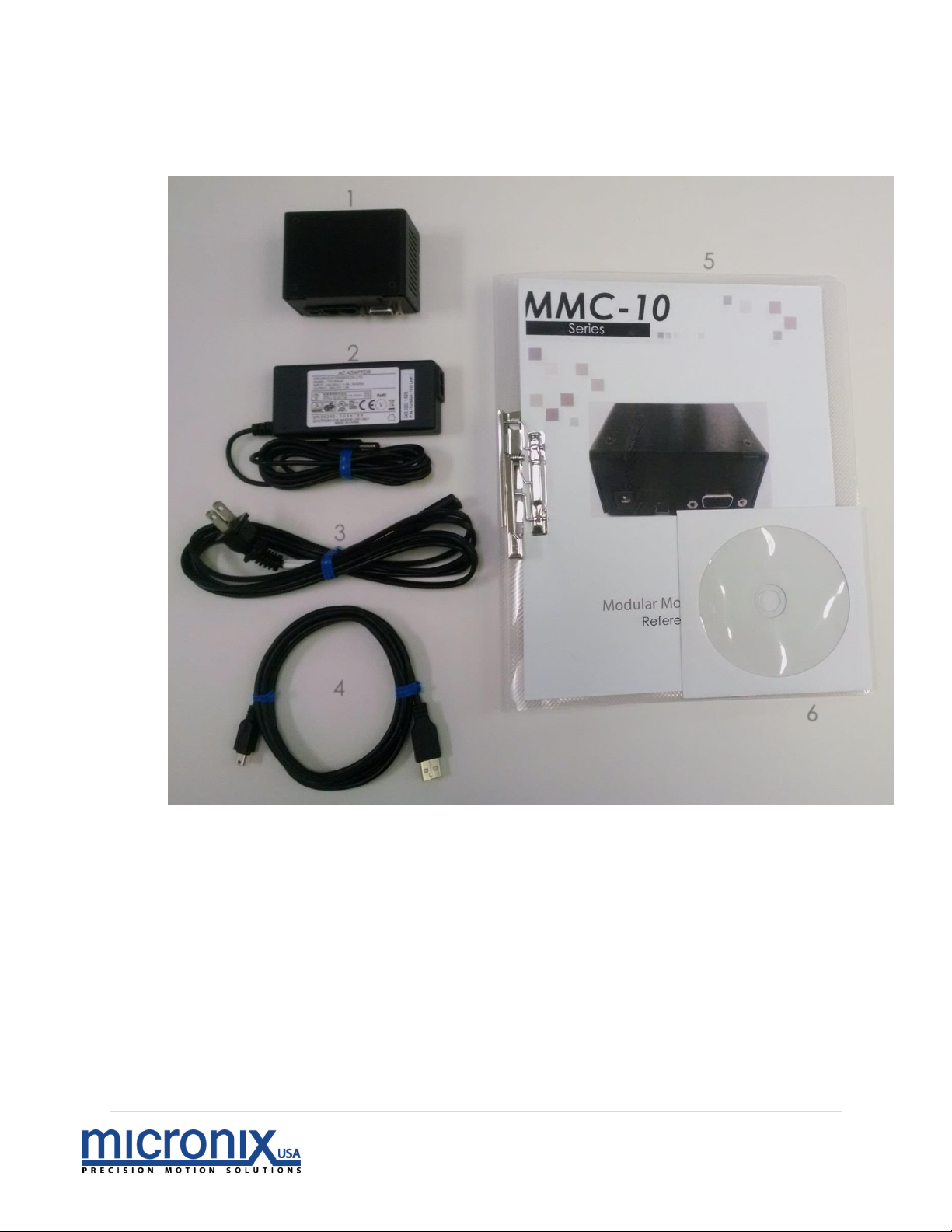
We will begin the setup process by making sure all the components we will need are
accounted for. With every MMC-10 controller, the following should be included:
Package Contents:
1. MMC-10 Controller
2. 24V Power Supply
3. Power Cable
4. 6’ USB Cable
5. User Manual
6. Supplemental CD
7. RJ-11 Daisy Chain Cable (Optional)
1
2
3
4 5 6
Page 5
4 | P a g e
Rev 2.01
2.2 Quick Start: Connecting Your Motion Device.
Now that we have confirmed we have everything we need; we can get the
controller and stages set up.
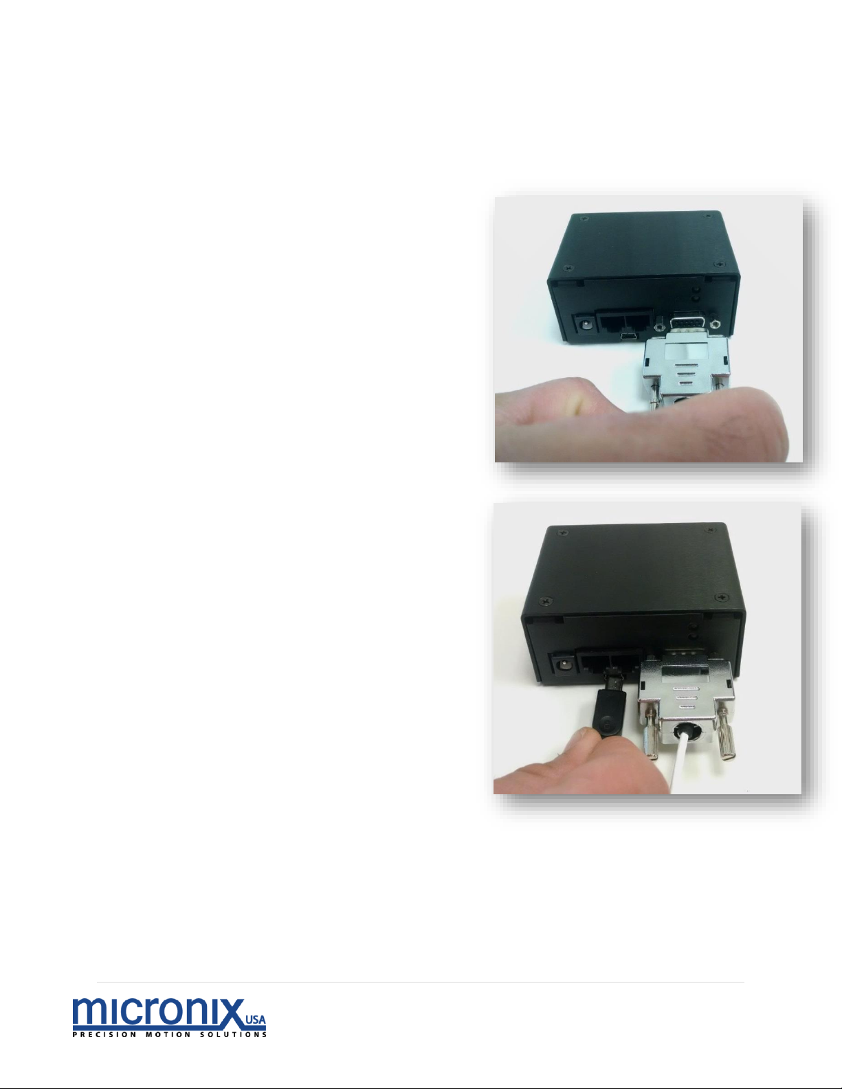
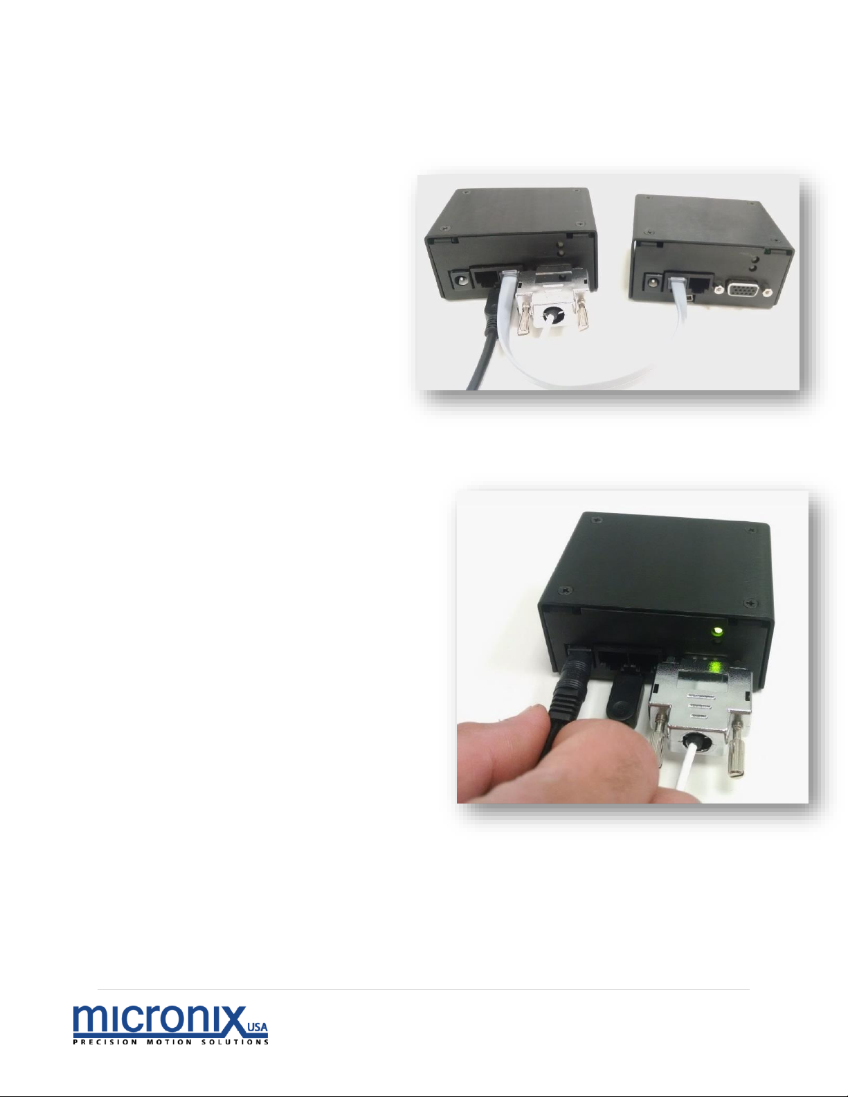
1. Connect MMC-10 to Motion Devices:
Each stage to be used with an MMC-10 will
have a male DSUB15 HD connector
attached to it. Plug this into the
motor/encoder plug on the MMC-10 unit.
This connector will connect the motor to the
drive circuitry of the controller, and on
closed loop stages will additionally serve to
relay the encoder data back to the
controller (Pinout available in manual
appendix).
2. Connect MMC-10 to Computer:
Connect the mini USB connector on the
MMC-10 unit to your pc using the included
6’ USB cable.
Page 6
5 | P a g e
Rev 2.01
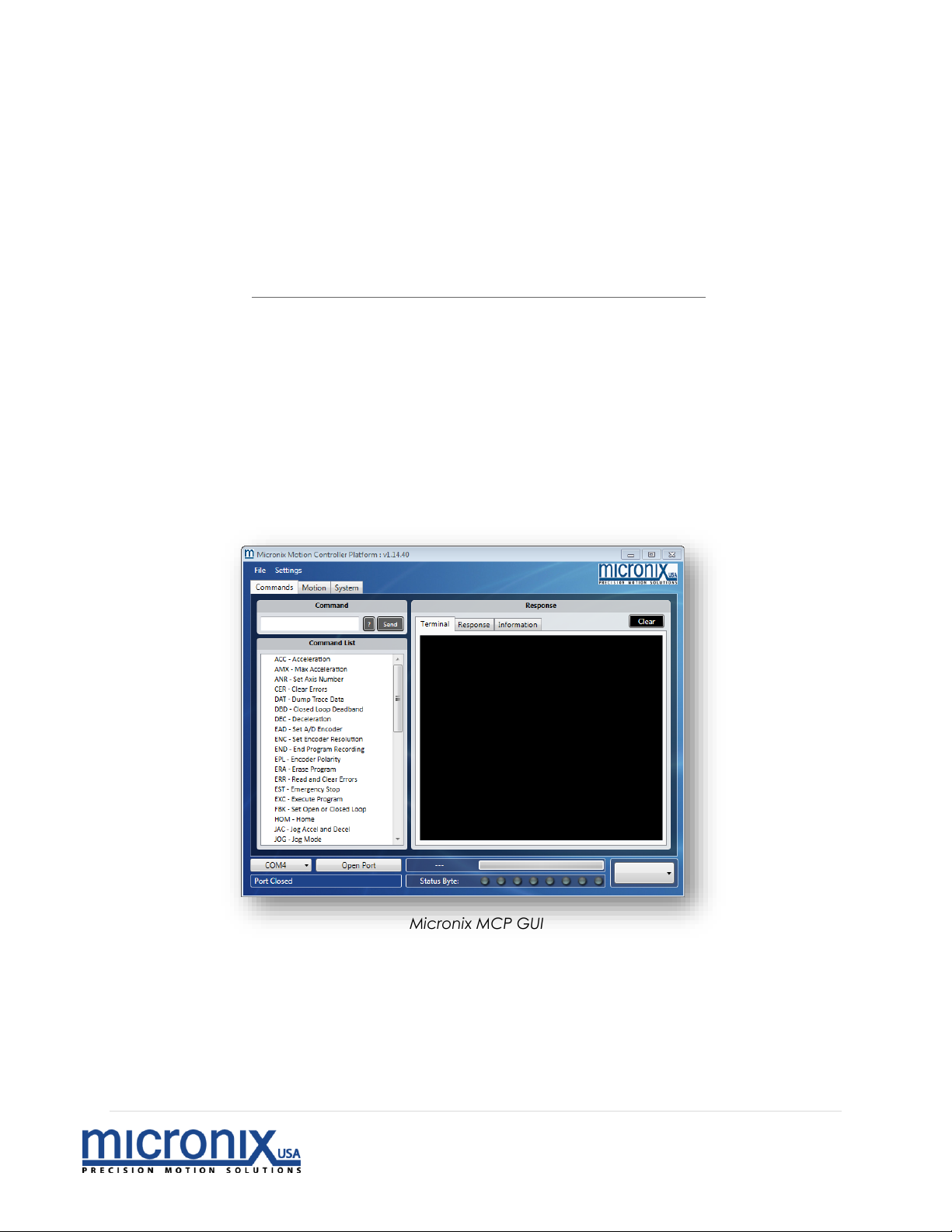
3. (Optional) Connect MMC-10 units together
The MMC-10 has both an in and an out jack for RS-485 communication. This
jack also distributes power and is responsible for addressing in situations where
the auto address function is
used. Connect the output of
one MMC-10 to the input of
another to daisy chain multiple
MMC-10 controllers together,
sharing power and a
communication bus (Pinout
available in manual appendix).
Axes will be addressed in the
order they are connected, a
unit who’s “in” jack is
connected to another units
“out” jack will have an address
one higher than the unit it is
daisy chained to, starting with 1.
4. Connect MMC-10 to Power
Now that everything is connected,
power on the device by plugging in
the 24V power supply. At this point,
the upper LED should be lit green.
Page 7
6 | P a g e
Rev 2.01
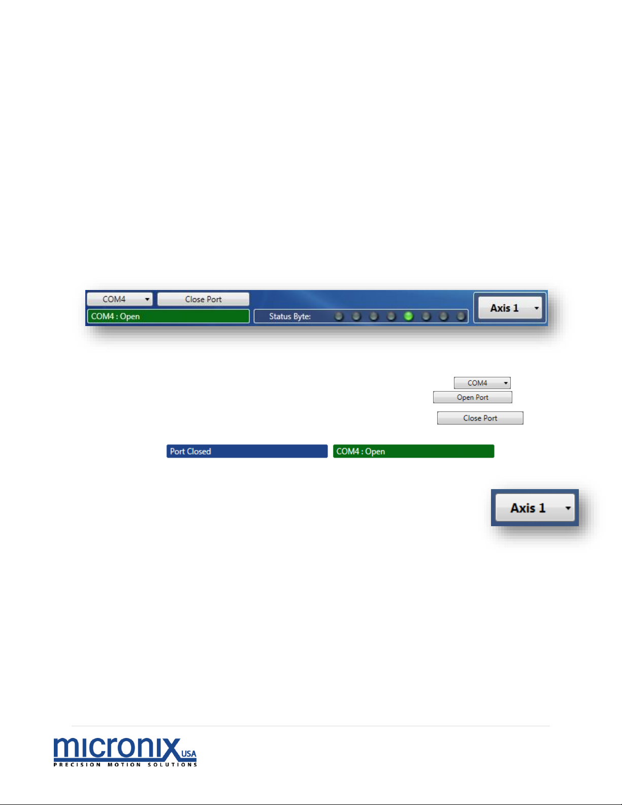
Micronix MCP GUI
2.3 Getting Your Target PC Ready
There are a number of ways to control Micronix controllers, but let’s start by setting
up the Micronix MCP user interface on your PC.
1. Install
a. To install the Micronix motion controller platform double click the
setup.exe file on the supplied CD or downloaded from
http://www.micronixusa.com/motion/support/softwares.cfm and
follow the on screen instructions.
b. If the on-screen instructions do not take you all the way through the
installation process, see the Troubleshooting section on page 15 of this
manual.
2. Run
a. Open the start menu (Windows 7/Vista) or the Start screen (Windows
8/10)
b. Open the ‘all programs’ tab (Windows 7/Vista) or use the down arrow
to navigate to the Apps screen (Windows 8/10)
c. Open the Micronix folder (Windows 7/Vista) or navigate to the Micronix
section of the Apps screen by scrolling sideways (Windows 8/10)
d. Run the Micronix MCP program.
Page 8
7 | P a g e
Rev 2.01
2.4 Quick Start: Using the Micronix Motion Controller Platform
Now that we have connected a stage to a controller, and a controller to a PC, it’s time to
tie it all together. Your PC should automatically recognize the device plugged into it (your
controller) as a com port with the following specs:
By default, Micronix devices will appear as “COM 4”. If this com port is already occupied,
it will appear as the next available com port. If there is uncertainty about which COM port
your Micronix device is occupying, or if you are unable to communicate with your Micronix
device via com port, skip to the troubleshooting section on page 15 of this manual for help
resolving this issue.
With a com port identified, it is time to connect to the MMC-10 using the Micronix MCP
program installed in section 2.2.
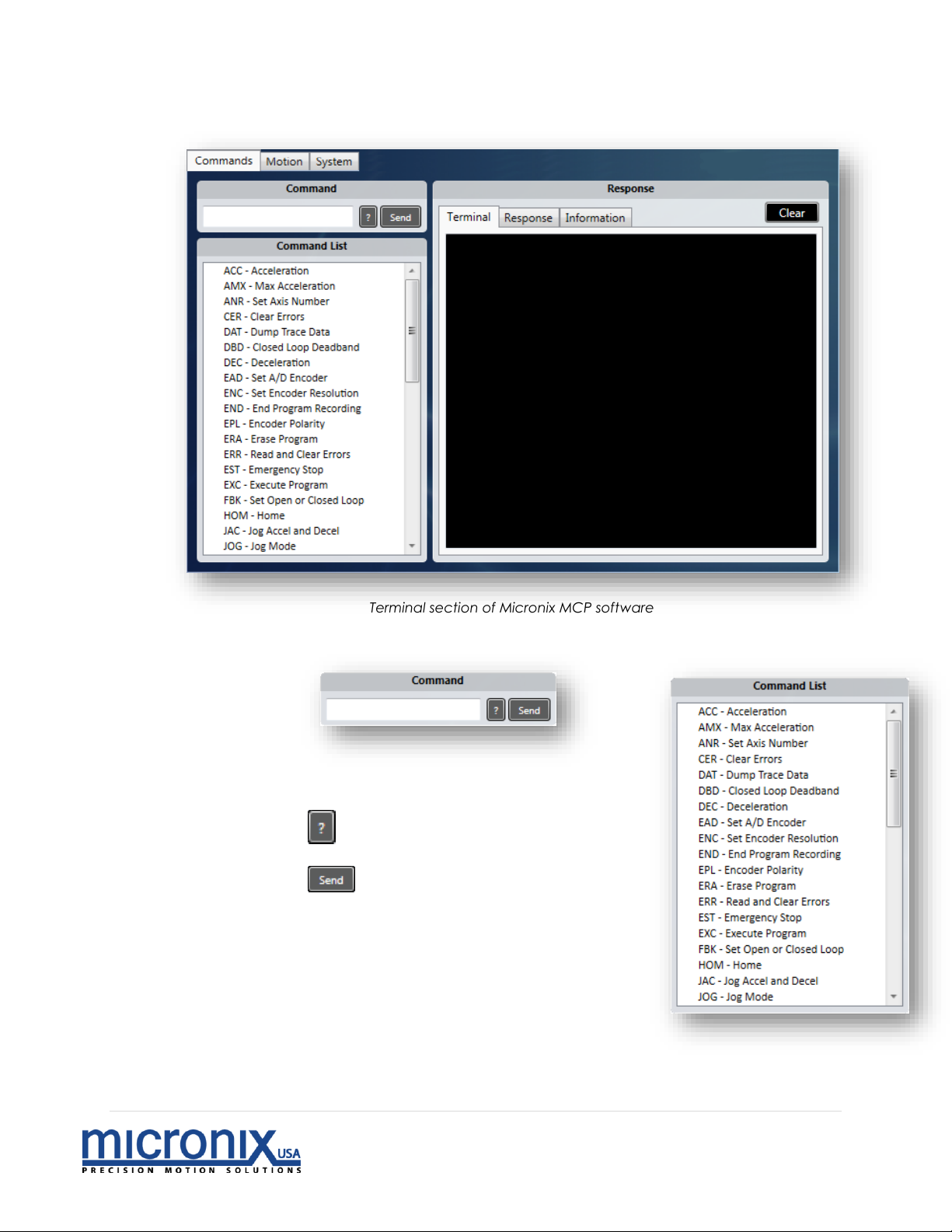
1. Port Control
a. Select the COM port associated with your MMC-10 device
b. Click the Open Port button to connect to the MMC-10
i. This button should change giving you the
option to close the port
c. The Port field should change to indicate the Port is Open.
d. You will see the progress bar fill and the adjacent field change with
information regarding the query process as the program
initializes. You are now ready to start moving a stage with your
MMC-10.
e. The Axis selector will allow you to switch control between
different axes, if multiple axes are being used.
Port Control section of Micronix MCP software
Page 9
8 | P a g e
Rev 2.01
Terminal section of Micronix MCP software
2. Commands
a. Command – This field allows you to interface with your MMC-10 through manual
terminal commands. For more about Commands see section 7 of the reference
Manual.
i. Enter your command in the blank field
ii. This button appends a ‘?’ on the end
of the command making it a read function
iii. This button sends the command to
the MMC-10
b. Command List – This is a list of commands available
to the MMC-10. Clicking any list item will send the 3
character command to the Command box with
the preceding axis number.
Page 10

9 | P a g e
Rev 2.01
c. Response
i. Terminal – This field shows the responses from the MMC-10.
1. The clear button will delete all entries in the Terminal
ii. Response – Responses to user queries are displayed here.
1. The clear button will delete all entries in the Response terminal.
iii. Information - This field will show some information about the selected
command from the command list along with an example
Page 11
10 | P a g e
Rev 2.01
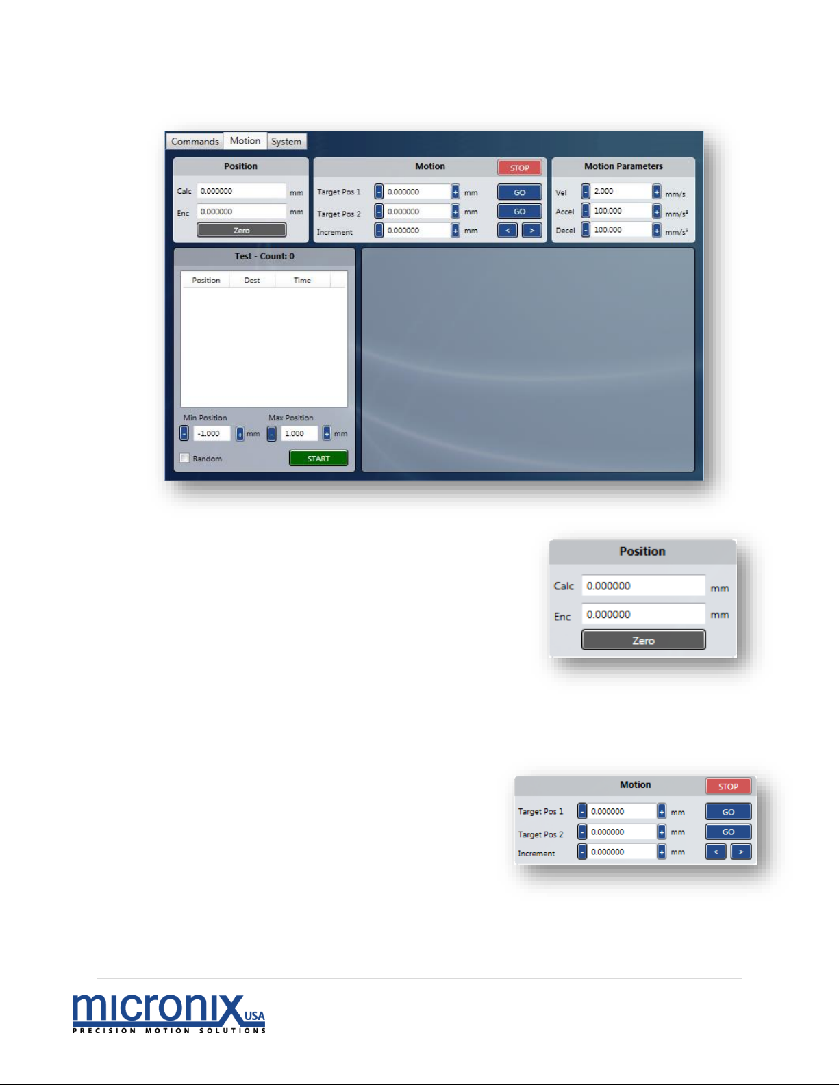
3. Motion – This section allows you to control movement with an easy to use user interface
a. Position
i. Zero - This button will set the current
position to zero for both the
calculated and encoder reading.
ii. Calc – This is the calculated position
based on the number of steps taken
(value in millimeters)
iii. Enc – This is the position as read by
the encoder assuming one is
attached (value in millimeters). If no
encoder is attached, this value reads 0.000000.
b. Motion – This section allows you to control the movement of a stage attached
to your MMC-10
i. Target Pos 1 – This field shows
the target for an absolute move
that will be executed upon
pressing the adjacent ‘GO’
button
ii. Target Pos 2 – This field shows
the target for an absolute move
that will be executed upon
pressing the adjacent ‘GO’ button
iii. Increment – This field indicates the amount of displacement a relative
move will travel upon pressing one of the adjacent ‘<’,’>’ buttons.
iv. STOP – This button will execute an Emergency Stop Command.
Motion section of Micronix MCP software
Page 12
11 | P a g e
Rev 2.01
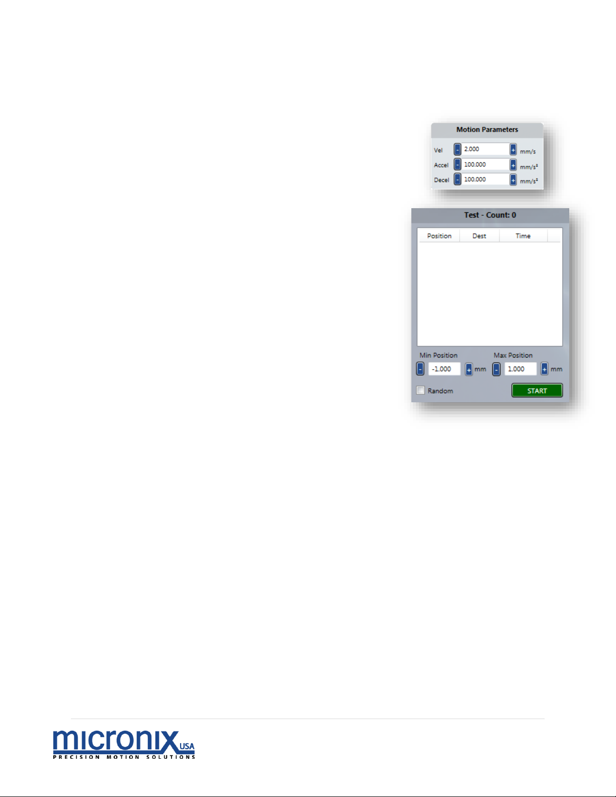
c. Motion Parameters – This section dictates some parameters for how a
movement function is executed.
i. Vel – This field indicates the controllers
current set velocity
ii. Accel – This field indicates the controllers
current set value for acceleration
iii. Decel – This field indicates the controllers
current set value for deceleration
d. Test
i. Max Position – Set this value to the
desired upper limit of travel
ii. Min Position - Set this value to the
desired lower limit of travel
iii. Random – If set the controller will send
random movements. If left unset, the
stage will run from the Max Position to
the Min Position as defined above.
iv. START – This will either execute the
random movements between limits or
the limit to limit run.
v. Position – This column is the start
position for the move that is occurring.
vi. Dest – This column is the destination
position for the move that is currently
occurring.
vii. Time – This column indicates the time
at which each move occurred.
Page 13
12 | P a g e
Rev 2.01
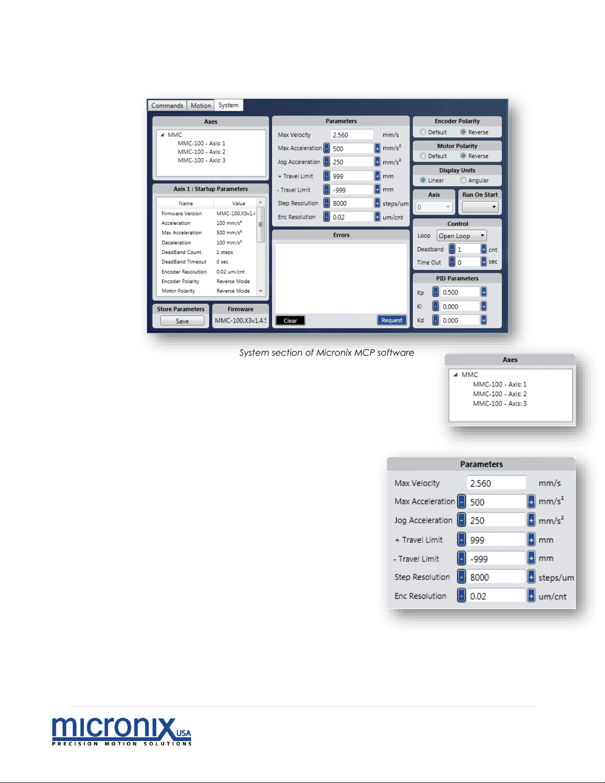
System section of Micronix MCP software
4. System
b. Axes – This field will show the stages attached to
the program along with associated axis number
c. Parameters – Upon opening the port as discussed
above, the MMC-10 MCP will populate the
following fields.
i. Max Velocity – Maximum allowed Velocity
ii. Max Acceleration – Maximum
Allowed Acceleration
iii. Jog Acceleration – Setting for
Jog Acceleration
iv. – Travel Limit – The soft travel
limit in the negative direction.
The controller will not allow the
stage to be moved outside this
limit
v. + Travel Limit – The soft travel
limit in the positive direction.
The controller will not allow the
stage to be moved outside this
limit
vi. Step Resolution – Steps per
micron resolution
vii. Enc Resolution – Microns per encoder count
Page 14
13 | P a g e
Rev 2.01
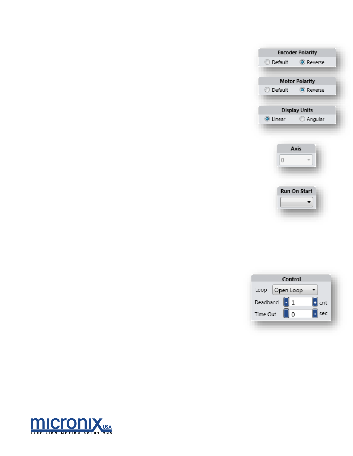
d. Encoder Polarity – This setting allows the user to flip
positive and negative directions for the Encoder.
e. Motor Polarity – This setting allows the user to flip
positive and negative directions for the Motor.
f. Display Units – This setting allows switching
between linear units (mm) and rotary units
(degrees).
g. Axis – This is a special command that needs to be
unlocked in the settings menu (Settings Menu ->
Advanced Tab -> Unlock Axis Select). This field is
associated with the ANR command and allows you to
reset the axis number for the current selected axis.
h. Run On Start – Here you can select which program you
would like the stage to execute upon start up. For more
on internal programs, see page 20 of this manual.
i. Control - This frame allows you to change options regarding feedback
control
i. Loop – Here you can choose between 4 different modes of control
1. Open Loop – This mode does not take encoder position
into account.
2. Clean Open Loop – This mode
also does not take encoder
position into account but
maintains a consistent pitch.
3. Open Loop Close deceleration –
This operation will run in clean
open loop mode and then read
from the encoder to correct its
position at the end of travel (Not
a constant velocity move).
4. Close Loop – This mode will constantly poll the encoder
and make corrections to achieve the target trajectory
(Constant velocity).
Page 15
14 | P a g e
Rev 2.01
ii. Deadband – This setting changes the
amount of error the closed loop control
mode will allow before trying to
reposition.
iii. Time Out – This setting allows you to
change the amount of time a closed
loop operation will search until it times
out.
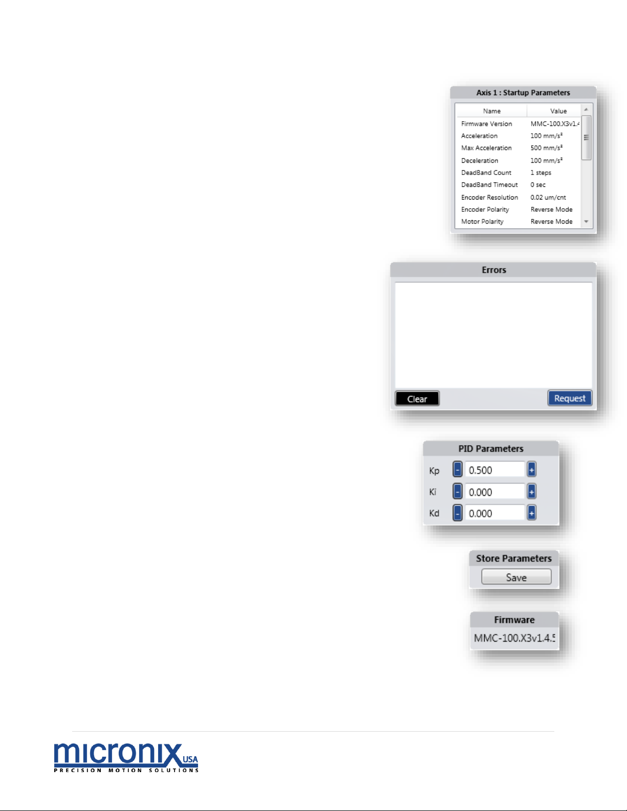
j. Startup Parameters – This field will populate with
the saved startup information for the selected
axis
k. Error
i. Clear – This button will clear
all error codes
ii. Request – This button will
dump all error codes to the
above terminal
l. PID Parameters - this field allows you
to change the parameters for closed
loop operation
i. Kp – Proportional Gain
ii. Ki – Integral Gain
iii. Kd – Differential Gain
m. Store Parameters – This will allow you to save the
settings you have entered as a file. This will allow you
to restore these parameters in the future if necessary.
n. Firmware – This Field indicates the Firmware version
installed in the MMC-10 controller
Page 16

15 | P a g e
Rev 2.01
2.5 Motion With and Without Encoders
Open Loop
If you have an open loop system (No Encoder), after opening the port from
part 2.3-1 you can test movement by entering a value in the increment field and
press either of the buttons. Be sure that the value is within the confines of
the travel limits. The stage should move and you should see the Calc field change.
Closed Loop
If you have a closed loop system (Attached Encoder), after opening the port
from part 2.3-1, ensure that the controller is in closed loop on the system page
(section 2.3-4h.). Then in the motion section enter a value in the increment field and
press either of the buttons. Be sure that the value is within the confines of
the travel limits. The stage should move and you should see the Calc and Enc fields
change and end at the same value.
3. Frequently Asked Questions
Why is my stage continuously running in one direction when set to closed loop (nFBK2, nFBK3)?
Most likely your encoder polarity is backwards. Use the nEPL? command to query the current
setting and then if it is 1 send nEPL0 if it is 0 send nEPL1.
How do I get my settings like velocity, acceleration, and limits to remain when I power down the
controller?
Use the nSAV command. This command writes all current settings to non-volatile RAM which will
allow them to persist between power cycles. If you would like to revert to the factory settings
simply use the nDEF command to revert the controller to its default parameters. (Note: to have
these persist between power cycles don’t forget to run the nSAV command)
What do the red and green LEDs mean?
The top LED is an address indicator. At startup it will flash from Red (unaddressed) to orange
(currently being addressed) to Green (addressed and ready for commands). The bottom LED is
an error indicator. When an error occurs, the LED will illuminate red. Use the nERR? command to
read all errors. By default, this LED will be off.
Why are the responses to my query commands coming back with garbage characters?
The communication bus for the MMC-10 is half-duplexed. It is important to ensure that you do
not send commands when there are responses coming back from the MMC-10. Also, please
ensure that the end of line character is a \r. If you sent \r\n a response will be sent at the same
time as the \n is on the bus and will cause bus contention.
4. Trouble Shooting
Difficulty Installing the Micronix Motion Control Platform
To run the Micronix MCP software, you will need the .NET Framework 4.0 or higher to already be
installed on the target computer. If the target computer has Windows 7 or later installed and is
current on all updates, .NET 4.0 should already be installed. If the target computer does not
have .NET 4.0 or you are unsure if the target computer has the .NET Framework 4.0, follow these
steps:
Page 17

16 | P a g e
Rev 2.01
a. Navigate to the support section of the Micronix Website at
http://www.micronixusa.com/motion/support/softwares.cfm
b. Download the file labeled DOT_NET Installation.
c. Run the application and follow the on screen instructions.
d. Return to section 2.2 and follow instructions. If you are still encountering problems,
contact Micronix support.
My MMC-10 is not being recognized as a com port by my system.
In some cases, due to a variety of factors, controllers will not be recognized as Com ports. Here
are steps to take to resolve this issue.
1. Make sure the device is powered on and the top LED is lit green. If the top LED is not lit green,
or if power is connected but no LEDs are lit, contact Micronix support.
2. Make sure the USB port the controller is plugged in to is functional. Try to plug the MMC-10 into
another USB port, or if using a USB hub try plugging the unit directly into the PC USB port. Try
another device like a thumb drive in the USB port and make sure it connects.
3. If the controller is powered on and plugged in to a functional USB port, but is still not being
recognized, try installing the Com Port drivers located at
http://www.micronixusa.com/motion/support/softwares.cfm
and restarting your computer. If this does not solve the problem, please contact Micronix
Support.
4. If the com port is recognized, but the Micronix Motion Control Platform is unable to
communicate with it, double check the setting of the port. To do this, open the control panel in
Microsoft windows and navigate to the device manager. Locate the com port associated with
the MMC unit (if there are multiple com ports open, unplug and replug the unit and look for the
com port that responds). Right click the com port associated with the MMC unit and select
“Properties” from the menu that appears. On the “Port Settings” tab, make sure the following
values are set.
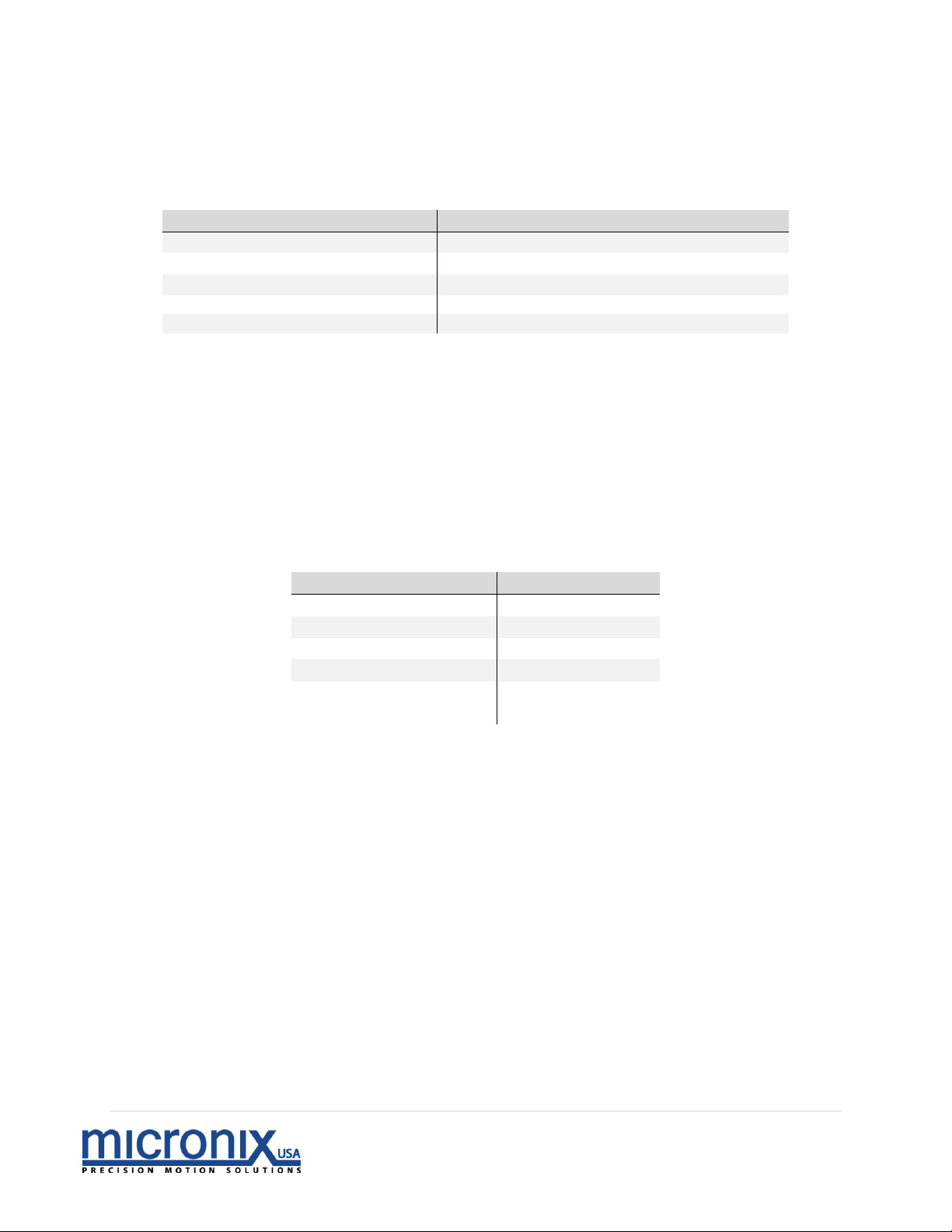
Software Parameter
Setting
Baud Rate
Data Bits
38400
8
Stop Bits
1
Parity
No
Handshake
No
Difficulty Identifying the Correct Com Port
In some cases, in which a large number of com ports are being used or com ports are tied up by
the system, it may be difficult to identify which com port is associated with which device. The
Micronix MCP programs drop down menu will display the most recently connected com port on
the bottom of the list. As such, an easy way to identify a device is to power cycle it, it should
now be the last listed com port.
Page 18
17 | P a g e
Rev 2.01
5. Technical Information
5.1 MMC-10 Specifications
Parameter
Description
Motor Type
Stick-slip piezo motors
Interface
USB 2.0 compliant/RS-485
Commands
ASCII Commands
Trajectory Mode
Trapezoidal velocity profile
Servo Clock
10 kHz
* Each axis requires 0.5A at peak usage. A up the individual axis power
requirements to determine the power supply amperage requirement.
5.2 Serial Port Setup
Below are the virtual RS-232 configuration settings necessary for correct
communication setup:
Software Parameter
Setting
Data Bits
8
Stop Bits
1
Parity
No
Handshake
No
Baud rate
38400
5.3 RJ11 RS485 Bus
The RS485 Intermodular RJ11 connector connects directly to the same Serial bus as the
FTDI interface above. In addition to being an RS-485 line, this connector also distributes
power and is responsible for addressing in situations where the auto address function is
being used. MMC-10 units can be connected in a daisy chain fashion, with the RS-485
Out of one unit plugging in to the RS-485 In of the next unit as shown in section 2.3 of this
manual. When daisy chaining, keep in mind that each unit has a peak current draw of
0.5A, so the number of daisy chained units is limited by the current rating of the power
supply being used.
Page 19

18 | P a g e
Rev 2.01
6. Operation
6.1 Axis Addressing
Auto Addressing is the default method of assigning axis numbers on start up.
Controllers are automatically assigned axis numbers on every power up, starting
with axis 1 and increasing consecutively until reaching axis 99.
Manual axis numbers may be assigned to a unique controller using the ANR
Command. This overrides Auto Addressing, as the controller stores the axis number
until reassigned or reset back to Auto Addressing. In the case of having a mix of
manually assigned and auto addressed controllers, the Auto Addressed axis
numbers increase consecutively after each manually assigned axis in the stack. For
example; in a stack of 5 controllers with the third controller manually assigned to
axis 10, the axis numbers will read: 1, 2, 10, 11, 12
If two controllers are accidentally assigned the same axis number, use a global
command to reset all controllers back to Auto Addressing.
6.2 Feedback Control
The MMC-10 has four different movement modes of operation. When executing a move
command, the controller will drive a stage differently when set to different modes. The
FBK command is used to switch between these modes.
The first mode (nFBK0) is a traditional Open Loop. It follows a standard trapezoidal
velocity characteristic. It bases the transition between acceleration, constant velocity
and deceleration on the resolution settings (nREZx) or the distance it travels in one pulse.
This is entirely theoretical and does not guarantee a set trajectory or end point.
The second mode (nFBK1) is also open loop, however this one does not follow the
standard trapezoidal velocity set by the user. Instead, it rounds off the velocity to an
even number of servo clocks per transition. This causes the motor to sound much cleaner
than the previous mode. However, it does sacrifice accuracy.
The third mode (nFBK2) is a version of closed loop; meaning it takes position data from an
attached encoder and uses it to ensure that it stops at the desired position. In this mode
the controller runs in the second open loop mode (nFBK1) until it reaches the
deceleration point. At this point it constantly reads from encoder and corrects its position
to arrive at the correct position. This, unlike the first two modes can guarantee position
within the specified deadband (DBN Command). However, this mode cannot guarantee
a known trajectory.
The fourth mode (nFBK3) is a more traditional closed loop. The controller will constantly try
to achieve an ideal trapezoidal velocity characteristic. Like the previous mode it too
can guarantee position final within the specified deadband.
Page 20
19 | P a g e
Rev 2.01
6.3 MLN, MLP, and User Defined References
The move to limit negative (MLN) and moves to limit positive (MLP) commands both
require the attached stage to have an encoder and will move the stage to end of travel
in their respective directions. The orientation of positive versus negative limits can be
changed using the limit direction (LDR) command. In addition, a user created reference
point can be created by moving to a limit, moving out of said limit the desired amount,
and then using the zero (ZRO) command to set both the calculated and encoder
positions to the value 0.000000mm. To return to this reference point, the user need only
use the move to absolute (MVA) command and move to the location 0.000000mm. See
Programming Example 3 of the Internal Programming section of this manual (Page 91)
for detailed instructions on creating a routine that runs on startup and automatically
creates this reference point.
7. Commands
7.1 Command Line Syntax
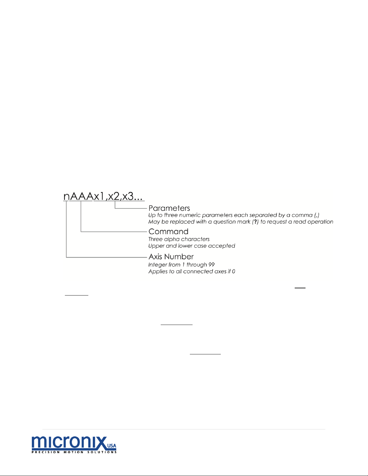
There are three components to every command prompt. The first is the “Axis
Number” which designates which controller, or axis, will receive the command. If
the “Axis Number” is 0, then the command will be sent globally to all connected
controllers. It is possible to connect up to 99 controllers; therefore the “Axis Number”
will be an integer value from 0 through 99.
The second component is the “Command”, which is always comprised of three
letters. Each command is outlined, along with its corresponding parameters, in the
Command Description section 5.9 of this manual.
The third and final component is the “Parameter”. This portion is command
dependent, meaning that the parameter value will change depending on the
specific requirements of the “Command”. Where applicable, a question mark (?)
may be substituted to initiate a read operation which will return information
regarding the particular command. There may be up to three separate parameters
for a particular command, each parameter value is separated by a comma (,).
All white space (blank spaces) are ignored in the command format. The following
are examples of equivalent commands:
4TRM13,45
4 TRM 13, 45
Page 21

20 | P a g e
Rev 2.01
7.2 Command Line Format
Commands are first executed in the order that they are input, then line by line. This
means that two commands on the same line are executed significantly closer to
each other than if they were on two separate lines. Each command is separated
by a semicolon (;) and every command line ends in a terminator (EX: carriage
return). The following is an example of a command line entry:
1MVR16;3MVR12 |Axis 1, Move 16 mm [16 degrees]; Axis 3, Move 12 mm [12 degrees]
Using multiple commands on the same command line allows for synchronization of
different commands to different axes. Up to 8 commands are allowed per
command line.
Only one read operation is allowed per line. The controller will not send information
unless requested to do so by a read operation.
7.3 Global Commands
Some commands have the option of being called globally. This means that you can
send the same command to all available axes. To do this, replace the axis number
of a global command with a ‘0’. For example; 0ACC 50 will set the acceleration of
all available axes to 50 mm/s2 [degrees/s2].
7.4 Multiple Parameters
When dealing with a command that has multiple parameters, it is possible to
change a single parameter by omitting numbers for the parameters that will
remain unchanged. For example; 4PID,,3 will only change the third parameter to a
new value, “3”.
7.5 Synchronous Move
It is possible to execute multiple motions at the same time by setting up and executing a
synchronous move. To set up a synchronous move, use the MSA and MSR commands.
These commands can be written on the same command line (up to 8 allowed) or on
separate lines followed by a line terminator. To execute the move, use the RUN
command on the proceeding command line followed by a line terminator. For example;
1MSA4;2MSA4;3MSA4 |Axis 1, Move 4mm; Axis 2, Move 4mm; Axis 3 Move 4mm
0RUN |Run Synchronous Move
Or
1MSA4 |Axis 1, Move 4mm
2MSA4 |Axis 2, Move 4mm
3MSA4 |Axis 3 Move 4mm
0RUN |Run Synchronous Move
Page 22

21 | P a g e
Rev 2.01
7.6 Internal Programming
A program may be used to save time when repeatedly using a sequence of
commands. Each controller or axis must be programmed individually; however,
multiple controllers may execute the same program at the same time. For a more
detailed look at the internal programming features of the MMC-10, see the
appendix of this manual.
7.7 Terminating Characters
When communicating with the controller, it is necessary to note the terminating
characters involved in transmitting and receiving data. To send data to the
controller, enter the desired commands in the command line followed by the new
line and carriage return terminating characters [\n\r], or just the carriage return
terminating character [\r]. When receiving, each line of data will be followed by
the new line terminating character [\n] and the final line will end in the new line
and carriage return terminating characters [\n\r]. The Hexadecimal value for new
line [\n] is 0X0A and for carriage return [\r] is 0X0D. The following is an example of
data transmission:
1VEL0.005 \n\r |Axis 1, Set velocity to .005 mm/s [degrees/s2] [New line, Carriage Return]
Page 23
22 | P a g e
Rev 2.01
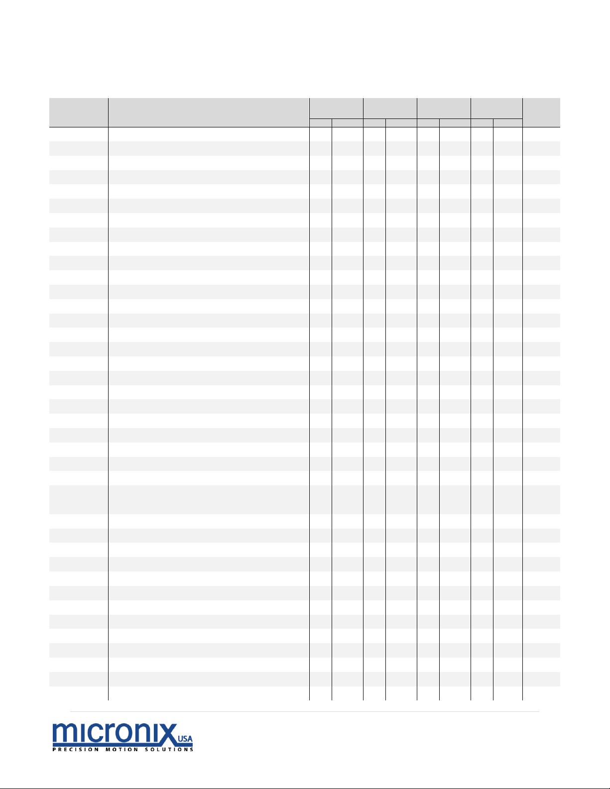
7.8 Summary of Commands
Command
Description
During
Motion
Real-time
Program
Global
Page
Set
Read
Set
Read
Set
Read
Set
Read
ACC
Acceleration
16
AMX
Maximum Allowable Acceleration
17
ANR
Set Axis Number
18
CER
Clear Errors
19
DAT
Dump Trace Data
20
DBD
Closed Loop Deadband
21
DEC
Deceleration
22
DEF
Restore Factory Defaults
23
EAD
Set Analog or Digital Encoder
24
ENC
Select Encoder Resolution
25
END
End Program Recording
26
EPL
Encoder Polarity
27
ERA
Erase Program
28
ERR
Read and Clear Errors
29
EST
Emergency Stop
30
EXC
Execute Program
31
FBK
Set Open or Closed Loop Mode
32
FMR
Upload Firmware
33
HCG
Home Configuration
34
HOM
Home
35
IOD
IO Pin Definition
36
IOF
IO Function
37
JAC
Jog Acceleration and Deceleration
38
JOG
Jog Mode
39
LDR
Limit Switch Direction
40
LCG
Limit Configuration
41
LIM
Limit Status
42
LST
Program List
43
LPL
Limit Switch Polarity
44
MLN
Move to Negative Limit
45
MLP
Move to Positive Limit
46
MOT
Toggle Motor On/Off
47
MPL
Motor Polarity
48
MSA
Synchronous Move – Absolute
49
MSR
Synchronous Move – Relative
50
MVA
Move Absolute
51
MVR
Move Relative
52
PGL
Loop Program
53
PGM
Begin Program Recording
54
Page 24
23 | P a g e
Rev 2.01
Continued…
see ANR command page 18 for more info
Command
Description
During
Motion
Real-time
Program
Global
Page
Set
Read
Set
Read
Set
Read
Set
Read
PGS
Run Program At Start-Up
55
PID
Set Feedback Constants
56
POS
Position
57
REZ
Set Resolution
58
RST
Perform Soft Reset
59
RUN
Start Synchronous move
60
SAV
Save Axis Settings
61
STA
Status Byte
62
STP
Stop Motion
63
SVP
Save Startup Position
64
SYN
Sync
65
TLN
Negative Soft Limit Position
66
TLP
Positive Soft Limit Position
67
TRA
Perform Trace
68
VEL
Velocity
69
VER
Firmware Version
70
VMX
Max. Allowable Velocity
71
VRT
Encoder Velocity
72
WST
Wait For Stop
73
WSY
Wait For Sync
74
WTM
Wait For Time Period
75
ZRO
Zero Position
76
ZZZ
Take Axis Offline
77
Page 25
24 | P a g e
Rev 2.01
7.9 Command Descriptions
Acceleration
During Motion
Real-time
Program
Global
Set
Read
Set
Read
Set
Read
Set
Read
Command
Description:
This command is used to set the desired acceleration for the
specified axis, distinct from the deceleration [DEC]. The
acceleration value must be less than the maximum
acceleration [AMX] for the command to be accepted.
Returns:
A read operation returns the acceleration value in mm/s2 for
the specified axis.
Syntax:
nACCx – Standard syntax
nACC? – Read acceleration value
0ACCx –All axes set acceleration value
Error [#]:
ACC? – Read operation with missing axis number [27]
nACC – Missing acceleration parameter [28]
Parameter
Description:
n[int] – Axis number
x[float] – Acceleration
? – Read acceleration value
Parameter
Range:
n – 0 to 99
x – 000.001 to AMX (500.000 mm/s
2
[degrees/s
2
])
Related
Commands:
DEC, VEL, JAC, AMX
Example:
3ACC0.250 |Axis 3, Set acceleration to 0.25mm/s
2
[degrees/s
2
]
-
4ACC? |Axis 4, Read acceleration value
Page 26
25 | P a g e
Rev 2.01
Maximum Allowable Acceleration
During Motion
Real-time
Program
Global
Set
Read
Set
Read
Set
Read
Set
Read
Command
Description:
This command is used to set the maximum allowable
acceleration for the specified axis.
Returns:
A read operation returns the maximum allowable
acceleration value in mm/s2 for the specified axis.
Syntax:
nAMXx – Standard syntax
nAMX? – Read maximum allowable acceleration value
0AMXx – All axes set maximum allowable acceleration value
Error [#]:
AMX? – Read operation with missing axis number [27]
nAMX – Missing maximum acceleration parameter [28]
Parameter
Description:
n[int] – Axis number
x[float] – Maximum acceleration
? – Read maximum allowable acceleration value
Parameter
Range:
n – 0 to 99
x – 000.001 to 500.000 mm/s
2
[degrees/s
2
]
Related
Commands:
DEC, VEL, JAC, VMX, ACC
Example:
2AMX1.500 |Axis 2, Set max acceleration to 1.500
mm/s
2
[degrees/s2]
-
6AMX? |Axis 6, Read max acceleration value
Page 27
26 | P a g e
Rev 2.01
Set Axis Number
During Motion
Real-time
Program
Global
Set
Read
Set
Read
Set
Read
Set
Read
Command
Description:
This command is used to override Auto Addressing by
manually assigning an axis number to a controller. Auto
Addressing is the default method of assigning axis numbers
on power up and may be reassigned to an axis by
substituting a “0” for the parameter value. Simultaneous
axis swapping is possible by using multiple ANR commands
on the same command line. A save [SAV] followed by a
controller reset [RST] is required for changes to take effect.
If wo or more axes in the same stack have the same address,
bus contention will occur causing invalid controller
response and erratic behavior (including inaccessible axes).
To correct this, issue the commands 0ANR0, then 0SAV,
followed by 0RST to restore default auto addressing.
This command can be called globally by specifying a ‘0’
for the axis number; however it will only work if the new
axis number parameter is set to ‘0’ for auto-addressing.
Returns:
A read operation returns the following axis number values
for the specified axis:
0 – Auto Addressing assigned (default)
1-99 – Manually assigned, axis number displayed
Syntax:
nANRx – Standard syntax
nANR? – Read axis number value
Error [#]:
ANR? – Read operation with missing axis number [27]
nANR – Missing new axis number parameter [28]
ANRx – Missing axis number [30]
Parameter
Description:
n[int] – Axis number
x[int] – New axis number, 0 for Auto Addressing
? – Read axis number value
Parameter
Range:
n – 0 to 99
x – 0 to 99
Related
Commands:
RST
Example:
5ANR1;1ANR5 |Simultaneous axis swapping: Axis 5,
Set to axis 1; Axis 1, Set to axis 5
-
4ANR0 |Axis 4 Set to Auto Addressing.
However it will
remain axis 4 until the MMC-100 is reset
Page 28
27 | P a g e
Rev 2.01
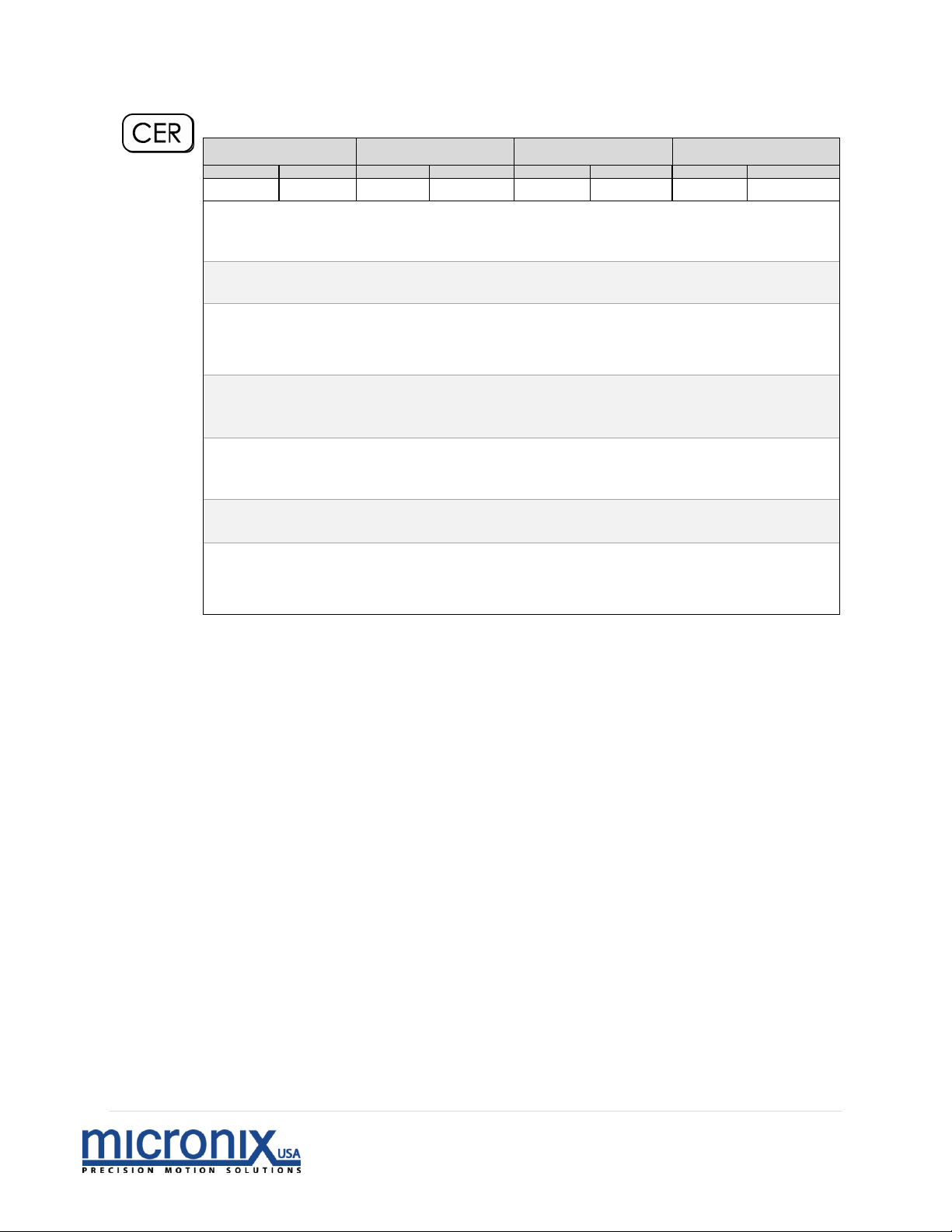
Clear Errors
During Motion
Real-time
Program
Global
Set
Read
Set
Read
Set
Read
Set
Read
Command
Description:
This command is used to clear all error messages without
reading them.
Returns:
A read operation cannot be used with this command.
Syntax:
nCER – Standard syntax
0CER – All axes clear error messages
Parameter
Description:
n[int] – Axis number
Parameter
Range:
n – 0 to 99
Related
Commands:
ERR
Example:
1CER | Axis 1, clear error messages
–
0CER | All axes, clear error messages
Page 29
28 | P a g e
Rev 2.01
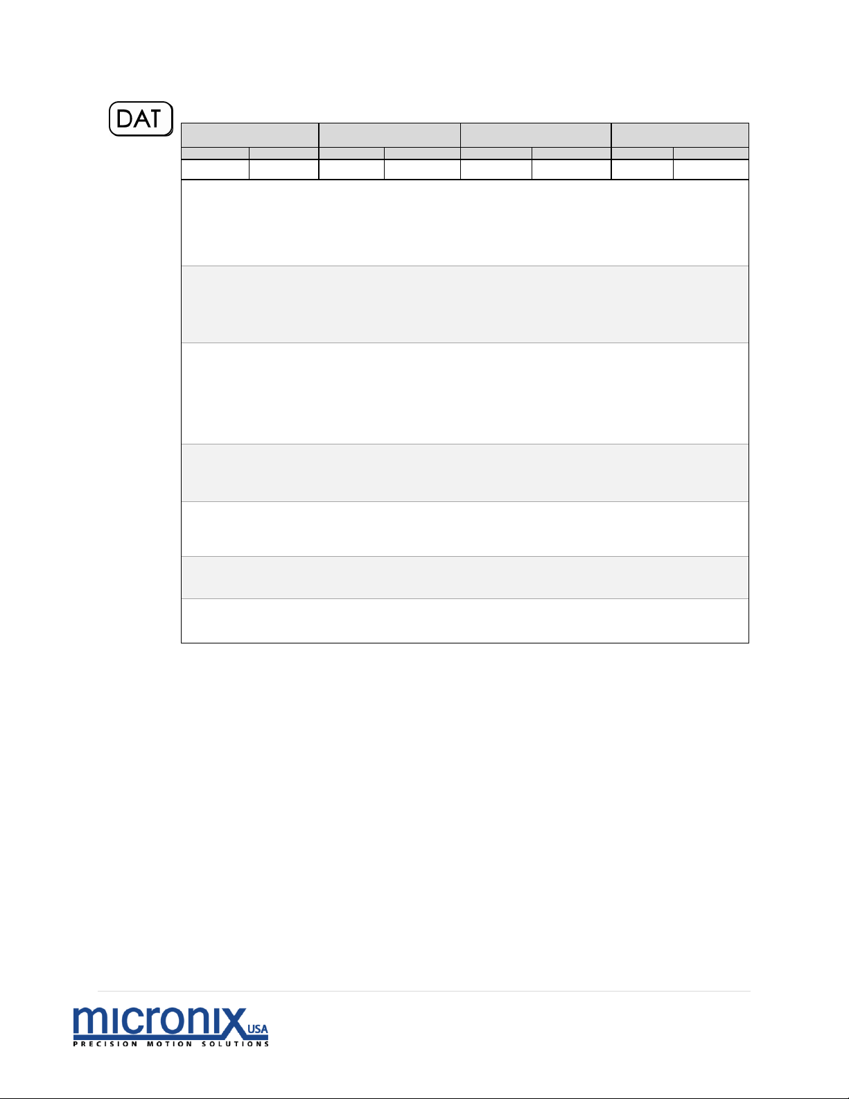
Dump Trace Data
During Motion
Real-time
Program
Global
Set
Read
Set
Read
Set
Read
Set
Read
Command
Description:
This command is used to read trace data from a specified
axis initially recorded by the trace command [TRA]. The
retrieved trace data set is dumped from the controller,
consequently allowing the data to be retrieved only once.
Returns:
A read operation returns the trace data values for the
specified axis in the following format:
[Theoretical Position (Encoder Counts)],[Actual
Position(Encoder Counts)], [DAC Value], [Not Used]
Syntax:
nDAT? – Read trace data values
Error [#]:
DAT? – Read operation with missing axis number [27]
nDAT – Missing read operation parameter [28]
Parameter
Description:
n[int] – Axis number
? – Read trace data values
Parameter
Range:
n – 1 to 99
Related
Commands:
TRA
Example:
11DAT? |Axis 11, Read trace data values
Page 30
29 | P a g e
Rev 2.01
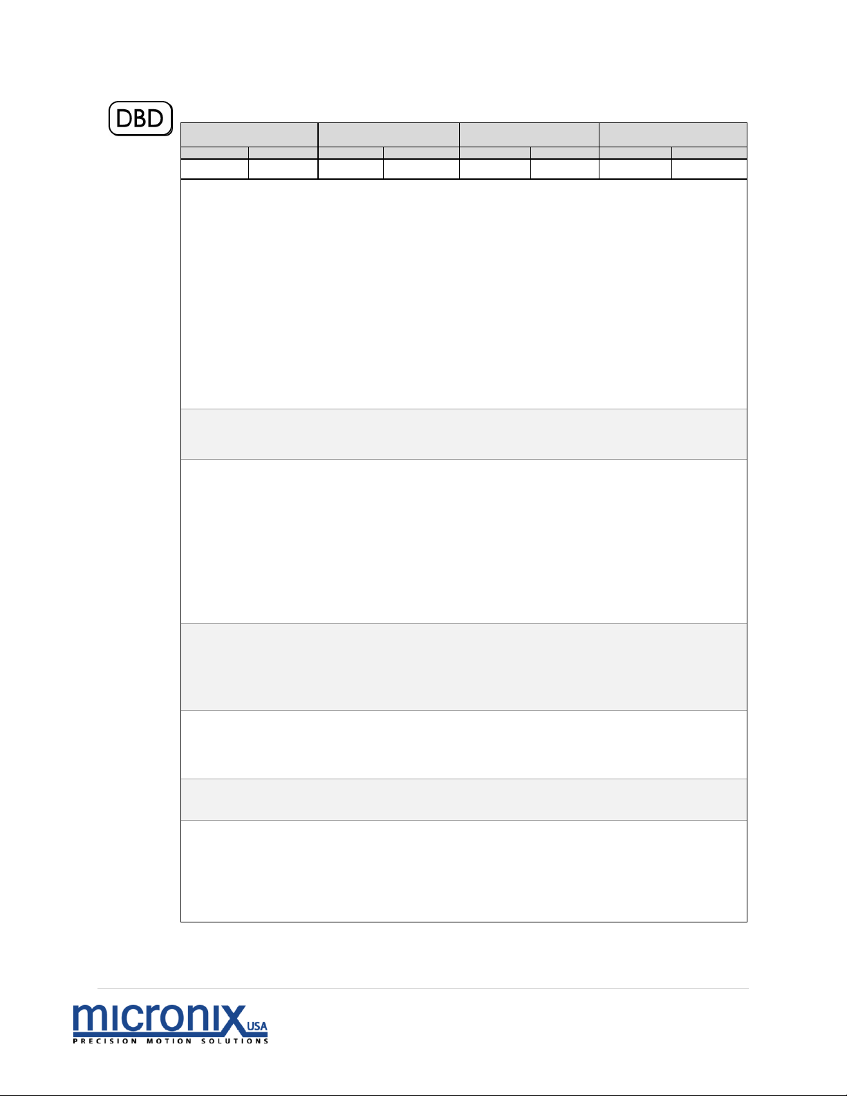
Closed Loop Deadband
During Motion
Real-time
Program
Global
Set
Read
Set
Read
Set
Read
Set
Read
Command
Description:
This command is used to set the acceptable deadband and
deadband timeout values.
Deadband refers to the number of encoder counts (±) from
the target that is considered acceptable. If the parameter (x1)
is set to “0”, the controller will continuously oscillate
around the target.
Deadband timeout refers to the amount of time that the
controller will try to move into the deadband area. If the
parameter (x2) is set to “0”, the controller will seek
continuously.
Returns:
A read operation returns the deadband and deadband
timeout values for the specified axis.
Syntax:
nDBDx1,x2 – Standard syntax
nDBD? – Read deadband and deadband timeout values
0DBDx1,x2 – All axes set deadband and deadband timeout values
Error [#]:
DBD? – Read operation with missing axis number [27]
nDBD – Missing deadband and deadband timeout parameter
values [28]
Parameter
Description:
n[int] – Axis number
x1[int] – Deadband
x2[float] – Deadband timeout
? – Read deadband and deadband timeout values
Parameter
Range:
n – 0 to 99
x1 – Encoder dependent, 0 for continuous, Encoder Counts
x2 – Encoder dependent, 0 for infinite, Seconds (default 0)
Related
Commands:
ENC, EPL
Example:
1DBD10,1 |Axis 1, Set deadband to 10 encoder counts
& deadband timeout to 1 second
-
4DBD5,0 |Axis 4, Set deadband to 5 encoder counts &
deadband timeout to infinite
Page 31
30 | P a g e
Rev 2.01
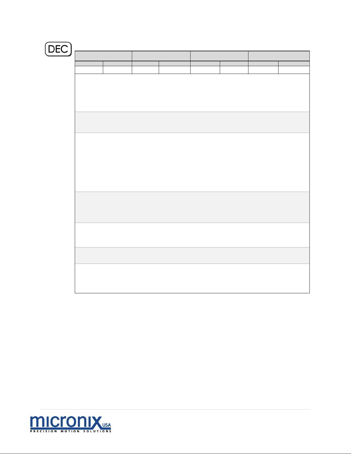
Deceleration
During Motion
Real-time
Program
Global
Set
Read
Set
Read
Set
Read
Set
Read
Command
Description:
This command is used to set the desired deceleration for the
specified axis, distinct from the acceleration [ACC]. The
deceleration value must be less than the maximum
acceleration value [AMX] for the command to be accepted.
Returns:
A read operation returns the deceleration value in mm/s2 for
the specified axis.
Syntax:
nDECx – Standard syntax
nDEC? – Read deceleration value
0DECn – All axes set deceleration value
Error [#]:
DEC? – Read operation with missing axis number [27]
nDEC – Missing deceleration parameter [28]
Parameter
Description:
n[int] – Axis number
x[float] – Deceleration
? – Read deceleration value
Parameter
Range:
n – 0 to 99
x – 000.001 to AMX (500.000 mm/s
2
) [degrees/s
2
]
Related
Commands:
ACC, AMX, VEL
Example:
2DEC1.25 |Axis 2, Set deceleration to 1.25 mm/s
2
[degrees/s2]
-
7DEC? |Axis 7, Read deceleration value
Page 32
31 | P a g e
Rev 2.01
Restore Factory Defaults
During Motion
Real-time
Program
Global
Set
Read
Set
Read
Set
Read
Set
Read
Command
Description:
This command restores the factory default parameters.
Returns:
A read operation is not available with this command.
Syntax:
nDEF – Standard syntax
Error [#]:
DEF – Missing axis number [30]
Parameter
Description:
n[int] – Axis number
Parameter
Range:
n – 1 to 99
Related
Commands:
SAV
Example:
1DEF |Axis 1, set all default parameters
Page 33
32 | P a g e
Rev 2.01
Set Analog or Digital Encoder
During Motion
Real-time
Program
Global
Set
Read
Set
Read
Set
Read
Set
Read
Command
Description:
This command is used to specify whether the encoder signal
for a specified axis is analog or digital.
Returns:
A read operation returns the following encoder mode values
for the specified axis:
0 – Digital
1 – Analog
Syntax:
nEADx – Standard syntax
nEAD? – Read encoder mode value
0EADx – All axes set encoder value
Error [#]:
xEAD – Missing encoder mode parameter [28]
EAD? – Read operation with missing axis number [27]
Parameter
Description:
n[int] – Axis number
x[int] – Encoder mode
? – Read encoder mode value
Parameter
Range:
n – 0 to 99
x – 0 for digital, 1 for analog
Related
Commands:
ENC
Example:
9EAD0 |Axis 9, Set encoder to digital input
Page 34
33 | P a g e
Rev 2.01
Set Encoder Resolution
During Motion
Real-time
Program
Global
Set
Read
Set
Read
Set
Read
Set
Read
Command
Description:
This command is used to set the desired encoder resolution
for the specified axis. When a digital encoder is connected,
encoder resolution is determined by the encoder itself and
the ENC setting will need to reflect this value. Analog
encoder resolution is set by the controller.
Returns:
A read operation returns the encoder resolution value for the
specified axis.
Syntax:
nENCx – Standard syntax
nENC? – Read encoder resolution value
0ENCx – All axes execute encoder resolution value
Error [#]:
ENC? – Read operation with missing axis number [27]
nENC – Missing encoder resolution parameter [28]
Parameter
Description:
n[int] – Axis number
x[float] – Encoder resolution
? – Read encoder resolution value
Parameter
Range:
n – 0 to 99
x – 0.001 to 999.999 µm/count (milli-degrees/count)
Related
Commands:
EAD
Example:
2ENC10 |Axis 2, Set encoder resolution to 10 microns/count
(10 milli- degrees/count)
Page 35
34 | P a g e
Rev 2.01
End Program Recording
During Motion
Real-time
Program
Global
Set
Read
Set
Read
Set
Read
Set
Read
Command
Description:
This command is used to exit out of program recording
mode, which is initiated by the PGM command. The END
command must be placed separately on the last line of the
program sequence. The resulting program is saved upon exit
for later use.
Returns:
A read operation is not available with this command.
Syntax:
nEND – Standard syntax
Error [#]:
END – Missing axis number [30]
Parameter
Description:
n[int] – Axis number
Parameter
Range:
n – 1 to 99
Related
Commands:
REC, EXC, PGM
Example:
1PGM |Axis 1, Begin program recording
1VEL1;1ACC.5 |Axis 1, Set velocity value to 1 mm/s; Axis 1, Set
acceleration value to 0.5 mm/s
2
[degrees/s2]
1END |Axis 1, End program recording
Page 36
35 | P a g e
Rev 2.01
Encoder Polarity
During Motion
Real-time
Program
Global
Set
Read
Set
Read
Set
Read
Set
Read
Command
Description:
This command is used to switch the encoder signal polarity
for the specified axis, which determines the physical
direction of travel that the stage reads as positive (by
default, moving away from where the wires enter the base of
the stage is positive).
NOTE: EPL, MPL and LDR must all be changed together to
maintain proper functionality, changing one of these values
without changing the rest will result in improper stage
behavior.
Returns:
A read operation returns the following encoder polarity
values for the specified axis:
0 – Normal operation
1 – Reverse operation
Syntax:
nEPLx – Standard syntax
nEPL? – Read encoder polarity value
0EPLx – All axes execute encoder polarity value
Error [#]:
EPL? – Read operation with missing axis number [27]
nEPL – Missing encoder polarity parameter [28]
Parameter
Description:
n[int] – Axis number
x[float] – Encoder polarity
? – Read encoder polarity value
Parameter
Range:
n – 0 to 99
x – 0 for normal operation, 1 for reverse operation
Related
Commands:
DBD
Example:
13EPL0 |Axis 13, Set encoder polarity to normal
operation
-
6EPL1 |Axis 6, Set encoder polarity to reverse
operation
Page 37
36 | P a g e
Rev 2.01
Erase Program
During Motion
Real-time
Program
Global
Set
Read
Set
Read
Set
Read
Set
Read
Command
Description:
This command is used to erase a specified program from an
axis. Before recording a program, use the LST command to
see what program numbers are available for that axis. There
are 16 program numbers available allowing up to 16
programs to be stored. An existing program cannot be
overwritten and must be erased first. Therefore, use this
command to erase the specified program and make space for
a new one.
Returns:
A read operation is not available with this command.
Syntax:
nERAx – Standard syntax
Error [#]:
ERAx – Missing axis number [30]
nERA – Missing program number parameter [28]
Parameter
Description:
n[int] – Axis number
x[int] – Program number to be erased
Parameter
Range:
n – 1 to 99
x – 1 to 16
Related
Commands:
LST
Example:
5ERA4 |Axis 8, Erase program 4
Page 38
37 | P a g e
Rev 2.01
Read and Clear Errors
During Motion
Real-time
Program
Global
Set
Read
Set
Read
Set
Read
Set
Read
Command
Description:
This command is used to read and clear any pending error
messages.
Returns:
A read operation returns a list of error messages for the
specified axis in the following format. “AAA” signifies the
specific command name that the error corresponds to.
Error Number – Description [AAA]
Syntax:
nERR? – Standard syntax
Error [#]:
ERR? – Read operation with missing axis number [123]
Parameter
Description:
n[int] – Axis number
? – Read error messages
Parameter
Range:
n – 1 to 99
Related
Commands:
None
Example:
3ERR? | Axis 3, Read error messages
Page 39
38 | P a g e
Rev 2.01
Emergency Stop
During Motion
Real-time
Program
Global
Set
Read
Set
Read
Set
Read
Set
Read
Command
Description:
This command is used to stop a specific axis or all
connected axes simultaneously in case of an emergency.
The controller executes the largest possible deceleration.
Returns:
A read operation is not available with this command.
Syntax:
nEST – Standard syntax
0EST – All axes execute emergency stop
Parameter
Description:
n[int] – Axis number
Parameter
Range:
n – 0 to 99
Related
Commands:
STP
Example:
8EST |Axis 8, Emergency stop
-
0EST |All axes, Emergency stop
Page 40
39 | P a g e
Rev 2.01
Execute Program
During Motion
Real-time
Program
Global
Set
Read
Set
Read
Set
Read
Set
Read
Command
Description:
This command is used to execute a specified program for
one or multiple axes. If executing a program globally, all
connected axes should have individual programs stored
under the specified program number prior to execution.
Returns:
A read operation is not available with this command.
Syntax:
nEXCx – Standard syntax
0EXCx – All axes execute program
Error [#]:
nEXC – Missing program number parameter [123]
Parameter
Description:
n[int] – Axis number
x[float] – Program number to be executed
Parameter
Range:
n – 0 to 99
x – 1 to 64
Related
Commands:
PGM
Example:
4EXC5 |Axis 4, Execute program 5
-
0EXC2 |All axes, Execute program 2
Page 41
40 | P a g e
Rev 2.01
Set Open or Closed Loop Mode
During Motion
Real-time
Program
Global
Set
Read
Set
Read
Set
Read
Set
Read
Command
Description:
This command is used to select the feedback mode of the
controller. See section 4.2 for more details
Returns:
A read operation returns the following loop mode values for
the specified axis:
1. – Open Loop [default]
2. – Clean Open Loop
3. – Clean Open Loop Movement, Closed Loop
deceleration
4. – Closed Loop
Syntax:
nFBKx – Standard syntax
nFBK? – Read encoder mode value
Error [#]:
FBKx – Missing axis number [30]
FBK? – Read operation with missing axis number [27]
nFBK – Missing closed/open loop parameter [28]
Parameter
Description:
n[int] – Axis number
x[float] – Open/closed loop mode
? – Read encoder mode value
Parameter
Range:
n – 1 to 99
x – 0 for open loop mode, 1 for clean sounding open loop mode, 2 for open
loop with closed loop deceleration, 3 closed loop
Related
Commands:
ENC, EAD, EPL, DBD
Example:
2FBK3 |Axis 2, Set closed loop mode
Page 42
41 | P a g e
Rev 2.01
Home Configuration
During Motion
Real-time
Program
Global
Set
Read
Set
Read
Set
Read
Set
Read
Command
Description:
This command is used to select the direction of motion
when the Home [HOM] command is initialized.
Returns:
A read operation returns the current direction setting:
0 – Home starts in the direction of the negative limit
1 – Home starts in the direction of the positive limit
Syntax:
nHCGx – Standard syntax
0HCGx – All axes set direction
nHCG? – Read direction setting
Error [#]:
HCG? – Read operation with missing axis number [27]
nHCG – Missing direction setting [28]
Parameter
Description:
n[int] – Axis number
x [int] – Set direction of motion.
Parameter
Range:
n – 0 to 99
x – 0 for setting motion in the direction of the negative limit
1 for setting motion in the direction of the positive limit
Related
Commands:
HOM
Example:
3HCG0 |Axis 3, Set initial direction of Home
command towards the negative limit
-
0HCG1 |All Axes, Set initial direction of Home
command towards the
positive limit
Page 43
42 | P a g e
Rev 2.01
Home
During Motion
Real-time
Program
Global
Set
Read
Set
Read
Set
Read
Set
Read
Command
Description:
This command is used to find the home position for a
specified axis. An error will occur if there is no encoder
signal at the time of execution. Home is configured using
the HCG command. This command will jog the stage until it
reaches the limit configured with the HCG command. It will
then acquire the home position by looking for the index.
This command blocks all communication over the serial port
during motion.
Returns:
A read parameter returns the following calibration values for
the specified axis:
0 – Not calibrated to home position
1 – Calibrated to home position
Syntax:
nHOM – Standard syntax
nHOM? – Returns 1 if homed since last startup otherwise returns 0
0HOM – All axes execute home position
Error [#]:
HOM? – Read operation with missing axis number [27]
Parameter
Description:
n[int] – Axis number
Parameter
Range:
n – 0 to 99
Related
Commands:
HCG
Example:
1HOM |Axis 1, Move to home position
Page 44
43 | P a g e
Rev 2.01
Set IO Definition
During Motion
Real-time
Program
Global
Set
Read
Set
Read
Set
Read
Set
Read
Command
Description:
This command is used to select Input or Output for one of
the IO pins on the 8-Pin Din connector.
Returns:
A read operation is not available with this command.
Syntax:
nIODx1,x2 – Standard syntax
nIOD? – Read encoder mode value
Error [#]:
IODx1,x2 – Missing axis number [30]
IOD? – Read operation with missing axis number [27]
nIOD – Missing closed/open loop parameter [28]
Parameter
Description:
n[int] – Axis number
x1[int] – IO Pin
x2[int] – Input/ Output
? – Read encoder mode value
Parameter
Range:
n – 1 to 99
x1 – 1 – IO1 (output only)
2 – IO2
3 – IO3
4 – IO4
x2 – 0 – Output
1 - Input
Related
Commands:
IOF
Example:
2IOD2,1 |Axis 2, Set IO2 to an Input
Page 45
44 | P a g e
Rev 2.01
Set IO Function
During Motion
Real-time
Program
Global
Set
Read
Set
Read
Set
Read
Set
Read
Command
Description:
This command is used to select the function of an IO pin.
Returns:
A read operation is not available with this command.
Syntax:
nIOFx1,x2 – Standard syntax
nIOF? – Read encoder mode value
Error [#]:
IOFx1,x2 – Missing axis number [30]
IOF? – Read operation with missing axis number [27]
nIOF – Missing closed/open loop parameter [28]
Parameter
Description:
n [int] – Axis number
x1[int] – IO Pin
x2 [int] – IO Function
? – Read encoder mode value
Parameter
Range:
n – 1 to 99
x1 – 1 – IO1
2 – IO2
3 – IO3
4 – IO4
x2 – 0 – No function
1 – Trace data acquisition on trigger
2 – Output pulse trigger when in position
3 – Output level when in position
Related
Commands:
IOD
Example:
2IOF2,1 |Axis 2, Set IO2 to data logging
trigger
Page 46
45 | P a g e
Rev 2.01
Jog Acceleration and Deceleration
During Motion
Real-time
Program
Global
Set
Read
Set
Read
Set
Read
Set
Read
Command
Description:
This command is used to set the desired value for the jog
acceleration and deceleration for a specified axis. The
controller will not allow for JAC values that are greater than
AMX.
Returns:
A read operation returns the jog acceleration and
deceleration value in mm/s2 for the specified axis.
Syntax:
nJACx – Standard syntax
0JACx – All axes execute acceleration value
nJAC? – Read acceleration value
Error [#]:
JAC? – Read operation with missing axis number [27]
nJAC – Missing acceleration parameter [28]
Parameter
Description:
n[int] – Axis number
x[float] – Acceleration
? – Read acceleration value
Parameter
Range:
n – 0 to 99
x – .001 to 500.000 mm/s
2
[degrees/s
2
]
Related
Commands:
ACC, DEC, AMX
Example:
4JAC0.1 |Axis 4, Set jog acceleration &
deceleration to 0.1 mm/s2 [degrees/s
2
]
Page 47
46 | P a g e
Rev 2.01
Jog Mode
During Motion
Real-time
Program
Global
Set
Read
Set
Read
Set
Read
Set
Read
Command
Description:
This command is used to jog a specific axis, or move
continuously in a direction with no target position. The jog
velocity is a percentage of the maximum velocity and may
be changed on-the-fly by sending another JOG command
during motion.
Returns:
A read operation is not available with this command.
Syntax:
nJOGx – Standard syntax
Error [#]:
JOGx – Missing axis number [30]
nJOG – Missing velocity parameter [28]
Parameter
Description:
n[int] – Axis number
x[float] – Velocity
Parameter
Range:
n – 1 to 99
x – 0 to ±100.000 % (of maximum velocity)
Related
Commands:
JAC
Example:
4JOG10 |Axis 4, Jog at 10% maximum velocity
2JOG-50 |Axis 2, Jog in the negative direction at 50%
maximum velocity
Page 48
47 | P a g e
Rev 2.01
Limit Configuration
During Motion
Real-time
Program
Global
Set
Read
Set
Read
Set
Read
Set
Read
Command
Description:
This command selects how the stage will detect it’s end limits,
using a limit switch or using the encoder to detect a hard stop.
Returns:
A read operation returns the selected limit type.
Syntax:
nLCGx – Standard syntax
Error(s):
LCGx – Missing axis number [30]
nLCG – Missing program number parameter [28]
Parameter
Description:
n[int] – Axis number
x[int] – 0 – ignore [default]
1– active
Parameter
Range:
n – 1 to 99
x – 0 – ignore [default]
1 – Home and MLN/MLP use Soft Limits
2 – Limits Switches Enabled
3 – Home and MLN.MLP use Soft Limits and Limit Switches enabled
Related Commands:
LPL
Example:
1LCG1 |Axis 1, set limit switches active
Page 49
48 | P a g e
Rev 2.01
Positive/ Negative Limit Location
During Motion
Real-time
Program
Global
Set
Read
Set
Read
Set
Read
Set
Read
Command
Description:
Determines orientation of Positive limit, and negative limit.
NOTE: EPL, MPL and LDR must all be changed together to
maintain proper functionality, changing one of these values without
changing the rest will result in improper stage behavior.
Returns:
A read operation returns the following limit direction values for the
specified axis:
0 – Normal orientation
1 – Reverse orientation
Syntax:
nLDRx – Standard syntax
nLDR? – Read velocity value
0LDRx – Missing axis number, all axes set limit direction
Error [#]:
LDR? – Read operation with missing axis number [27]
nLDR – Missing limit parameter [28]
Parameter
Description:
n[int] – Axis number
x[int] – limit direction value
? – Read limit direction value
Parameter
Range:
n – 0 to 99
x – 0 or 1
Related Commands:
Example:
1LDR1 |Axis 1, set to reverse orientation
-
5LDR? |Axis 5, Read limit switch orientation
Page 50
49 | P a g e
Rev 2.01
Limit Status
During Motion
Real-time
Program
Global
Set
Read
Set
Read
Set
Read
Set
Read
Command
Description:
Returns the status of both limit switches in the form LSP, LSN.
This is useful for limit switch configuration.
Returns:
A read operation returns current limit status for the specified axis.
Syntax:
nLIM? – Standard syntax
Error [#]:
LIM? – Read operation with missing axis number [123]
Parameter
Description:
n[int] – Axis number
? – Read limit switches
Parameter
Range:
n – 1 to 99
Related Commands:
None
Example:
6LIM? | Axis 6, read current limit status
Page 51
50 | P a g e
Rev 2.01
Program List
During Motion
Real-time
Program
Global
Set
Read
Set
Read
Set
Read
Set
Read
Command
Description:
This command is used to display the individual commands
entered by the user to create the specified program. NOTE:
Commands are returned sequentially and individually,
which means in the Micronix GUI they will be listed from
bottom (first returned) to top (last returned).
Returns:
A read operation returns the program table for the specified
axis.
Syntax:
nLST? – Standard syntax
Error [#]:
1LST? – Read Not Available For This Command [38]
Parameter
Description:
n[int] – Axis number
x[int] – Program# to be read
Parameter
Range:
n – 1 to 99
x – 1 to 16
Related
Commands:
None
Example:
6LST1 | Axis 6, return program 1 list of commands
Page 52
51 | P a g e
Rev 2.01
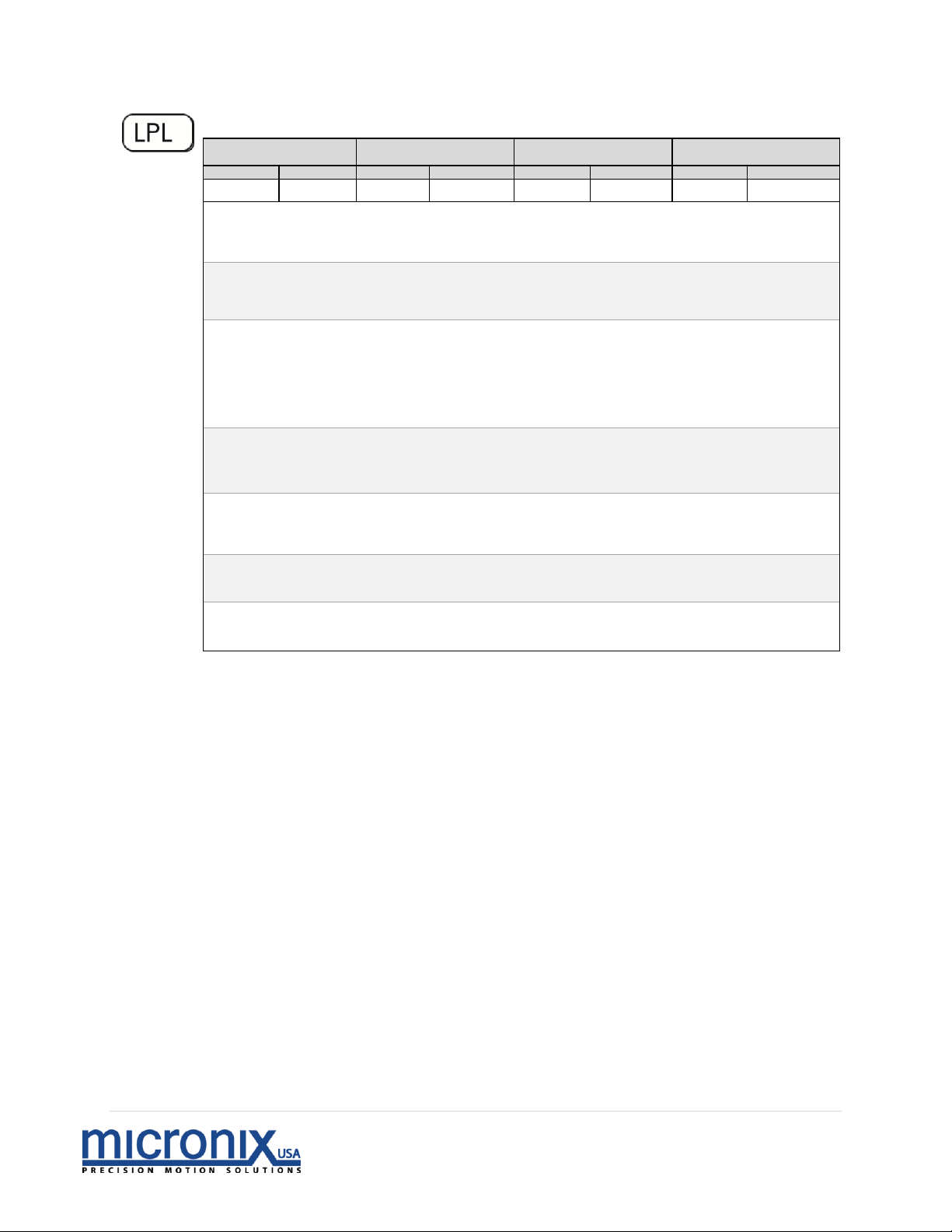
Limit Switch Polarity
During Motion
Real-time
Program
Global
Set
Read
Set
Read
Set
Read
Set
Read
Command
Description:
This command sets whether the limit switch inputs are
active high[1] or low[0]
Returns:
A read operation returns the limit polarity value.
Syntax:
nLPLx – Standard syntax
Error(s):
LPLx – Missing axis number [30]
nLPL – Missing program number parameter [28]
Parameter
Description:
n[int] – Axis number
x – 0 –Active Low
– 1 – Active High
Parameter
Range:
n – 1 to 99
x – 0 – active low [default]
1– active high
Related
Commands:
LCG
Example:
6LPL1 | Axis 5, limit switches set to active high
Page 53
52 | P a g e
Rev 2.01
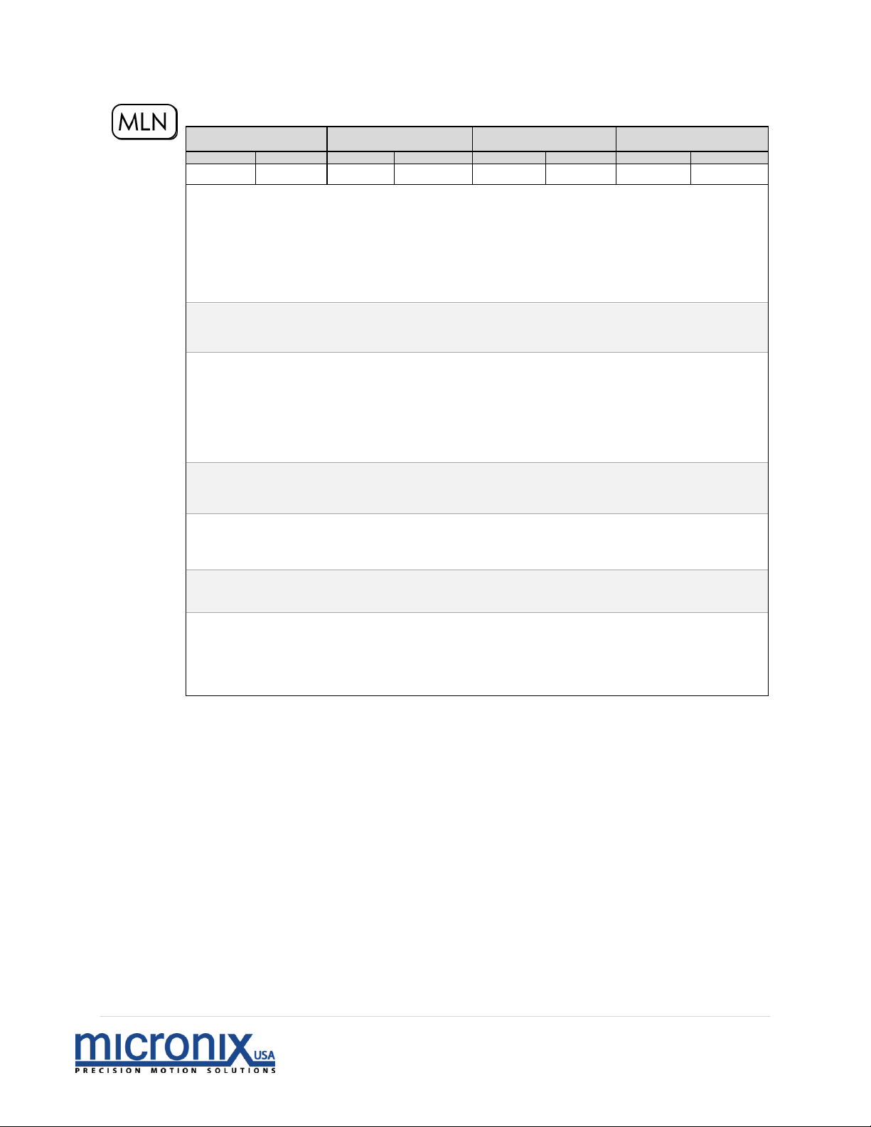
Move to Negative Limit
During Motion
Real-time
Program
Global
Set
Read
Set
Read
Set
Read
Set
Read
Command
Description:
This command initiates a move to the negative limit
position. Upon reaching the negative hard limit the
controller will then move the stage back from the hard limit
and stop. If hard stop detection using the encoder (LCG0) is
active, an error will occur if there is no encoder signal at the
time of execution.
Returns:
A read operation is not available with this command.
Syntax:
nMLN – Standard syntax
0MLN – All axes execute move to negative limit position
Error [#]:
MLN – Missing axis number [30]
Parameter
Description:
n[int] – Axis number
Parameter
Range:
n – 0 to 99
Related
Commands:
MLP, LCG
Example:
8MLN |Axis 8, Move to negative limit position
-
0MLN |All Axes, Move to negative limit position
Page 54
53 | P a g e
Rev 2.01
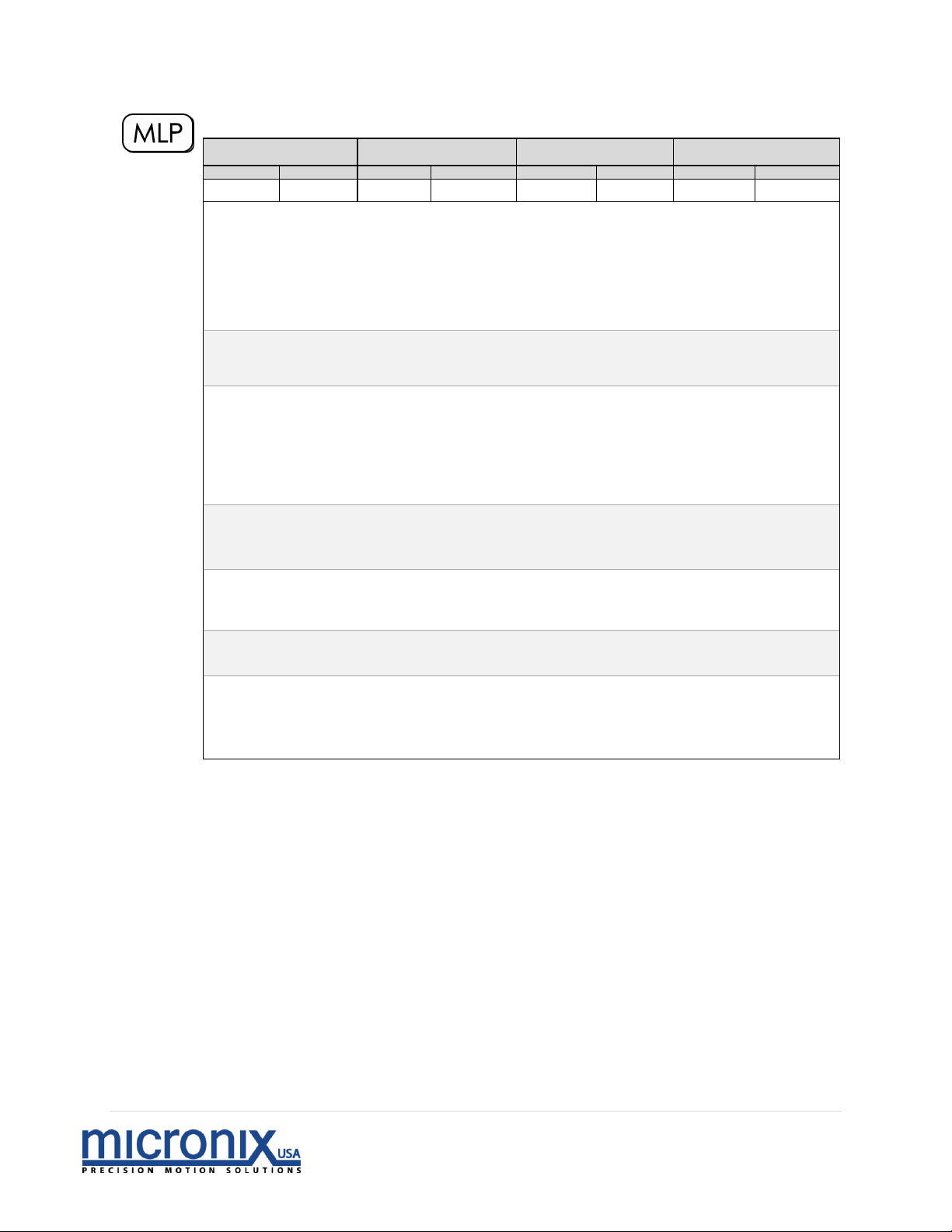
Move to Positive Limit
During Motion
Real-time
Program
Global
Set
Read
Set
Read
Set
Read
Set
Read
Command
Description:
This command initiates a move to the positive limit position.
Upon reaching the positive hard limit the controller will
then move the stage back from the hard limit and stop. If
hard stop detection using the encoder (LCG0) is active, an
error will occur if there is no encoder signal at the time of
execution.
Returns:
A read operation is not available with this command.
Syntax:
nMLP – Standard syntax
0MLP – All axes execute move to positive limit position
Error [#]:
MLP – Missing axis number [30]
Parameter
Description:
n[int] – Axis number
Parameter
Range:
n – 0 to 99
Related
Commands:
MLN, LCG
Example:
1MLP |Axis 1, Move to positive limit position
-
0MLP |All Axes, Move to positive limit position
Page 55
54 | P a g e
Rev 2.01
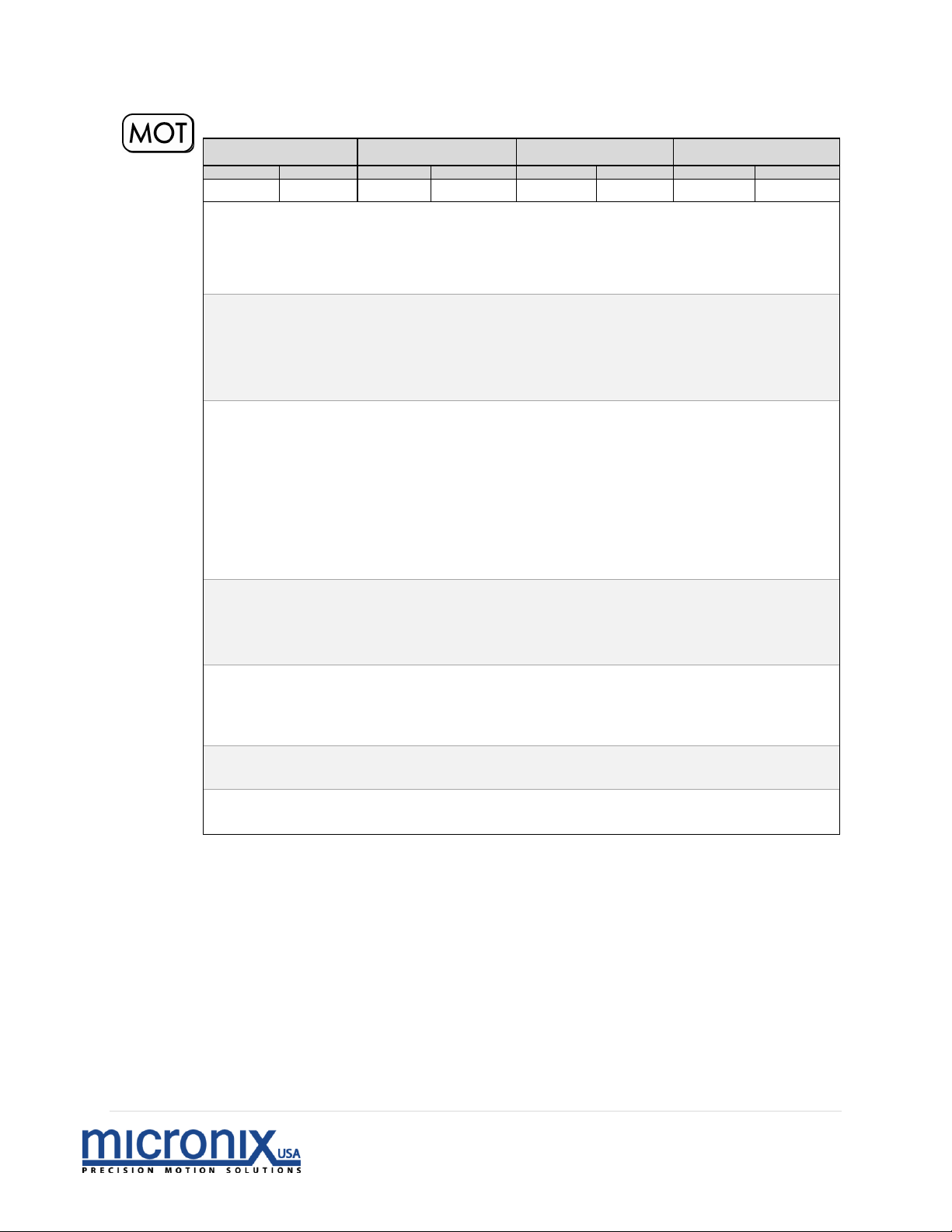
Toggle Motor Off/On
During Motion
Real-time
Program
Global
Set
Read
Set
Read
Set
Read
Set
Read
Command
Description:
This command is used to turn the motor current flow “Off”
or “On” for a specified axis. Turning the motor current off
will cause the piezo to relax and the stage will shift slightly.
Returns:
A read operation returns the following motor current off/on
values for the specified axis:
0 – Motor current is off
1 – Motor current is on
Syntax:
nMOTx – Standard syntax
nMOT? – Read motor current off/on value
0MOTx – All axes set motor value
Error [#]:
MOT? – Read operation with missing axis number [27]
xMOT – Missing motor off/on parameter [28]
Parameter
Description:
n[int] – Axis number
x[float] – Motor current off/on
? – Read motor current off/on value
Parameter
Range:
n – 0 to 99
x – 0 for motor current off
1 for motor current on
Related
Commands:
None
Example:
1MOT0 |Axis1, Set motor current to off
Page 56
55 | P a g e
Rev 2.01
Toggle Motor Polarity
During Motion
Real-time
Program
Global
Set
Read
Set
Read
Set
Read
Set
Read
Command
Description:
This command set the motor polarity for the specified axis.
If the theoretical positive direction is away from the motor,
changing this setting will make the theoretical positive
direction towards the motor.
NOTE: EPL, MPL and LDR must all be changed together to
maintain proper functionality, changing one of these values
without changing the rest will result in improper stage
behavior.
Returns:
A read operation returns the current motor polarity setting
for the specified axis.
Syntax:
nMPLx – Standard syntax
nMPL? – Read motor current off/on value
0MPLx – All axes set motor value
Error [#]:
MPL? – Read operation with missing axis number [27]
nMPL – Missing motor off/on parameter [28]
Parameter
Description:
n[int] – Axis number
x[float] – Motor Polarity setting
? – Read motor current off/on value
Parameter
Range:
n – 0 to 99
x – 0 Normal
1 Reverse
Related
Commands:
MVR
Example:
1MPL0 |Axis1, To normal Polarity
Page 57
56 | P a g e
Rev 2.01
Synchronous Move - Absolute
During Motion
Real-time
Program
Global
Set
Read
Set
Read
Set
Read
Set
Read
Command
Description:
This command is used to set up a synchronous move to an
absolute position. This command is most useful when
coordinating motion to an absolute position between 2 or
more axes and requires a RUN command on a separate line
to execute the synchronous move. An error will occur if the
commanded position is outside of the soft limits.
Returns:
A read operation is not available with this command.
Syntax:
nMSAx – Standard syntax
0MSAx – All axes execute synchronous move
Error [#]:
nMSA – Missing absolute position parameter [28]
Parameter
Description:
n[int] – Axis number
x[float] – Absolute position
Parameter
Range:
n – 0 to 99
x – -999.999999 to 999.999999 mm (degrees)
Related
Commands:
RUN, MSR
Example:
1MSA10;2MSA10 |Axis 1, Move to absolute position: 10
mm[degrees]; Axis 2, Move to absolute
position: 10 mm [degrees]
0RUN |All axes, Execute synchronous move
0MSA5 |All axes, Move to absolute position: 5
mm
[degrees]
0RUN |All axes, Execute synchronous move
Page 58
57 | P a g e
Rev 2.01
Synchronous Move – Relative
During Motion
Real-time
Program
Global
Set
Read
Set
Read
Set
Read
Set
Read
Command
Description:
This command is used to set up a synchronous move to a
position relative to the current position. This command is
most useful when coordinating relative positions between 2
or more axes and requires a RUN command on a separate
line to execute the synchronous move. An error will occur
if the commanded increment will cause the stage to travel
outside of the set soft limits.
Returns:
A read operation is not available with this command.
Syntax:
nMSRx – Standard syntax
0MSAx – All axes execute synchronous move
Error [#]:
nMSA – Missing relative position parameter [28]
Parameter
Description:
n[int] – Axis number
x[float] – Relative position
Parameter
Range:
n – 0 to 99
x – ± 0.000001 to 999.999999 mm (degrees)
Related
Commands:
RUN, MSA
Example:
4MSR.1;5MSR.5 |Axis 4, Move 0.1 mm [degrees]; Axis 5, Move
0.5 mm [degrees]
0RUN |Execute synchronous move
-
0MSR0.01 |All axes, Move 0.01 mm [degrees]
0RUN |All axes, execute synchronous move
Page 59
58 | P a g e
Rev 2.01
Move Absolute
During Motion
Real-time
Program
Global
Set
Read
Set
Read
Set
Read
Set
Read
Command
Description:
This command is used to initiate an instantaneous move to
an absolute position for a specified axis. An error will occur
if the commanded position is outside of the soft limits.
Returns:
A read operation is not available with this command.
Syntax:
nMVAx – Standard syntax
0MVAx – All axes execute instantaneous move
Error(s):
nMVA – Missing absolute position parameter [28]
Parameter
Description:
n[int] – Axis number
x[float] – Absolute position
Parameter
Range:
n – 0 to 99
x – -999.999999 to +999.999999 mm (degrees)
Related
Commands:
MVR, WFS
Example:
4MVA14.5 |Axis 4, Move to absolute position: 14.5 mm [degrees]
-
0MVA5.5 |All axes, Move to absolute position: 5.5 mm
[degrees]
Page 60
59 | P a g e
Rev 2.01
Move Relative
During Motion
Real-time
Program
Global
Set
Read
Set
Read
Set
Read
Set
Read
Command
Description:
This command is used to initiate an instantaneous move to a
relative position for a specified axis. An error will occur if
the commanded increment will cause the stage to travel
outside of the set soft limits.
Returns:
A read operation is not available with this command.
Syntax:
nMVRx – Standard syntax
0MVRx – All axes execute command.
Error(s):
nMVR – Missing relative position parameter [28]
Parameter
Description:
n[int] – Axis number
x[float] – Relative position
Parameter
Range:
n – 0 to 99
x – ± 0.000001 to ± 999.999999 mm [degrees]
Related
Commands:
MVR, WFS
Example:
6MVR10 |Axis 6, Move 10 mm [degrees]
-
0MVR.89 |All axes, Move 0.89 mm [degrees]
Page 61
60 | P a g e
Rev 2.01
Loop Program
During Motion
Real-time
Program
Global
Set
Read
Set
Read
Set
Read
Set
Read
Command
Description:
This command is used to change the number of times a
program will execute. If the program loop setting is 0, any
program that is executed will run in a continuous loop. It
can be combined with the PGS command to run a program
continuously on startup. To disable program looping, set
PGL to 1. A looping program can be stopped at any time by
sending the STP or EST commands.
This version of the command available in firmware version
1.4.53 and up. Prior versions have an on/off PGL setting
1/0.
Returns:
A read operation returns the program loop setting for the
specified axis.
Syntax:
nPGLx – Standard syntax
Error(s):
PGLx – Missing axis number [30]
nPGL – Missing program number parameter [28]
Parameter
Description:
n[int] – Axis number
x[int] – loop flag parameter
Parameter
Range:
n – 1 to 99
x – 0 – Loop indefinitely
1 – Don’t Loop
2 to 999999 – number of times an executed command will repeated
Related
Commands:
PGS, STP
Example:
1PGL0 |Axis 1, Run program 1 continuously
1PGL5 |Axis 1, Run program 5 times
Page 62
61 | P a g e
Rev 2.01
Begin Program Recording
During Motion
Real-time
Program
Global
Set
Read
Set
Read
Set
Read
Set
Read
Command
Description:
This command is used to enter program recording mode for
a specified axis. The program being recorded must use a
unique program number or else the program will be ignored.
Us the PGM? command to check program number
availability and use the ERA command to erase any
previously recorded programs. Each program has a size
limit of 4Kb.
Returns:
A read operation in not available for this command
Syntax:
nPGMx – Standard syntax
nPGM? – Read a binary representation of written program numbers
If programs 1 and 2 are written it will return 3
If programs 1 and 4 are written it will return 9
If only program 1 is written it will return 1
If only program 3 is written it will return 4
Error(s):
PGMx – Missing axis number [30]
nPGM – Missing program number parameter [28]
Parameter
Description:
n[int] – Axis number
x[int] – Program number to be recorded
Parameter
Range:
n – 1 to 99
x – 1 to 16
Related
Commands:
END, EXC, LST, ERA
Example:
1PGM3 |Axis 1, Begin recording program. Save program
as program 3
Page 63
62 | P a g e
Rev 2.01
Run Program At Start-Up
During Motion
Real-time
Program
Global
Set
Read
Set
Read
Set
Read
Set
Read
Command
Description:
This command is used to set a program to run immediately
on start-up. Only one program per axis can run on start up.
Returns:
A read operation returns a value for the specified axis in the
format below:
0 – No program set to run
1-16 – Program set to run on start-up
Syntax:
nPGSx – Standard syntax
0PGSx – Missing axis number, all axes set program to run on start-up
nPGS? – Read program(s) set to run on start-up
Error [#]:
PGS? – Read operation with missing axis number [27]
nPGS – Missing program set to run on start-up parameter
[28]
Parameter
Description:
n[int] – Axis number
x[float] – Program set to run on start-up
? – Return number of program set to run on startup.
Parameter
Range:
n – 0 to 99
x – 0 - No program
1 to 16- Specific program set to run on start-up
Related
Commands:
LST, PGM
Example:
6PGS5 | Axis 6, set program 5 to run on start-up
–
0PGS16 | All axes, set program 16 to run on start-up
–
3PGS? | Axis 3, Read program to run on start-up
–
3PGS0 | Axis 3, Set no program to run on start-up
Page 64
63 | P a g e
Rev 2.01
Set Feedback Constants
During Motion
Real-time
Program
Global
Set
Read
Set
Read
Set
Read
Set
Read
Command
Description:
This command is used to set the encoder feedback gain
constants for a specified controller.
Returns:
A read operation returns the encoder feedback constant
values for the specified axis.
Syntax:
nPIDx1,x2,x3 – Standard syntax
nPID? – Read encoder feedback constant values
Error(s):
PIDx1,x2,x3 – Missing axis number [30]
PID? – Read operation with missing axis number [27]
nPID – Missing encoder feedback constant parameters
[28]
Parameter
Description:
n[int] – Axis number
x1[float] – K
p
(proportional constant)
x2[float] – K
i
(integral constant, stepper only)
x3 [float] – K
d
(derivative constant, stepper only)
? – Read encoder feedback constants and values
Parameter
Range:
n – 1 to 99
x1 – 0.000 to 2.000
x2 – 0.000 to 2.000
x3 – 0.000 to 2.000
Related
Commands:
FBK, ENC, POS
Example:
5PID.02,.04,.05 |Axis 5, Set encoder feedback constants
to 0.02, 0.04 and 0.05, respectively
-
2PID.03,, |Axis 2, Set encoder feedback constant
Kp to 0.03, other constants remain unchanged
-
4PID,,.07 |Axis 4, Set encoder feedback constant
Kd to 0.07, other constants remain unchanged
Page 65
64 | P a g e
Rev 2.01
Position
During Motion
Real-time
Program
Global
Set
Read
Set
Read
Set
Read
Set
Read
Command
Description:
This command is used to read the position information from
the specified axis controller
Returns:
A read operation returns the position values in mm for the
specified axis in the following format:
[Theoretical position in mm, Encoder position in mm]
[Theoretical position in degrees, Encoder position in degrees]
Syntax:
nPOS? – Standard syntax
Error(s):
POS? – Read operation with missing axis number [27]
Parameter
Description:
n[int] – Axis number
? – Read position values
Parameter
Range:
n – 1 to 99
Related
Commands:
MVR
Example:
4POS? | Axis 4, Read position values
Page 66
65 | P a g e
Rev 2.01
Set Resolution
During Motion
Real-time
Program
Global
Set
Read
Set
Read
Set
Read
Set
Read
Command
Description:
This command is used to set the DAC (digital to analog
converter) steps per micron resolution for the specified axis.
Returns:
A read operation returns the resolution value in steps per
micron for the specified axis.
Syntax:
nREZx – Standard syntax
nREZ? – Read steps per micron resolution value
Error(s):
REZ? – Read operation with missing axis number [27]
REZx – Missing axis number [30]
nREZ – Missing steps per micron resolution parameter [28]
Parameter
Description:
n[int] – Axis number
x[float] – Steps per micron resolution (steps/mili-degrees) (default is 8,000)
? – Read steps per micron resolution value (steps/milli-degrees)
Parameter
Range:
n – 1 to 99
x – 0 to 999999 DAC steps per micron (steps/milli-degrees)
Related
Commands:
None
Example:
9REZ25 | Axis 9, Set resolution to 25 steps/micron
[steps/milli-degrees]
-
3REZ? | Axis 3, Read steps/micron [steps/degrees]
resolution value
Page 67
66 | P a g e
Rev 2.01
Perform Soft Reset
During Motion
Real-time
Program
Global
Set
Read
Set
Read
Set
Read
Set
Read
Command
Description:
This command is used to perform a soft reset of the
specified axis. Unsaved settings will be lost. In a multi axis
stack, if only one axis is restarted using this command and
ANR is set to 0, that axis will address as “1”, even if
another axis is already addressed as “1” causing an axis to
become unresponsive. To correct this, restart all axes.
Returns:
A read operation cannot be used with this command.
Syntax:
nRST – Standard syntax
0RST – All axes execute soft reset
Parameter
Description:
n[int] – Axis number
Parameter
Range:
n – 1 to 99
Related
Commands:
None
Example:
8RST | Axis 8, execute soft reset
Page 68
67 | P a g e
Rev 2.01
Start Synchronous Move
During Motion
Real-time
Program
Global
Set
Read
Set
Read
Set
Read
Set
Read
Command
Description:
This command is used to start a global synchronous move
previously set up by using the MSA or MSR commands.
Returns:
A read operation cannot be used with this command.
Syntax:
RUN – Standard syntax
Parameter
Description:
-
Parameter
Range:
-
Related
Commands:
MSA, MSR
Example:
3MSR5;4MSR5 | Axis 3, setup 5 mm[degrees] move;
Axis 4, setup 5 mm [degrees] move
0RUN | All axes, Execute synchronous moves
Page 69
68 | P a g e
Rev 2.01
Save Axis Settings
During Motion
Real-time
Program
Global
Set
Read
Set
Read
Set
Read
Set
Read
Command
Description:
This command is used to save all settings for the specified
axis. This allows an axis to be configured on power up.
Returns:
A read operation cannot be used with this command.
Syntax:
nSAV – Standard syntax
0SAV – All axes save settings
Parameter
Description:
n[int] – Axis number
Parameter
Range:
n – 0 to 99
Related
Commands:
None
Example:
16SAV | Axis 16, save settings
Page 70
69 | P a g e
Rev 2.01
Status Byte
During Motion
Real-time
Program
Global
Set
Read
Set
Read
Set
Read
Set
Read
Command
Description:
This command is used to check the status register for a specified
axis.
Returns:
A read operation will return an integer from 0 to 255 describing
the status of the axis. The byte must be decoded in binary to
determine the value of each bit.
Bit 7 6 5 4 3 2 1 0
Name
ERR
ACC
CNST
DEC
STP
PGM
PLS
NLS
Note: Bits 2, 1 and 0 are unused
Bit 7: 1 – One or more errors have occurred. Use ERR? Or CER to
clear.
0 – No Errors have occurred.
Bit 6: 1 – Currently in Acceleration phase of motion.
0 – Not in Acceleration phase of motion.
Bit 5: 1 – Currently in Constant Velocity phase of motion.
0 – Not in Constant Velocity phase of motion.
Bit 4: 1 – Currently in Deceleration phase of motion.
0 – Not in Deceleration phase of motion.
Bit 3: 1 – Stage has stopped. (In Closed Loop Stage, is in the deadband)
0 – Stage is moving. (In Closed Loop, Stage is out of deadband)
Bit 2: 1 – A Program is currently running
0 – No program is running
Bit 1: 1 – Positive Switch is Activated
0 – Positive Switch is not Activated
Bit 0: 1 – Negative Switch is Activated
0 – Negative Switch is not Activated
Syntax:
nSTA? – Standard syntax
Error(s):
STA? – Read operation with missing axis number [27]
nSTA – Missing read operation parameter [28]
Parameter
Description:
n[int] – Axis number
? – Read status register
Parameter
Range:
n – 1 to 99
Related
Commands:
None
Example:
6STA? | Axis 6, Read status register
Page 71
70 | P a g e
Rev 2.01
Stop Motion
During Motion
Real-time
Program
Global
Set
Read
Set
Read
Set
Read
Set
Read
Command
Description:
This command is used to stop motion for a specified axis.
Returns:
A read operation cannot be used with this command.
Syntax:
nSTP – Standard syntax
0STP – All axes execute stop
Parameter
Description:
n[int] – Axis number
Parameter
Range:
n – 0 to 99
Related
Commands:
EST, DEC
Example:
8STP | Axis 8, execute stop
Page 72
71 | P a g e
Rev 2.01
Save Startup Position
During Motion
Real-time
Program
Global
Set
Read
Set
Read
Set
Read
Set
Read
Command
Description:
This command is used to set the startup position. Default is
0. This setting does not require the SAV command to save it
into memory. It also does not change with a DEF command.
To reset the Startup position to the default, send nSVP0.
Returns:
A read operation returns the Startup position setting for the
specified axis.
Syntax:
nSVP – Standard syntax
0SVP – Missing axis number, command accepted as standard
syntax
Parameter
Description:
n[int] – Axis number
x[float] – Startup Position mm
? – Read Startup Position
Parameter
Range:
n – 0 to 99
x – TLN (-999.999999mm) to TLP(999.999999mm)
Related
Commands:
None
Example:
4SVP | Set current position to Startup position
2SVP2.3 | Set startup position to 2.3mm
Page 73
72 | P a g e
Rev 2.01
Sync
During Motion
Real-time
Program
Global
Set
Read
Set
Read
Set
Read
Set
Read
Command
Description:
This command is used in a program together with the wait
for sync [WSY] command in order to synchronize motion
between multiple axes.
Returns:
A read operation cannot be used with this command.
Syntax:
nSYN – Standard syntax
0SYN – Missing axis number, command accepted as standard
syntax
Parameter
Description:
n[int] – Axis number
Parameter
Range:
n – 0 to 99
Related
Commands:
WSY
Example:
4SYN | Send sync to axis 4
Page 74
73 | P a g e
Rev 2.01
Negative Soft Limit Position
During Motion
Real-time
Program
Global
Set
Read
Set
Read
Set
Read
Set
Read
Command
Description:
This command is used to set the desired negative soft limit
position, using absolute position, for the specified axis. The
negative soft limit position value must be less than the
positive soft limit position value [TLP] for the command to
be accepted.
Returns:
A read operation returns the negative soft limit position
value.
Syntax:
nTLNx – Standard syntax
nTLN? – Read negative soft limit position value
0TLNx – All axes set limit position value
nTLN – Set current position to negative limit
Error(s):
TLN? – Read operation with missing axis number [27]
Parameter
Description:
n[int] – Axis number
x[float] – Negative soft limit position
? – Read negative soft limit position
Parameter
Range:
n – 0 to 99
x – -999.999999 to TLP mm [degrees]
Related
Commands:
TLP
Example:
2TLN0.005 | Axis 2, Set negative soft limit position
to 0.005 mm [degrees]
-
6TLN? | Axis 6, Read negative soft limit position
value
-
1TLN | Axis 1 Set the negative limit to the current
position
Page 75
74 | P a g e
Rev 2.01
Positive Soft limit Position
During Motion
Real-time
Program
Global
Set
Read
Set
Read
Set
Read
Set
Read
Command
Description:
This command is used to set the desired positive soft limit
position, using absolute position, for the specified axis. The
positive soft limit position value must be greater than the
negative soft limit position value [TLN] for the command to
be accepted.
Returns:
A read operation returns the positive soft limit position
value for the specified axis.
Syntax:
nTLPx – Standard syntax
nTLP? – Read positive soft limit position value
0TLPx – All axes set limit position value
nTLN – Set current position to negative limit
Error(s):
TLP? – Read operation with missing axis number [27]
Parameter
Description:
n[int] – Axis number
x[float] – Positive soft limit position
? – Read positive soft limit position
Parameter
Range:
n – 0 to 99
x – TLN to + 999.999999 mm [degrees]
Related
Commands:
TLN
Example:
4TLP10.005 | Axis 2, Set positive soft limit
position to 10.005 mm [degrees]
-
9TLP? | Axis 9, Read positive soft limit position
value
-
1TLP | Axis 1 Set the positive limit to the current
position
Page 76
75 | P a g e
Rev 2.01
Perform Trace
During Motion
Real-time
Program
Global
Set
Read
Set
Read
Set
Read
Set
Read
Command
Description:
This command is used to execute a trace of the specified
axis. In lieu of the trace beginning at value stored in x3, a
TTL logic pulse to an IO pin [IOF] [IOD] can be used to
trigger the trace function from an external source.
Returns:
A read operation returns the position samples taken for the
specified axis.
Syntax:
nTRAx1,x2,x3 – Standard syntax
nTRA? – Read position values
0TLPx1,x2,x3 – All axes execute trace
Error(s):
TRA? – Read operation with missing axis number [27]
nTRA – Missing parameters [28]
Parameter
Description:
n[int] – Axis number
x1[int] – Number of samples taken (default is 1000)
x2[int] – 10kHz /Sampling frequency (default is 1)
x3[float] – Trace starting position (default is immediate)
? – Read number of position samples collected
Parameter
Range:
n – 0 to 99
x1 – 1 to 9000
x2 – 1 to 1000 Servo clocks per cycle
x3 – 000.000001 to 999.999999 mm [degrees]
Related
Commands:
DAT, IOF, IOD
Example:
5TRA5,10,1 | Axis 5, execute trace with 5
samples at a sampling frequency of 1kHz starting
at a position of 1 mm [degrees]
3TRA2000,, | Axis 3, execute trace with
2000 samples at a sampling frequency of 10kHz
starting at the current position
Page 77
76 | P a g e
Rev 2.01
Velocity
During Motion
Real-time
Program
Global
Set
Read
Set
Read
Set
Read
Set
Read
Command
Description:
This command is used to set the desired velocity for the
specified axis. The velocity may be changed on-the-fly by
sending another VEL command during motion. The
velocity value should be lower than the maximum allowable
velocity [VMX] for the command to be accepted.
Returns:
A read operation returns the velocity value in mm/s for the
specified axis.
Syntax:
nVELx – Standard syntax
nVEL? – Read velocity value
0VELx – Missing axis number, all axes set velocity
Error [#]:
VEL? – Read operation with missing axis number [27]
nVEL – Missing velocity parameter [28]
Parameter
Description:
n[int] – Axis number
x[float] – Velocity value
? – Read velocity value
Parameter
Range:
n – 0 to 99
x – 000.001 to VMX (999.999 mm/s) [degrees/s]
Related
Commands:
VMX, REZ
Example:
1VEL.25 |Axis 1, Set velocity to 0.25mm/s [degrees/s]
-
5VEL? |Axis 5, Read velocity value
Page 78
77 | P a g e
Rev 2.01
Firmware Version
During Motion
Real-time
Program
Global
Set
Read
Set
Read
Set
Read
Set
Read
Command
Description:
This command is used to check the firmware version for the
specified axis.
Returns:
A read operation returns the firmware version for the
specified axis.
Syntax:
nVER? – Standard syntax
Error(s):
VER? – Read operation with missing axis number [27]
nVER – Missing read operation parameter [28]
Parameter
Description:
n[int] – Axis number
? – Read firmware version
Parameter
Range:
n – 1 to 99
Related
Commands:
None
Example:
11VER? | Axis 11, Read firmware version
Page 79
78 | P a g e
Rev 2.01
Maximum Allowable Velocity
During Motion
Real-time
Program
Global
Set
Read
Set
Read
Set
Read
Set
Read
Command
Description:
This command is used to read the maximum allowable
velocity for a specific axis. This value is calculated based on
the steps per micron parameter in the REZ command.
Returns:
A read operation returns the maximum allowable velocity
value in mm/s for the specified axis.
Syntax:
nVMX? – Read maximum allowable velocity value
Error [#]:
VMX? – Read operation with missing axis number [27]
nVMX – Missing read operation parameter [123]
Parameter
Description:
n[int] – Axis number
? – Read maximum allowable velocity value
Parameter
Range:
n – 1 to 99
Related
Commands:
REZ, VEL
Example:
4VMX? |Axis 4, Read maximum allowable
velocity value
Page 80
79 | P a g e
Rev 2.01
Encoder Velocity
During Motion
Real-time
Program
Global
Set
Read
Set
Read
Set
Read
Set
Read
Command
Description:
This command returns the actual velocity calculated from
the encoder.
Returns:
A read operation returns the encoder velocity in mm/s.
Syntax:
nVRT? – Standard syntax
Error [#]:
VRT? – Read operation with missing axis number [27]
Parameter
Description:
n[int] – Axis number
Parameter
Range:
n – 1 to 99
Related
Commands:
POS
Example:
5VRT? |Axis 5, Read encoder velocity
Page 81
80 | P a g e
Rev 2.01
Wait For Stop
During Motion
Real-time
Program
Global
Set
Read
Set
Read
Set
Read
Set
Read
Command
Description:
This command is used in a program to wait until motion is
completed to begin executing the next command.
Returns:
A read operation cannot be used with this command.
Syntax:
nWST – Standard syntax
WST – Missing axis number, command accepted as standard
syntax
Parameter
Description:
n[int] – Axis number
Parameter
Range:
n – 1 to 99
Related
Commands:
PGM
Example:
7WST | Axis 7, Wait for motion to stop before
executing next command
Page 82
81 | P a g e
Rev 2.01
Wait For Sync
During Motion
Real-time
Program
Global
Set
Read
Set
Read
Set
Read
Set
Read
Command
Description:
This command is used in a program together with the sync
[SYN] command in order to synchronize motion between
multiple axes.
Returns:
A read operation cannot be used with this command.
Syntax:
nWSY – Standard syntax
WSY – Missing axis number, command accepted as standard
syntax
Parameter
Description:
n[int] – Axis number
Parameter
Range:
n – 1 to 99
Related
Commands:
SYN
Example:
1WSY | Axis 1, Wait until sync command is
received before executing next
command
Page 83
82 | P a g e
Rev 2.01
Wait For Time Period
During Motion
Real-time
Program
Global
Set
Read
Set
Read
Set
Read
Set
Read
Command
Description:
This command is used in a program to wait for a specified
period of time before executing the next command.
Returns:
A read operation cannot be used with this command.
Syntax:
nWTMx – Standard syntax
WSTx – Missing axis number, command accepted as standard
syntax
Parameter
Description:
n[int] – Axis number
x[int] – Time
Parameter
Range:
n – 1 to 99
x – 0 to 999999 milliseconds
Related
Commands:
PGM
Example:
2WTM42 | Axis 2, Wait for 42 milliseconds before
executing next command
Page 84
83 | P a g e
Rev 2.01
Zero Position
During Motion
Real-time
Program
Global
Set
Read
Set
Read
Set
Read
Set
Read
Command
Description:
This command is used to set the absolute zero position for
the specified axis.
Returns:
A read operation cannot be used with this command.
Syntax:
nZRO – Standard syntax
Error [#]:
ZRO – Missing axis number [123]
Parameter
Description:
n[int] – Axis number
Parameter
Range:
n – 1 to 99
Related
Commands:
None
Example:
1ZRO | Axis 1, set current position as absolute zero
Page 85
84 | P a g e
Rev 2.01
Error Messages
Error
Number
Name
Description
10
Receive Buffer Overrun
The Receive Buffer has reached or exceeded
maximum capacity.
11
Motor Disabled
The command that triggered this error was trying to
move the servo while it was disabled.
12
No Encoder Detected
The command that triggered this error was trying to
access encoder data when no encoder was
attached.
13
Index Not Found
The controller moved across the full range of motion
and did not find an index.
14
Home Requires Encoder
The HOM command requires an encoder signal.
15
Move Limit Requires
Encoder
The MLN and MLP commands require an encoder
signal.
20
Command is Read Only
The command that triggered this error only supports
read operations. The command must be followed by
a question mark to be accepted. Ex: XXX?
21
One Read Operation Per
Line
Multiple read operations on the same command line.
Only one read operation is allowed per line, even if
addressed to separate axes.
22
Too Many Commands On
Line
The maximum number of allowed commands per
command line has been exceeded. No more than 8
commands are allowed on a single command line.
23
Line Character Limit
Exceeded
The maximum number of characters per command
line has been exceeded. Each line has an 80
character limit.
24
Missing Axis Number
The controller could not find an axis number or the
beginning of an instruction. Check the beginning of
the command for erroneous characters.
25
Malformed Command
The controller could not find a 3-letter instruction in the
input. Check to ensure that each instruction in the line
has exactly 3 letters referring to a command.
Page 86
85 | P a g e
Rev 2.01
26
Invalid Command
The 3-letter instruction entered is not a valid
command. Ensure that the 3-letter instruction is a
recognizable command.
27
Global Read Operation
Request
A read request for a command was entered without
an axis number. A read request cannot be used in a
global context.
28
Invalid Parameter Type
1. The parameter entered does not correspond to the
type of number that the instruction requires. For
example, the command may expect an integer
value, therefore sending a floating point value will
trigger this error.
2. The allowable precision for a parameter has been
exceeded. For example, velocity can be specified
with a precision of 0.001 mm/sec. If a more precise
velocity value of 0.0001 mm/sec is entered, this error
will be triggered.
Refer to the command pages for the type of
parameter that each command expects.
29
Invalid Character in
Parameter
There is an alpha character in a parameter that
should be a numeric character.
30
Command Cannot Be
Used In Global Context
The command entered must be addressed to a
specific axis number. Not all commands can be used
in a global context. Check the specific command
page or the table of commands for more info.
31
Parameter Out Of Bounds
The parameter is out of bounds. The current state of
the controller will not allow this parameter to be used.
Check the command page for more information.
32
Incorrect Jog Velocity
Request
The jog velocity can only be changed during motion
by using a new JOG command. If the VEL command
is used to change the velocity, this error will be
triggered. The VEL command can only be used to
change velocity during motion initiated by the move
commands [MVR, MVA, MSR, MSA].
33
Not In Jog Mode
Sending a JOG command during motion initiated by
a move command will trigger this error. To initiate Jog
Mode, the controller should be at stand-still. To
change velocity during a move, use the VEL
command.
34
Trace Already In Progress
This error is triggered when a new trace command is
received after a trace is already in progress. Trace
settings may be modified only if the trace hasn’t
started recording data. Otherwise, wait until the trace
has finished before modifying the trace settings.
35
Trace Did Not Complete
An error occurred while recording trace data. Try the
operation again.
Page 87
86 | P a g e
Rev 2.01
36
Command Cannot Be
Executed During Motion
Only certain commands can be executed when
motion is in progress. Check the command pages for
information on individual commands.
37
Move Outside Soft Limits
If a requested move will take the controller outside of
the preset travel limits, then the command will not be
executed.
38
Read Not Available For
This Command
This error is triggered by a read request from a
command that does not support a read operation.
39
Program Number Out of
Range
The number entered for the program number was
either less than 1 or greater than 16.
40
Program Size Limit
Exceeded
The program has exceeded the character limit of 4
Kb.
41
Program failed to Record
Error in recording program. Erase program and try
operation again.
42
End Command Must Be
on its Own Line
The End command used to end a program must be
on a separate line from all other instructions.
43
Failed to Read Program
An error occurred while trying to read a program. Try
the Operation again.
44
Command Only Valid
Within Program
The command that triggered this error is only suitable
for use within a program.
45
Program Already Exists
A program already exists for the indicated program
parameter. The program must be erased with the ERA
command before being written again.
46
Program Doesn’t Exist
The indicated program does not exist. This error can
occur when you try to execute a program number
that has not had a program assigned to it.
47
Read Operations Not
Allowed Inside Program
Read Operations are not permitted in programs.
48
Command Not Allowed
While Program in Progress
The command that triggered this error was given while
a program was executing.
50
Limit Activated
Motion in the direction of the activated limit switch is
disallowed if limit switches are enabled.
Page 88
87 | P a g e
Rev 2.01
51
End of Travel Limit
The requested move will take the controller outside of
its valid travel range, therefore the move is disallowed.
52
Home In Progress
A Home or a Move To Limit Procedure is in progress.
Motion commands are disallowed during this time. A
STP or EST command can be used to terminate the
Home, and then a motion command can be sent.
53
IO Function Already In
Use
The I/O Function in question is already assigned to
another I/O pin. Some Functions can only be
assigned to one pin at a time. See the
documentation for each function for more details.
55
Limits Are Not Configured
Properly
Both Limit Switches are active, so motion is disallowed
in both directions. Most likely the LPL (Limit Polarity
command) setting should be switched.
80
Command Not Available
in this Version
The command entered is not supported in this version
of the firmware.
81
Analog Encoder Not
Available In this Version
The current version of firmware installed does not
support Analog Encoders.
Page 89
88 | P a g e
Rev 2.01
8. Pin Outs
8.1.1 Power Pin-Out
Pin
Description
1
+24V
2
GND
8.1.2 Motor/Encoder Pin-Out
Pin
Description
1
Motor Phase 1
2
Motor Phase 2
3
N/C
4
N/C
5
Motor GND
6
Limit Switch +
7
Limit Switch -
8
A+ 9 B+
10
Index+
11
+5V
12
Signal GND
13
A-
14
B-
15
Index-
8.1.3 RS-485 Input
Pin
Description
1
+24VDC
2
24V GND
3
RS485 A
4
RS485 B
5
ID In
6
RS485 GND
8.1.4 RS-485 Output
Pin
Description
1
+24VDC
2
24V GND
3
RS485 A
4
RS485 B
5
ID Out
6
RS485 GND
Page 90

89 | P a g e
Rev 2.01
 Loading...