

Page 1

iPen User’s Manual Version 1.1.1 Date: July/2006
Micro-Nits Co., Ltd. Page: 1/24
Room 212, #40, Rd HsiehFu, Hsinchu, Taiwan, ROC
Micro-Nits Virtual Electronic White Board
User Manual
Page 2

iPen User’s Manual Micro- Nits Co. LTD
Version 1.1.1 Date: July/2006 Page: 2 of 24
Table of Content
Table List, Figure List……………………………………………………………………………….P4
1. Introduction
1.1 Packing list ………………………………………………………………………………P.4
1.2 Function buttons …………………………………………………………………………P.5
1.3 System Requirements …………………………………………………………………..P.6
1.4 System Spec ……………………………………………………………………………..P.6
2. Installation
2.1 First time installation:
2.1.1 Installation procedures ……………………………………………………………P8
2.1.2 Installed components ……………………………………………………………..P.11
2.2 H/W connection, Re-connection ………………………………………………………..P.11
3. Application
3.1 User Interfaces ……………………………………………………………………………P.12
3.2 Alignment Set up …………………………………………………………………………P.12
3.3 Auto mode ………………………………………………………………………………...P.16
4. User Tips
4.1 During setup ……………………………………………………………………………P.17
4.2 During writing …………………………………………………………………………..P.18
5. Trouble Shooting
5.1 Is the H/W connection OK? …………………………………………………………….P.20
5.2 Is the S/W installation OK? …………………………………………………………….P.20
5.3 Is the alignment OK? ……………………………………………………………………P.20
5.4 No Capture Device? ……………………………………………………………….……P.20
5.5 Is your initialized parameter OK? ………………………………………………..…….P.20
5.6 What if I do not see the alignment square nuts? ……………………………..………P.20
6. Warranty ………..……………………………………………………………………………..P.21
Micro-Nits Co. Ltd. Has the right to change the content without any notice to customers.
Page 3

iPen User’s Manual Micro- Nits Co. LTD
Version 1.1.1 Date: July/2006 Page: 3 of 24
List of Table
Table 1: Wireless hand hold device function key list
Table 2: Optimized operation distance from image screen to sensor
Table 3: File menu listed selection item.
Table 4: Help menu selection item
List of Figures
Figure 01: Sensor base picture
Figure 02: Wireless handhold device picture
Figure 03: Sensor driver installation request
Figure 04: Sensor driver files copied
Figure 05: Sensor driver installation completion
Figure 06: iPen application main menu
Figure 07: Optional menu & Help menu
Figure 08: Auto alignment screen
Figure 09: Sensor code
Figure 10: Sensor code input
Figure 11: Alignment accuracy information
Figure 12: Readme.txt
Figure 13: Icons or balloons might impact on alignment performance
Figure 14: Screen key board
Figure 15: Asian Font hand writing input pad
Figure 16: Drawing pad for annotation to any Office 2003 application.
Page 4
iPen User’s Manual Micro- Nits Co. LTD
Version 1.1.1 Date: July/2006 Page: 4 of 24
1.
Introduction
1. The Micro-Nits Virtual Electronic White Board is an accurate and fully automated
product as the interactive tool during presentation with projected material. It is
specially designed for the modern high resolution front projector application of LCD,
LCOS or DLP technologies. The whole procedure is arranged that presenter does
not need the support of keyboard or mouse during presentation. It is very powerful
and efficient equipment for easy setup, information highlighting, word hand writing
and pointing. The setup is very easy for both S/W H/W and alignment. Please enjoy
this product while you do the presentation or in the training course.
For a complete set up, there are 4 key steps to follow:
1. S/W set up : Chapter 2 installation ( Please do not plug this device before
installation)
2. H/W connection: Chapter 2 H/W connection
3. Sensor, Projection, PC connection : Chapter 3 Application
4. Precision alignment: Chapter 3.3 automated alignment
Then the setup is completed and you can enjoy this fantastic technology.
1.1 Packing list
There are three major components
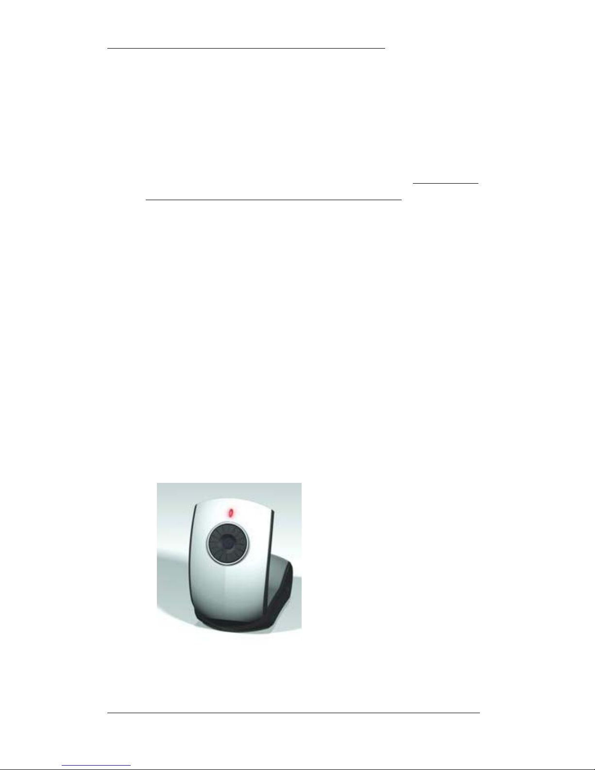
A. Area Sensor with base, Refer to Fig 01.
B. Wireless handhold Pen, refer to Fig 02.
C. Installation CD
Figure 01: Sensor base picture
Page 5
iPen User’s Manual Micro- Nits Co. LTD
Version 1.1.1 Date: July/2006 Page: 5 of 24
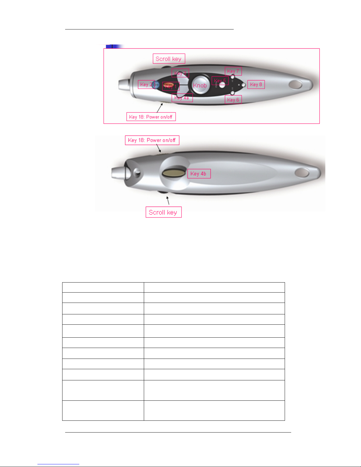
Figure 02: Wireless handhold device picture
1.2 Function buttons
Please refer to Fig 02, There are totally 11 buttons for the wireless handhold device to
fully function without the access to the key board after the H/W is setup and basic
alignment is done.
Tracking Knob Control Cursor
Key 1: laser on/off ; for remote input
Key 2: Radiation on/off; for on screen writing
Key 3: Mouse Right
Key 4a / Key4b: Mouse Left
Key 5: Menu Key
Key 6: F5 : activate auto-alignment
Key7: F11: get better preview
Key8: PrtSC
Combination Key 9: Ctrl + P ( Key 5 + key 6) :
Power point change to pen mode
Combination Key 10: Ctrl + E ( Key 5 + Key 7) :
Power point change to eraser
Page 6

iPen User’s Manual Micro- Nits Co. LTD
Version 1.1.1 Date: July/2006 Page: 6 of 24
Combination Key 11: Ctrl + A ( Key 5 + key8) :
Power point change to arrow
key 12: Scroll up
key 13: scroll pressed : Enter
key 14: scroll down
Combination key 15: Key 5 + scroll pressed ( Channel ID)
Combination key 16: Key 5 + scroll down: Alt + Tab
Combination Key17: Key 5 + Scroll up ( Wheel down)
Key 18: on/off key ;battery power
Signal
Radiation Green LED Radiation is on, press again to turn off
Laser Red LED lit Laser is on, press to turn on, release to turn off
Power key Red blink RF channel ID pairing
Power key Red lit Low batter voltage
Power key Green lit Battery power is on
Table 1: Wireless hand hold device function key list
1.3 System Requirements
The user needs a high resolution and bright projector (if projector output is higher than
1500 Lumen, please project to larger screen) and a notebook computer or desktop PC.
Due to the high technology used, there are couple requirements on the operation system
and limitation to environment.
A. Operation system: MS Windows 2000 or XP with Direct show installed
B. Operation CPU: Better than 1.0 GHz, for iPen application.
C. Operation memory required:
Better than 200 MB for iPen application.
D. One USB 2.0 port required
E. CD ROM reader for s/w installation/or USB disk
F. Keyboard for Hot Key input
F. H/D free space for installation and application running: 15 MB
G. 1.5 V 3A battery x 2 for handhold device
H. Used indoors
1.4 Optimized System Spec
Page 7

iPen User’s Manual Micro- Nits Co. LTD
Version 1.1.1 Date: July/2006 Page: 7 of 24
Projector resolution: better than 800 x 600
1.4.1 Projection image size: 50”~150”
1.4.2 Typical environment automated Alignment time: 3 sec
1.4.3 Tough environment automated alignment time: 10 sec
1.4.4 Optimized alignment accuracy within chess board area: +/- 10 pixel
1.4.5 Optimized alignment repeatability within chess board area: +/- 10 pixel
1.4.6 Full screen full scan area optimized resolution: 2000 x 1500 (Micro-Nits Lab
environment with certified projector)
1.4.7 Optimized cursor jittering: +/- 4 pixel (Micro-Nits Lab environment with
certified projector)
1.4.8 The testing environment should be on a flat and diffusive screen with perfect
keystone corrected projection image in Micro-Nits lab.
Page 8
iPen User’s Manual Micro- Nits Co. LTD
Version 1.1.1 Date: July/2006 Page: 8 of 24
2 Installation
After you read the first chapter 1 Introduction that you should understand the basic that the
iPen can support. Please check that both your computer (either Notebook or desktop PC)
and projector fulfill the requirement descriptions listed in Chapter 1.
Do not plug the USB plug into the notebook USB port before the S/W installation.
You have to plug after the s/w is installed
2.1 First time installation:
If this is the first time installation on the notebook of PC for presentation, please follow
the instruction listed in the paragraph. Please have the installation CD password number
and sensor code ready for input during s/w installation.
2.1.1 Installation procedures
Put the CD into CD reader Find the Setup.exe to execute the installation or the
CD auto run will execute this setup application.
Follow the instructions shown on the screen to install the application, drivers to the destination
disk and folder.
After the s/w installation, plug the iPen USB cable into the notebook USB 2.0 port
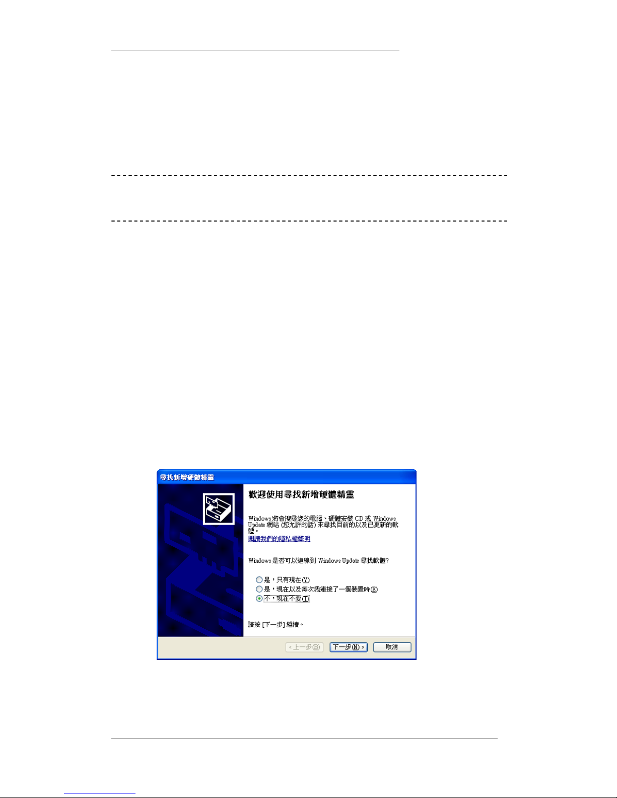
and wait the notebook to inform you that new unknown devices are connected. The
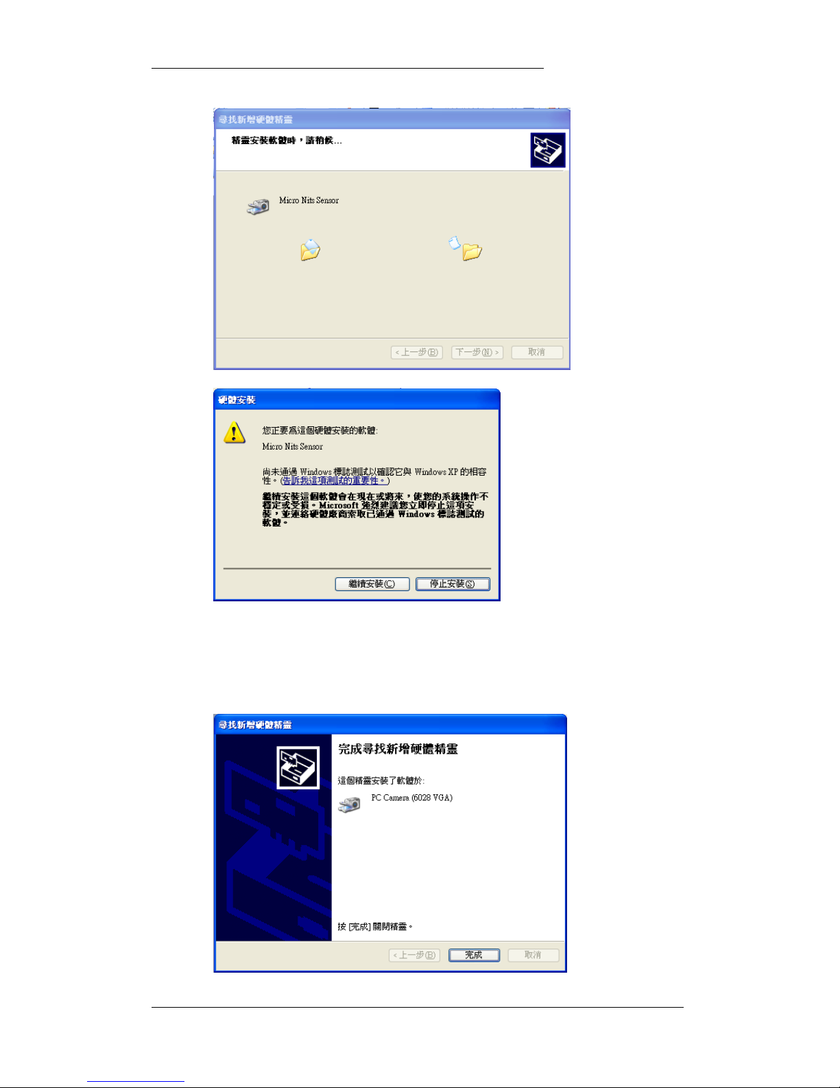
installation wizard notice will show up as Fig 03.
Figure 3. Sensor driver installation request
Page 9
iPen User’s Manual Micro- Nits Co. LTD
Version 1.1.1 Date: July/2006 Page: 9 of 24
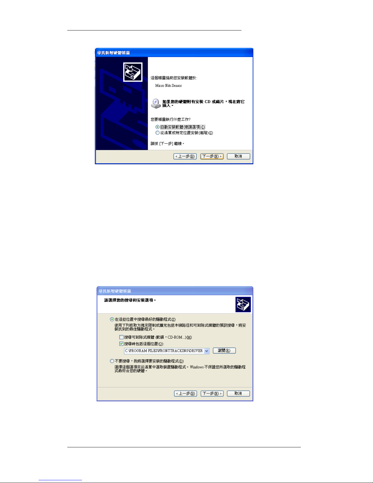
Figure 3.B Sensor driver installation request
The setup action during the installation already installed the necessary
information into the right folder, please check the first item for auto driver
selection, and let the operation system do the rest for you.
Note: Just in case if this does not work, please check the 2
nd
item of install from the
specified directory and click Next button go to next page as shown in Fig 03 C. Select item 2
to inform the system to get driver installation system the right INF file from the installation
folder. Using browser button to select the right folder, the default older is “ C:\\Program
Files\iPen\Driver”. Click next for the system to automate the driver installation procedures.
Figure 3.C Sensor driver installation request
Page 10
iPen User’s Manual Micro- Nits Co. LTD
Version 1.1.1 Date: July/2006 Page: 10 of 24
Figure 04. Sensor driver files copied
There will be another message popup as Fig 04. After couple system drivers
installed, the Completed message shows up as Fig 09. Then the system is installed
complete.
Page 11

iPen User’s Manual Micro- Nits Co. LTD
Version 1.1.1 Date: July/2006 Page: 11 of 24
Figure 05. Sensor driver installation completion
2.1.2 Installed components
There are two folders under the installation directory: Application folder and driver
folder.
The files in the application folders are:
ViewPen100.exe
uNitsc.DLL
uNits_core_codes.und
uNits_core_thres.und
uNits_core_dsize.und
uNits_core_refer.und
uNits_core_range.und
2.2 H/W re-connection.
The Windows operation system will recognize and register the port that connected with
iPen. If the connected port is changed to other port, the operation system will request to
re-install the driver again. However, due to the s/w chosen, you might be requested to
reboot your notebook or PC after the driver re-installed, this will not happen in most of the
cases. The procedure is identical as the procedures described as listed in section 2.1. After
the reinstallation, user is able to use the system.
2.3 Un-install
It is easy to un-install the files build by the setup program, please just simply click the
un-install on the Uninstall Front Tracking, then the program will automatically un-install the
folder.
Page 12

iPen User’s Manual Micro- Nits Co. LTD
Version 1.1.1 Date: July/2006 Page: 12 of 24
3. Application
The H/W setup for Micro-Nits virtual electronic whiteboard is very simple. After the
S/W is installed and H/W connected to the PC and
The steps are:
1. User just simply puts the sensor base on the table. With distance about 1.2
times the diagonal size of the projected image. Or user can put the sensor
as close as to the projector.
2. The recommended distance:
70吋 > 3 m
100吋 > 4 m
120吋 > 5 m
150吋 > 6 m
Table 2: Optimized operation distance from image screen to sensor
3. Make sure that the sensor base does not block any of the projection image.
4. Make sure the projected image is well key stone corrected to get better
alignment effect.
5. The direction is not a concern; however, the sensor should be within 30
degree solid angel from the norm of image plan center.
After the basic setup, user can click on the iPen icon to activate the application, please
refer to the following sections to learn more about the meaning of the user interfaces.
In the sections, we will describe:
3.1 User Interfaces: introduction to the user interface
3.2 Alignment set up: Description for the alignment criteria
3.3 Auto mode: description of fully automated mode
3.1 User Interfaces
What you should learn from this section is only using F5 on the keyboard or F5 on the
handhold device to activate alignment screen and automate alignment. If during alignment,
there are not enough alignment nuts, please press F11 on the key board or on the
handhold device to get clear preview effect.
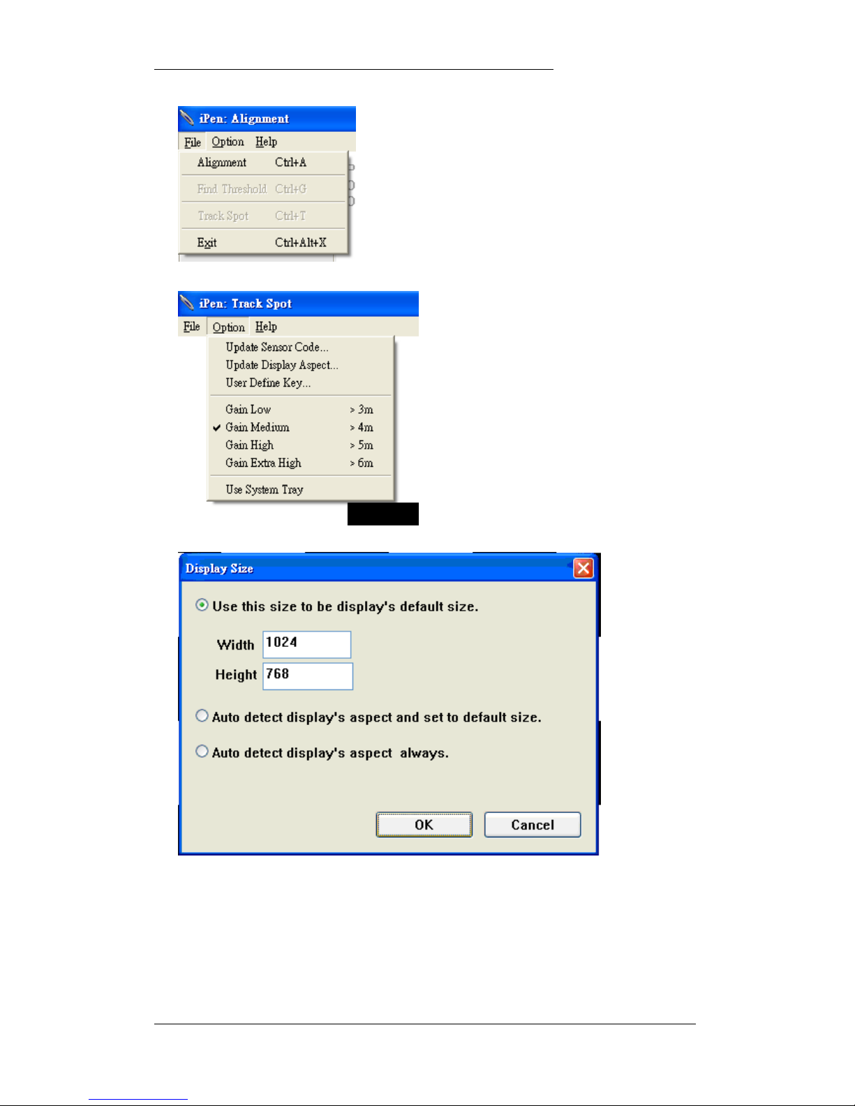
Refer to Fig 6. On the main menu bar, there are three items.
File, Option, Help.
Page 13
iPen User’s Manual Micro- Nits Co. LTD
Version 1.1.1 Date: July/2006 Page: 13 of 24
Fig 6. ViewPen application main menu
Fig 6.1 Projection Screen aspect ratio selection and setting
Page 14
iPen User’s Manual Micro- Nits Co. LTD
Version 1.1.1 Date: July/2006 Page: 14 of 24
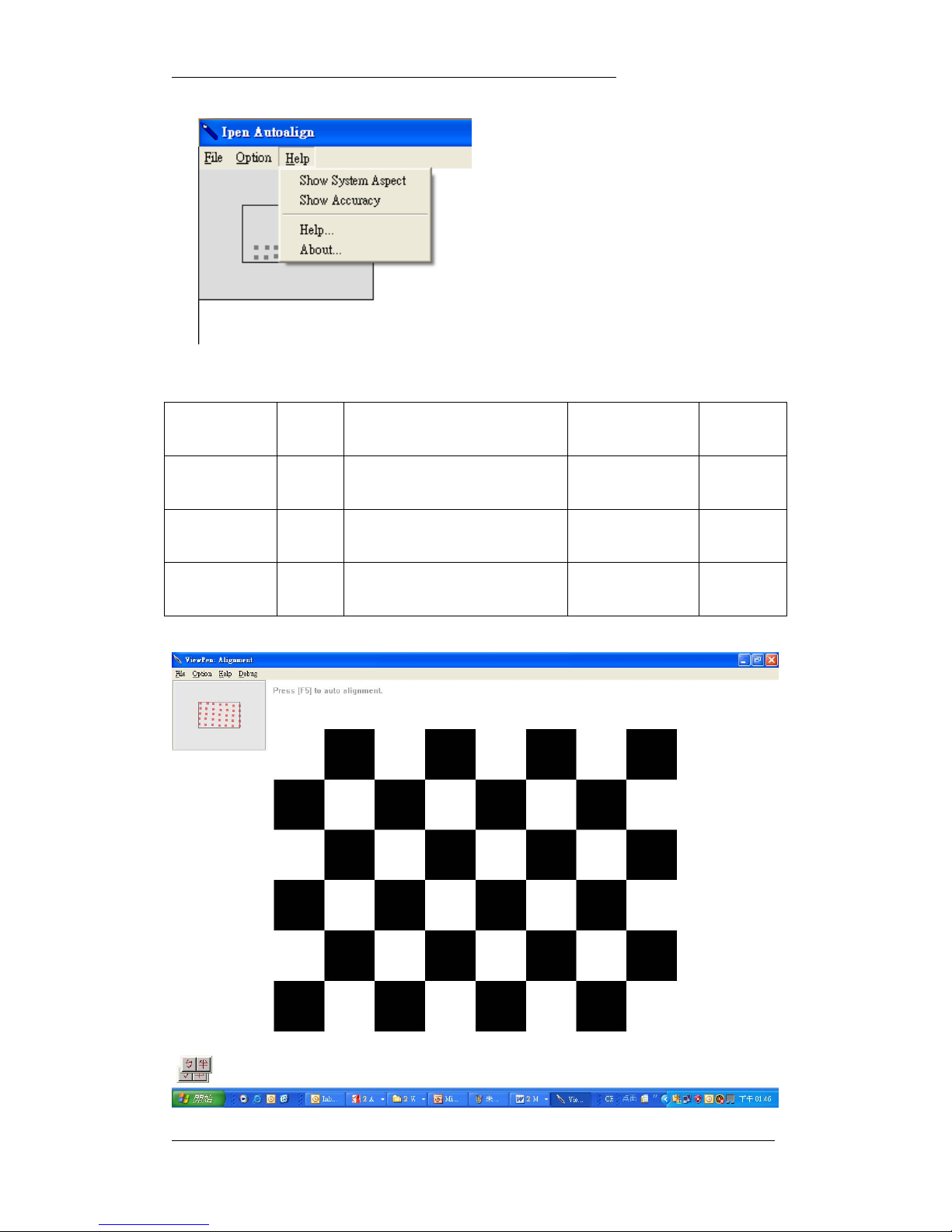
Fig. 7. Option menu and Help menu
3.1.1 In the File menu, as shown in Fig 7, there are two critical items under File menu.
Menu Hot Key Description Purpose Ref
Auto Align F5 Show alignment screen & auto align For user alignment Fig6
Better Preview F11 To get better preview alignment nuts
shown
Ease to align Fig 6
Exit Alt-CTL-X Close application Close application Fig 6
Table 3: Major selection item.
Page 15
iPen User’s Manual Micro- Nits Co. LTD
Version 1.1.1 Date: July/2006 Page: 15 of 24
Figure 8: Auto alignment screen
3.1.2 As shown in Fig 6.1. In the Aspect menu, there are three items showing different
display screen image aspect ratio, the default is 4:3 or 1024 : 768 or 800 : 600.
If your projector has different aspect ration, please select or input the appropriate one.
In ViewPen application, the smart device can auto detect the screen aspect ratio.
3.1.2.1 You can select to auto detection once and use the detected value as the default
setting for next and future alignment.
3.1.2.2 You can also select to use item 3 to make sure the smart device to detect the
screen aspect ratio for every alignment.
3.1.2.3 In Fig 6, it shows 4 gain selections:
Gain Low, Gain Medium, Gain High, Gain Extra High.
The default is Gain high, you can always selection a higher one, however, if you feel the
background noise incuse impact for the performance, please select next lower gain level.
3.1.2.3, In Fig 6, the last item in Option menu, user can check to select the application
icon in the task bar or hide to tray after alignment
3.1.3 In Help menu, there are 4 items.
Help Description
Show Sensor Code Showing Sensor info Refer to Fig 9
Align Accuracy Display alignment accuracy Refer to Fig 10
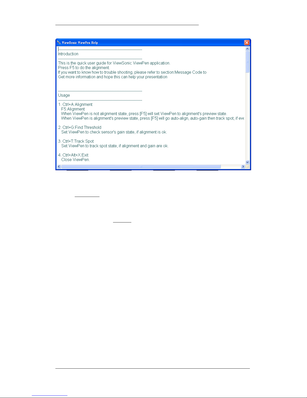
Help Press F1 to get help info Refer to Fig 12
About Display iPen info Refer to Fig 13
Table 4: Help menu selection item
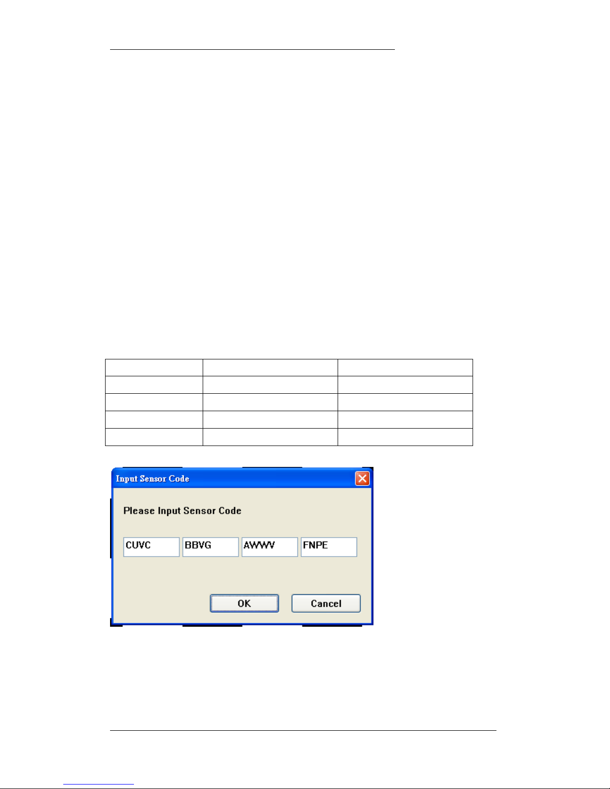
Figure 9: Sensor code
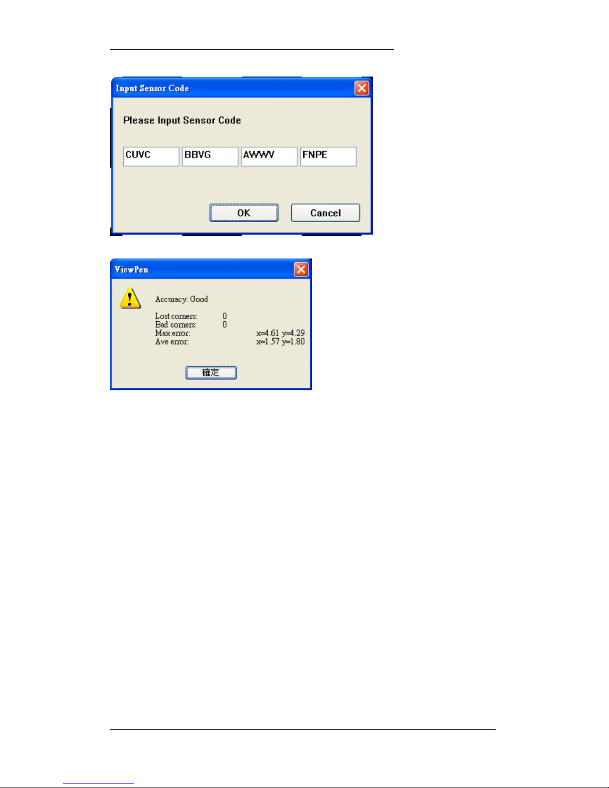
3.1.4 User can select from Option menu, “update sensor code” to correct the accuracy of
alignment performance. If user is will to try another set of data. The code is on the label at the
bottom of sensor base.
Page 16
iPen User’s Manual Micro- Nits Co. LTD
Version 1.1.1 Date: July/2006 Page: 16 of 24
Figure 10: Sensor code input
Figure 11: Alignment accuracy information
3.1.5 To make sure the alignment performance, if the average error is too high, the application
will ask the user to repeat the alignment step.
Page 17
iPen User’s Manual Micro- Nits Co. LTD
Version 1.1.1 Date: July/2006 Page: 17 of 24
Figure 12: Readme.txt
3.2 Auto mode
After pressing F5
to go to the auto alignment mode as shown in Fig 8. User can see a
rectangle on the top left corner on screen and displaying maximum 7 x 5 nuts. Using the
Nuts as the targets to do the coarse alignment to make sure the screen image falls within
the scanned area, then press F5
again to automate the align and tracking procedures,
everything will be done automatically. After this is successfully done, the application
windows will shrink to the task bar and working in the background.
Page 18
iPen User’s Manual Micro- Nits Co. LTD
Version 1.1.1 Date: July/2006 Page: 18 of 24
4. User Tips
4.1 During setup
4.1.1 In the auto-alignment mode, there is a preview window on the top left corner
of the application window that is used for basic aiming. Sometimes during very
tough situation, there is no or less square nuts shown in the preview window.
This is still OK to go for auto alignment, or you can press F11 to get clear
preview ,since the application is smart enough to correct it, if the scanned
area covers the screen image.
4.1.2 The aiming does not need to be very accurate or perfect; however, the
scanned area should cover the full projection image.
4.1.3 During either auto alignment mode or manual mode, please make sure that
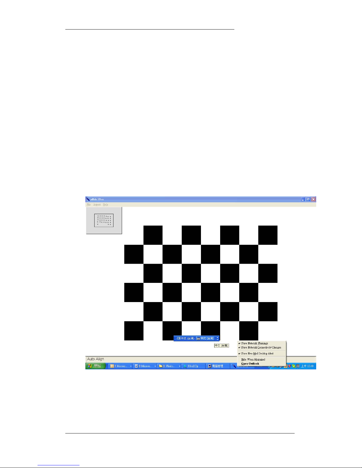
there are no other icons or balloons show up in the application as shown in Fig
20. These icons might impact on the performance of auto alignment.
Figure 13: Icons or balloons might impact on alignment performance
Page 19
iPen User’s Manual Micro- Nits Co. LTD
Version 1.1.1 Date: July/2006 Page: 19 of 24
4.2 During writing and presentation
There are some tips that user needs to pay attention to make the presentation more
enjoyable.
4.2.1 Do not block any of the projected handwriting image by user hands or body.
User can real time watches what he is writing.
4.2.2 Leave more room on each side of the screen for presenter, so the presenter
does not need to stay inside the image.
4.2.3 Some of the control icons or tool bars can move to the lower side of screen
image, this can help presenter to have a smooth operation, especially in the
very large screen situation.
4.2.4 For remote sketch or marking, or icon selection, move the red laser spot to the
destination and release the laser button. The cursor will be staying on the
icons or item that you want, and then press the Left1 button as clicking on the
left button to select the action. To push both laser button and select button at
the same time to activate the action, it may be difficult to many users.
4.2.5 Due to the mechanical design of the screen touch mechanism, please press
the handhold device tip on the image screen down as normal pen.
4.2.6 It is convenient to use PowerPoint 2003 for presentation. In the show mode,
the hand writing function provide excellent capability for presentation.
4.2.7 MS Windows OneNote2003 is also a very good application for i-Pen to work.
Please refer to MS OneNote2003 web site to learn more about the
performance to check what OneNote can offer to you.
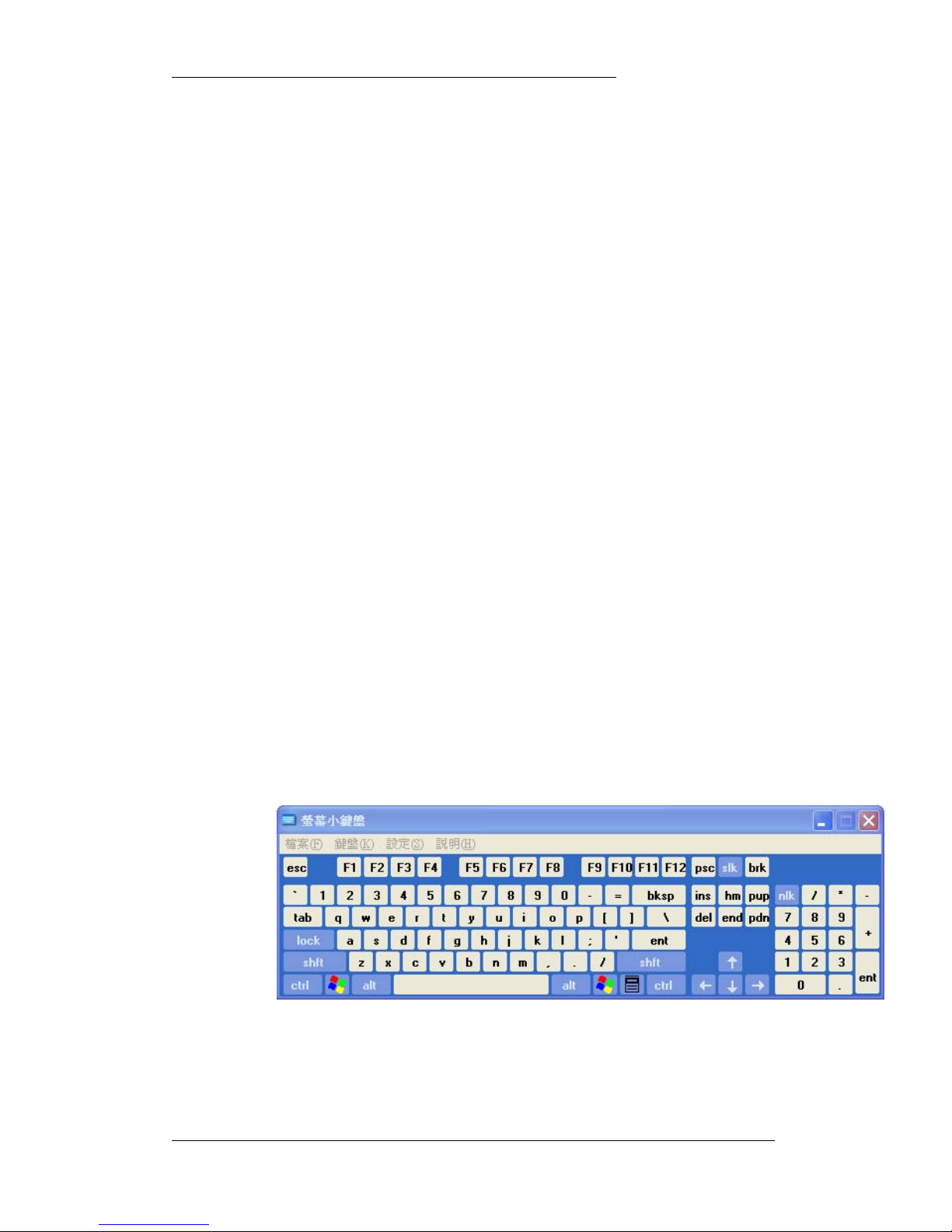
4.2.8 The product is designed not to use key board as much as possible, the other
way to do input without leaving the screen is to use MS Windows screen
keyboard as shown in Fig 14.
Figure 14: Screen key board
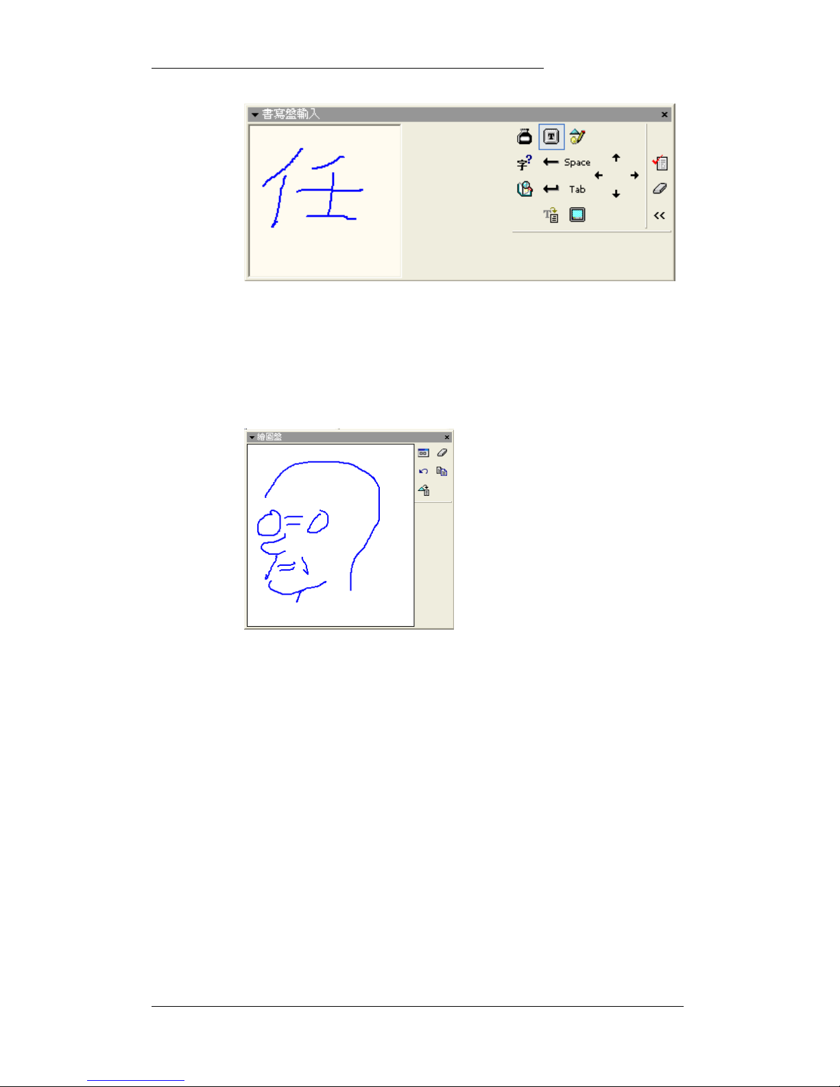
4.2.9 For most of Asian character input, user can take the advantage of MS
Windows XP handwriting recognition as shown in Fig 15.
Page 20
iPen User’s Manual Micro- Nits Co. LTD
Version 1.1.1 Date: July/2006 Page: 20 of 24
Figure 15: Asian Font hand writing input pad
4.2.10 Presenter can also use the English mode for handwriting recognition input
mode to replace the function of screen keyboard. This is also a recommended
input method
4.2.11 To insert important annotation in Word application, you can do with the help of
drawing pad provided by Windows operation system, as shown in Fig 16.
Fig 16. Drawing pad for annotation to any Office 2003 application.
Page 21

iPen User’s Manual Micro- Nits Co. LTD
Version 1.1.1 Date: July/2006 Page: 21 of 24
5. Trouble Shooting
5.1 Is the H/W connection OK?
5.1.1 The sensor status of electrical connection to PC can be confirmed by looking
at the LED light on the sensor base.
5.1.2 Presenter can check the wireless handhold communication to sensor base
by click right, left button or push the cursor move button. If it does not
respond as what you expect, please check the battery status. You can check
the intensity of red laser light spot. Please swap with two good 3A batteries.
5.2 Is the S/W installation OK
5.2.1 Check the file folders are build with the right files copied in the directory.
5.3 Is the alignment OK?
5.3.1 If the alignment is done, however, the accuracy is very worse, please check
the sensor code is the same as printed on the sensor base.
5.3.2 If the alignment is showing bad alignment accuracy, please make sure the
projection screen image has the right aspect ratio as shown in application
option menu. You can also check in the application Help menu, show system
aspect ratio.
5.4 No Capture Device?
5.4.1 Please check the USB plug is connected and the LED on the sensor is on.
5.4.2 Make sure other application is not using this sensor device.
5.5 Is your initialized parameter OK?
5.5.1 If it is always some trouble to do the automated alignment, please press F11
to get optimized parameter.
5.6 What if I do not see the alignment square nuts?
5.6.1 Under some very critical environment, it is true that the square nuts can not
be seen in the preview window. Please press F11 to get better preview.
However, the automation alignment might still be able to match the image
perfectly.
5.6.2 If the automation alignment does not work, please make sure the sensor is
aiming the screen. The screen surface is flat and diffusive and no other stuff
inside the area of the image.
Page 22

iPen User’s Manual Micro- Nits Co. LTD
Version 1.1.1 Date: July/2006 Page: 22 of 24
6. Warranty
Micro-nits Limited Warranty
Thanks for your purchase of a Micro-Nits Product. We at Micro-Nits seek to maintain
the highest quality and workmanship in our products in order to give you, our
customer, value for money and a quality product synonymous with the standard
provided by Micro-Nits.
Micro-Nits warrants to you, the original end-user purchaser and holder of this
warranty, that the retail hardware product herein is free of material defects in
materials and workmanship at the date of purchase. In the event that the hardware
product proves defective during the first 12 months of your purchase ("Warranty
Period"), then upon provision of your proof of purchase, you are entitled to return
the hardware product to us for repair with new or reconditioned parts, or for
replacement with a new or refurbished model that is the same or similar to the
original (at the discretion of Micro-Nits). This warranty is non-tr ansferable and
expressly excludes any product that has not been purchased as new from an
authorized Micro-Nits source. Further, this warranty is ONLY applicable in the
country or territory where the product was purchased. Micro-Nit disclaims the
applicability of all express and implied warranties on the installation software
accompanying this product. You are specifically advised to make a backup copy of
any software provided with the product.
Micro-Nits further warrants the repaired or replaced product to be free from
defects in material and workmanship for a period of ninety (90) days from the date
of repair or replacement, or the remainder of the warranty period, whichever is the
greater. If Micro-Nits undertakes repair or replacement of the product, Micro-Nits
may use new or reconditioned parts, and any returned parts or product from you
that have been replaced become the property of Micro-Nits. Please note that the
return procedures do not apply to Micro-Nits products that are not sold in Micro-Nits
retail packaging or Micro-Nits products that are obtained as a result of the purchase
of a non- Micro-Nits product.
To the extent permitted by applicable law, your Warranty does not apply to normal
wear and tear; damage or loss of data due to interoperability with current and/or
future versions of operating system or other current and/or future software and
Page 23

iPen User’s Manual Micro- Nits Co. LTD
Version 1.1.1 Date: July/2006 Page: 23 of 24
hardware; alterations (by persons other than Micro-Nits or its authorized repair
agents); damage caused by operator error, or non-compliance with instructions as
set out in the user manual or other accompanying documentation; damage caused
by acts of nature such as floods, storms, fires, and earthquakes, etc; products
evidencing the product's serial number has been tampered with or removed; misuse,
neglect, and improper handling; damage caused by undue physical or electrical
stress; counterfeit products; damage to or loss of a product during shipment to or
from Micro-Nits; damage or loss of data caused by a computer virus, worm, Trojan
horse or memory content corruption; failures of the product which result from
accident, abuse, misuse (including but not limited to improper in stallation,
connection to incorrect voltages, and power points, or failures caused by products
not supplied by Micro-Nits); damage caused by moisture, corrosive environments,
high voltage surges, shipping, or abnormal working conditions; damage caused by
any batteries or other power source not provided with the product; or any
accompanying items not bearing the Micro-Nits serial number provided with the
product, or in the case of communications products, the use of the product outside
the borders of the country intended for use (as indicated by local telecommunication
approval stickers).
In no event will Micro-Nits liability or damages to you, or any other person, ever
exceed the purchase price you paid for the product, regardless of the form of the
claim.
In addition, Micro-Nits also disclaims any obligation to support products for all
operating environments, for example, by ensuring interoperability with all current
and/or future versions of software or hardware.
In no event shall Micro-Nits or its licensors be liable for any indirect, incidental,
special or consequential damages, or damages for any personal injury, bodily injury
(including death) to any person, or for any lost profits, savings data or loss of use
arising from or relating to the use of this product, even if Micro-Nits or its licensors
have been advised of the possibility of such damages.
NOTE: This warranty gives you specific legal rights. You may have other rights, which
vary from country to country. Certain limitations in this warranty are not permitted by the
jurisdiction of some countries, so some limitations here may not apply to you.
Page 24

iPen User’s Manual Micro- Nits Co. LTD
Version 1.1.1 Date: July/2006 Page: 24 of 24
Federal Communication Commission Interference Statement
This equipment has been tested and found to comply with the limits for a Class B
digital device, pursuant to Part 15 of the FCC Rules. These limits are designed to
provide reasonable protection against harmful interference in a residential
installation. This equipment generates, uses and can radiate radio frequency
energy and, if not installed and used in accordance with the instructions, may cause
harmful interference to radio communications. However, there is no guarantee that
interference will not occur in a particular installation. If this equipment does cause
harmful interference to radio or television reception, which can be determined by
turning the equipment off and on, the user is encouraged to try to correct the
interference by one of the following measures:
- Reorient or relocate the receiving antenna.
- Increase the separation between the equipment and receiver.
- Connect the equipment into an outlet on a circuit different from that to
which the receiver is connected.
- Consult the dealer or an experienced radio/TV technician for help.
FCC Caution: Any changes or modifications not expressly approved by the party
responsible for compliance could void the user's authority to operate this
equipment.
This device complies with Part 15 of the FCC Rules. Operation is subject to the
following two conditions: (1) This device may not cause harmful interference, and (2)
this device must accept any interference received, including interf erence that may
cause undesired operation.
This transmitter must not be co-located or operating in conjunction with any other
antenna or transmitter
Industry Canada Notice to Users (Industry Canada Statement)
Operation is subject to the following two conditions: (1) Thi s device may not ca use
harmful interference, and (2) this device must accept any interference received,
including interference that may cause undesired operation.
 Loading...