

Page 1

www.micronicsflowmeters.com
USER'S GUIDE
Installation & Operation
Instructions
Area-Velocity Flow Meter
Model UF AV5500
Manual Series A.1
Page 2

Note: This page has been left blank intentionally.
Page 3

Page 3
UF AV5500 Area-Velocity Flow Meter
INDEX
CONNECTIONS ................................................................................................ 4
FUNCTION TEST .............................................................................................. 4
KEYPAD SYSTEM ............................................................................................ 6
CALIBRATION MENU ..................................................................................... 7
ICONS ................................................................................................................. 8
MESSAGE ICON ............................................................................................... 9
STATUS.............................................................................................................. 9
PASSWORD ..................................................................................................... 10
MENU SELECTIONS ...................................................................................... 11
UNITS/MODE .................................................................................................. 11
CALIBRATION................................................................................................ 13
RELAY PARAMETERS .................................................................................. 18
DATA LOGGING............................................................................................. 19
COMMUNICATION (OPTIONAL) .................................................................... 21
SPECIAL FUNCTIONS ................................................................................... 22
INSTALLATION – SENSOR LOCATION ..................................................... 24
ENCLOSURE INSTALLATION ..................................................................... 31
FIELD TROUBLESHOOTING ........................................................................ 32
APPLICATIONS HOTLINE ............................................................................ 35
PRODUCT RETURN PROCEDURE ............................................................... 35
APPENDIX A – OPTIONS ............................................................................... 37
MODBUS® COMMUNICATION ................................................................... 43
SPECIFICATIONS ........................................................................................... 58
IMPORTANT NOTE: This instrument is manufactured and calibrated to meet product specifications.
Please read this manual carefully before installation and operation. Any unauthorized repairs or
modifications may result in a suspension of the warranty.
Available in Adobe Acrobat pdf format
Page 4
Page 4
UF AV5500 Area-Velocity Flow Meter
CONNECTIONS
POWER INPUT: 100 to 240 VAC 50/60Hz. No adjustments are necessary for voltages within this
range. Connect L (Live) N (Neutral) and AC Ground.
Optional DC: 9-32 VDC. Connect to + and - terminals.
Optional Thermostat and Heater modules are available rated for 115 VAC or 230 VAC.
IMPORTANT NOTE: AC power input and relay connection wires must have conduit entry to the
instrument enclosure. Installation requires a switch, overcurrent fuse or circuit breaker in the building (in
close proximity to the equipment) that is marked as the disconnect switch.
Risk of electric shock. Loosen cover screw to access connections. Only qualified personnel
should access connections.
Note: Use of instrumentation over 40°C ambient requires special field wiring.
Note: User replaceable fuse is 2 Amp 250V (T2AL250V).
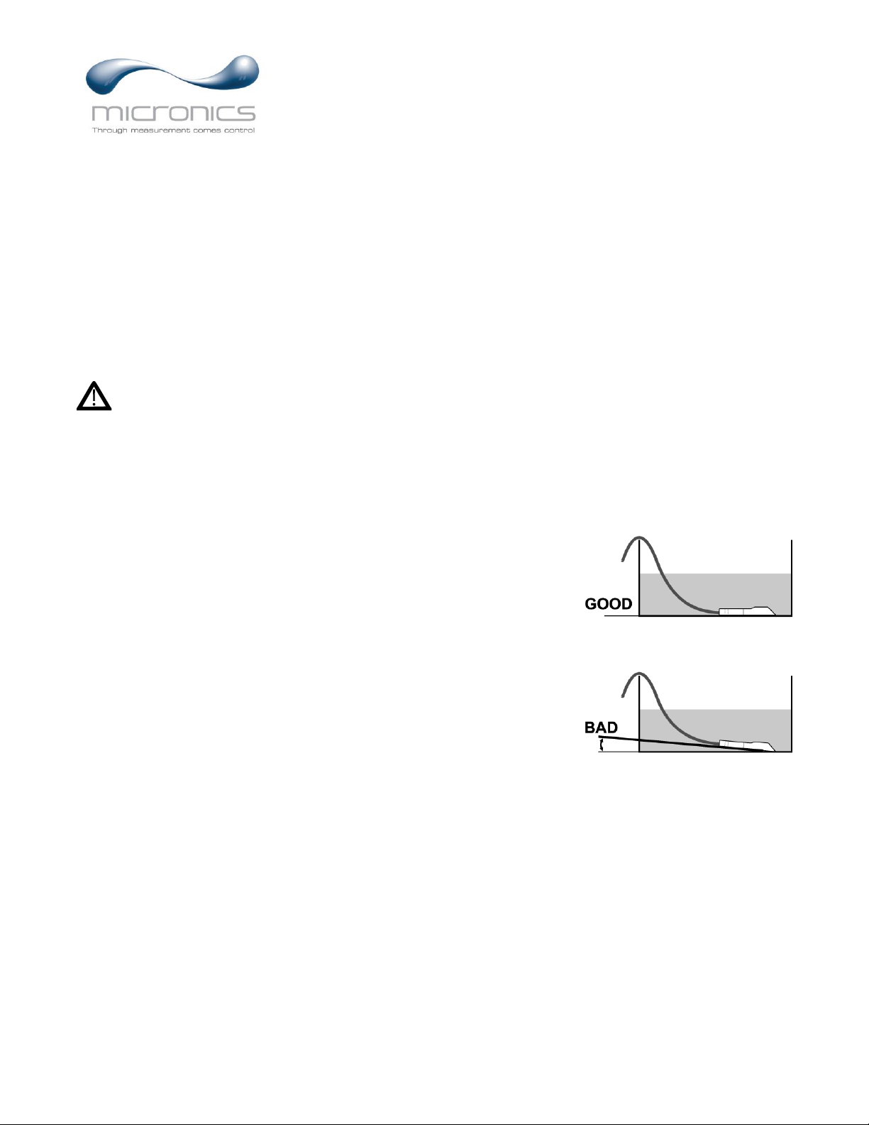
FUNCTION TEST:
Connect the sensor to the sensor terminals as shown on next page, then
apply power. Allow 30 seconds for the UF AV5500 to initialize.
A. Place QZ02L sensor (flat to the bottom) in a bucket of water
about 6” deep and press the programing button to view
the status page which shows level and velocity. Stir the
water to see a velocity reading.
Page 5

Page 5
UF AV5500 Area-Velocity Flow Meter
CONNECTIONS
AC
L N
NO
C
NC
NO
C
NC
–
+
4-20mA
FLOW
RLY2
RLY1
NCCNONCCNONCCNONCC
NO
RLY3 RLY4 RLY5 RLY6
EXTRA RELAYS OPTION
POWER
INPUT
HEATER OPTION
SENSOR
GND
AC
GND
SERIAL COMMUNICATION OPTION
RS-485
Output
+ G
4-20mA
VELOCITY
4-20mA
LEVEL
+ +– –
BLK
SENSOR
RCVR
GND
GND
TMTR
GR N
WHT
CORE
GND
Page 6

Page 6
UF AV5500 Area-Velocity Flow Meter
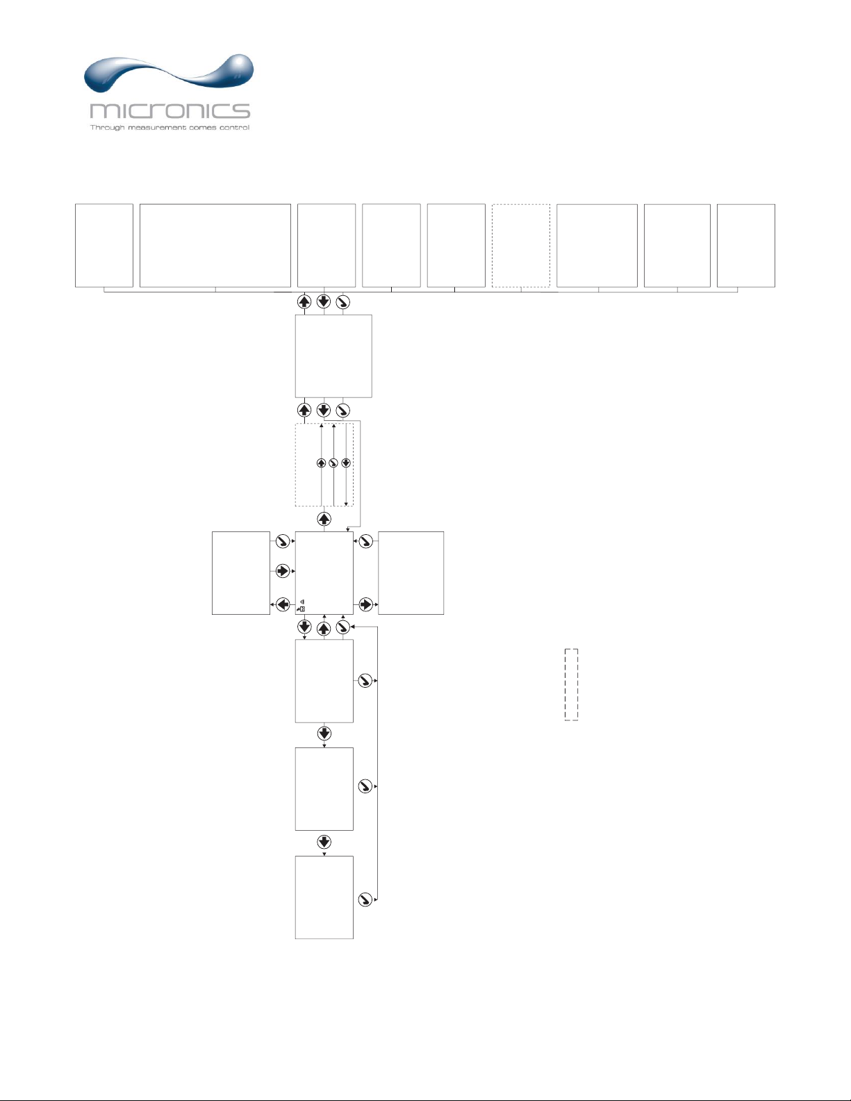
KEYPAD SYSTEM
The UF AV5500 uses a menu system. Arrows show the four directions to leave a menu box. Pressing a
corresponding keypad arrow will move to the next item in the direction shown. Move the cursor
(underline) under numerals and increase or decrease numerals with the and keys.
To store settings permanently (even through power interruptions), press ✓.
Page 7
Page 7
UF AV5500 Area-Velocity Flow Meter
CALIBRATION MENU
- - P ass wo r d- - - - - - - - - -
Pas swo r d
00 0 0
- - Uni t s / Mode- - - - - - - -
Mo d e
Fl o w
Li n ear
i n
Vo l ume
USG
Mul t i pl i er
x 1
Ve l oc i t y
f t / s
Fl o w
USG/ m
Temper at ur e
C
USG/ m
Tot 20 1 3 0. 8 USG
Rel ays 1 2 3 4 5 6
0.000
- - Me ss a ge - - - - - - - - - - -
Da t a L o g
Log g i ng
d
Log Us e 0%Se ns or
Good
Temp e r at ur e
24C
- - S t at u s - - - - - - - - - - - -
Le v e l
0. 00 f t
Ve l oc i t y
0. 0 0 f t / s
Fl o w
0. 00 0 f t / s
Mi n F l ow 0. 0 0 0 USG
Si gna l St r engt h 0%
Si gna l Cu t o f f 5% E
C
100 %
c ho on f i denc e
- - Me nu Sel e c t i ons - - - -
Uni t s / Mo de
Ca l i b r at i on
Ch an n e l Se t u p
Re l a y Par amet er s
Da t a L o g g i n g
Communi c a t i o n
Sp e c i a l Func t i ons
Si mul at i o n
Co nf i gur a t i o n
OPTIONAL FEATURES
- - 2 4 hr l og- - - - - - Fl o w
Dat e
Feb. 1 2 / 2 0
10
501 3 8 USG
Tot al
3 4. 8 2 USG/ m
Av er a g e
52. 2 0 USG/ m
Max i mum
11 : 0 8 : 0 0
Max Ti me
0. 00 0 USG/ m
Mi ni mu m
9: 1 5: 0 0
Mi n T i me
- - 2 4 hr l og- - - - - L e v e l
Dat e
Feb. 1 2 / 2 0
10
0. 00 0 f t
Av er a ge
0. 00 0 f t
Max i mum
11 : 0 8 : 0 0
Max Ti me
0. 00 0 f t
Mi ni mum
9: 15 : 0 0
Mi n T i me
- - 2 4 hr l og- - Vel o ci t y
Dat e
Feb. 12 / 2 0
10
0. 00 0 f t / s
Aver a g e
0. 00 0 f t / s
Ma x i mu m
11: 0 8 : 0 0
Ma x T i me
0. 00 0 f t / s
Mi ni mum
9: 1 5 : 0 0
Mi n Ti me
- - Re l a y Par amet er s- -
Rel a y
1
Funct i on
Fl o w
/ mi n
On
100 0 USG
/ mi n
Of f 0. 0 00 USG
- - Sp ec i al Fu n c t i o n s -
La n gu a g e
Eng l i s h
An a l og Ou t 4- 20 mA
Ba c kl i gh t
Hi g h
Re s e t To t a l i z er NO
Ne g . T ot a l s
NO
Re v . Fl ow
Of f
Ca p t u r e Pa r
No
Ca p t u r e WFNo Re s t o r e De f a u l t s NO
Ne w Pa s s wo r d 00 0 0
- - Dat a Log g i ng - - - - - - -
Lo g Si t e I D
0
Mo d e
Fl o w
Fi l e F o r mat
. LG2
Dat e
Feb
9
27 / 2 01
Ti me
11: 2 7 : 4 0
I nt er v al
10s e c
Dat a L o g
Lo g g i n g
- - Co n f i g ur at i o n - - - - -
Se r i a l # 0 00 0 1 2 3 4 5
Ut i l i t y
4 . 1
1. 2 . 0
So n a r
1. 3 1 . 1
Dop pl e r
1. 1 . 11
24
Lo g ge r
1. T
6
Rel ay s
Ana l og Ou t
3
- -
- - - - -
Cha nn e l Se t u p -
Ty p e
Roun d
0. 7 5f t
Pi p e I D
- - S i mul a t i o n- - - - - - - -
Te s t
Ac t u a l
Le v el
0. 00 i n
Vel oc i t y
10f t / s
Fl o w 1 9 82 . 88 USG/ m
4- 2 0mA Le v el 2 0 . 0 0
4- 2 0mA Vel o c i t y 20. 00
4- 2 0mA Fl ow 20. 00
Rel ay s 1 2 3 4 5 6
- - Co mmuni c a t i o n- - - - -
Pr o t o c ol
Modb u s
Ad d r e s s
001
BPS
96 0 0
Pa r i t y
Even
St o p Bi t s
1
* Menu only appears if "New Password" has been
changed from 0000 in "Special Functions" menu.
*
- - Cal i b r a t i on- - - - - - -
Ran g e
Max
18 0 . 0 0 i n
Mi n
8. 00 i n
L e v el
Max
18 0 . 0 0 i n
Mi n
1. 00 i n
2 0mA
18 0 . 0 0 i n
4 mA
0. 00 i n
V e l o c i t y
2 0mA
1 0. 00 f t / s
4mA
0. 0 0 f t / s
F l ow
Mi n
0 . 0 0 g al / m
20 mA 50 0 . 0 0 g a l / m
4mA
0 . 0 0 g al / m
L v l Of f s e t
0. 0 0 i n
Si gn a l Cut o f f
1 0 %
Da mpi ng
Ve l o ci t y
1 0 %
L eve l
1 0 %
L OE Ti me
3 0 s e c
C al Co n s t a n t 1. 0 0 0
Page 8
Page 8
UF AV5500 Area-Velocity Flow Meter
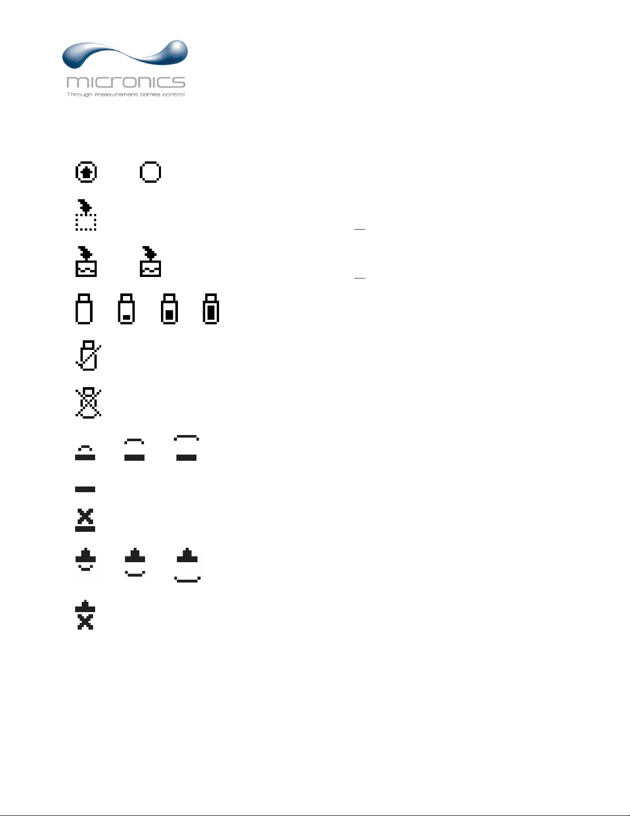
ICONS
Echo OK (PZxx series level sensor option).
Echo . loss
3.2.1.
No Echo (PZxx series level sensor option).
1. 2. Message waiting. Press .
Data logging .off
1.
2. Data logging .on
1. 2. 3. 4.
USB file download.
File download completed.
Download Error.
Echo OK.
Dry sensor. No water in pipe/channel.
3.2.1.
Page 9

Page 9
UF AV5500 Area-Velocity Flow Meter
MAIN DISPLAY
The main display shows the units selected from the Units/Mode menu, Flow or
Velocity rate being measured, TOTALIZER and RELAY states. The UF AV5500
will start-up with this display.
MESSAGE ICON
Press from the main display to view temperature measurement, status of the
data logger and error/warning messages provided by the instrument. The
Message Icon will appear on the main display if error messages are being
generated by the instrument. Press ✓ to return to the main display.
STATUS
Press from the MAIN display to view instrument status.
Level Displays the measured level in units selected in the
Units/Mode menu.
Velocity Displays the measured velocity in units selected in the
Units/Mode menu.
Flow Displays the flow rate in units selected in the
Units/Mode menu. The flow is calculated based on the
individual level and velocity data, and the channel
shape and size programmed in the Channel Setup menu.
Min Flow Displays a read-only value of the minimum flow cutoff.
Any flow rate measured below this Min Flow will be
displayed as 0 on the LCD display.
Signal Strength Displays the strength of the received Doppler velocity
signal on a 0-100% scale.
Signal Cutoff Displays a read-only value for signal cutoff. If the
Signal Strength is less than the Signal Cutoff, velocity
will be reported as 0. This setting may need to be
adjusted in case of unstable velocity measurements with
no water moving, or when high levels of industrial
noise are present. The Signal Cutoff can be adjusted in
the Calibration menu.
USG/ m
Tot 2013 0 . 8 USG
Rel ay s 1 2
0.000
- - Mes s age- - - - - - - - - - Dat a L o g Lo g g i n g
dLo g Us e 0%
Se n s o r Good
Temper at ur e 24 C
- - St at u s - - - - - - - - - - - Lev el 0. 0 0 f t
Ve l o c i t y 0. 0 0 f t / s
Fl o w 0. 0 0 0 f t / s
Mi n Fl o w 0. 0 0 0 USG
Si gn a l St r e ngt h 0 %
Si gn a l Cu t of f 5%
Echo Conf i de nc e 10 0 %
Page 10

Page 10
UF AV5500 Area-Velocity Flow Meter
- - St a t u s - - - - - - - - - - - Lev e l 0. 00 f t
Vel o c i t y 0. 00f t / s
Fl ow 0. 000 f t / s
Mi n Fl o w 0. 00 0 USG
Si gnal St r engt h 0%
Si gnal Cut of f 5%
Ec h o Co n f i de n c e100%
STATUS (cont.)
Echo Confidence Displays the confidence of level measurement received
from the QZ02L submerged sensor, or PZ15 level
sensor, on a 0-100% scale. This value is a reflection of
the percent of echoes received from pulses. Example: If
8 pulses are sent from the level sensor and only 4
echoes are received, Echo Confidence will report 50%.
This does not mean that the level is inaccurate, but
instead means the level reading could be susceptible to
a loss of reading should the conditions causing missed
pulses gets worse. Like an increase in solids or bubbles
in the flow steam.
24 HR LOG
Press from the MAIN display to view a formatted flow report from instruments
with a built-in data logger. Press to pan through Flow, Velocity and Level
summaries. Press to scroll down one day or repeatedly to scroll to a specific
date. Up to 365 days can be stored for Flow, Level, and Velocity. Newest date
will overwrite the oldest. Press ✓ to return to the main display.
Inserting a USB drive into the meter while on this screen will transfer 24 HR Log
data to the USB drive in .csv format.
PASSWORD
The Password (a number from 0000 to 9999) prevents unauthorized access to the
Calibration menu.
From the Main Display press the key to get to Password. Factory default
password is 0000 and if it has not been changed, this screen will be bypassed
completely.
A new password can be stored by going to the Special Functions New Password
menu.
If a user password is required, press to place the cursor under the first digit and
or to set the number, then to the second digit, etc. Press or ✓ to
proceed to the Menu Selections screen.
Page 11

Page 11
UF AV5500 Area-Velocity Flow Meter
MENU SELECTIONS
The Menu selections page is used to navigate to specific menus which are
described in more detail on the following pages.
Press or to navigate to different menus, and to enter the selected menu.
UNITS/MODE
At Mode, press the and then the or to select Flow or Velocity. Flow
mode displays the flow rate in engineering units (e.g. gpm, litres/sec, etc.) Press
the ✓ to store your selection then the to the next menu item.
At Linear press the key and then the or to select your units of
measurement. The Linear units define what units the pipe/channel dimensions and
level reading will be displayed in. Typically inches or mm is selected. Press the ✓
to store your selection then the to the next menu item.
At Volume, press the and then the or to select units for volume. Note:
“bbl” denotes US oil barrels. Press the ✓ to store your selection then the to the
next menu item.
At Multiplier, press the and then the or to select the totalizer multiplier.
Multipliers are used when resolution down to single digit is not required, or when
you don’t want to convert from gallons to thousands of gallons, as an example.
Press ✓ to store your selection then to the next menu item.
At Velocity, press the and then the or to select the engineering units for
flow velocity and sonic velocity of the fluid. Press ✓ to store your selection then
to the next menu item.
At Flow, press the and then the or to select the engineering units for
flow rate. Press ✓ to store your selection then to the next menu item.
- - Menu- - - - - - - - - - - - - -
Uni t s / Mode
Cal i br a t i o n
Rel ay Par amet er s
Dat a L oggi ng
Communi c at i on
Sp e c i al Fun c t i ons
Si mul at i o n
Con f i g u r at i o n
Page 12

Page 12
UF AV5500 Area-Velocity Flow Meter
Available Flow Rate Engineering Units:
Abbreviation
Description
Abbreviation
Description
USG/d
US gallons per day
L/d
litres per day
USG/h
US gallons per hour
L/h
litres per hour
USG/m
US gallons per minute
L/m
litres per minute
USG/s
US gallons per second
L/s
litres per second
ft3/d
cubic feet per day
m3/d
cubic meters per day
ft3/h
cubic feet per hour
m3/h
cubic meters per hour
ft3/m
cubic feet per minute
m3/m
cubic meters per minute
ft3/s
cubic feet per second
m3/s
cubic meters per second
bbl/d
barrels per day (1 bbl = 42 USG)
IG/d
Imperial gallons per day
bbl/h
barrels per hour (1 bbl = 42 USG)
IG/d
Imperial gallons per day
bbl/m
barrels per minute (1 bbl = 42 USG)
IG/d
Imperial gallons per day
bbl/d
barrels per second (1 bbl = 42 USG)
IG/d
Imperial gallons per day
USMG/d
US million gallons per day
IMG/d
Imperial million gallons per day
USMG/h
US million gallons per hour
IMG/h
Imperial million gallons per hour
USMG/m
US million gallons per minute
IMG/m
Imperial million gallons per minute
USMG/s
US million gallons per second
IMG/s
Imperial million gallons per second
Page 13
Page 13
UF AV5500 Area-Velocity Flow Meter
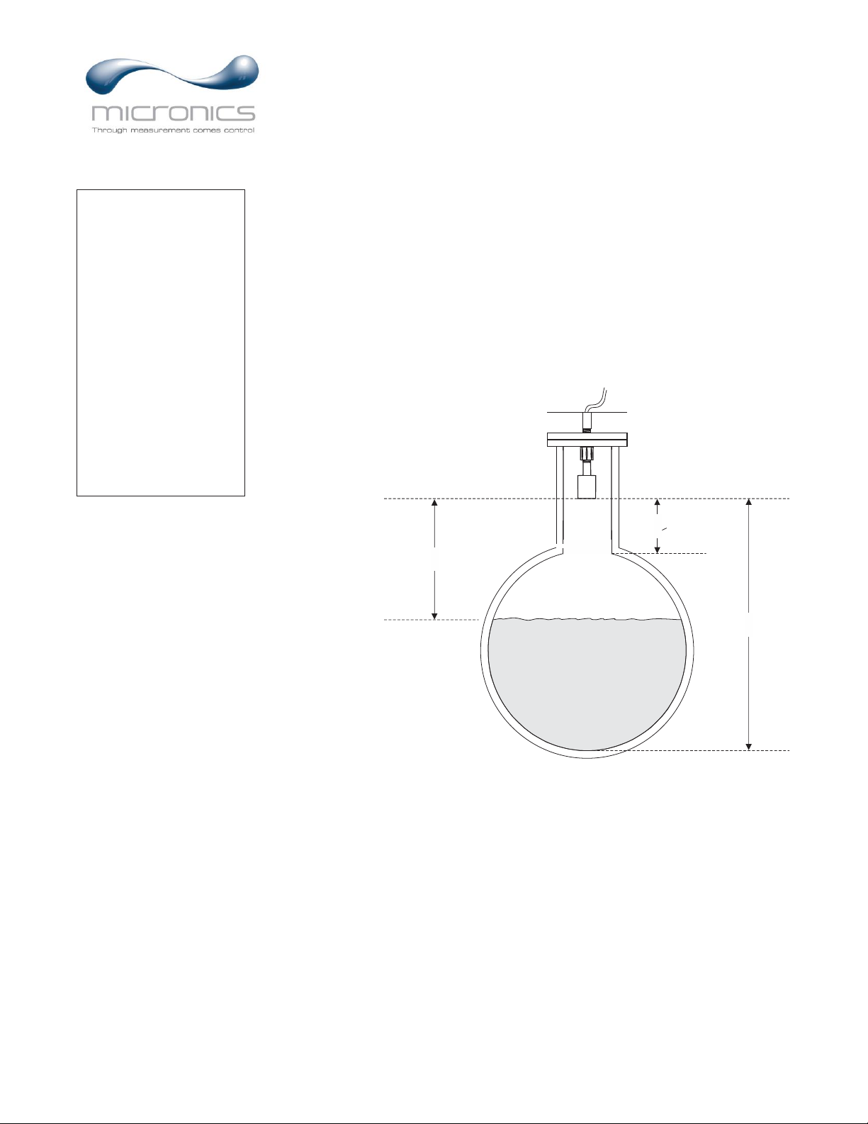
CALIBRATION
Range
Max
Only shown when the level sensor used is a through-air PZ
type. Max range should be set as the distance from the face of
the PZ sensor to the zero level reference point of the
pipe/channel it is installed above. See drawing below.
Min
Only shown when the level sensor used is a through-air PZ
type. Min range should be set as the distance from the face of
the PZ sensor to the maximum water level of the pipe/channel
it is installed above. The water in the pipe/channel should get
no closer than 8 inches for a PZ15-LP sensor type. See
drawing below.
SUNSCREEN
SENSOR
MaxRg
Range
MinRg > dead band
Level
Max
For QZ02L (submersible, default) level sensor, set the
maximum height the level should reach in the system, in units
configured in the Units/Mode menu. If a Round pipe is
selected in the Channel Setup menu, then this value should be
set to the same value as the inside diameter.
Min
For QZ02L (submersible, default) level sensor, set the
minimum height the level should reach in the system, in units
configured in the Units/Mode menu. Minimum level for the
QZ02L sensor is 1 inch, however, this value could be set to a
larger value if you want to ignore levels greater than 1 inch.
20mA
Set the 20mA value for the level analog output, in units
configured in the Units/Mode menu.
- - Ca l i br at i o n - - - - - - -
Range
Max 18 0. 0 0 i n
Mi n 8. 00 i n
Lev el
Max 18 0. 0 0 i n
Mi n 1. 00 i n
20mA 1 80. 00 i n
4mA 0. 0 0 i n
Ve l oc i t y
20mA 10. 00 f t / s
4mA 0 . 00 ft/s
Fl ow
Mi n 0. 0 0 gal / m
20mA 500. 00 g al / m
4mA 0. 00 g al / m
Lvl Of f s et 0. 00 i n
Si gna l Cut of f 1 0 %
Dampi ng
Ve l oc i t y 10 %
Lev el 10 %
LOE Ti me 3 0 s e c
Cal Con s t an t 1. 000
Page 14
Page 14
UF AV5500 Area-Velocity Flow Meter
CALIBRATION (cont.)
4mA
Set the 4mA value for the level analog output, in units
configured in the Units/Mode menu.
Velocity
Min
Only shown when Mode = Velocity in the Units/Mode menu.
When measured velocity is less than the Min Velocity, the
reading on the LCD display and output signals will report 0.
20mA
Set the 20mA value for the velocity analog output, in units
configured in the Units/Mode menu.
4mA
Set the 4mA value for the velocity analog output, in units
configured in the Units/Mode menu.
Flow
Min
Only shown when Mode = Flow in the Units/Mode menu.
When measured flow is less than the Min Flow, the reading on
the LCD display and output signals will report 0.
20mA
Set the 20mA value for the flow analog output, in units
configured in the Units/Mode menu.
4mA
Set the 4mA value for the flow analog output, in units
configured in the Units/Mode menu.
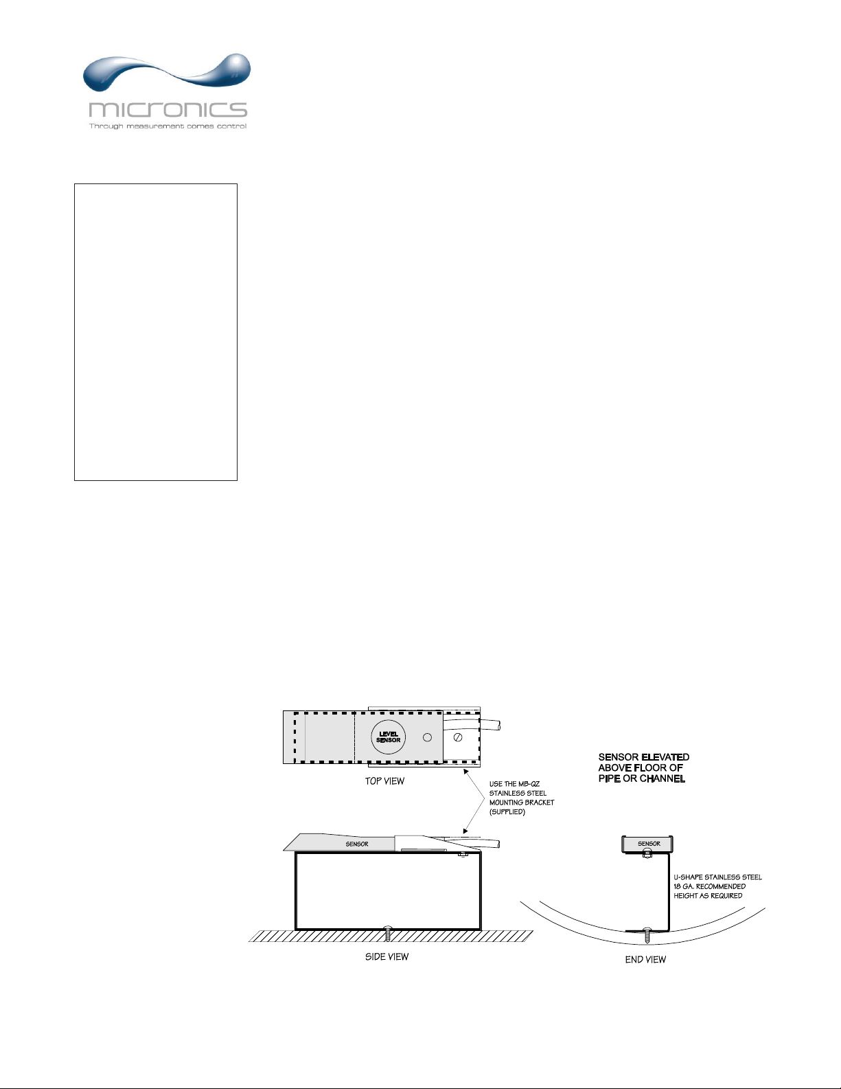
Lvl Offset
For the QZ02L sensor only. Set to 0.00 when sensor is
mounted at the bottom of a channel/pipe. When the sensor is
mounted above the floor, in order to avoid having the sensor
become coated with debris, enter the distance between the
floor and the bottom of the sensor.
- - Ca l i br at i o n - - - - - - -
Range
Max 18 0. 0 0 i n
Mi n 8. 00 i n
Lev el
Max 18 0. 0 0 i n
Mi n 1. 00 i n
20mA 1 80. 00 i n
4mA 0. 0 0 i n
Ve l oc i t y
20mA 10. 00 f t / s
4mA 0 . 00 ft/s
Fl ow
Mi n 0. 0 0 gal / m
20mA 500. 00 g al / m
4mA 0. 00 g al / m
Lvl Of f s et 0. 00 i n
Si gna l Cut of f 1 0 %
Dampi ng
Ve l oc i t y 10 %
Lev el 10 %
LOE Ti me 3 0 s e c
Cal Con s t an t 1. 000
Page 15

Page 15
UF AV5500 Area-Velocity Flow Meter
CALIBRATION (cont.)
Signal Cutoff
Adjust the setting in percent to suppress industrial noise from
potentially being read as Doppler signals. When Signal
Strength is less than Signal Cutoff, the velocity measurement
will report 0.00 on the LCD display.
Damping
Velocity
Set the dampening value for the velocity reading. Lower
values provide fast response to changing velocities, and higher
values provide a slower response. A value of 0 disables
dampening. Factory default value is 10%.
Level
Set the dampening value for the level reading. Lower values
provide fast response to changing levels, and higher values
provide a slower response. A value of 0 disables dampening.
Factory default value is 10%.
LOE Time
Should the level reading be lost because of air or debris in the
system, the LOE Time will cause the meter to hold the last
valid level reading until the LOE Time is expired, at which
point the meter will produce a Loss of Echo alarm message.
Having a LOE Time in the meter means that intermittent air or
debris issues in the system will not cause the meter to lose
flow reading. If you desire that the meter respond quickly to a
Loss of Echo, set the LOE Time to a low value.
Cal Constant
Used to scale the velocity output of the meter. Factory default
is 1.000.
- - Ca l i br at i o n - - - - - - -
Range
Max 18 0. 0 0 i n
Mi n 8. 00 i n
Lev el
Max 18 0. 0 0 i n
Mi n 1. 00 i n
20mA 1 80. 00 i n
4mA 0. 0 0 i n
Ve l oc i t y
20mA 10. 00 f t / s
4mA 0 . 00 ft/s
Fl ow
Mi n 0. 0 0 gal / m
20mA 500. 00 g al / m
4mA 0. 00 g al / m
Lvl Of f s et 0. 00 i n
Si gna l Cut of f 1 0 %
Dampi ng
Ve l oc i t y 10 %
Lev el 10 %
LOE Ti me 3 0 s e c
Cal Con s t an t 1. 000
Page 16
Page 16
UF AV5500 Area-Velocity Flow Meter
CHANNEL SETUP
Round Select Round for open pipes. Set Pipe ID to the inner
diameter of the pipe.
Rectangle Select Rectangle for rectangular channels. Enter the channel
width.
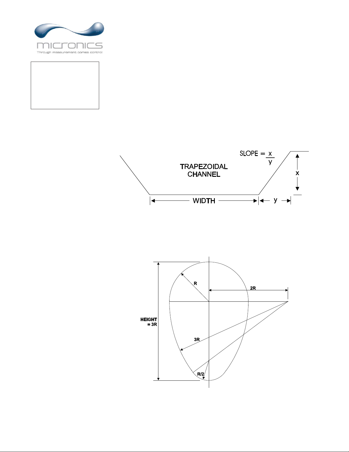
Trapezoid Select Trapezoid for trapezoidal shaped channels. Specify the
Width and Slope of the channel as shown in the following
illustration.
Egg Select Egg for Egg shaped channels. Enter the Height of the
channel.
-- -----Chan n e l Se t upTy pe Rou n d
0. 7 5 f tPi pe I D
Page 17

Page 17
UF AV5500 Area-Velocity Flow Meter
CUSTOM CHANNELS
Reset Data Old data MUST be removed before entering data for a new
channel. Press then press to Yes and press ✓ to clear
old data.
Max Height Enter the maximum height of the channel.
Division Divide the maximum height into equal increments (maximum
of 40) and enter this division value (example 1”, 1 cm etc.)
Increment # Enter the increment number if you want to edit a previous
entry or to skip entering widths for some levels (Note: The
custom channel will interpolate widths between entry points).
Width Enter the measured width of the channel at the level shown
(Note: To enter 0 width you must press and then ✓ to store
a 0 width data point).
Level Displays the level of the channel for each increment and width
entry.
Note:
Custom channel data in equal width increments with variable height
measurements must be converted to the format shown above using the “Channel
Data Translator” PC software.
Page 18

Page 18
UF AV5500 Area-Velocity Flow Meter
RELAY PARAMETERS
Relay Press and or to select a relay (2 relays are standard, 4
additional are optional).
Function Press or to select Off, Pulse, Flow, Velocity or Level.
Pulse Set digits to the flow volume per relay pulse. Use this feature
for remote samplers, chlorinators or totalizers. Minimum time
between pulses is 2.25 seconds and pulse duration is 350
milliseconds.
Flow
On Position the cursor under the numerals and press or to set
digits to the relay On set point.
Off Set digits to the Off set point.
Velocity
On Position the cursor under the numerals and press or to set
digits to the relay On set point.
Off Set digits to the Off set point.
Level
On Position the cursor under the numerals and press or to set
digits to the relay On set point.
Off Set digits to the Off set point.
LOE Mode Specify the state of the relay for loss of echo condition:
Off, On or Hold.
Press ✓ to return to Menu Selections
Page 19

Page 19
UF AV5500 Area-Velocity Flow Meter
DATA LOGGING
Press or to position curser at Data Logging, and to enter. Use or to
position cursor before each menu item and to enter. When settings are
completed press ✓ to store and ✓ again to return to the Main Menu.
Log Site ID Enter a number from 00 to 99. The site ID will become part of
the downloaded file name to help distinguish downloads from
different instruments. Press ✓ to store the setting.
File Format Choose .LG2 to download data in .lg2 format for viewing on
Micronics Logger software. Choose .CSV to download data in
.csv format for import directly to Excel. This menu option can
be changed at any time without adversely affecting existing
data.
Date Press , and or to scroll and select Month, Day and
Year. Press ✓ to store the setting.
Time Press , and or to select the current time in Hours,
Minutes and Seconds. Press ✓ to store the setting.
Interval Press or to select the logging interval. Press ✓ to store
the setting. Micronics recommends choosing an interval which
will give you as much resolution as required and no more.
Choosing too often of an interval for what is required will
result in larger data files, which may take a long time to
download to USB. Reference page 15 for specific download
times. In critical installations, data should be downloaded
often.
Data Log Stop, Start or Delete the log file. Press or to select Delete
and ✓ to delete the log file. Press or to select Start and ✓
to start the logger.
Important Note: You MUST Delete an old log and Start a new log AFTER
having made changes to Log Site ID, Mode, Date, Time and/or Interval for those
changes to be applied.
Important Note: Changing any of the parameters in the Units/Mode menu will
start a new log. It is recommended that you Delete and start a new log after
changing any Units/Mode settings.
View 24-hr formatted Reports on the UF AV5500 display. Press from the main
display to view a formatted flow report from instruments with a built-in data
logger. Press to pan through Level, Velocity and Flow summaries. Press
to scroll down one day or repeatedly to scroll to a specific date. Up to 365 days
can be stored. Newest date will overwrite the oldest. Press ✓ to return to the main
display.
- - Dat a L ogg i n g - - - - - - -
Lo g Si t e I D 0
Mod e Fl ow
Fi l e For mat . LG2
Da t e May 18 / 201 8
Ti me 11: 2 7: 4 0
I nt e r v al 10 s ec
60mi n
3 0 mi n
15mi n
10mi n
5mi n
2mi n
1mi n
3 0 s e c
Da t a L o g St op
St ar t
Del et e
Page 20

Page 20
UF AV5500 Area-Velocity Flow Meter
RETRIEVING LOG FILE
Plug a USB Flash Memory Drive (one is included with the UF AV5500) into the
USB output port on the Panel of the meter. The instrument display will show the
data download icon until the log file is transferred to the memory card. The USB
flash drive may be removed when the icon for download successful appears.
Download file names will appear in this format:
Tag is set according to the Log Site ID entered in the instrument Data Logging
menu.
Download letter will be A for the first download from an instrument. B for the
second, then C etc. At the letter Z a - character will appear indicating that the
maximum number of downloads for that instrument are on the USB flash drive.
Older files can be erased or moved from the flash memory drive or a new memory
drive can be used.
Note: Downloading files in .lg2 format will take approximately 35 seconds per
1% of internal log memory used.
Downloading files in .csv format will take approximately 8 minutes per 1%
of internal log memory used.
OPENING .LG2 FILES
Install Micronics Logger on your PC or laptop. Select File/Open/Instrument Log
(.log) to open the log file from your USB flash drive (not supplied by Micronics).
Data can also be converted to .CSV via Micronics Logger software.
OPENING .CSV FILES
Use a datasheet program such as Microsoft Excel® to import data in a comma
delimited format. Use Excel to manipulate or graph data.
AVFM_ _00A. LG2
Page 21

Page 21
UF AV5500 Area-Velocity Flow Meter
COMMUNICATION (Optional)
Press or to position curser at Communication, and to enter. Use or
to position cursor before each menu item and to enter. When settings are
completed press ✓ to store and ✓ again to return to the Main Menu.
MODBUS Protocol Information:
Transceiver: 2-wire, half-duplex
Data format: 8 Data Bits
Floating Point Byte Order: ABCD
Termination: Jumper JP1 selectable 120Ω resistor. TB1 & TB2 = OFF,
TB2 & TB3 = ON
Biasing: None
Protocol
Choose MODBUS.
Address
Device address for the UF AV5500. Valid range: 001-247
(Default: 001). This number should be unique across the bus.
Press or to scroll, to select digits, and press ✓ to
store the setting.
BPS
Baud rate for the MODBUS communications. Press or
to select, and ✓ to store the setting. Options: 4800, 9600,
19200, 38400, 57600, 76800, and 115200 (Default: 9600).
Parity
Error checking parity for the MODBUS communications.
Press or to select, and ✓ to store the setting. Options:
None, Even, and Odd (Default: Even).
Stop Bits
Press or to select, and ✓ to store the setting. Options: 1
or 2 (Default: 1).
Page 22

Page 22
UF AV5500 Area-Velocity Flow Meter
SPECIAL FUNCTIONS
Language Select English, Spanish or French
Analog Out Select 4-20mA or 0-5V mode for the analog output.
Backlight Select High, Medium or Low for continuous
backlight.
Select Key Hi/Lo for high backlight (for 1 minute) after
a keypress and then Lo backlight until a key is pressed
again.
Select Key High, Med or Low for backlight after a
keypress and then backlight off until a key is pressed
again.
Reset Totalizer Select Yes to erase and restart the totalizer at zero.
This only effects the main totalizer. The 365 day data
remains unchanged.
Neg. Totals Select Yes to have reverse flow readings deducted
from the totalizer. Select No to totalize forward flow
only and ignore reverse flow.
Rev Flow Select On to enable flow direction measurement.
Select Off to disable flow direction measurement so
that flow in either direction is displayed and output as
positive values.
Select Invert to invert the sense of the flow
measurement.
Capture WF This function should only be used when instructed by a
Micronics representative to do so. The function
captures the ultrasonic signal so that it can be evaluated
by Micronics.
Capture Par This function captures the programming parameters in
the meter. Select Yes, wait for Done to appear, then
insert a USB drive into the USB port to transfer the
parameters.
Restore Defaults Select Yes to erase all user settings and return the
instrument to factory default settings.
New Password Select any number from 0000 to 9999 and press ✓.
Default setting of 0000 will allow direct access to the
calibration menus. Setting of any password greater than
0000 will require the password to be entered to access
- - Spec i a l Fun c t i ons -
Language Engl i s h
An a l o g Out 4 - 2 0 mA
Ba c k l i gh t Hi gh
Res et Tot al i z e r NO
Neg . To t a l s NO
Rev . Fl o w Of f
Cap t u r e Par No
Cap t u r e WF No
Res t or e Def au l t s NO
New Pa s s wo r d 0 000
Page 23

Page 23
UF AV5500 Area-Velocity Flow Meter
the calibration menus.
Press ✓ to return to Menu Selections.
SIMULATION
Exercises the 4-20mA (0-5V) outputs, digital display and control relays.
Test Select Maximum and press ✓ to simulate maximum Flow, Level and
Velocity and to output 20mA (5V) to the analog channels.
Select Minimum and press ✓ to simulate minimum Flow, Level and
Velocity and to output 4mA (0V) to the analog channels.
To simulate an intermediate Flow, Level and Velocity set Test to Actual
and then enter a value for the Level and Velocity. The Flow
calculation, analog outputs and control relays will respond to the
simulated values.
Page 24

Page 24
UF AV5500 Area-Velocity Flow Meter
INSTALLATION – SENSOR LOCATION
For the most accurate flow measurement possible, careful consideration should be made to the
placement of the sensor in relation to flow disturbances. In general, the best accuracy will occur where
flow is evenly distributed across the channel/pipe and free of turbulence.
Specific installation considerations are listed and discussed in more detail below.
1. Open Discharges or Pipe/Channel Outfalls
When the QZ02 sensor is to be mounted in front (upstream) of an open discharge or pipe/channel
outfall, the sensor should be placed at least 5 times the maximum head level in front of the
outfall:
Page 25

Page 25
UF AV5500 Area-Velocity Flow Meter
2. Hydraulic Dams
When the QZ02 sensor is to be mounted in front (upstream) of a hydraulic dam, or a Micronics
VD pipe dam, the sensor should be placed at least 20 inches in front of the dam:
3. Pipe Grade
The pipe/channel in which the QZ02 sensor is mounted should not have a grade exceeding 3%:
Pipe / Channel
Side View
Grade 3%
QZ02
Sensor
Page 26

Page 26
UF AV5500 Area-Velocity Flow Meter
1. Flow Profile Distortion
The pipe/channel in which the QZ02 sensor is mounted should be free of bends, tees, sudden
changes in slope, and there should not be objects in the pipe/channel which disturb the flow
profile in front of the sensor.
In general, the QZ02 sensor should be mounted with at least 10 pipe diameters or channel widths
of straight-run upstream, and 5 pipe diameters or channel widths downstream:
Page 27

Page 27
UF AV5500 Area-Velocity Flow Meter
QZ02L VELOCITY-LEVEL SENSOR MOUNTING
Mount the QZ02L sensor with the
stainless steel bracket and hardware
supplied. Ensure that the sensor is
parallel to the water surface (check with
a level). Mount with the tapered end of
the sensor pointing upstream and the
sensor cable pointing downstream.
Clip or tie wrap the sensor cable securely
to the pipe or channel wall.
Note: The mounting bracket is designed
to release the sensor if weeds or rags are
caught by the sensor.
Page 28

Page 28
UF AV5500 Area-Velocity Flow Meter
Page 29

Page 29
UF AV5500 Area-Velocity Flow Meter
OPTIONAL PIPE BAND MOUNTING WITH QZ02L SENSOR
Install the stainless steel pipe band with the sensor mounting
bracket at the invert (bottom) of the pipe. Ensure that the
sensor bracket is parallel to the water surface (check with a
level). Mount so the tapered end of the sensor will point
upstream and the sensor cable will point downstream. (Turn
the ¼” adjustment nut clockwise to expand the bracket and secure to the pipe wall by friction fit.)
Insert the sensor into the mounting bracket and tie-wrap the sensor cable securely to the pipe band using
the holes provided.
OPTIONAL QZ02L-B VELOCITY SENSOR MOUNTING
Mount the velocity sensor at or near the bottom of the channel or pipe in a position where it will be
continuously submerged. The QZ02L-B velocity sensor does not have to be parallel to the water surface.
Position where silt or solids will not build-up on the sensor.
Page 30

Page 30
UF AV5500 Area-Velocity Flow Meter
OPTIONAL PZ15-LP LEVEL SENSOR MOUNTING
Mount the PZ15-LP non-contacting ultrasonic level sensor in an unobstructed position at least 8” (203.2
mm) above the high water level. Install the stainless steel mounting bracket in a horizontal position
(check with a level) and then insert the PZ15-LP sensor.
WATER
PZ1 -LP5
PZ1 -LP MANHOLE MOUNTING5
PZ1 -LP5
WATER
PZ1 -LP PIPE MOUNTING5
QZ02L- VELOCITY SENSORB
8",
203.2mm
8",
203.2mm
Page 31

Page 31
UF AV5500 Area-Velocity Flow Meter
7.4 / 188 mm"
6.46 / 164 mm"
10.94" / 278 mm
10 / 254 mm
"
CONDUIT ENTRY
LOCATION
SIDE VIEW
5.12 / 130 mm"
AV 6FM .1
Area-Velocity
Flow M eter
ENCLOSURE INSTALLATION
Locate the enclosure within 20 ft (6 m) of the sensor (up to 500 ft -150 m optional). The enclosure can
be wall mounted with the four mounting screws (included) or panel mounted with Option PM Panel
Mount kit from Micronics.
Avoid mounting the enclosure in direct sunlight to protect the electronics from damage due to
overheating and condensate. In high humidity atmospheres, or where temperatures fall below freezing,
Option TH Enclosure Heater and Thermostat is recommended. Seal conduit entries to prevent moisture
from entering enclosure.
NEMA4X (IP66) WITH CLEAR COVER
1. Open hinged enclosure cover.
2. Insert #12 screws (supplied) through the four enclosure mounting
holes to secure the enclosure to the wall or mounting stand.
Additional conduit holes can be cut in the bottom of the enclosure
with a hole saw or Greenlee-type hole cutter.
DO NOT make conduit/wiring entries into the top of the enclosure.
Note: This non-metallic enclosure does not automatically provide
grounding between conduit connections. Grounding must be
provided as part of the installation. Ground in accordance with the
requirements of the National Electrical Code. System grounding
is provided by connecting grounding wires from all conduit
entries to the steel mounting plate or another point which
provides continuity.
CLEANING
Cleaning of the electronics is not required as a part of normal
maintenance.
The submersible QZ02L sensor may need to be cleaned in
applications with dirty water, or those with a lot of debris.
Use 1 part household bleach to 20 parts water to clean the
sensor. Immerse for 5 hours and then rinse and dry.
Page 32

Page 32
UF AV5500 Area-Velocity Flow Meter
FIELD TROUBLESHOOTING
The UF AV5500 uses an ultrasonic level sensor to determine flow area and an ultrasonic Doppler sensor
to measure flow velocity.
The QZ02L sensor combines both sensors in one housing.
An optional configuration uses the PZ15-LP “down-looking” level sensor and a QZ02L-B velocity
sensor.
To troubleshoot the UF AV5500, verify correct operation of level and velocity measurements separately.
Note: Selecting “Restore Defaults” in the SPECIAL FUNCTION menu will return the instrument to “as-
shipped” factory settings.
LEVEL (QZ02L SENSOR)
SYMPTOMS
FAULTS
SOLUTIONS
EC percent at zero
- very turbulent flow
- very aerated flow
- relocate sensor or use PZ15-LP
- sensor not level
- level sensor with “Bullseye” level
- sediment/dirt/grease build-up on
sensor
- clean sensor with liquid soap
Level Inaccurate
- sensor not mounted at bottom of
pipe/channel
- set a “Lvl Offset” in Calibration
menu
VELOCITY (QZ02L SENSOR)
SYMPTOMS
FAULTS
SOLUTIONS
- No velocity reading
- grease/sediment on sensor
- improper hook-up
- not enough suspended solids or
aeration in water.
- clean sensor with detergent
- check sensor connections
- drop Alka-Seltzer tab into flow
stream to create bubbles to verify
lack of air in pipe.
- water too clean for Doppler
- perform bucket test to prove
Doppler works.
- Velocity reading too High/Low
- poor velocity profile in
channel/pipe
- Cal Constant changed
- release sensor per suggestions in
sensor location section
- change Cal Constant in
Calibration menu
Page 33

Page 33
UF AV5500 Area-Velocity Flow Meter
SENSOR CABLE RESISTANCE TEST
Unplug the 4-pin green sensor terminal from the Doppler board and connect the sensor wires as shown.
With a multimeter, perform resistance checks for each set of wires. One single loose terminal may cause
false readings.
Test across shield and core of each wire: TMTR (black/white) and RCVR (black). Resistance should be
approximately 82.5K ohms for any cable length. High readings indicate an open circuit and low readings
indicate a short or partial short in the sensor cable.
Unplug the 2-pin green sensor terminal from the level board and connect the multimeter to the pins.
Resistance should be approximately 10K Ohms for any cable length. High readings indicate an open
circuit and low readings indicate a short or partial short.
Resistance measured across these 2 wires also indicates fluid temperature for QZ02L sensor, or ambient
temperature for PZ15-LP sensor.
Page 34

Page 34
UF AV5500 Area-Velocity Flow Meter
Resistance vs. Temperature
Page 35

Page 35
UF AV5500 Area-Velocity Flow Meter
APPLICATIONS HOTLINE
For applications assistance, advice or information on any Micronics Limited contact your Sales Representative,
write to Micronics or phone the Applications Hotline below:
Tel: +44 (0) 1628 810456
Email: sales@micronicsltd.co.uk
Web Site: www.micronicsflowmeters.com
Micronics Limited
Knaves Beech Business Centre
Davies Way, Loudwater
High Wycombe, Buckinghamshire
United Kingdom, HP10 9QR
PRODUCT RETURN PROCEDURE
Instruments may be returned to Micronics for service or warranty repair.
1 Obtain an RMA Number from Micronics -
Before shipping a product to the factory please contact Micronics by telephone or email to obtain an
RMA number (Returned Merchandise Authorization). This ensures fast service and correct billing or
credit.
When you contact Micronics please have the following information available:
1. Model number
2. Serial number
3. Date of Purchase
4. Reason for return (description of fault or modification required)
5. Your name, company name, address and phone number
2 Clean the Sensor/Product -
Important: unclean products will not be serviced and will be returned to the sender at their expense.
1. Rinse sensor and cable to remove debris.
2. If the sensor has been exposed to sewage, immerse both sensor and cable in a solution of 1 part
household bleach (Javex, Clorox etc.) to 20 parts water for 5 minutes. Important: do not immerse
open end of sensor cable.
3. Dry with paper towels and pack sensor and cable in a sealed plastic bag.
4. Wipe the outside of the enclosure to remove dirt or deposits.
5. Return to Micronics for service.
Page 36

Page 36
UF AV5500 Area-Velocity Flow Meter
LIMITED WARRANTY
_____________________________________
Micronics Limited warrants, to the original purchaser, its products
to be free from defects in material and workmanship for a period of
one year from date of invoice. Micronics will replace or repair, free
of charge, any Micronics product if it has been proven to be
defective within the warranty period. This warranty does not cover
any expenses incurred in the removal and re-installation of the
product.
If a product manufactured by Micronics should prove defective
within the first year, return it freight prepaid to Micronics Limited
along with a copy of your invoice.
This warranty does not cover damages due to improper installation
or handling, acts of nature, or unauthorized service. Modifications
to or tampering with any part shall void this warranty. This
warranty does not cover any equipment used in connection with the
product or consequential damages due to a defect in the product.
All implied warranties are limited to the duration of this warranty.
This is the complete warranty by Micronics and no other warranty
is valid against Micronics. Some states do not allow limitations on
how long an implied warranty lasts or limitation of incidental or
consequential damages, so the above limitations or exclusions may
not apply to you.
This warranty gives you specific legal rights, and you may also
have other rights which vary from state to state.
Micronics Limited.
Page 37

Page 37
UF AV5500 Area-Velocity Flow Meter
APPENDIX A – OPTIONS
EXTRA SENSOR CABLE
(OPTION VXC)
Each Micronics UF AV5500 flow meter includes 25 ft. (7.6 m), 50 ft. (15 m) or 100 ft. (30 m) tricoaxial sensor cable. This cable is shielded from electrical interference and is watertight with a
polyurethane jacket. Additional cable and Cable Junction Box (Option JB2X or JB4X) may be ordered
with the flow meter, or the cable may be spliced and extended up to 500 ft (152 m) total length as
required during installation. No adjustment is required when the sensor cable is extended or shortened.
Use only Micronics tri-coaxial VXC shielded cable, or run three RG174U coaxial cables in a metal
conduit.
Extended sensor cable should be installed in rigid metal conduit for mechanical and electrical noise
protection. Recommended installation with a junction box is illustrated below:
62 RG AU COAXIAL
- . MAX TOTAL CABLE LENGTH
500 ft (152m) 62 coaxialRG AU
- CONDUIT RECOMMENDED FOR
MECHANICAL PROTECTION
EXTENDED SENSOR CABLE TO
ELECTRONICS ENCLOSURE
TO ULTRASONIC
LEVEL SENSOR
TO VELOCITY SENSOR
SHIELDED COAXIAL PAIR
- . MAX TOTAL CABLE LENGTH
500 ft (152m) SHIELDED
COAXIAL PAIR
- METALCONDUIT RECOMMENDED
FOR MECHANICAL AND
ELECTRICAL-NOISE PROTECTION
EXTENDED SENSOR CABLE
TO ELECTRONICS ENCLOSURE
Downward AVFM
GND GND
GND GND
CORE
SHIELD
CORE
SHIELD
BLK WHT/
BL K G RN/
BLK WHT/
BLK GRN/
- . MAX TOTALCABLE LENGTH
500 ft (152m) SHIELDED
TRI-COAXIALPAIR
- METALCONDUIT RECOMMENDED
FOR MECHANICAL AND
ELECTRICAL-NOISE PROTECTION
TOGREYLINE SENSOR
EXTENDED SENSOR CABLE
TO ELECTRONICS ENCLOSURE
GND
BL K
BLK GR N/
BLK WHT/
BLK BLK WH T/BLK GR N/
AVFM
Page 38

Page 38
UF AV5500 Area-Velocity Flow Meter
COAXIAL CABLE PREPARATION
VXC UF AV5500 sensor cable can be cut and spliced up to a maximum length of 500 ft (152 m). Cable
ends must be prepared as illustrated below.
Page 39

Page 39
UF AV5500 Area-Velocity Flow Meter
JUNCTION BOX - OPTION JB2X & JB4X
NEMA4X (IP66) polycarbonate Junction Box with terminal strips is available from Micronics Limited.
Includes compression fittings for watertight coaxial cable entries.
Page 40

Page 40
UF AV5500 Area-Velocity Flow Meter
SS PIPE MOUNTING BAND – OPTION VSJ
Page 41

Page 41
UF AV5500 Area-Velocity Flow Meter
SENSOR INTRINSIC SAFETY
When connected through Intrinsic Safety Barriers, the Micronics Sensor Model QZ02L and PZ series
are CSA certified for installation in a hazardous location rated:
Class I, Division 1, Groups C,D
Class II, Division 1, Groups E,F,G
Class III
Intrinsic Safety Barriers may be ordered with the Micronics instrument and are supplied mounted in the
Micronics instrument enclosure. Replacement barrier fuses (Part No. ISB- 011239) may be purchased
separately. The instrument enclosure containing the Intrinsic Safety Barriers must be installed in a nonhazardous location.
Page 42

Page 42
UF AV5500 Area-Velocity Flow Meter
AVFM 6.1
STAHL 9001/02-093-390-101
1 2
3 4
STAHL 9001/02-093-390-101
1 2
3 4
Installed in
Non-Hazardous Location
The intrinsic safety barrier
assemblies installed in the
AVFM limit the voltage 6.1
and current supplied to the
transducers to the values
listed under ‘Barrier
Specifications’. To safely
install Greyline transducer(s)
certified for use in hazardous
locations you must refer to
the installation
drawings/specifications of
the certified transducer(s).
TRANSDUCER
CONNECTIONS
STAHL 9001/02-093-390-101
1 2
3 4
BARRIER SPECIFICATIONS
9001/02-093-390-101
STAHL BARRIER
9.6V, 27 ohms
Um
250V
V0C
9.3V
ISC
390mA
P 0
906.8mWCa4.1µF
La
0.16mH
System Parameters Entity Parameters
GN SPEC ISB3 - -10
(rated 9.6V, 27 ohms)
(rated 9.6V, 27 ohms)
(rated 9.6V, 27 ohms)
TRANSDUCER
GND
Page 43

Page 43
UF AV5500 Area-Velocity Flow Meter
MODBUS® COMMUNICATION
MODBUS® serial interface connections are made at the RS485 card’s terminal block if your UF
AV5500 was ordered with this card, or if one was added after installation. Card location:
SERIAL COMMUNICATION
AC
L N
NO
C
NC
NO
C
NC
–
+
4-20mA
RLY2
RLY1
AC
GND
NCCNONCCNONCCNONCC
NO
RLY3 RLY4 RLY5 RLY6
EXTRA RELAYS OPTION
POWER
INPUT
HEATER OPTION
RS-485
Output
+ G
SENSOR
GND
SENSOR
RCVR
GND
GND
TMTR
Page 44

Page 44
UF AV5500 Area-Velocity Flow Meter
Transceiver:
2-wire, half-duplex
MODBUS Address (MAC address) range:
1-255 (Default: 001)
BAUD rates:
4800, 9600, 19200, 38400, 57600, 76800 or
115200 (Default: 9600)
Data Bits:
8
Parity:
None, Even, Odd (Default: Even)
Stop Bits:
1, 2 (Default: 1)
Termination:
120 Ohms or none (Default: None)
Jumper JP1 position 1 & 2 = OFF (No term)
Jumper JP1 position 2 & 3 = ON (Term)
Biasing:
None
Flow Control:
None
Termination Jumper Position
Function Codes Supported:
01 – Read Coil(s)
02 – Read Discreet Input(s)
04 – Read Input Register(s)
05 – Write Single Coil
06 – Write Single Register
15 – Write Multiple Coils
16 – Write Multiple Registers
17 – Report Slave ID
Page 45

Page 45
UF AV5500 Area-Velocity Flow Meter
MODBUS® MEMORY MAP
Register
Address
Description
Register
Type
Data
Range
Over
Range
Read/
Write
Comments
1
Reset Volume
Total
Coil
NA
NA
Read/
Write
Turn coil ON (1) to reset total on UF AV5500.
Turn coil to OFF (0) once reset is complete.
Register
Address
Description
Register
Type
Data
Range
Over
Range
Read/
Write
Comments
10001
Pulse Output 1
Status
Discreet
Input
NA
NA
Read
(0) indicates pulse output is OFF or inactive.
(1) indicates pulse output is ON or active.
10002
Pulse Output 2
Status
Discreet
Input
NA
NA
Read
(0) indicates pulse output is OFF or inactive.
(1) indicates pulse output is ON or active.
Register
Address
Description
Register
Type
Format Type
Comments
30001
Flow Velocity - ft/s
Input Register
Floating Point Register (1 of 2)
30002
Flow Velocity - ft/s
Input Register
Floating Point Register (2 of 2)
30003
Flow Velocity - m/s
Input Register
Floating Point Register (1 of 2)
30004
Flow Velocity - m/s
Input Register
Floating Point Register (2 of 2)
30101
Flow Rate - GPM
(USG/min)
Input Register
Floating Point Register (1 of 2)
30102
Flow Rate - GPM
(USG/min)
Input Register
Floating Point Register (2 of 2)
30103
Flow Rate - L/sec
Input Register
Floating Point Register (1 of 2)
30104
Flow Rate - L/ssec
Input Register
Floating Point Register (2 of 2)
30105
Flow Rate - ft3/min
Input Register
Floating Point Register (1 of 2)
30106
Flow Rate - ft3/min
Input Register
Floating Point Register (2 of 2)
30107
Flow Rate - m3/hr
Input Register
Floating Point Register (1 of 2)
30108
Flow Rate - m3/hr
Input Register
Floating Point Register (2 of 2)
30109
Flow Rate - USG/sec
Input Register
Floating Point Register (1 of 2)
30110
Flow Rate - USG/sec
Input Register
Floating Point Register (2 of 2)
30111
Flow Rate - USG/hr
Input Register
Floating Point Register (1 of 2)
30112
Flow Rate - USG/hr
Input Register
Floating Point Register (2 of 2)
Page 46

Page 46
UF AV5500 Area-Velocity Flow Meter
Register
Address
Description
Register
Type
Format Type
Comments
30113
Flow Rate - USG/day
Input Register
Floating Point Register (1 of 2)
30114
Flow Rate - USG/day
Input Register
Floating Point Register (2 of 2)
30115
Flow Rate - ft3/s
Input Register
Floating Point Register (1 of 2)
30116
Flow Rate - ft3/s
Input Register
Floating Point Register (2 of 2)
30117
Flow Rate - ft3/hr
Input Register
Floating Point Register (1 of 2)
30118
Flow Rate - ft3/hr
Input Register
Floating Point Register (2 of 2)
30119
Flow Rate - ft3/day
Input Register
Floating Point Register (1 of 2)
30120
Flow Rate - ft3/day
Input Register
Floating Point Register (2 of 2)
30121
Flow Rate - USMG/sec
Input Register
Floating Point Register (1 of 2)
USMG = US Million Gallons
30122
Flow Rate - USMG/sec
Input Register
Floating Point Register (2 of 2)
USMG = US Million Gallons
30123
Flow Rate - USMG/min
Input Register
Floating Point Register (1 of 2)
USMG = US Million Gallons
30124
Flow Rate - USMG/min
Input Register
Floating Point Register (2 of 2)
USMG = US Million Gallons
30125
Flow Rate - USMG/hr
Input Register
Floating Point Register (1 of 2)
USMG = US Million Gallons
30126
Flow Rate - USMG/hr
Input Register
Floating Point Register (2 of 2)
USMG = US Million Gallons
30127
Flow Rate - USMG/day
Input Register
Floating Point Register (1 of 2)
USMG = US Million Gallons
30128
Flow Rate - USMG/day
Input Register
Floating Point Register (2 of 2)
USMG = US Million Gallons
30129
Flow Rate - L/min
Input Register
Floating Point Register (1 of 2)
30130
Flow Rate - L/min
Input Register
Floating Point Register (2 of 2)
30131
Flow Rate - L/hr
Input Register
Floating Point Register (1 of 2)
30132
Flow Rate - L/hr
Input Register
Floating Point Register (2 of 2)
30133
Flow Rate - L/day
Input Register
Floating Point Register (1 of 2)
30134
Flow Rate - L/day
Input Register
Floating Point Register (2 of 2)
30135
Flow Rate - m3/sec
Input Register
Floating Point Register (1 of 2)
30136
Flow Rate - m3/sec
Input Register
Floating Point Register (2 of 2)
Page 47

Page 47
UF AV5500 Area-Velocity Flow Meter
Register
Address
Description
Register
Type
Format Type
Comments
30137
Flow Rate - m3/min
Input Register
Floating Point Register (1 of 2)
30138
Flow Rate - m3/min
Input Register
Floating Point Register (2 of 2)
30139
Flow Rate - m3/day
Input Register
Floating Point Register (1 of 2)
30140
Flow Rate - m3/day
Input Register
Floating Point Register (2 of 2)
30141
Flow Rate - IG/sec
Input Register
Floating Point Register (1 of 2)
IG = Imperial Gallons
30142
Flow Rate - IG/sec
Input Register
Floating Point Register (2 of 2)
IG = Imperial Gallons
30143
Flow Rate - IG/min
Input Register
Floating Point Register (1 of 2)
IG = Imperial Gallons
30144
Flow Rate - IG/min
Input Register
Floating Point Register (2 of 2)
IG = Imperial Gallons
30145
Flow Rate - IG/hr
Input Register
Floating Point Register (1 of 2)
IG = Imperial Gallons
30146
Flow Rate - IG/hr
Input Register
Floating Point Register (2 of 2)
IG = Imperial Gallons
30147
Flow Rate - IG/day
Input Register
Floating Point Register (1 of 2)
IG = Imperial Gallons
30148
Flow Rate - IG/day
Input Register
Floating Point Register (2 of 2)
IG = Imperial Gallons
30149
Flow Rate - IMG/sec
Input Register
Floating Point Register (1 of 2)
IMG = Imperial Million
Gallons
30150
Flow Rate - IMG/sec
Input Register
Floating Point Register (2 of 2)
IMG = Imperial Million
Gallons
30151
Flow Rate - IMG/min
Input Register
Floating Point Register (1 of 2)
IMG = Imperial Million
Gallons
30152
Flow Rate - IMG/min
Input Register
Floating Point Register (2 of 2)
IMG = Imperial Million
Gallons
30153
Flow Rate - IMG/hr
Input Register
Floating Point Register (1 of 2)
IMG = Imperial Million
Gallons
30154
Flow Rate - IMG/hr
Input Register
Floating Point Register (2 of 2)
IMG = Imperial Million
Gallons
30155
Flow Rate - IMG/day
Input Register
Floating Point Register (1 of 2)
IMG = Imperial Million
Gallons
30156
Flow Rate - IMG/day
Input Register
Floating Point Register (2 of 2)
IMG = Imperial Million
Gallons
30157
Flow Rate - bbl/sec
Input Register
Floating Point Register (1 of 2)
bbl = US Oil Barrel = 42
Gallons
30158
Flow Rate - bbl/sec
Input Register
Floating Point Register (2 of 2)
bbl = US Oil Barrel = 42
Gallons
30159
Flow Rate - bbl/min
Input Register
Floating Point Register (1 of 2)
bbl = US Oil Barrel = 42
Gallons
30160
Flow Rate - bbl/min
Input Register
Floating Point Register (2 of 2)
bbl = US Oil Barrel = 42
Gallons
Page 48

Page 48
UF AV5500 Area-Velocity Flow Meter
Register
Address
Description
Register
Type
Format Type
Comments
30161
Flow Rate - bbl/hr
Input Register
Floating Point Register (1 of 2)
bbl = US Oil Barrel = 42
Gallons
30162
Flow Rate - bbl/hr
Input Register
Floating Point Register (2 of 2)
bbl = US Oil Barrel = 42
Gallons
30163
Flow Rate - bbl/day
Input Register
Floating Point Register (1 of 2)
bbl = US Oil Barrel = 42
Gallons
30164
Flow Rate - bbl/day
Input Register
Floating Point Register (2 of 2)
bbl = US Oil Barrel = 42
Gallons
30165
Previous day Average
Flow Rate - GPM
(USG/min)
Input Register
Floating Point Register (1 of 2)
30166
Previous day Average
Flow Rate - GPM
(USG/min)
Input Register
Floating Point Register (2 of 2)
30167
Previous day Average
Flow Rate - L/sec
Input Register
Floating Point Register (1 of 2)
30168
Previous day Average
Flow Rate - L/ssec
Input Register
Floating Point Register (2 of 2)
30169
Previous day Average
Flow Rate - ft3/min
Input Register
Floating Point Register (1 of 2)
30170
Previous day Average
Flow Rate - ft3/min
Input Register
Floating Point Register (2 of 2)
30171
Previous day Average
Flow Rate - m3/hr
Input Register
Floating Point Register (1 of 2)
30172
Previous day Average
Flow Rate - m3/hr
Input Register
Floating Point Register (2 of 2)
30173
Previous day Average
Flow Rate - USG/sec
Input Register
Floating Point Register (1 of 2)
30174
Previous day Average
Flow Rate - USG/sec
Input Register
Floating Point Register (2 of 2)
30175
Previous day Average
Flow Rate - USG/hr
Input Register
Floating Point Register (1 of 2)
30176
Previous day Average
Flow Rate - USG/hr
Input Register
Floating Point Register (2 of 2)
30177
Previous day Average
Flow Rate - USG/day
Input Register
Floating Point Register (1 of 2)
30178
Previous day Average
Flow Rate - USG/day
Input Register
Floating Point Register (2 of 2)
30179
Previous day Average
Flow Rate - ft3/s
Input Register
Floating Point Register (1 of 2)
30180
Previous day Average
Flow Rate - ft3/s
Input Register
Floating Point Register (2 of 2)
30181
Previous day Average
Flow Rate - ft3/hr
Input Register
Floating Point Register (1 of 2)
30182
Previous day Average
Flow Rate - ft3/hr
Input Register
Floating Point Register (2 of 2)
Page 49

Page 49
UF AV5500 Area-Velocity Flow Meter
Register
Address
Description
Register
Type
Format Type
Comments
30183
Previous day Average
Flow Rate - ft3/day
Input Register
Floating Point Register (1 of 2)
30184
Previous day Average
Flow Rate - ft3/day
Input Register
Floating Point Register (2 of 2)
30185
Previous day Average
Flow Rate - USMG/sec
Input Register
Floating Point Register (1 of 2)
USMG = US Million Gallons
30186
Previous day Average
Flow Rate - USMG/sec
Input Register
Floating Point Register (2 of 2)
USMG = US Million Gallons
30187
Previous day Average
Flow Rate - USMG/min
Input Register
Floating Point Register (1 of 2)
USMG = US Million Gallons
30188
Previous day Average
Flow Rate - USMG/min
Input Register
Floating Point Register (2 of 2)
USMG = US Million Gallons
30189
Previous day Average
Flow Rate - USMG/hr
Input Register
Floating Point Register (1 of 2)
USMG = US Million Gallons
30190
Previous day Average
Flow Rate - USMG/hr
Input Register
Floating Point Register (2 of 2)
USMG = US Million Gallons
30191
Previous day Average
Flow Rate - USMG/day
Input Register
Floating Point Register (1 of 2)
USMG = US Million Gallons
30192
Previous day Average
Flow Rate - USMG/day
Input Register
Floating Point Register (2 of 2)
USMG = US Million Gallons
30193
Previous day Average
Flow Rate - L/min
Input Register
Floating Point Register (1 of 2)
30194
Previous day Average
Flow Rate - L/min
Input Register
Floating Point Register (2 of 2)
30195
Previous day Average
Flow Rate - L/hr
Input Register
Floating Point Register (1 of 2)
30196
Previous day Average
Flow Rate - L/hr
Input Register
Floating Point Register (2 of 2)
30197
Previous day Average
Flow Rate - L/day
Input Register
Floating Point Register (1 of 2)
30198
Previous day Average
Flow Rate - L/day
Input Register
Floating Point Register (2 of 2)
30199
Previous day Average
Flow Rate - m3/sec
Input Register
Floating Point Register (1 of 2)
30200
Previous day Average
Flow Rate - m3/sec
Input Register
Floating Point Register (2 of 2)
30201
Previous day Average
Flow Rate - m3/min
Input Register
Floating Point Register (1 of 2)
30202
Previous day Average
Flow Rate - m3/min
Input Register
Floating Point Register (2 of 2)
30203
Previous day Average
Flow Rate - m3/day
Input Register
Floating Point Register (1 of 2)
30204
Previous day Average
Flow Rate - m3/day
Input Register
Floating Point Register (2 of 2)
30205
Previous day Average
Flow Rate - IG/sec
Input Register
Floating Point Register (1 of 2)
IG = Imperial Gallons
30206
Previous day Average
Flow Rate - IG/sec
Input Register
Floating Point Register (2 of 2)
IG = Imperial Gallons
Page 50

Page 50
UF AV5500 Area-Velocity Flow Meter
Register
Address
Description
Register
Type
Format Type
Comments
30207
Previous day Average
Flow Rate - IG/min
Input Register
Floating Point Register (1 of 2)
IG = Imperial Gallons
30208
Previous day Average
Flow Rate - IG/min
Input Register
Floating Point Register (2 of 2)
IG = Imperial Gallons
30209
Previous day Average
Flow Rate - IG/hr
Input Register
Floating Point Register (1 of 2)
IG = Imperial Gallons
30210
Previous day Average
Flow Rate - IG/hr
Input Register
Floating Point Register (2 of 2)
IG = Imperial Gallons
30211
Previous day Average
Flow Rate - IG/day
Input Register
Floating Point Register (1 of 2)
IG = Imperial Gallons
30212
Previous day Average
Flow Rate - IG/day
Input Register
Floating Point Register (2 of 2)
IG = Imperial Gallons
30213
Previous day Average
Flow Rate - IMG/sec
Input Register
Floating Point Register (1 of 2)
IMG = Imperial Million
Gallons
30214
Previous day Average
Flow Rate - IMG/sec
Input Register
Floating Point Register (2 of 2)
IMG = Imperial Million
Gallons
30215
Previous day Average
Flow Rate - IMG/min
Input Register
Floating Point Register (1 of 2)
IMG = Imperial Million
Gallons
30216
Previous day Average
Flow Rate - IMG/min
Input Register
Floating Point Register (2 of 2)
IMG = Imperial Million
Gallons
30217
Previous day Average
Flow Rate - IMG/hr
Input Register
Floating Point Register (1 of 2)
IMG = Imperial Million
Gallons
30218
Previous day Average
Flow Rate - IMG/hr
Input Register
Floating Point Register (2 of 2)
IMG = Imperial Million
Gallons
30219
Previous day Average
Flow Rate - IMG/day
Input Register
Floating Point Register (1 of 2)
IMG = Imperial Million
Gallons
30220
Previous day Average
Flow Rate - IMG/day
Input Register
Floating Point Register (2 of 2)
IMG = Imperial Million
Gallons
30221
Previous day Average
Flow Rate - bbl/sec
Input Register
Floating Point Register (1 of 2)
bbl = US Oil Barrel = 42
Gallons
30222
Previous day Average
Flow Rate - bbl/sec
Input Register
Floating Point Register (2 of 2)
bbl = US Oil Barrel = 42
Gallons
30223
Previous day Average
Flow Rate - bbl/min
Input Register
Floating Point Register (1 of 2)
bbl = US Oil Barrel = 42
Gallons
30224
Previous day Average
Flow Rate - bbl/min
Input Register
Floating Point Register (2 of 2)
bbl = US Oil Barrel = 42
Gallons
30225
Previous day Average
Flow Rate - bbl/hr
Input Register
Floating Point Register (1 of 2)
bbl = US Oil Barrel = 42
Gallons
30226
Previous day Average
Flow Rate - bbl/hr
Input Register
Floating Point Register (2 of 2)
bbl = US Oil Barrel = 42
Gallons
30227
Previous day Average
Flow Rate - bbl/day
Input Register
Floating Point Register (1 of 2)
bbl = US Oil Barrel = 42
Gallons
30228
Previous day Average
Flow Rate - bbl/day
Input Register
Floating Point Register (2 of 2)
bbl = US Oil Barrel = 42
Gallons
30301
Volume Total - Gallons
Input Register
Floating Point Register (1 of 2)
30302
Volume Total - Gallons
Input Register
Floating Point Register (2 of 2)
Page 51

Page 51
UF AV5500 Area-Velocity Flow Meter
Register
Address
Description
Register
Type
Format Type
Comments
30303
Volume Total - Liters
Input Register
Floating Point Register (1 of 2)
30304
Volume Total - Liters
Input Register
Floating Point Register (2 of 2)
30305
Volume Total - ft3
Input Register
Floating Point Register (1 of 2)
30306
Volume Total - ft3
Input Register
Floating Point Register (2 of 2)
30307
Volume Total - m3
Input Register
Floating Point Register (1 of 2)
30308
Volume Total - m3
Input Register
Floating Point Register (2 of 2)
30309
Volume Total - USMG
Input Register
Floating Point Register (1 of 2)
USMG = US Million Gallons
30310
Volume Total - USMG
Input Register
Floating Point Register (2 of 2)
USMG = US Million Gallons
30311
Volume Total - IG
Input Register
Floating Point Register (1 of 2)
IG = Imperial Gallons
30312
Volume Total - IG
Input Register
Floating Point Register (2 of 2)
IG = Imperial Gallons
30313
Volume Total - IMG
Input Register
Floating Point Register (1 of 2)
IMG = Imperial Million
Gallons
30314
Volume Total - IMG
Input Register
Floating Point Register (2 of 2)
IMG = Imperial Million
Gallons
30315
Volume Total - bbl
Input Register
Floating Point Register (1 of 2)
bbl = US Oil Barrel = 42
Gallons
30316
Volume Total - bbl
Input Register
Floating Point Register (2 of 2)
bbl = US Oil Barrel = 42
Gallons
30317
Previous day Volume
Total - Gallons
Input Register
Floating Point Register (1 of 2)
30318
Previous day Volume
Total - Gallons
Input Register
Floating Point Register (2 of 2)
30319
Previous day Volume
Total - Liters
Input Register
Floating Point Register (1 of 2)
30320
Previous day Volume
Total - Liters
Input Register
Floating Point Register (2 of 2)
30321
Previous day Volume
Total - ft3
Input Register
Floating Point Register (1 of 2)
30322
Previous day Volume
Total - ft3
Input Register
Floating Point Register (2 of 2)
30323
Previous day Volume
Total - m3
Input Register
Floating Point Register (1 of 2)
30324
Previous day Volume
Total - m3
Input Register
Floating Point Register (2 of 2)
30325
Previous day Volume
Total - USMG
Input Register
Floating Point Register (1 of 2)
USMG = US Million Gallons
30326
Previous day Volume
Total - USMG
Input Register
Floating Point Register (2 of 2)
USMG = US Million Gallons
Page 52

Page 52
UF AV5500 Area-Velocity Flow Meter
Register
Address
Description
Register
Type
Format Type
Comments
30327
Previous day Volume
Total - IG
Input Register
Floating Point Register (1 of 2)
IG = Imperial Gallons
30328
Previous day Volume
Total - IG
Input Register
Floating Point Register (2 of 2)
IG = Imperial Gallons
30329
Previous day Volume
Total - IMG
Input Register
Floating Point Register (1 of 2)
IMG = Imperial Million
Gallons
30330
Previous day Volume
Total - IMG
Input Register
Floating Point Register (2 of 2)
IMG = Imperial Million
Gallons
30331
Previous day Volume
Total - bbl
Input Register
Floating Point Register (1 of 2)
bbl = US Oil Barrel = 42
Gallons
30332
Previous day Volume
Total - bbl
Input Register
Floating Point Register (2 of 2)
bbl = US Oil Barrel = 42
Gallons
30501
Sensor Range - inches
Input Register
Floating Point Register (1 of 2)
Only used when through-air
sensor is installed.
30502
Sensor Range - inches
Input Register
Floating Point Register (2 of 2)
Only used when through-air
sensor is installed.
30503
Sensor Range - feet
Input Register
Floating Point Register (1 of 2)
Only used when through-air
sensor is installed.
30504
Sensor Range - feet
Input Register
Floating Point Register (2 of 2)
Only used when through-air
sensor is installed.
30505
Sensor Range - mm
Input Register
Floating Point Register (1 of 2)
Only used when through-air
sensor is installed.
30506
Sensor Range - mm
Input Register
Floating Point Register (2 of 2)
Only used when through-air
sensor is installed.
30507
Sensor Range - meters
Input Register
Floating Point Register (1 of 2)
Only used when through-air
sensor is installed.
30508
Sensor Range - meters
Input Register
Floating Point Register (2 of 2)
Only used when through-air
sensor is installed.
30525
Sensor Level - inches
Input Register
Floating Point Register (1 of 2)
30526
Sensor Level - inches
Input Register
Floating Point Register (2 of 2)
30527
Sensor Level - feet
Input Register
Floating Point Register (1 of 2)
30528
Sensor Level - feet
Input Register
Floating Point Register (2 of 2)
30529
Sensor Level - mm
Input Register
Floating Point Register (1 of 2)
30530
Sensor Level - mm
Input Register
Floating Point Register (2 of 2)
30531
Sensor Level - meters
Input Register
Floating Point Register (1 of 2)
30532
Sensor Level - meters
Input Register
Floating Point Register (2 of 2)
30709
Flow Temperature - F
Input Register
Floating Point Register (1 of 2)
30710
Flow Temperature - F
Input Register
Floating Point Register (2 of 2)
Page 53

Page 53
UF AV5500 Area-Velocity Flow Meter
Register
Address
Description
Register
Type
Format Type
Comments
30711
Flow Temperature - C
Input Register
Floating Point Register (1 of 2)
30712
Flow Temperature - C
Input Register
Floating Point Register (2 of 2)
30901
Signal Strength - %
Input Register
Integer
0-100
30904
Run Hours
Input Register
Floating Point Register (1 of 2)
30905
Run Hours
Input Register
Floating Point Register (2 of 2)
30923
Sensor Status
Input Register
Index (0-10)
0 = Sensor Good
4 = Sensor Open
5 = Sensor Short
7 = Low Signal
30925
Logging Status
Input Register
Index (0-2)
0 = Stopped
1 = Active
2 = Full
30926
Logging Used - %
Input Register
Floating Point Register (1 of 2)
30927
Logging Used - %
Input Register
Floating Point Register (2 of 2)
30928
mA Output 1 - 4mA
Value
Input Register
Floating Point Register (1 of 2)
30929
mA Output 1 - 4mA
Value
Input Register
Floating Point Register (2 of 2)
30930
mA Output 1 - 20mA
Value
Input Register
Floating Point Register (1 of 2)
30931
mA Output 1 - 20mA
Value
Input Register
Floating Point Register (2 of 2)
30932
mA Output 2 - 4mA
Value
Input Register
Floating Point Register (1 of 2)
30933
mA Output 2 - 4mA
Value
Input Register
Floating Point Register (2 of 2)
30934
mA Output 2 - 20mA
Value
Input Register
Floating Point Register (1 of 2)
30935
mA Output 2 - 20mA
Value
Input Register
Floating Point Register (2 of 2)
30936
mA Output 3 - 4mA
Value
Input Register
Floating Point Register (1 of 2)
30937
mA Output 3 - 4mA
Value
Input Register
Floating Point Register (2 of 2)
30938
mA Output 3 - 20mA
Value
Input Register
Floating Point Register (1 of 2)
30939
mA Output 3 - 20mA
Value
Input Register
Floating Point Register (2 of 2)
30940
mA Output 1 - Output
Level
Input Register
Floating Point Register (1 of 2)
Current mA feedback on
output # 1
Page 54

Page 54
UF AV5500 Area-Velocity Flow Meter
Register
Address
Description
Register
Type
Format Type
Comments
30941
mA Output 1 - Output
Level
Input Register
Floating Point Register (2 of 2)
Current mA feedback on
output # 1
30942
mA Output 2 - Output
Level
Input Register
Floating Point Register (1 of 2)
Current mA feedback on
output # 2
30943
mA Output 2 - Output
Level
Input Register
Floating Point Register (2 of 2)
Current mA feedback on
output # 2
30944
mA Output 3 - Output
Level
Input Register
Floating Point Register (1 of 2)
Current mA feedback on
output # 3
30945
mA Output 3 - Output
Level
Input Register
Floating Point Register (2 of 2)
Current mA feedback on
output # 3
30947
Velocity Units
Input Register
Index (0 to 1)
0 = Feet per Second
1 = Meter per Second
30948
Flow Units
Input Register
Index (0 to 31)
0 = US Gallons per Minute
1 = Litres per Second
2 = Cubic Feet per Minute
3 = Cubic Meters per Hour
4 = US Gallons per Second
5 = US Gallons per Hour
6 = US Gallons per Day
7 = Cubic Feet per Second
8 = Cubic Feet per Hour
9 = Cubic Feet per Day
10 = US Million Gallons per Second
11 = US Million Gallons per Minute
12 = US Million Gallons per Hour
13 = US Million Gallons per Day
14 = Litres per Minute
15 = Litres per Hour
16 = Litres per Day
17 = Cubic Meters per Second
18 = Cubic Meters per Minute
19 = Cubic Meters per Day
20 = Imperial Gallons per Second
21 = Imperial Gallons per Minute
22 = Imperial Gallons per Hour
23 = Imperial Gallons per Day
24 = Imperial Million Gallons per Second
25 = Imperial Million Gallons per Minute
26 = Imperial Million Gallons per Hour
27 = Imperial Million Gallons per Day
28 = Barrels per Second
20 = Barrels per Minute
30 = Barrels per Hour
31 = Barrels per Day
30949
Linear Units
Input Register
Index (0 to 3)
0 = Feet
1 = Inches
2 = Millimeters
3 = Meters
Page 55

Page 55
UF AV5500 Area-Velocity Flow Meter
Register
Address
Description
Register
Type
Format Type
Comments
30950
Volume Units
Input Register
Index (0 to 7)
0 = Cubic Feet
1 = US Gallons
2 = US Million Gallons
3 = Imperial Gallons
4 = Imperial Million Gallons
5 = Cubic Meters
6 = Litre
7 = Barrel
30951
Time Units
Input Register
Index (0 to 3)
0 = Second
1 = Minute
2 = Hour
3 = Day
30961
Echo Confidence
Input Register
Integer
30963
Confidence
Input Register
Integer
Tech’s Menu Value
30964
Direction
Input Register
Integer
Tech’s Menu Value
30965
Pot 1
Input Register
Integer
Tech’s Menu Value
30966
Peak to Peak
Input Register
Integer
Tech’s Menu Value
30967
Correlation Strength
Input Register
Integer
Tech’s Menu Value
Page 56

Page 56
UF AV5500 Area-Velocity Flow Meter
ENCLOSURE HEATER AND THERMOSTAT - Option TH
Instruments can be factory-equipped with an Enclosure Heater and Thermostat or the module can be
customer-installed. The Thermostat is factory set to turn ON at 40°F (4.5°C) and OFF at 60°F (15.5°C).
Power consumption is 15 Watts.
ENCLOSURE SUNSCREEN - Option SCR
Do not mount instrument electronics in direct sunlight. Overheating will reduce the life of electronic
components and condensate may form during the heat/cool cycles and cause electrical shorts.
Page 57

Page 57
UF AV5500 Area-Velocity Flow Meter
POWER INPUT OPTION
9-32VDC
UF AV5500 Flow Meters may be ordered factory-configured for 9-32VDC power input.
CONNECTIONS:
POWER INPUT: Connect 9-32VDC to the + and - terminals. The Power Input GND terminal must be
connected to the nearest Ground pole. A 1-amp fuse in line is recommended.
NO
C
NC
NO
C
NC
–
+
4-20mA
RLY2
RLY1
NCCNONCCNONCCNONCC
NO
RLY3 RLY4 RLY5 RLY6
EXTRA RELAYS OPTION
SENSOR
GND
SERIAL COMMUNICATION OPTION
DC
GND
RS-485
Output
+ G
4-20mA
VELOCITY
4-20mA
LEVEL
+ +– –
DC
+ –
BLK
SENSOR
RCVR
GND
GND
TMTR
GR N
WHT
CORE
GND
Page 58

Page 58
UF AV5500 Area-Velocity Flow Meter
SPECIFICATIONS
Channel Types: Round pipe, Rectangular, trapezoid, egg or custom shapes
Electronics Enclosure: Watertight and dust tight NEMA4X (IP 66) polycarbonate with clear,
shatterproof cover
Accuracy: Level: ± 0.25% of reading or ±0.08”, whichever is greater. Repeatability
& Linearity 0.1%
Velocity: ± 2% of reading or ±0.04 ft/sec, whichever is greater. Requires
solids or bubbles minimum size of 100 microns, minimum concentration
75 ppm. Repeatability & Linearity 0.5%
Display: White, back-lit matrix – displays flow rate, totalizer, relay states,
operating mode and calibration menu
Programming: Built-in 5-key calibrator with English, French or Spanish language
selection
Power Input: 100-240VAC, 50/60Hz, 10VA maximum.
Optional 9-32VDC, 10 WATTS maximum
Outputs: 3 Isolated 4-20mA, 1000 ohm, (Flow, Level and Velocity) or 0-5VDC by
menu selection
Control Relays: 2 Relays, form ‘C’ dry contacts rated 5 amp SPDT; programmable for
flow proportional pulse (sampler/totalizer), flow and/or level alarm
Data Logging: Programmable 6.5-million point data capacity, time and date stamped
plus formatted flow reports including Total, Average, Minimum,
Maximum and times of occurrence. Includes USB output to Flash Drives
and Windows software
Operating Temp. (electronics): -5 to 140°F (-20° to 60°C)
Approximate Shipping Weight: 10 lbs (4.5 Kg)
Approvals: CE, CSA/UL/EN 61010-1
7.4 / 188 mm"
6.46 / 164 mm"
10.94" / 278 mm
10 / 254 mm
"
CONDUIT ENTRY
LOCATION
SIDE VIEW
5.12 / 130 mm"
AV 6FM .1
Area-Velocity
Flo w Meter
Page 59

Page 59
UF AV5500 Area-Velocity Flow Meter
QZ02L Sensor
Velocity Measurement Range: 0.1 to 20 ft/sec (0.03 to 6.2 m/sec) and reverse flow to -5 ft/sec (-1.5
m/sec) in fluids containing bubbles or solids with a minimum size of 100
microns and a minimum concentration of 75 ppm to act as acoustic
reflectors.
Level Measurement Range: Minimum Head: 1 in (25.4 mm). Maximum Head: 15 ft. (4.57 m)
Operating Temperature: 5 to 175°F (-15 to 80°C)
Exposed Materials: 316 stainless steel, epoxy resin, polyurethane
Sensor Cable: 25 ft. (7.6 m) submersible polyurethane jacket, shielded, 3-coaxial
Sensor Mounting: includes MB-QZ stainless steel mounting bracket
Temperature Compensation: Automatic, continuous
1.62"
41.2 mm
0.56"
MB-QZ - MOUNTING BRACKET QZ02L VELOCITY/LEVEL SENSOR
25 ft (7.6 m)
Sensor Cable
5.00”
127 mm
1.50"
38.1 mm
0.63"
16 mm
SIDE VIEW
0.50"
12.7 mm
LEVEL
SENSOR
3.00"
76.2 mm
D = 0.2" (5 mm)
Page 60

Page 60
UF AV5500 Area-Velocity Flow Meter
Optional (Velocity only) Sensor QZ02L-B
Minimum Velocity: 0.1 ft/sec (0.03 m/sec)
Maximum Velocity: 20 ft/sec (6.2 m/sec) [reverse flow to -5 ft/sec (-1.5 m/sec)]
Operating Temperature: 5 to 150°F (-15 to 65°C)
Exposed Materials: PVC, epoxy resin, polyurethane, ultem
Sensor Cable: 25 ft (7.6 m) submersible polyurethane jacket, shielded, 3-coaxial
Hazardous Rating: CSA rated Intrinsically Safe Class I, Div 1, Groups C,D, Class II, Div 1,
Groups E,F,G, with optional Intrinsic Safety Barrier
Optional (Level only) Sensor PZ15-LP
Maximum Range: 15 ft (4.57 m)
Minimum Range: 8" (203.2 mm)
Beam Angle: 8°
Operating Temperature: -40 to 150°F (-40 to 65°C)
Exposed Materials: Sensor – PVC; Mounting Bracket - 316 Stainless
Hazardous Rating: Standard: Certified non-incendive for Class 1 Div 2,
Groups A,B,C,D hazardous locations. Optional: CSA rated Intrinsically
Safe Class I, Div 1, Groups C,D, Class II, Div 1, Groups E,F,G with
optional Intrinsic Safety Barrier
2.500"
20.472 mm
57.785 mm
2.275"
3.125"
19.050 mm
2.4"
Side
View
Face
View
PZ15-LP Ultrasonic SensorMB15 - Mounting Bracket
0.806"
0.750"
25 ft (7.6 m)
Coaxial Cable
63.500 mm 79.375 mm
61.14 mm
D = 0.2" (5 mm)
QZ02L-B VELOCITY/LEVEL SENSOR
25 ft (7.6 m)
Sensor Cable
5.00”
127 mm
1.50"
38.1 mm
0.63"
16 mm
SIDE VIEW
0.50"
12.7 mm
1.62"
41.2 mm
0.56"
MB-QZ - MOUNTING BRACKET
3.00"
76.2 mm
Page 61

Page 61
UF AV5500 Area-Velocity Flow Meter
Dual Non-Contacting Sensor Configuration
Page 62

Page 62
UF AV5500 Area-Velocity Flow Meter
CONNECTIONS
Dual Sensor Configuration
AC
L N
NO
C
NC
NO
C
NC
–
+
4-20mA
RLY2
RLY1
NCCNONCCNONCCNONCC
NO
RLY3 RLY4 RLY5 RLY6
EXTRA RELAYS OPTION
POWER
INPUT
HEATER OPTION
SENSOR
GND
SERIAL COMMUNICATION OPTION
AC
GND
RS-485
Output
+ G
4-20mA
VELOCITY
4-20mA
LEVEL
+ +– –
SENSOR
RCVR
GND
GND
TMTR
CORE
GND
PZxx
Level
BLK
BLK
WHT
DOPPLER SENSOR
SE-4
Page 63

Page 63
UF AV5500 Area-Velocity Flow Meter
PZxx FLANGE SENSOR MOUNTING METHODS IN ROUND PIPES
Notes:
1. Use the ¾” NPT “Isolation
Coupling” supplied and hand
tighten only. Do not clamp sensor
body or stem.
2. Do not mount sensor or cover
flange in direct sunlight.
3. Extend sensor cable up to 500 ft
(150 m) with RG62AU coaxial
only and junction box.
4. Standpipe diameter as large as
possible, typical standpipe: 6” /
150 mm diameter, 12” – 16” (300
– 500 mm) height.
Use a Sensor Sunscreen (option PZS) when sensor is installed indirect sunlight.
Page 64

Page 64
UF AV5500 Area-Velocity Flow Meter
SE4 SENSOR COUPLING
Dual Sensor Configuration
For permanent or temporary bonding, the following are recommended:
a) Super Lube ® (supplied)
Additional supply: order Micronics Option CC-SL30
b) High Temperature compound
Additional supply: order Micronics Option CC-SL30HT
c) Electrocardiograph gel
d) Petroleum gel (Vaseline)
The above are arranged in their order of preferred application.
c & d are only good for temporary bonding at room temperature.
DO NOT USE: Silicon RTV caulking compound (silicon rubber).
Use the PC4 pipe clamp (supplied) as illustrated below, or
use a loop of electrical tape for temporary mounting. Apply
coupling compound to the coloured face of the sensor. A
bead, similar to toothpaste on a toothbrush, is ideal. Do not
overtighten (crush the sensor).
The sensor must be fixed securely to the pipe with coupling material
between the sensor face and the pipe. Sensor installation with
excessive coupling compound can result in gaps or voids in the
coupling and cause errors or loss of signal. Insufficient coupling
compound will create similar conditions.
Over time, temporary coupling compounds (e.g. Petroleum Gel) may gradually sag away from the
sensor resulting in reduced signal strength and finally complete loss of signal. Warm temperatures,
moisture and vibration will accelerate this process. Super Lube ® as supplied with the UF AV5500 (and
available from Micronics Limited) is recommended for permanent installations.
Page 65

Page 65
UF AV5500 Area-Velocity Flow Meter
SE4 SENSOR MOUNTING
Dual Sensor Configuration
Prepare an area 2" wide by 4" long (50mm x 100mm) for sensor bonding by removing loose paint, scale
and rust. The objective of site preparation is to eliminate any discontinuity between the sensor and the
pipe wall, which would prevent acoustical coupling.
A PC4 Sensor Mounting Kit is supplied with each Micronics SE4 sensor. It includes recommended
coupling compound in a plastic applicator and a stainless steel mounting bracket with adjustable pipe
straps.
 Loading...