

Page 1
Micronics U1000-HM User Manual
Issue 1.4 Page 1
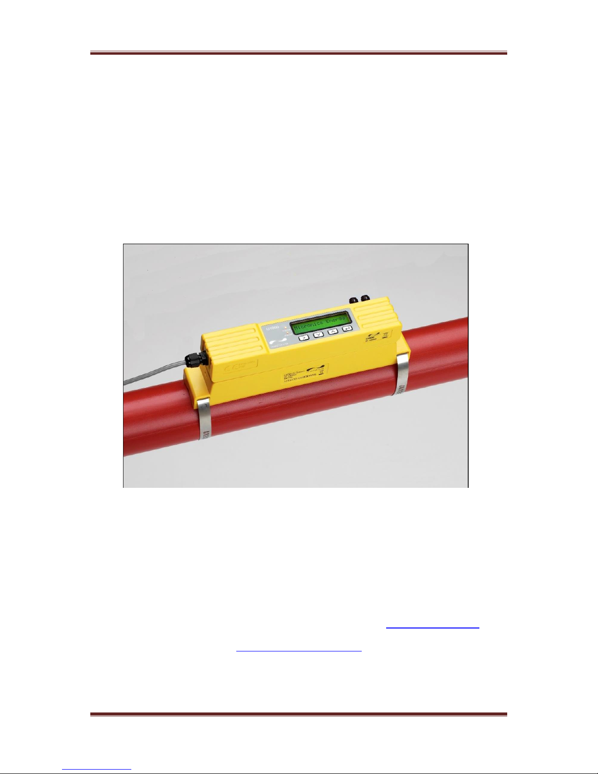
Micronics U1000-HM
Clamp On Ultrasonic Heat Meter
User Manual
Micronics Ltd, Knaves Beech Business Centre, Davies Way, Loudwater,
High Wycombe, Bucks HP10 9QR
Telephone: +44(0)1628 810456 Facsimile: +44(0)1628 531540 E-mail: sales@micronicsltd.co.uk
www.micronicsflowmeters.com
Page 2

Micronics U1000-HM User Manual
Issue 1.4 Page 2
Table of Contents
1 General Description ........................................................................................................................ 3
2 Quick start procedure ...................................................................................................................... 4
3 How does it work? ........................................................................................................................... 5
4 User interface .................................................................................................................................. 6
4.1 Key switches ........................................................................................................................... 6
5 Installing the U1000-HM .................................................................................................................. 7
5.1 Preparation .............................................................................................................................. 8
5.2 Sensor separation ................................................................................................................... 8
5.3 Attaching the U1000-HM to the pipe ..................................................................................... 10
5.4 Adaptors for small pipes ........................................................................................................ 11
5.5 Attaching the Temperature sensors ...................................................................................... 12
5.6 U1000-HM interface cable .................................................................................................... 13
5.7 Connecting the U1000-HM to the Supply ............................................................................. 13
5.8 Pulse Output connection ....................................................................................................... 13
5.9 Modbus connections ............................................................................................................. 13
5.10 Cable Screen......................................................................................................................... 14
6 Powering up for the first time ........................................................................................................ 14
6.1 How to enter the Pipe ID ....................................................................................................... 16
6.2 Pulse output .......................................................................................................................... 17
6.2.1 Volumetric mode ........................................................................................................... 17
6.2.2 Frequency mode ........................................................................................................... 17
6.2.3 Energy ........................................................................................................................... 17
6.2.4 Low Flow Alarm ............................................................................................................. 17
6.3 Modbus .................................................................................................................................. 18
7 Subsequent Power-ON Sequence ................................................................................................ 18
7.1 Information screens ............................................................................................................... 19
8 Password Controlled Menus ......................................................................................................... 20
8.1 General procedure for changing menu settings .................................................................... 20
8.1.1 Selection menus ............................................................................................................ 20
8.1.2 Data entry menus .......................................................................................................... 20
8.2 User Password controlled menu structure ............................................................................ 20
9 Diagnostics Menu .......................................................................................................................... 25
10 Relocation of guide rail .............................................................................................................. 26
11 Appendix I – U1000-HM Specification ...................................................................................... 27
12 Appendix II – Default values ..................................................................................................... 28
13 Appendix III – Error and Warning Messages ............................................................................ 29
14 Declaration of conformity ………………………….……………………………………………...……30
Page 3

Micronics U1000-HM User Manual
Issue 1.4 Page 3
1 General Description
Fixed installation, clamp-on heat meter
Easy to install
Requires the minimum of information to be entered by the user
Electronics and guide rail housings form an integral unit
Attached to the pipe using the supplied jubilee clips
Power to the unit is provided by an external 12 - 24V ac/dc power supply
Operates on steel, copper and plastic pipes with ID’s in the range 20mm (0.8”) to
110mm (4”) and a maximum wall thickness limit of 9mm for metal pipes and 10.5mm
for plastic.
Simple to install temperature sensors
Compact, rugged and reliable, the U1000-HM has been designed to provide sustained
performance in industrial environments
.
U1000 standard features include:
2 line x 16 character LCD with backlight
4-key keypad
Isolated pulse output
Universal guide rail for setting pre-assembled transducers
Dual PT type temperature sensors (standard cable length 5m)
Continuous signal monitoring
Password protected menu operation for secure use
Operates from external 12 to 24Vac or dc power supplies
Small pipe adaptors
Modbus RTU data output
Typical applications
Domestic, building services and industrial water systems heat metering.
Page 4

Micronics U1000-HM User Manual
Issue 1.4 Page 4
2 Quick start procedure
The following procedure details the steps required to set up the heat meter. See the
sections referred to if you are unsure about how to install the instrument.
1. Establish a suitable location for the flow meter on a straight length of pipe clear of
bends and valves or similar obstructions.(See Sections 5 and 5.1)
2. Determine the pipe internal diameter and material.
3. Either use the table in the manual, or power up the instrument to determine the correct
separation code. (See Sections 5.2 or 6)
4. Set the sensors to the correct separation by adjusting the sensor holding screws so
the sensor can slide in the slot. (See Section 5.2)
5. Select any adaptors needed for pipes with an outside diameter of less than 60mm,
inside diameter will typically be less than 50mm. (See Section 5.4)
6. Grease the sensors and mount the guide rail on the pipe using the banding provided,
then remove the sensor holding screws. (See Section 5.3)
7. Wire the electronics up to a 12 to 24V ac or dc power supply via the Blue and Brown
wires. (See Section 5.7)
8. Plug in the temperature sensors and place them touching each other. Wait for the
temperature readings to stabilize, indicated by no change for 30 seconds. Then zero
the temperature sensors. (See Section 5.5)
9. Attach the temperature sensors on to the pipe using the self-adhesive pads. Then use
the supplied banding to secure the sensor to the pipe. Don’t overtighten the banding.
The sensor must be in good thermal contact with the pipe and the leads must not be
under any strain. (See Section 5.5)
10. Plug in the flow sensors and clip the electronics assembly on to the guide rail.
11. Power up the instrument and check that flow and temperature readings can be
obtained(See Sections 6 and 7.1)
12. Once good readings have been obtained any further changes, such as selecting
different units, can be made via the User Menu. (See Section 8)
13. If the Modbus output is being used then the address of the instrument must be set
using the User Menu. (See Section 8) The default address is 1 and the Baud rate is
set to 38400; slower Baud rates can be set.
Page 5
Micronics U1000-HM User Manual
Issue 1.4 Page 5
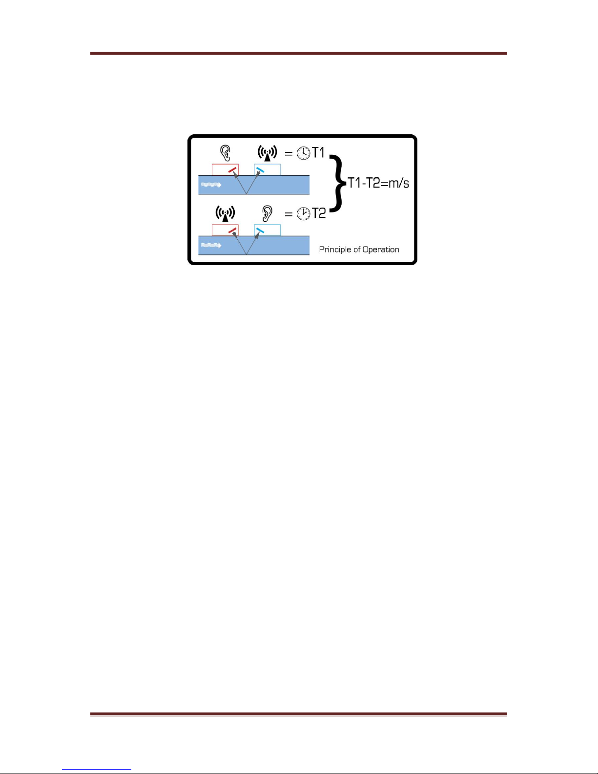
3 How does it work?
The U1000-HM is a clamp-on, ultrasonic flowmeter that uses a multiple slope transit time
algorithm to provide accurate flow measurements.
An ultrasonic beam of a given frequency is generated by applying a repetitive voltage pulse to
the transducer crystals. This transmission goes first from the Downstream transducer to the
Upstream transducer (red) as shown in the upper half of Figure 1. The transmission is then
made in the reverse direction, being sent from the Upstream transducer (red) to the
Downstream transducer (blue) as shown in the lower half of Figure1. The speed at which the
ultrasound is transmitted through the liquid is accelerated slightly by the velocity of the liquid
through the pipe. The subsequent time difference T1 – T2 is directly proportional to the liquid
flow velocity.
The two temperature sensors measure the difference in temperature between inlet and outlet
of the flow system being monitored. The temperature difference, in combination with the
volume of water that has flowed through the system, is then used to calculate the energy
transferred to or from the water.
Figure 1 Principle of Transit-Time operation
Page 6
Micronics U1000-HM User Manual
Issue 1.4 Page 6
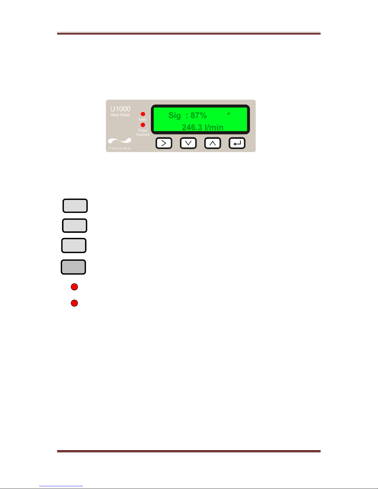
4 User interface
Figure 2 illustrates the U1000-HM user interface comprising:-
One 2 line x 16 character LCD with backlight
Four tactile key switches
Two LED’s
4.1 Key switches
kWh LED, this pulses each time an energy pulse is sent by the instrument.
Pulse Enabled LED is illuminated when the Pulse output is ON.
Figure 2 U1000-HM User Interface
Selection key. Allows the user to select between options on the
display.
Used to decrement the value of each digit in numeric entry fields.
Used to increment the value of each digit in numeric entry fields.
Used to enter the selection displayed or terminate the data entry.
Pressing this key can also take the user to a sub menu or to the
Flow Reading screen.
V
Sig : 87% *
246.3 l/min
Page 7
Micronics U1000-HM User Manual
Issue 1.4 Page 7
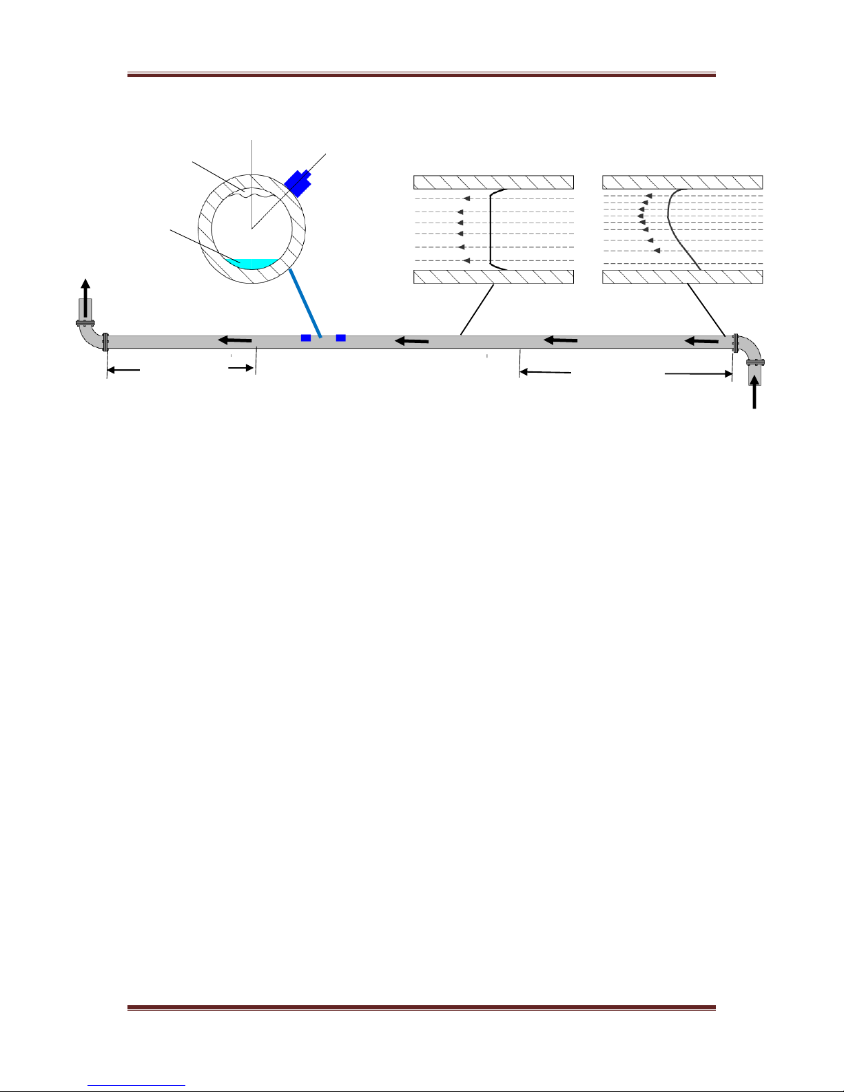
5 Installing the U1000-HM
Figure 3 Location of Transducers
For correct measurement of the energy transfer being measured by the instrument the flow
measurement needs to be made on the hot side of the system as near the hot temperature
sensor as possible.
In many applications an even flow velocity profile over a full 360° is unattainable due, for
example, to the presence of air turbulence at the top of the flow and possibly sludge at the
bottom of the pipe. Experience has shown that the most consistently accurate results are
achieved when the transducer guide rails are mounted at 45°with respect to the top of the
pipe.
The U1000-HM equipment expects a uniform flow profile, as a distorted flow will produce
unpredictable measurement errors. Flow profile distortions can result from upstream
disturbance such as bends, tees, valves, pumps and other similar obstructions. To ensure a
uniform profile the transducers must be mounted far enough away from any cause of distortion
such that it no longer has an effect.
To obtain the most accurate results the condition of both the liquid and the pipe must be
suitable to allow ultrasound transmission along the predetermined path. It is important that
liquid flows uniformly within the length of pipe being monitored, and that the flow profile is not
distorted by any upstream or downstream obstructions. This is best achieved by ensuring
there is a straight length of pipe upstream of the transducers of at least 20 times the pipe
diameter, and 10 times the pipe diameter on the downstream side, as shown in Figure 3. Flow
Measurements can be made on shorter lengths of straight pipe, down to 10 diameters
upstream and 5 diameters downstream, but when the transducers are mounted this close to
any obstruction the resulting errors can be unpredictable.
Key Point: Do not expect to obtain accurate results if the transducers are positioned close to
any obstruction that distorts the uniformity of the flow profile.
Micronics Ltd accepts no responsibility or liability if product has not been installed in
accordance with the installation instructions applicable to the product.
Possible Air
Possible
sludge
Guide
rail
Uniform Flow Profile
Distorted Flow Profile
Flow
Flow
Valid transducer location
20 x Diameter
10 x Diameter
Page 8
Micronics U1000-HM User Manual
Issue 1.4 Page 8
5.1 Preparation
1. Before attaching the transducers first ensure that the proposed location satisfies the
distance requirements shown in Figure 3 otherwise the resulting accuracy of the flow readings
may be affected. The unit is preconfigured for the application as follows :-
Instrument Type Heating or Chiller
Installation Flow or Return
Fluid Water or Water + 30% Ethylene Glycol
Flow and Return refer to the location of the Flow measurement relative to flow circuit.
Details of this configuration can be found in the Diagnostics menu (See Section 9)
2. Prepare the pipe by degreasing it and removing any loose material or flaking paint in order
to obtain the best possible surface. A smooth contact between pipe surface and the face of
the transducers is an important factor in achieving a good ultrasound signal strength and
therefore maximum accuracy.
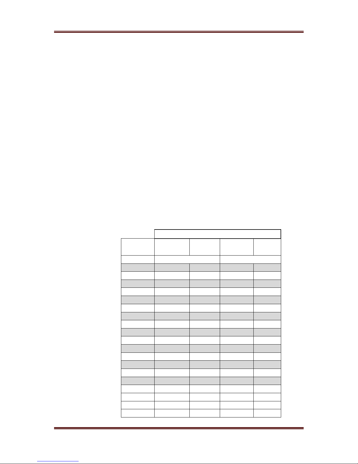
5.2 Sensor separation
The sensor must be positioned at the correct distance for the pipe size and type they will be
used on. The table below gives the typical separation code for a given pipe material and Inside
diameter, based on a 4mm wall thickness. If the wall thickness is significantly different from
this value then the separation may need to be one code higher or lower. The instrument
displays the required separation after the pipe internal diameter and material are entered.
Pipe ID range
Pipe material
Separation
Plastic and
Copper
Steel
Plastic and
Copper
Steel
Water
30% Glycol
B1
20-24
---
20-22
A2
25-30
20-22
23-27
20
C1
31-36
23-28
28-33
21-26
B2
37-42
29-34
34-38
27-31
A3
43-48
35-40
39-44
32-37
C2
49-54
41-46
45-50
38-42
B3
55-60
47-52
50-55
43-48
D2
61-65
53-58
56-61
49-53
C3
66-71
59-64
62-66
54-59
B4
72-77
65-70
67-72
60-64
D3
78-83
71-76
73-77
65-70
C4
84-89
77-82
78-83
71-76
E3
90-95
83-88
84-88
77-81
D4
96-101
89-94
89-94
82-87
F3
102-107
95-100
95-99
88-92
E4
108-110
101-106
100-105
93-98
D5
---
107-110
106-110
99-103
F4
---
---
---
104-109
E5
110
Figure 4 Separation Table
Page 9

Micronics U1000-HM User Manual
Issue 1.4 Page 9
The diagram below shows how to adjust the separation of the sensors
Figure 5 Separation Setting
Page 10
Micronics U1000-HM User Manual
Issue 1.4 Page 10
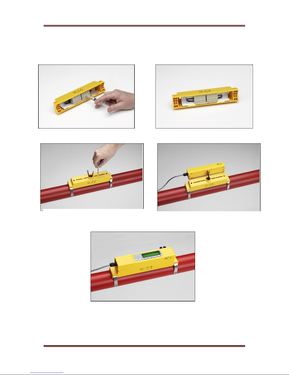
5.3 Attaching the U1000-HM to the pipe
Follow the five steps shown in Figure 6 below to attach the U1000-HM to the pipe.
Figure 6 simple steps to attaching the U1000-HM on the pipe
The locking screws and washers should be kept in case it is necessary to change the
location of the guide rail and sensors. See the relocation section for the procedure to do this.
The grease provided in the syringe is applied
to the centre of the sensors as shown above.
Clamp guide rail and sensor assembly to pipe,
using the supplied banding, and release
sensor locking screws.
Connect power and sensors to the electronics
assembly. Sensor leads can be connected
either way round.
Click electronic assembly onto guide rails and
sensor assembly
Page 11

Micronics U1000-HM User Manual
Issue 1.4 Page 11
5.4 Adaptors for small pipes
Figure 7 Pipe Adaptors
Guide rails for small pipes are supplied with adaptors. The diagrams above shows how these
are fitted around the pipe. The top pipe adaptor clips into the ends of the guide rail.
Less than 40mm outside diameter
40 to 60mm outside diameter
Greater than 60mm outside diameter
Page 12

Micronics U1000-HM User Manual
Issue 1.4 Page 12
5.5 Attaching the Temperature sensors
The temperature sensors must be located at the input and output of the system that is being
monitored. The area of pipe where they are to be attached must be free of grease and any
insulating material. It is recommended that any coating on the pipe is removed so that the
sensor has the best possible thermal contact with the pipe.
The sockets on the enclosure are marked Hot and Cold. This defines the location of the
temperature sensors on installations where heat is being extracted from the system.
To ensure an accurate temperature differential the following procedure should be used.
1. Plug in the sensors and place them touching each other.
2. Switch on the instrument and leave running for about 30 minutes.
3. Enter the password controlled menu (See Section 8) and scroll to the calibration submenu.
4. Press the enter key until the Zero Temp Offset screen is displayed.
5. Select Yes and press the Enter key to display the Attach Sensors screen.
6. Press the Enter key again and wait for instrument to return to the Zero Temp Offset
screen.
The instrument can now be turned off and the installation of the temperature sensors
completed.
The sensors have self-adhesive pads to locate them; they are then anchored using similar
banding to that used to mount the flow transducers. The banding must not be over tightened
or the sensors will be damaged. If the sensors are located under pipe lagging then ensure
this does not put a strain on the sensor cables. Tie down the sensor cables after the sensor
has been installed.
The temperature sensors must be used with the cable length supplied.
Extending or shortening the cables will negate the calibration of the
sensors.
Page 13

Micronics U1000-HM User Manual
Issue 1.4 Page 13
5.6 U1000-HM interface cable
The U1000-HM interface cable supplied is a 6-core cable and is shown in Figure 8.
The polarity of the wires is as follows:
The un-insulated wire is the connection to the screen of the cable and should be earthed for
full immunity to electrical noise.
5.7 Connecting the U1000-HM to the Supply
The U1000-HM will operate within the voltage range 12 - 24V ac/dc. Connect the external
power supply to the Brown and Blue wires of the six core cable. For full compliance with EMC
regulation a 12V supply is recommended for domestic and light industrial applications.
5.8 Pulse Output connection
The isolated pulse output is provided by a SPNO MOSFET Relay which has a maximum load
current of 500mA and maximum load voltage of 48V AC. The relay also provides 2500V
isolation, between the sensor’s electronics and the outside world.
The pulse output is available at the White and Green wires. Electrically this is a volt, or
potential, free contact closure.
5.9 Modbus connections
The Red and Black wires provide an optional Modbus interface over a twisted pair cable.
The physical connection is RS485.
Power
Pulse
Figure 8. U1000-HM Interface Cable
12/24V Input
12/24V Return
Pulse Output
Pulse Return
Un-insulated screen
+ Modbus
- interface
Page 14

Micronics U1000-HM User Manual
Issue 1.4 Page 14
5.10 Cable Screen
For full immunity to electrical interference the screen of the cable should be connected to
Earth.
6 Powering up for the first time
Powering up for the first time will initiate the sequence shown in Figure 9:
See below
If the heatmeter has been factory set for user selection of the application, the following
additional screens will be displayed.
Select the option required and press the
Figure 9 initial power up screens
key
Page 15

Micronics U1000-HM User Manual
Issue 1.4 Page 15
1. The Micronics start up screen is displayed for 5 seconds
2. The user enters the pipe ID and selects the material (refer to section 6.1)
3. On pressing enter in response to the Set Separation screen the U1000-HM then checks for
a valid signal.
4. If a valid signal is found, signal strength and flow magnitude are displayed. The signal
strength should be at least 40% for reliable operation. The direction of flow when powered up
will be taken to be the positive flow direction. The pulse output will relate to the flow in this
direction. If the flow is reversed then the flow rate will still be displayed but the activity indication
will change from an asterisk to an exclamation mark and no pulses will be generated.
If a valid flow reading is obtained then after a few seconds the Total Energy screen will be
displayed.
If the flow value is displayed as “------“ this indicates that there is no usable signal from
sensors.
The cause of this could be incorrect pipe data, no grease on the sensors, sensor not in
contact with the pipe or very poor surface conditions on the inside of the pipe.
Please note:
There is little available data on the specific heat capacity (K factor) for water
glycol mixes and there is no practical method of determining the percentage of
glycol in a system or the type of glycol in use. The calculations are based on a
Water/Ethylene glycol mix of 30%.
In practical terms the results should not be considered more than an
approximation as:
The fluid speed of sound can vary between 1480ms and 1578ms
No temperature compensation curve is available for water/glycol mixes,
The percentage of Glycol can change the specific heat capacity from 1.00 to 1.6
J/M3 * K
The type of glycol added can change the specific heat capacity and fluid speed
of sound considerably.
The Factory enabled user set up of the aplication relies on the installer to set
the correct operating parameters, a considerable variation in results can be
obtained from miss-set units.
Page 16

Micronics U1000-HM User Manual
Issue 1.4 Page 16
6.1 How to enter the Pipe ID
Figure 10 shows the Enter Pipe ID screen after an initial power up.
Initially, the hundreds unit (050.0) will blink.
Press the
key to increment the hundreds digit (050.0) in the sequence 0, 1.
Press once to increment digit, or hold key down to automatically
toggle between 0 and 1.
Press the
key to decrement the hundreds digit in the sequence 1, 0. Press
once to decrement digit, or hold key down to automatically toggle
between 1 and 0.
Press the
key to move to the tens digit (050.0). The tens digit should now blink.
Increment the tens digit in the sequence 0,1,2,3,4,5,6,7,8,9,0 using
the key. Press once to increment digit or hold down to scroll
through the numeric sequence. Decrement the tens digit in the
sequence 9,8,7,6,5,4,3,2,1,0,9 using the key. Press once to
increment digit or hold down to scroll through the numeric sequence.
Press the
key to move to the units digit (050.0). The units digit should now
blink. Increment or decrement the units digit in an identical manner
to the tens digit described above.
Press the
key to move to the decimal digit (050.0). The decimal digit should
now blink. Increment or decrement the decimal digit in an identical
manner to the tens digit described above.
Press
the
Use
key to enter the Pipe ID numerical value, and move to the next
screen
and
keys to scroll through the pipe materials and
then press
To select the material and complete the
setup procedure.
V
Figure 10 Enter Pipe ID Screen (Metric)
V
Enter Pipe ID:
050.00 mm
Pipe material
Steel
V
Page 17

Micronics U1000-HM User Manual
Issue 1.4 Page 17
If any of the parameters need to be changed from the default values, for example different
units are required, then the menu system must be activated via the password (see section 8).
6.2 Pulse output
Pulse output can be set up to operate in four modes, namely volumetric, frequency, energy or
Low Flow Alarm.
6.2.1 Volumetric mode
In Volumetric mode, each pulse output represents a measured volume of 10 litres (default
value). In Volumetric mode, with the Vol per Pulse set to 1 and the pulse width set to 25ms,
the maximum number of pulses that can be output (without storage) is 1/(0.025*2) = 20 pulses
per second. If the flow rate in the pipe is such that more than 20 pulses per second are
generated, a Pulse Overflow error may eventually occur if the stored number of pulses
exceeds 1000. To avoid this, set the Vol per Pulse to 10 litres, or reduce the Pulse Width
value.
6.2.2 Frequency mode
In Frequency mode, the pulse output frequency is proportional to the flow rate within a
specified frequency range of 0 – 200Hz. The flow units on the frequency output are fixed as
litres per second. The conversion factors from imperial units are:-
US gallons/minute multiply by 0.06309
US gallons/hour multiply by 0.00105
Imperial gallons/minute multiply by 0.07577
Imperial gallons/hour multiply by 0.001263
6.2.3 Energy
In Energy mode, each pulse represents an amount of energy e.g. 1kWh. The same limitation
on maximum pulse rate applies as detailed in the Volumetric Mode. Again a larger unit of
energy per pulse or a smaller pulse width may be required.
6.2.4 Low Flow Alarm
This mode will turn on the pulse output (low resistance path) when the flow rate goes below
the value set in the parameters for this mode. There is a 10% hysteresis on the switching of
the output. Once turned on the flow rate must rise by 10% more than the set value to turn it
off again.
Page 18

Micronics U1000-HM User Manual
Issue 1.4 Page 18
6.3 Modbus
The Modbus RTU interface is configured via the Modbus sub menu in the password controlled
menu.
The Baud rate can be selected in the range 1200 to 38400.
The address can be set in the range 1 to 254.
The following registers can be read. The instrument responds to the “read holding registers”
(CMD 03).
If the flow reading is invalid then the flow value will be zero.
If a temperature sensor goes out of range then the value will go to -11°C.
Both of these faults will clear the status bit.
Modbus
Register
U1000
Register
Description
Notes
40001
0
Device ID
0xac for the U1000-HM
40002
1
Status
0= fault, 1= system ok
40003
2
Hot or Cold
0x04 for hot 0x0c for cold
40004
3
Serial number
Integer value
40005
4-5
Firmware rev
Integer value
40007
6-7
Flow m3/sec
2 registers IEE754 floating Point
40009
8-9
Flow m3/hr
2 registers IEE754 floating Point
40011
10-11
Power kW
2 registers IEE754 floating Point
40013
12-13
Energy kWh
2 registers IEE754 floating Point
40015
14-15
Hot temperature
2 registers IEE754 floating Point
40017
16-17
Cold temperature
2 registers IEE754 floating Point
40019
18-19
Delta temperature
2 registers IEE754 floating Point
40021
20-21
Flow Total m3
2 registers IEE754 floating Point
40023
22
Instrument Units
0=Metric 1=Imperial
40024
23
Instrument Gain
Integer value
40025
24
Instrument Switch
Integer value
40026
25
Instrument Signal
Integer value
40027
26-27
Instrument Flow Time (ns)
2 registers IEE754 floating Point
40029
28-29
Instrument ETA (ns)
2 registers IEE754 floating Point
40031
30-31
Instrument ATA (ns)
2 registers IEE754 floating Point
Figure 11 Modbus registers
7 Subsequent Power-ON Sequence
If the power supply is cycled OFF then ON after the pipe data has been entered, all subsequent
start-ups will use the same configuration as was previously entered. If the configuration needs
to be changed for any reason, the user can make use of the password-controlled menu as
described in section 8.
Page 19

Micronics U1000-HM User Manual
Issue 1.4 Page 19
7.1 Information screens
Total Flow
1012.23 litres
Instant Power:
000.00 kW
Temperature dT:
H 30.0 C 23.0: 7.0
Sig 80% *
100 l/min
Total Energy:
00.00 kWh
v
v
v
v
Λ
Λ
Λ Λ Λ
v
The system will initially display the Flow Reading screen. If there are valid
flow and temperature readings, then after a few seconds the Total Energy
screen will be displayed.
If the flow reading is invalid then the Flow screen will be displayed.
Similarly the Temperature screen will be displayed if a reading goes out
of range.
This screen is not shown if Select
Totals is set to Off.
Diagnostics
>
Figure 12 information screens
Page 20

Micronics U1000-HM User Manual
Issue 1.4 Page 20
8 Password Controlled Menus
The password controlled menu allows the user some flexibility to change the default settings:
User Password (71360):
Change the dimensions from mm to inches or vice-versa.
Change from Flow to Velocity Measurement
Change the system units litres/m3 or Impgal/USgal
Change the flow units l/s, l/min or gal/s, gal/min or USgals/s, USgals/min
Change the Pulse Output type
Change the Pulse output parameters
Change the energy units
8.1 General procedure for changing menu settings
8.1.1 Selection menus
When a password controlled menu is selected the procedure for changing the default setting
is the same for all menus. For example, consider the Flow Units menu shown in Figure 13.
The default value ‘l/min’ will blink to indicate that this is the current setting. To change to ‘l/s’,
press the key. Now the ‘l/s’ units will blink to indicate that this is now the selected units.
Press the key to confirm the change.
The only exceptions to this are in the Pulse output menu, where the and keys
are used to scroll through the options Volume/Frequency/Energy, and the Energy per Pulse
values.
8.1.2 Data entry menus
Menus containing a numeric value can be altered using the same method used to input the
pipe ID.
8.2 User Password controlled menu structure
While in any of the information screens pressing the key will access the user password
menu. Enter 71360 using the procedure explained in section 6.1 to enter the password.
Figure 13 Flow Units menu
Flow Units:
l/min | l/s
Page 21

Micronics U1000-HM User Manual
Issue 1.4 Page 21
The flow chart shown in Fig.14 shows the user password menu structure. To skip over any
menu item that should remain unchanged, simply press the key.
Figure 14 Main Menu
Sig: 87% *
246.3 l/min
Enter Password:
*****
71360 MENU
Invalid & OR No
input for 10 seconds
User Menu:
Pulse Output
User Menu:
Calibration
User Menu:
Setup
User Menu:
Totals
Checking Signals
******
Sig: 87% *
246.3 l/min
Setup Menu
Totaliser Menu
Pulse Output Menu
User Menu:
Exit
v
v
v
v
Calibration Menu
v
User Menu:
Modbus Setup
v
Modbus Menu
Page 22

Micronics U1000-HM User Manual
Issue 1.4 Page 22
Figure 15 Setup Menu
If “inches” is selected then the temperatures will be displayed in °F and the energy values will
be in BTUs.
Select Dimensions:
mm | inches
Enter Pipe ID:
050.0 mm
Enter Pipe ID:
2.000 inches
Select Reading:
Flow | Vel
Select Reading:
Flow | Vel
System Units:
litres | m3
System Units:
Impgal | USgal
Flow Units
m3/min | m3/h
Flow Units
l/min | l/s
Flow Units
gal/min | gal/h
Flow Units
USgal/min | USgal/h
Range 20 – 110mm
050.0 mm
SETUP MENU
Inches &
Invalid
&
mm &
Invalid &
Valid &
Valid &
Vel & (m/s)
m3 &
Flow &
Litres &
Valid &
Flow &
Impgal &
USgal &
Vel &
(ft/s)
Range 0.79 – 4.33
2.000 inches
Select Material:
Steel
Set Separation:
B 3
Instrument Type
Heating|Chiller
Instrument side
Return|Flow
Instrument Fluid
Glycol|Water
and User installation
setup
Page 23

Micronics U1000-HM User Manual
Issue 1.4 Page 23
Figure 16 Pulse output and Modbus menu
Select Pulse:
ON | OFF
Volume per Pulse:
10.0 l
Pulse Width
25 ms
PULSE OUTPUT MENU
Valid &
On &
Volume &
Max Pulse Freq:
200
Max Flow @ Freq:
9999.0 l/s
Valid &
Valid &
Test mode press V or Λ to
generate a 20ms pulse
Invalid &
Freq &
Pulse Type:
Energy
Range 3 - 99
25 ms
Range 1 – 200
200
Invalid &
Valid &
Off &
Energy Pulse
10 kWh
Energy &
Enter Level:
00500.0
Low Flowl Alarm
Modbus Address:
103
Modbus Baud:
38400
MODBUS MENU
Range 1.0 to 254.0
103
Invalid &
valid &
Valid &
Page 24

Micronics U1000-HM User Manual
Issue 1.4 Page 24
Figure 17 Calibration and totaliser Menu
Damping Time [s]:
20
Zero Cut-off:
0.10 m/s
Zero Offset
0.000 l/min
Range 0.00 – 0.50
0.10 m/s
Done
Zero Offset:
Averaging…9
^ To Clear
V To Set
Valid &
Invalid &
Calibrat. Factor:
1.000
Range 0.500–1.500
1.000
CALIBRATION MENU
Invalid &
Valid &
Zero Temp Offset
YES|NO
No &
Calibrate #1
H00.0/C00.0: 0.00
Yes &
Attach Sensors:
Press Enter
Done
Select Totals
ON|OFF
On &
Reset Total
NO |YES
Off &
TOTALISER MENU
Page 25

Micronics U1000-HM User Manual
Issue 1.4 Page 25
9 Diagnostics Menu
The diagnostics menu provides some additional information about the heat meter and its
setup. The menu can be accessed by pressing the key from flow reading screen. The
menu shown below describes the various diagnostics items.
DIAGNOSTICS MENU
The Estimated TA (Time of Arrival) and Actual TA show
the theoretical and measured transit times. These values
should be within several per cent of each other. If the
actual value is displayed as 9999.99 then a usable signal
could not be detected.
The gain on line one is an indicator of the signal strength.
A good signal should have a gain of between 600 to 970.
The number in parentheses is the switch setting and
should be x1 or x10. Gains of X100 show that the
received signal is too small to be used.
The second line shows the current time differential
between the upstream and downstream signals.
The unit’s software version is shown on line 1.
Line 2 shows the unit’s serial number.
This screen will be displayed if the Pulse output is on,
and show data related to the mode of operation. This
includes a live display of the Frequency output.
Press
To exit the Diagnostics
N. B. The key board is less responsive in the
Diagnostics Menu and longer key presses are
required.
Sig: 87% *
246.3 l/min
Est.TA 85.64
Act .TA 86.77
Gain 845 (x1)
DT 125 ns
Rev: 05.00.001
S/N:112547
Pulse Frequency
124
v
v
v
v
Pipe Material
Steel
v
The selected pipe material.
The required sensor separation.
Set Separation
B 2
v
v
Page 26

Micronics U1000-HM User Manual
Issue 1.4 Page 26
10 Relocation of guide rail
If it is necessary to relocate the guide rail and sensor assembly use the following procedure.
1. Remove complete assembly from the pipe.
2. Insert a small screwdriver in the hole at the end of the guide rail moulding and lever
up the clip holding the electronics assembly by pressing down on the screwdriver as
shown below.
3. Repeat 2 on the other end and then pull off the electronics unit.
Figure 19
4. Disconnect the sensors
5. Remove the original grease from the sensors
6. Push the sensor blocks into the guide rail so that the washers and locking screws
can be refitted.
7. Place a bead of grease down the centre of the sensor block using the syringe
provided. See illustration on fitting the guide rail to the pipe for recommended bead
size.
8. Follow the original procedure for installing the guide rail on the pipe.
Figure 18 Diagnostics Menu
Instrument Type:
Heating
Installation:
Flow Side
Fluid Type:
Water
Factory set type of energy exchange, either Heating or
Chiller.
Factory set location of the flow measurement, either Flow
or Return.
Factory set fluid.
Page 27

Micronics U1000-HM User Manual
Issue 1.4 Page 27
11 Appendix I – U1000-HM Specification
Table 1 lists the U1000-HM Product Specification.
General
Measuring Technique
Transit time
Measurement channels
1
Timing Resolution
±50ps
Turn down ratio
200:1
Flow velocity range
0.1 to 10m/s bidirectional
Applicable Fluid types
Clean water with < 3% by volume of particulate content, or up to
30% ethylene glycol
Accuracy
±3% of flow reading for flow rate >0.3m/s
Repeatability
±0.5% of measured value
Selectable units
Velocity: m/s, ft/s
Flow Rate: l/s, l/min, gal/s, gal/min, USgal/s, USgal/min,
m3/min, m3/h
Volume: litres, m3, gals, USgals
Energy : kWh, MWh, kBTU, MBTU
Totaliser
8 digits with roll over to zero
Languages supported
English only
Power input
12 – 24V ac or dc
Power consumption
7VA maximum
Cable
5m screened 6 core
Pulse Output
Output
Opto-isolated MOSFET volt free normally open contact.
Isolation
2500V
Pulse width
Default value 25ms; programmable range 3 – 99ms
Pulse repetition rate
Up to 166 pulses/sec (depending on pulse width)
Frequency mode
200 Hz maximum
Maximum load voltage/current
48V AC / 500mA
Temperature sensors
Type
PT100 Class B 4 wire
Range
0 to 85°C (32 to 185°F)
Resolution
0.1 °C (0.18°F)
Cable length
5m (standard)
Modbus
Format
RTU
Baud rate
1200 to 38400
Standards
PI–MBUS–300 Rev. J
Physical connection
RS485
Enclosure
Material
Plastic Polycarbonate
Fixing
Pipe mountable
Degree of Protection
IP54
Flammability Rating
UL94 V-0
Dimensions
250mm x 48mm x 90mm (electronics + guide rail)
Weight
0.5kg
Page 28

Micronics U1000-HM User Manual
Issue 1.4 Page 28
Environmental
Pipe temperature
0°C to 85°C
Operating temperature
(Electronics)
0°C to 50°C
Storage temperature
-10°C to 60°C
Humidity
90% RH at 50°C Max
Display
LCD
2 line x 16 characters
Viewing angle
Min 30°, Max 40°
Active area
83mm (W) x 18.6mm(H)
Keypad
Format
4 key tactile feedback membrane keypad
12 Appendix II – Default values
The settings will be configured at the factory for either metric or imperial units. Table 2 lists
the metric default values.
Table 2 System Default Values
Parameter
Default Value
Dimensions
mm
Flow Rate
l/min
Pipe size
50 (mm)
Pulse Output
On
Energy per Pulse
1kWh
Pulse Width
25ms
Damping
20 seconds
Calibration Factor
1.000
Zero Cut-off
0.10m/s
Zero Offset
0.000l/min
Modbus address
1
Baud rate
38400
Table 3 lists the default values when Imperial dimensions are selected.
Table 3 System Default Values
Parameter
Default Value
Dimensions
inches
Flow Rate
USgal/min
Pipe size
2 (inches)
Pulse Output
On
Energy per Pulse
1 kBTU
Pulse Width
25ms
Damping
20 seconds
Calibration Factor
1.000
Zero Cut-off
0.10m/s
Zero Offset
0.000gal/min
Modbus address
1
Baud rate
38400
Page 29

Micronics U1000-HM User Manual
Issue 1.4 Page 29
13 Appendix III – Error and Warning Messages
System errors
There are three possible ‘System Error’ messages that can be displayed. These are:
1. Poor Signal. The unit is unable to detect a signal from one or both transducers. If this
message persists the sensors will need to be relocated.
2. Pulse Overflow. The value for the ‘Vol per pulse’ is set too low, or the output pulse
width is too wide. Increase the Vol per Pulse setting in the password-controlled menu.
3. No BBME: This indicates a unit failure. Reset the unit by turning the power on and off.
Contact your supplier if the problem persists.
Flow and temperature errors
If the flow reading is lost or goes negative then the Flow Reading screen will be displayed to
indicate the nature of the fault. A signal strength of less than 40% indicates poor set up of the
instrument, and the installation should be checked or possibly moved to a different site. A
negative flow is indicated by an”!” being displayed on the top line instead of a “*”.
If the temperature difference exceeds the upper limit or the reading from either of the sensors
is lost, then the Temperature Values screen will be displayed.
Warnings
These generally advise the user that the data entered is out of the specified range.
1. When an invalid Pipe ID is entered, the warning message shown below is displayed,
prompting the user to enter a value between 20 and 110mm.
2. When programming a Frequency Pulse output the frequency is limited to the range 1 to 200
Hz. If an invalid value is entered then the following warning message is displayed.
Range 20 – 110mm
0.000 mm
Range 1 - 200
200
Page 30

Micronics U1000-HM User Manual
Issue 1.4 Page 30
3. When programming a Volume Pulse output the pulse width is limited to the range 3 to 99ms.
If an invalid value is entered then the following warning message is displayed.
4. When programming the Zero Cut-off this is limited to the range 0.000 to 0.500. If an invalid
value is entered then the following warning message is displayed.
5. When programming the Calibration Factor this is limited to the range 0.5 to 1.5. If an invalid
value is entered then the following warning message is displayed.
6. If an attempt is made to zero the offset between the temperature sensors, and the difference
in temperature is too large then this error message will be displayed.
Ensure the temperature sensors are correctly plugged in and are both at the same
temperature.
Range 3 - 99
0000.0
Range 0.00 – 0.500
0000.0
Range 0.500 – 1.500
0000.0
Calibrate Error
Press Enter
Page 31

Micronics U1000-HM User Manual
Issue 1.4 Page 31
Registered Office: Micronics Limited, Knaves Beech Business Centre, Davies Way, Loudwater, Buckinghamshire, HP10 9QR
Web site www.micronicsflowmeters.com Tel: +44 (1628) 810456 Fax: +44 (1628) 531540
Directors E.J. Farnon, M.A. Farnon
Registration No. 1289680 V.A.T Registration No. 303 6190 91
 Loading...