

Page 1

D5CUB PCI/ISA
System Board Manual
Document Number: 06-00287-02, Rev. B
June 1996
221 Warren Ave., Fremont, CA 94539-7085
Page 2

Copyright Notices
Copyright 1996 Micronics Computers, Inc. The information contained
2
in the D5CUB PCI/ISA system board manual has been carefully checked
and is believed to be accurate. Micronics assumes no responsibility for any
inaccuracies that may be contained in this document. Micronics makes no
commitments to update or to keep the information in this manual at a
current level when changes are made to the product.
Micronics reserves the right to make improvements to this document
and/or product at any time and without notice. All Rights Reserved. No
part of this document may be photocopied, reproduced, translated, or
reduced to any medium or machine form without prior, written consent
from Micronics.
Portions of the Manual
Portions of this manual were copied (with permission) from Award
Software Inc. and Micro Computer Systems, Inc. All rights reserved.
Trademarks
Award Modular BIOS is a registered trademark of Award Software Inc.
IBM is a registered trademark of International Business Machines. Microsoft and Windows are registered trademarks of Microsoft Corporation.
Intel and PCI are registered trademarks of Intel Corporation. All other
product names mentioned herein are used for identification purposes only
and may be the trademarks of their respective companies.
D5CUB System Board Manual
Page 3

Table of Contents
Introduction 5
Features 6
Software Compatibility 7
Before You Begin 8
Section 1 - Quick Installation 9
Installing the D5CUB 9
Section 2 - Configuring the D5CUB 13
Static Electricity 13
Office Environment 13
D5CUB System Board 14
Jumper Settings 15
Section 3 - Installing the D5CUB 21
Introduction 21
System Memory Support 21
Installing the D5CUB 22
Tools Required 22
Equipment Required 22
System Memory 23
SIMMs Supported 23
Upgrading Rules 23
Mixing EDO and FPM Memory 24
Memory Configurations 25
Installing the SIMMs 26
Removing SIMMs 26
Installing a CPU 27
Installing a PCI Peripheral Card 28
Installing an ISA Peripheral Card 29
D5CUB System Board Manual
1
Page 4

Installing a CD-ROM Drive 30
Installing the Sound Interface Card 31
Connecting Sound Devices 32
Section 4 - The BIOS Setup Utility 35
Configuration 35
Initial Bootup 35
Setup 35
Running the Setup Procedure 37
Standard CMOS Setup 38
BIOS Features Setup 40
Chipset Features Setup 43
Power Management Setup 44
PnP/PCI Configuration Setup 46
Load BIOS Defaults 48
Load Setup Defaults 48
Integrated Peripherals 49
Supervisor Password 51
User Password 51
IDE HDD Auto Detection 52
HDD Low Level Format 53
Save and Exit Setup 54
Exit Without Saving 54
Section 5 - Installing Sound Device Drivers 55
About Device Drivers 55
Installing the Sound Drivers 56
Appendix A - Technical Information 57
Specifications 57
Environmental Specifications 58
Temperature Range 58
2
D5CUB System Board Manual
Page 5

Relative Humidity 58
Battery Disposal 59
Technical Support 60
Online Services 61
Appendix B - Post Messages 63
Appendix C - Hard Disk Drive Types 65
Appendix D - Updating the System BIOS 67
Appendix E - Compatibility 69
Limited Warranty 72
Non-Warranty Service 73
FCC Statement 74
Declaration of Conformity 75
Index 76
D5CUB System Board Manual
3
Page 6

List of Figures
Figure 1.1: Power-Up Screen 10
Figure 2.1: D5CUB System Board 14
Figure 3.1: Installing a 72-Pin SIMM 26
Figure 3.2: Installing a CPU 28
Figure 3.3: Installing an ISA Peripheral Card 29
Figure 3.4: Connecting the Sound Interface Card 32
Figure 4.1: Power-Up Screen 36
Figure 4.2: Main CMOS Setup Screen 37
Figure 4.3: Standard CMOS Setup Screen 38
Figure 4.4: BIOS Features Setup Screen 40
Figure 4.5: Chipset Features Setup Screen 43
Figure 4.6: Power Management Screen 44
Figure 4.7: PnP/PCI Configuration Screen 46
Figure 4.8: Integrated Peripherals Screen 49
Figure 4.9: IDE HDD Auto Detection Screen 52
Figure 4.10: HDD Low Level Format Screen 53
List of Tables
Table 2.1: System Speed Selection (Intel) 15
Table 2.2: System Speed Selection (Cyrix) 15
Table 2.3: Power Supply Voltage Selection 16
Table 2.4: Pentium CPU Type Selection 16
Table 2.5: TAG SRAM Type Selection 16
Table 2.6: Multi I/O Chipset Selection 17
Table 2.7: Sound Interface Selection 17
Table 2.8: CPU Internal Cache Selection 17
Table 2.9: Clear CMOS Memory Selection 18
Table 2.10: Clock Ratio Selection 18
Table 2.11: Jumper Settings & Functions 19
Table 2.12: Connector Settings and Functions 20
Table 3.1: Memory Configurations 25
4
D5CUB System Board Manual
Page 7

Introduction
Thank you for choosing the D5CUB system board. The
D5CUB provides the latest enhancements in systemboard technology for high-performance desktops.
Based on the Intel 430HX PCIset, the D5CUB provides
enhanced PCI throughput and performance for today’s
demanding applications. The onboard voltage regulator
permits the use of Intel’s fastest processors and the Cyrix
6x86 processor.
The D5CUB comes with many features. These include
support for Fast Page Mode (FPM) and Extended Data
Out (EDO) memory, Error Checking and Correction
(ECC), pipelined-burst level 2 cache, the Award Plug
and Play BIOS and an optional feature for integrated 16bit sound.
Micronics builds all products to exacting standards, using
the highest quality components available. We are proud
to provide this system board and believe you will be
pleased with your purchase.
D5CUB System Board Manual
5
Page 8

Features
The D5CUB includes the following features:
Single ZIF socket 7 xxxx xxxx xxxx xxxx xxxx xxxxxxxx
Supports Intel 75 - 200 MHz Pentium and Pentium
iiiiiOverdrive processors xxxx xxxx xxxx xxxx xxxx
Supports Cyrix 6x86 100-133MHz processorsxxxx xxxx
VRE support
Intel 430HX PCIset
Intel PIIX 3
SMC 669/UMC8669/ALI M5113 I/O chip
Three 32-bit PCI slots xxxx xxxx xxxx xxxx xxxx xxxx
Two 16-bit ISA slots xxxx xxxx xxxx xxxx xxxx iiiii
One shared PCI/ISA slot xxxx xxxx xxxx xxxx xxxx
16 KB on-chip Level 1 write-back cache xxxx xxxx iii
Up to 512K pipelined burst external Level 2 cache
Support for up to 256MB of onboard system memory
Four 32/36-bit, 72-pin, double-sided SIMM sockets to
accommodate: xxxx xxxx xxxx xxxx xxxxxx xxxx iiiii
1MB x 32/36 (4MB)xx4MB x 32/36 (16MB)xxxx iiiii
2MB x 32/36 (8MB)xx8MB x 32/36 (32MB)xxxx
16 MB x 32/36 (64 MB)xxxx xxxx xxxx
Supports EDO memory
ECC support via chipset
PCI local bus IDE xxxx xxxx xxxx xxxx xxxx xxxx xxxx
Mode 4 Enhanced IDE with Bus Mastering xxxx xxxx
Two resident 40-pin IDE connectors
iiiii(Primary and Secondary IDE) xxxx xxxx xxxx xxxx
Auto detection of add-in IDE interface boards xxxx
Multiple-sector transfer support
Floppy controller for two floppy drives (supports 2.88MB,
1.44MB, 1.2MB, 720K, and/or 360K floppy drives)
Auto detection of add-in floppy controllers
D5CUB System Board Manual6
Page 9

Two onboard 16550-compatible serial ports xxxx xxxx
One onboard parallel port with ECP and EPP supportxx
Field upgradeable Award BIOSxxxx xxxx
PCI auto configuration xxxx xxxx xxxx xxxx xxxx
Plug and Play ready xxxx xxxx xxxx xxxx xxxx xxxx
Auto detection of memory sizexxxx xxxx xxxx xxxx
Auto detection and display of ECC and EDO memoryx
Auto configuration of IDE hard disk types
ESS 1788F Soundxxxx xxxx xxxx xxxx xxxx xxxxxxx
Sound Blaster-compatible 16-bit Stereo xxxx xxxx
Input/Output, Game and MIDI ports xxxx xxxx xxxx
iiiii(sound support is optional)
Software Compatibility
The D5CUB system board has been thoroughly tested for
compatibility with a variety of operating systems and environments, including:
Windows 95 and Windows NT
OS/2 Warp
SCO UNIX and Open Desktop
Novell Netware
MS-DOS 5.0 and 6.2
PC-DOS
Solaris
D5CUB System Board Manual
7
Page 10
Before You Begin
This manual will familiarize you with the features, installation and use of your D5CUB. There are several symbols and
conventions used throughout this manual to help draw your
attention to a feature or to focus on important information:
When you see the Magnifying Glass, it refers
to something you should take a closer look at
before proceeding further.
When you see the Exclamation Mark, it gives
important information on avoiding damage.
Common Names
DRAM Dynamic Random Access Memory
ECC Error Checking and Correction
ECP Enhanced Communications Port
EDO Extended Data Out
FPM Fast Page Mode
IDE Integrated Drive Electronics
PCI Peripheral Component Interconnect
SIMM Single Inline Memory Module
VR Voltage Regulated
VRE Voltage Regulated Extension
8
D5CUB System Board Manual
Page 11

Section
1
Section 1: Quick Installation
Quick Installation
We know that many experienced people prefer to read as
little of the documentation as possible. If this sounds like
you, here’s the short form to get up and running quickly.
Installing the D5CUB
1. Make backup copies of your installation and configuration diskettes.
2. Ground yourself to prevent damaging static discharge by using an anti-static wrist or ankle strap, or
touch a safely grounded metal object.
3. Remove the D5CUB from its packaging.
4. Configure and verify the system board’s jumper settings (refer to Jumper Settings in Section 2).
5. Install the CPU and the system memory.
6. Install the system board in the chassis and make all
necessary case connections.
7. Install any ISA and PCI add-on peripherals.
8. Connect any optional devices.
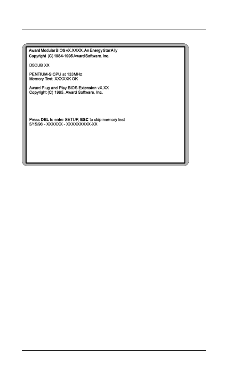
9. Turn the computer on and press the <DEL> key
when you see the screen shown in Figure 1.1.
D5CUB System Board Manual
9
Page 12
Section 1: Quick Installation
Figure 1.1: Power-Up Screen
10. If necessary, use the arrow keys to move the highlight
to STANDARD CMOS SETUP and press <Enter>.
11. Set the time and date.
12. If necessary, adjust the settings for the floppy drive(s)
and hard drive(s) to match your configuration. If you
are installing one or more IDE drives, the BIOS automatically configures your drive(s) for you when the
setting in the Type column is Auto (the default setting). See Chapter 4 for additional information and
additional instructions.
13. Verify that the floppy drive type(s) shown for Drive A
(and Drive B, if installed) are correct. If necessary
change the setting(s) for the floppy drive(s) using the
<Pg Up> and/or <Pg Dn> keys or the <+> and
<–> keys.
10
D5CUB System Board Manual
Page 13

Section 1: Quick Installation
14. Verify that the amounts of memory shown in the
Standard CMOS Setup screen correctly reflect the
amount of RAM installed in your system.
15. Press <ESC> to return to the main setup menu.
16. Use the arrow keys to move the highlight to any of
the other setup options in the main menu that
contain settings you want to review or change (for
information on the various setup options in the main
menu, see Chapter 4). When you are finished, press
<F10> to select Save & Exit Setup. You are now
finished with the BIOS configuration.
17. If you are using the sound option, install the sound
controller device drivers.
18. If you have installed a CD-ROM drive, install its
device drivers.
D5CUB System Board Manual
11
Page 14

Section 1: Quick Installation
12
D5CUB System Board Manual
Page 15

Section 2: Configuring the D5CUB
Section
2
Configuring the D5CUB
Although the D5CUB system board is packaged in
materials that are designed to protect it from physical
damage and static electricity, it is important to use care
while unpacking the board and setting it up.
Static Electricity
The D5CUB is shipped from the factory in an anti-static
bag. To reduce the possibility of damage from static
discharge, it is important to neutralize any static charges
your body may have accumulated before handling the
board.
The best way to do this is to ground yourself using a
special anti-static wrist or ankle strap. If you do not have
an anti-static strap available, touch both of your hands
to a safely grounded object, such as the power supply or
chassis of a computer that is connected to the power
socket. After you have grounded yourself, ground the
D5CUB board via one of the solder pads that surround
its mounting holes. When you remove the D5CUB from
its packaging, place it on top of the anti-static bag, and
carefully inspect the board for damage which might have
occurred during shipment.
Office Environment
Make sure the finished computer system is in an area
with good ventilation. The system should not be in direct
sunlight, near heaters, or exposed to moisture, dust, or
dirt.
D5CUB System Board Manual
13
Page 16

Section 2: Configuring the D5CUB
D5CUB System Board
14
Figure 2-1. D5CUB System Board Diagram
D5CUB System Board Manual
Page 17

Section 2: Configuring the D5CUB
Jumper Settings
This section provides the jumper settings for the D5CUB system board.
Table 2-1 lists the available system-speed settings for Intel processors
and indicates the jumper settings that select these speeds.
Jumper
System Speed (I ntel Proce ssor s ) JP5 JP6 JP11 JP15 JP16
75 MHz Ext ernal , 50 M Hz I nternal ON ON OFF 2-3 2-3
90 MHz Ext ernal , 60 M Hz I nternal OFF ON ON 2-3 2-3
100 MHz External, 66 MHz Internal ON OFF ON 2-3 2-3
120 MHz External, 60 MHz Internal OFF ON ON 1-2 2-3
133 MHz External, 66 MHz Internal ON OFF ON 1-2 2-3
150 MHz External, 60 MHz Internal OFF ON ON 1-2 1-2
166 MHz External, 66 MHz Internal ON OFF ON 1-2 1-2
200 MHz External, 66 MHz Internal ON OFF ON 2-3 1-2
Table 2-1: System Speed Selection (for Intel Processors)
Table 2-2 lists the available system-speed settings for Cyrix processors
and indicates the jumper settings that select these speeds.
Jumper
System Speed (Cyr ix Pr ocesso rs) JP5 JP6 JP11 JP15 JP16
100MHz Exter nal, 50MHz I nt ernal ON ON OFF 1-2 2-3
110MHz Exter nal, 55MHz I nt ernal OFF OFF OFF 1-2 2-3
120MHz Exter nal, 60MHz I nt ernal OFF ON ON 1-2 2-3
133MHz Exter nal, 66MHz I nt ernal ON OFF ON 1-2 2-3
Table 2-2: System Speed Selection (for Cyrix Processors)
D5CUB System Board Manual
15
Page 18

Section 2: Configuring the D5CUB
Table 2-3 lists the available processor supply voltages and the corresponding jumper settings that select them.
CPU Supply Voltage JP3
3.3V (P54C/P54CT) 1-2 STD
3.4V (P54C/P54CT) 2-3 VR
3.5V (P54C) 4-5 VRE
Table 2-3: Pow er Supply Voltages Selection
Table 2-4 provides the jumper settings that set the D5CUB for the Intel
P54C or P55C processor.
Pentium CPU Type Selec tion JP8
P55C VCORE (2.5V) 1-2
P54C/Other VCC (3.4V) 2-3
P55C VCORE (2.8V) 4-5
Table 2-4: CPU T ype Selection (P54C/P55C)
Table 2-5 lists the types of TAG SRAMs that can be used on the
D5CUB and provides the jumper settings for each type.
TAG SRAM Type JP1
Aster 16K x 8 1-2
Winb on d 1 6K x 8 OF F
32K x 8 2-3
Table 2-5: TAG SRAM Type
16
D5CUB System Board Manual
Page 19

Section 2: Configuring the D5CUB
Table 2-6 shows the jumper settings that are used to enable or disable
the Multi I/O chipset.
Multi I/O Chipset Enable/Disable JP4 JP9
Enabled 2-3 1-2
Disabled 1-2 2-3
Table 2-6: Multi I/O Chipset
Table 2-7 shows the jumper settings that are used to enable or disable
the sound interface.
Sound I n terface Enab le/Disa ble JP18
Enabl ed 1-2
Disabled 2-3
T a ble 2-7: Sound Interf ace Enable/Disab le
Table 2-8 shows the jumper settings that are used to select whether the
internal processor cache operates in Write Back or Write Through
mode.
CPU I n terna l Cach e Wr it e- Back /Write -T hrough Se lec tion JP7
Write Through ON
Wri te Bac k OFF
T a ble 2-8: CPU Internal Cache Write-Back/Write Through Selection
D5CUB System Board Manual
17
Page 20

Section 2: Configuring the D5CUB
Table 2-9 lists the settings to clear the BIOS CMOS settings. With your
computer's power off, close pins 1-2, then turn the power on for about
five seconds. Turn the power off and place the jumper back on pins 2-
3. NOTE: This will reset all BIOS default settings. Any changes you have
made will be lost.
Clea r CMOS Memory JP13
Normal OFF
Clear ON
Table 2-9: Clear CMOS Memory
Table 2-10 lists the available clock ratios (internal/external) and the
corresponding jumper settings. Note that these settings are also included in Tables 2-1 and 2-2, the System Speed Selection tables.
Clock Ratio (Interna l:External)
Intel Cyrix JP15 JP16
1.5:1 4:1 2-3 2-3
2:1 2:1 1-2 2-3
2.5:1 1:1 1-2 1-2
3:1 3:1 2-3 1-2
18
Table 2-10: Clock Ratios
D5CUB System Board Manual
Page 21

Section 2: Configuring the D5CUB
Table 2-11 lists all of the jumpers and their functions.
Jumper
Number
JP1 TAG SRAM Type (See Table 2- 5)
JP3 CPU Volta ge Select ion (3.3V* =1-2 STD; 3. 4V=2-3 VR; 3. 5V=4-5 VRE)
JP4 Multi I/O Chipset Enable/Disable (See Table 2-6)
JP5 Syst em Speed Sel ecti on (See Ta bles 2- 1 and 2-2 )
JP6 Syst em Speed Sel ecti on (See Ta bles 2- 1 and 2-2 )
JP7 Internal Cache Write-Through/Write-Back Selection (See Table 2-8)
JP8 Pentium CPU Type Se lectio n (See Table 2-4)
JP9 Multi I/O Chipset Enable/Disable (See Table 2-6)
JP10 Reserve d (Set to 3-5 and 4-6)
JP11 Sys tem Spe ed Select ion (S ee Table s 2-1 an d 2-2)
JP12 Co lor/ Monochr ome Sel ection (ON=Mono chrome; OFF*=Col or)
JP13 Clear CMOS Memory (ON=Cl ear; OFF* =Norma l)
JP14 DRAM Refresh Rate (ON= 60MHz; OFF*=66MHz)
JP15 Clock Rat io ( See T ables 2-4 and 2-9)
JP16 Clock Rat io ( See T ables 2-4 and 2-9)
JP17 Reserve d (Set to 2-3)
JP18 Sound Interf ace Enable/Dis able (See Table 2-7 )
JP19 Fl ash BIOS VCC Sel ect (1-2 =+12V; 2-3*=+5V )
JP21 EEPROM Size (2- 3=2MB EEPROM; 1-2*=1 MB EEPROM)
JP24 IRQ for PS/2 Mouse - Enable=ON* or Disable=OFF
* = Default setting
Function
T a ble 2-11: Jumper Settings and Functions
D5CUB System Board Manual
19
Page 22

Section 2: Configuring the D5CUB
Table 2-12 lists all of the connectors and their functions.
Connecto r Number Function
J1 Keyboard connector
J2 PS2 Mouse connector
J3 External Battery connector
J4 Second ary IDE
J5 Primary IDE
J8 HDD LED
J10 Reserv ed
J11 Reset Switch connector
J13 Speaker connector
J15 Turbo LED connector
J16 Turbo Switch connector
J17 Power LED/Keylock connector
J18 Parallel Port (printer port) connector
20
J20 First Serial Port (COM1) connector
J21 Second Serial Port (COM2) connector
J22 Floppy Drive connector
J23 Reserv ed
J24 Reserv ed
T a ble 2-12: Connector Settings and Functions
D5CUB System Board Manual
Page 23

Section 3: Installing the D5CUB
Section
3
Installing the D5CUB
Introduction
This section explains how to install the D5CUB system
board, memory, CPU and peripherals.
WARNING: Before installing or removing any peripherals
or components, make sure you have a clear work space and
that you adhere to all anti-static precautions described in
Section 1. Micronics recommends that only trained technicians install and configure the system board.
Damage which occurs to the board while adding or removing
peripherals or components may void the warranty. If problems arise while installing peripherals, contact the computer
dealer where you purchased the peripheral or Micronics’
Technical Support Department.
System Memory Support
The flexibility of the D5CUB is augmented by its support for Error Checking and Correction (ECC), Extended Data Out (EDO) DRAM memory and Fast Page
Mode (FPM) DRAM memory. The D5CUB allows vast
memory capability without worrying about memory
errors. It does this by providing ECC which enables
parity checking to detect and correct memory errors.
EDO memory is designed to keep data available to the
processor for an extended period of time. The EDO
memory support extends the performance of conventional DRAM memory. The result is an improvement in
memory-access performance on the D5CUB system
board.
D5CUB System Board Manual
21
Page 24

Section 3: Installing the D5CUB
Installing the D5CUB
Installation of the D5CUB system board depends on the
type of case you use. The D5CUB is an integrated baby AT
size system board and may be installed into most cases.
NOTE: If you are unfamiliar with installing a system board,
Micronics highly recommends that you read the computer
user’s manual or contact your dealer’s technical support
department.
Tools Required
Micronics recommends using the following tools to install
the D5CUB:
Small Phillips screwdriver
Tweezers or a pair of needle-nose pliers
Tray (to hold loose screws)
Equipment Required
Micronics recommends using the following equipment
with the D5CUB for a typical configuration:
Chassis with standard hardware.
A high quality power supply capable of providing
continuous power within a 5 volt range.
PS/2 mouse and standard AT style keyboard.
Eight ohm speaker.
Standard ribbon cables for internal connections.
Standard power cord (grounded).
Heat sink with cooling fan for CPU (required).
22
D5CUB System Board Manual
Page 25

Section 3: Installing the D5CUB
System Memory
System memory devices, commonly known as SIMMs,
are necessary to operate the D5CUB system board. The
D5CUB has four 32/36-bit SIMM sockets and can be
upgraded to 256 Megabytes of RAM. In addition, support
is provided for Error Checking (ECC), Extended Data
Out (EDO) DRAM memory and Fast Page Mode (FPM)
DRAM memory.
This section will explain the type of SIMMs supported,
list the rules for adding memory to the D5CUB, give some
examples of common memory configurations and show
how to physically install the new SIMMs.
For long
term
reliability,
Micronics
recommends
using SIMMs
with tinplated
contacts.
The use of
gold-plated
contacts
may conflict
with the tinalloy on the
SIMM
socket.
SIMMs Supported
The D5CUB supports the following types of 60 or 70ns
SIMMs:
4MB (1MBx32/36)
8MB (2MBx32/36)
16MB (4MBx32/36)
32MB (8MBx32/36)
64MB (16MBx32/36)
Upgrading Rules
The following is a list of rules to follow when upgrading
SIMMs. If you follow these rules, your upgrade should be
trouble-free:
Use 70ns or faster SIMMs.
Upgrade SIMMs one bank at a time. Each bank must
contain two SIMMs of the same size and preferably
from the same manufacturer. For example, to add
16MB of memory to the system board, install two
8MB SIMMs into the same bank.
D5CUB System Board Manual
23
Page 26

Section 3: Installing the D5CUB
Mixing EDO and FPM Memory
The D5CUB can handle a combination of EDO and
FPM memory. The memory configuration will default
to the speed of the slowest RAM installed.
Follow the rules below:
Install the two types of memory in separate banks.
(For example, install EDO memory in Bank 0 and
FPM memory in Bank 1.)
When installing SIMMs, fill Bank 0, then Bank 1.
NOTE: Mixing EDO and FPM memory is not recommended.
24
D5CUB System Board Manual
Page 27

Section 3: Installing the D5CUB
Memory Configurations
The table below lists the most common memory configurations. The memory available depends on the number
of SIMMs installed.
Memory Bank 0 Bank 1
8MB (2) 1M Bx32/36
16MB (2) 1MBx32/36 (2) 1M Bx32/36
16MB (2) 2MBx32/36
24MB (2) 2MBx32/36 (2) 1M Bx32/36
32MB (2) 4MBx32/36
32MB (2) 2MBx32/36 (2) 2M Bx32/36
40MB (2) 4MBx32/36 (2) 1M Bx32/36
48MB (2) 4MBx32/36 (2) 2M Bx32/36
64MB (2) 8MBx32/36
64MB (2) 4MBx32/36 (2) 4M Bx32/36
72MB (2) 8MBx32/36 (2) 1M Bx32/36
80MB (2) 8MBx32/36 (2) 2M Bx32/36
96MB (2) 8MBx32/36 (2) 4M Bx32/36
128MB (2) 8MBx32/36 (2) 8M Bx32/36
128MB (2) 16MBx32/36
256MB (2) 16MBx32/36 (2) 16MBx32/36
T able 3-1: Memory Configurations
D5CUB System Board Manual
25
Page 28

Section 3: Installing the D5CUB
Installing the SIMMs
To install the SIMMs, locate the memory banks on the
system board and perform the following steps:
1. Hold the SIMM so that the notched edge is aligned
with the notch on the SIMM socket (Figure 3-1).
2. Insert the SIMM at a 45 degree angle.
3. Gently push the SIMM into an upright position until
it locks into place (past the release tabs).
Figure 3-1: Installing a 72-Pin SIMM
Removing SIMMs
To remove SIMMs, follow the steps below:
1. With both thumbs (or fingers), press the release tabs
away from the socket.
2. With the SIMM free from the release tabs, lift the
module up and place in an anti-static bag or package.
26
D5CUB System Board Manual
Page 29

Section 3: Installing the D5CUB
Installing a CPU
The D5CUB is designed to support a variety of Pentium
processors. Follow the steps below to install a processor:
1. Turn off the computer and remove its cover.
2. Locate the ZIF socket illustrated in Figure 2-1.
3. Lift the lever of the socket.
4. Locate pin 1 on the processor and pin 1 on the socket
(refer to Figure 2-1). Gently place the processor into
the socket, making sure pin 1 on the processor and
pin 1 on the socket are aligned.
5. Push the lever down until it locks into place.
6. Make sure the speed selection jumpers are set correctly (refer to Chapter 2 - Jumper Settings).
WARNING: Pentium processors require a heat-sink with a
cooling fan. Failure to provide adequate cooling of the processor may seriously affect system performance or cause permanent damage to the processor.
D5CUB System Board Manual
27
Page 30

Section 3: Installing the D5CUB
Installing a PCI Peripheral Card
Micronics PCI slots accommodate all PCI peripherals
that meet the PCI 2.1 specifications. Follow the steps
below to install a PCI card:
1. Turn the computer system off and remove its cover.
2. Choose an unused PCI slot and remove the slot
cover.
3. Insert the card with the bottom edge level to the slot.
Never insert the card at an angle.
4. Carefully push the card straight down, making sure
the card is fully inserted.
5. Replace the screw which holds the card in place.
6. Replace the computer cover.
7. Refer to the PCI card’s documentation additional
instructions regarding installation and software drivers.
28
Figure 3-2: Installing a PCI Card
D5CUB System Board Manual
Page 31

Section 3: Installing the D5CUB
Installing an ISA Peripheral Card
Micronics ISA slots accommodate all standard ISA peripherals. Follow the steps below to install a PCI card:
1. Turn the computer system off and remove its cover.
2. Choose an unused ISA slot and remove the slot
cover.
3. Insert the card with the bottom edge level to the slot.
Never insert the card at an angle.
4. Carefully push the card straight down, making sure
the card is inserted fully.
5. Replace the screw that holds the card in place.
6. Replace the computer cover.
7. Refer to the ISA card’s documentation for additional instructions regarding installation and software drivers.
Figure 3-3: Installing an ISA Peripheral Card
D5CUB System Board Manual
29
Page 32

Section 3: Installing the D5CUB
Installing a CD-ROM Drive
If you are installing a CD-ROM drive, Micronics recommends the installation of an IDE CD-ROM drive. The
instructions below will help you with the installation, but also
refer to the documentation that accompanied your CDROM drive.
Before starting the setup and installation, make sure
your computer is off and the power cord is disconnected
from the wall outlet. Your CD-ROM drive kit should
contain the following items for a successful installation:
❏ CD-ROM Drive with installation hardware
❏ Interface Cable
❏ CD Audio Cable
1. Connect the ribbon cable as described in the CDROM’s documentation, making sure the red stripe
on the cable is aligned with pin 1 of the connectors.
2. Connect the audio cable to the CD-ROM drive's
audio connector.
3. Connect the other end of the audio cable to the
MPC-2 compatible CD-ROM audio connector on
the D5CUB system board (see Figure 2.1).
4. Connect the power supply cable to the CD-ROM
drive's power connector.
5. Install the CD-ROM device drivers. CD-ROM
drives require device drivers to access the drive and
are generally provided by the manufacturer of the
CD-ROM drive. Usually one device driver is added
to the CONFIG.SYS file and one to the
AUTOEXEC.BAT file.
6. If you are using the CD-ROM drive in an MS-DOS
environment, the utility MSCDEX.EXE must also
be added to the AUTOEXEC.BAT file. Consult
your DOS manual for more information.
30
D5CUB System Board Manual
Page 33

Section 3: Installing the D5CUB
Installing the Sound Interface Card
The D5CUB can accommodate an optional sound interface card. Follow the steps below to install the sound
interface card:
1. Turn the computer system off and remove its cover.
2. Remove the slot cover of the sound interface slot
(located at the far left hand side of the D5CUB system
board).
3. Insert the sound interface card (refer to Figure 3.4)
with the bottom edge level to the slot. Never insert the
card at an angle.
4. Carefully push the card straight down, making sure
the card is fully inserted.
5. Replace the screw which holds the card in place.
6. Replace the computer cover.
D5CUB System Board Manual
31
Page 34

Section 3: Installing the D5CUB
Connecting Sound Devices
You can connect external sound devices to the sound
interface card to take advantage of the optional sound
support. The sound option includes 16-bit stereo sound
and game and MIDI ports. See Chapter 5 for information on installing sound device drivers.
Figure 3-4: Connecting the Sound Interface Card
Line Out
The Line Out jack allows you to connect the audio
output of the sound interface controller to your home
stereo, VCR or amplified speakers.
Speaker Out
This connector provides 3 watts per-channel stereo
output level for 4 or 8 ohm external speakers.
32
D5CUB System Board Manual
Page 35

Section 3: Installing the D5CUB
Line In and AUX (Audio In)
You may connect an external mono or stereo audio
source to the sound interface card, such as a CD player
or radio. Use the appropriate converter cable to interface
to your external equipment.
Microphone
You may connect a 300-600 ohm microphone into the
MIC jack.
Game Port/MIDI
You can use this connector to connect an IBM PC
compatible joystick or a MIDI instrument.
D5CUB System Board Manual
33
Page 36

Section 3: Installing the D5CUB
34
D5CUB System Board Manual
Page 37

Section 4: The BIOS Setup Utility
Section
4
The BIOS Setup Utility
Configuration
After the D5CUB system board and all hardware is
installed, the system is ready for configuration. Before
turning on the computer, make sure all cables are correctly connected and all jumpers are correctly set.
We recommend that you keep the computer cover off
the first time you boot the system. This makes it faster
and easier to correct any difficulties that might arise.
Initial Boot Up
Power up the D5CUB. If the system does not properly
boot, check all your cables and peripherals for bad
connections. You may also get beep codes or error
messages. If this occurs, consult Appendix B for a guide
to possible solutions.
After the system properly boots, it is ready to be configured. The following information explains the proper
procedures for BIOS configuration.
Setup
The Setup program is used to configure the computer’s
BIOS (Basic Input/Output System). The computer’s
BIOS is responsible for configuring the system board and
providing hardware information to the operating system.
In order for the computer to run properly, run the Setup
procedure after first installing the system board and
whenever you make a hardware change to the system.
D5CUB System Board Manual
35
Page 38

Section 4: The BIOS Setup Utility
When the system is turned on, it performs a memory test,
and a BIOS identification and system information screen
is displayed on your monitor, as shown in Figure 4-1.
Figure 4-1: Power-Up Screen
When “Press DEL to enter SETUP” appears near the
bottom of the screen, press the <DEL> key to start the
Setup program. The main CMOS Setup utility screen
(Figure 4-2) appears, with the highlight on STANDARD CMOS SETUP. Note that the Setup program
can only be activated during the boot sequence.
36
D5CUB System Board Manual
Page 39

Section 4: The BIOS Setup Utility
Figure 4-2: Main CMOS Setup Screen
Running the Setup Program
The D5CUB system board has six primary CMOS configuration screens: the main screen, the Standard CMOS
Setup screen, the BIOS Features Setup screen, the Chipset
Features Setup screen, the PNP/PCI Configuration Setup
screen and the Integrated Peripherals screen.
In addition, there are four screens containing options that
do not have to be set unless you want to: the Power
Management Setup screen, the Supervisor Password, the
User Password and the IDE HDD Auto Detection screen.
The main menu screen also contains the following options: Load BIOS Defaults option, Load Setup Defaults
option, HDD Low Level Format option, Save & Exit
Setup option and the Exit Without Saving option.
To select any of these screens or options, use the arrow
keys (<↑←↓→>) to move the highlight to the desired
item and press <Enter>.
D5CUB System Board Manual
37
Page 40

Section 4: The BIOS Setup Utility
Standard CMOS Setup
The STANDARD CMOS SETUP allows checking or
modification of general configuration information. To
access the STANDARD CMOS SETUP screen, highlight this option on the main menu screen and press
<Enter>.
Figure 4-3. Standard CMOS Setup Screen
Date and Time
To set the date, use <→/←↑/↓> arrow keys to highlight
the date and follow the same procedure to set the time.
Hard Disks Setup
You can specify the physical and electronic properties of
the disk drives installed. Relevant specifications include
the type, number of cylinders (CYLS), heads (HEAD),
write pre-compensation time (PRECOMP), read/write
38
D5CUB System Board Manual
Page 41

Section 4: The BIOS Setup Utility
head landing zone (LANDZ), number of sectors per track
(SECTOR), and HDD mode (MODE).
Diskette A or B
To configure a floppy drive added to or removed from
your computer, use <→/←↑/↓> arrow keys to select the
desired drive. Use the <PU/PD/+/-> arrow keys to
change the setting until it matches the floppy drive you
installed. The BIOS supports 2.88MB, 1.44MB, 1.2MB,
720KB and 360KB floppy drives.
Video
This sets the type of video board installed into the system.
The default setting is EGA/VGA.
Halt On
Halt On enables the system to halt on several conditions.
The default setting is All Errors.
Base/Extended/Other Memory
A small section in the lower right corner of the screen
displays important information about your system that
includes the base, extended and other memory sizes.
They are updated automatically by the SETUP program
according to the status detected by the BIOS self-test.
D5CUB System Board Manual
39
Page 42

Section 4: The BIOS Setup Utility
BIOS Features Setup
This feature allows you to set the various system options
of your choice, including virus warning, external cache,
security option and boot operations. To access the BIOS
FEATURES SETUP screen, highlight this option on the
main menu screen and press <Enter>.
Figure 4-4: BIOS Features Setup Screen
Virus Warning
This selection enables the virus warning feature for the
hard disk boot sector. When enabled a warning message
is displayed and a beep sound is produced whenever an
attempt is made to write on the hard disk’s boot sector.
The default setting is Disabled.
CPU Internal Cache
This selection enables the internal 16KB code/data cache
of the Intel Pentium CPU. The default setting is Enabled.
40
D5CUB System Board Manual
Page 43

Section 4: The BIOS Setup Utility
External Cache
The External Cache selection enables or disables the
external (L2) cache and the onboard secondary cache.
The default setting is Enabled.
Boot Sequence
Boot Sequence selects the order in which the system
searches for a boot disk. The default setting is A:, C:.
Swap Floppy Drive
This selection can be set to remap the floppy drives.
When Disabled (default) is selected, drive A: becomes
drive B: and drive B: becomes drive A:.
Boot Up Numlock Status
When set to OFF (default) this selection activates
Numlock on system bootup if the BIOS detects a numeric
keyboard.
Security Option
The Security Option selection determines whether the
password will be asked for in every system boot or when
entering into the SETUP (default) program.
OS Select for DRAM>64MB
This selection allows you to select the amount of memory
installed for your operating system. Select NON-OS2
(default) if your operating system has less than 64MB of
memory. If your operating system has more than 64MB of
memory installed, select the OS2 setting.
D5CUB System Board Manual
41
Page 44

Section 4: The BIOS Setup Utility
Video BIOS Shadow
Enabling this selection allows you to shadow the BIOS on
the video card for faster video performance. Some video
cards do not support video BIOS shadowing. Disable this
option if problems occur.
Video BIOS Cache
The Video BIOS Cache selection allows you to cache the
video BIOS for even higher performance. The default
setting is Enabled.
System BIOS Shadow
This selection shadows the system BIOS for faster performance. The system BIOS will always be shadowed.
System BIOS Cache
The System BIOS Cache selection allows you to cache
the system BIOS for even higher performance. The
default setting is Enabled.
42
D5CUB System Board Manual
Page 45

Section 4: The BIOS Setup Utility
Chipset Features Setup
The Chipset Features Setup allows you to program the
Intel 430HX PCIset features. To access the CHIPSET
FEATURES SETUP screen, highlight this option on the
main menu screen and press <Enter>.
Figure 4-5: Chipset Features Setup Screen
DRAM Timing
This selection configures the DRAM read/write timing
for the maximum performance. The options are 60ns and
70ns (default). NOTE: Before changing this selection,
verify the speed of the DRAM currently installed.
8-Bit I/O Recovery Time
This selection defines the 8-bit I/O recovery time. Older
ISA card may need longer I/O recovery time. The default
setting is 1.
D5CUB System Board Manual
43
Page 46

Section 4: The BIOS Setup Utility
16-Bit I/O Recovery Time
This selection defines the 16-bit I/O recovery time. The
default setting is 1.
DRAM ECC/Parity Select
The DRAM type can be set for Parity (default), NonParity or ECC. Selecting ECC will detect the parity error
and allow the system to correct the error.
Power Management Setup
The Power Management Setup option controls the power
management functions of the system. To access the
POWER MANAGEMENT SETUP screen, highlight
this option on the main menu screen and press <Enter>.
44
Figure 4-6: Power Management Screen
D5CUB System Board Manual
Page 47

Section 4: The BIOS Setup Utility
Power Management
This selection may be set for Maximum Savings (default),
Medium, Minimum, User Define or Disabled. If you set
this selection for Maximum, Medium or Minimum power
savings, you do not need to make any more adjustments.
If you select User Define, you must set the other power
management options.
PM Control By APM
When enabled the power management features are controlled by the APM. If you enable this selection, you must
also set the other power management options. The default setting is YES.
Video OFF Method
This selection defines the video off method in standby
mode. The options are V/H SYNV+Blank (default),
DPMS and Blank Screen.
Doze/Standby/Suspend Mode
These selections set the amount of time that elapses for
the system to enter the power saving mode. The timer
starts when the Standby Mode is activated. The options
are 1 min. (default), 2 min., 4 min., 6 min., 8 min., 10
min., 20 min., 30 min., 40 min., 1 hr., and Disabled.
HD Power Down
This selection sets the time to power down the hard drive
in standby mode to conserve power. The options are 1
min. (default), 2 min., 3 min., 4 min., 5 min., 6 min., 7
min., 8 min., 9 min., 10 min., 11 min., 12 min., 13 min.,
14 min., 15 min., and Disabled.
D5CUB System Board Manual
45
Page 48

Section 4: The BIOS Setup Utility
IRQ 3/4/8/12 (Wake-Up Events)
Sets the wake-up events by which the system enters
suspend mode. The options are ON or OFF.
Power Down and Resume Events
Sets the power management events by which the system
wakes up from Doze or Standby modes. The options are
ON or OFF.
PnP/PCI Configuration Setup
The PnP/PCI Configuration Setup option sets the various system functions and internal addresses of PnP and
PCI devices and onboard PCI IDE controller. To access
the PnP/PCI CONFIGURATION SETUP screen, highlight this option on the main menu screen and press
<Enter>.
46
Figure 4-7: PnP/PCI Configuration Screen
D5CUB System Board Manual
Page 49

Section 4: The BIOS Setup Utility
Reset Configuration Data
When enabled the system will automatically clear out
the previous PnP and PCI configuration data. The default setting is Disabled. NOTE: You should enable this
selection whenever you add or remove PnP and PCI addon devices.
PCI IRQ Activated By
This selection programs the PCI IRQ to single edge or
logic level. Level/Edge sensitivity is programmed per
controller. Every IRQ input for a given bank is either
Level (default) or Edge triggered.
PCI IDE IRQ Map To
This selection defines the onboard IDE IRQ routing
either from the PCI Bus or the ISA Bus. The default
setting is PCI-AUTO.
Primary/Secondary IDE INT#
These selections defines the primary/secondary IDE
INT# of the PCI IDE card. The default setting for
Primary IDE INT# is A and the default setting for
Secondary IDE INT# is B.
D5CUB System Board Manual
47
Page 50

Section 4: The BIOS Setup Utility
Load BIOS Defaults
This selection loads the BIOS default values that
would allow safe booting of the system in the event of
a BIOS configuration memory loss. To select LOAD
BIOS DEFAULTS, highlight this option on the main
menu screen and press <Enter>. Press <Y> or
<N> when the program prompts you with the Load
BIOS Defaults question.
Load Setup Defaults
This selection allows automatic configuration of all
the options in the Standard CMOS Setup, BIOS
Features Setup and Chipset Features Setup with the
setup defaults. If problems are encountered after loading the setup defaults, reboot the system and load the
BIOS defaults. To select LOAD SETUP DEFAULTS,
highlight this option on the main menu screen and
press <Enter>. Press <Y> or <N> when the program prompts you with the Load Setup Defaults question.
48
D5CUB System Board Manual
Page 51

Section 4: The BIOS Setup Utility
Integrated Peripherals
The Integrated Peripherals option sets the internal
addresses of the integrated peripherals. To access the
INTEGRATED PERIPHERALS screen, highlight this
option on the main menu screen and press <Enter>.
Figure 4-8: Integrated Peripherals Configuration Screen
IDE HDD Block Mode
This selection enables or disables multiple sector reads
and writes for IDE drives. The default setting is Enabled.
On-Chip Primary/Secondary PCI IDE
These selections enable or disable the Primary and
Secondary PCI IDE. The default settings are Enabled.
Onboard FDC Controller
This selection enables or disables the floppy drive controller. The default setting is Enabled.
D5CUB System Board Manual
49
Page 52

Section 4: The BIOS Setup Utility
Onboard COM Port 1/COM Port 2
These selections enable or disable the I/O and interrupt
settings for the COM 1 and COM 2 ports. The default
setting for COM 1 is 3F8/IRQ4. The default setting for
COM 2 is 2F8/IRQ3.
Onboard Parallel Port
This selection specifies the I/O and interrupt settings for
the parallel port. The default setting is 378/IRQ7.
Parallel Port Mode
This selection specifies the onboard parallel port mode.
The default setting is Normal.
When you choose the ECP setting, the ECP Mode Use
DMA selection will be displayed. This selection allows
you to select the DMA 1 or 3 (default) channel to
transfer your data.
Onboard Audio Chip
This selection enables or disables the onboard sound
controller. The default setting is Enabled.
Audio I/O Base Address
This selection specifies the I/O setting for the onboard
sound. The default setting is 220H.
Audio IRQ Select
This selection specifies the interrupt setting for the
onboard sound. The default setting is IRQ7.
50
D5CUB System Board Manual
Page 53

Section 4: The BIOS Setup Utility
Audio DMA Select
This selection specifies the DMA setting for the onboard
sound. The default setting is DMA 1.
Joystick Function
This selection enables or disables the onboard joystick
port. The default setting is Enabled.
Supervisor Password
The Supervisor Password utility allows you to setup,
change or disable the password stored in the BIOS. The
Supervisor Password allows access to the system and
Setup. To setup or change a password, highlight the
SUPERVISOR PASSWORD option on the main menu
screen and press <Enter>.
The password can be no more than eight characters long.
The program will prompt you to confirm the new password before exiting and enabling the utility. To disable
the password, press <Enter> when the program prompts
you to enter the new password.
WARNING: If you forget the Supervisor Password, it cannot
be disabled without resetting the CMOS.
User Password
The User Password utility allows you to setup, change or
disable the password stored in the BIOS. Follow the same
procedure used to setup the Supervisor Password. The
User Password allows access to the system, but will not
allow you to modify the CMOS settings.
NOTE: After a password is entered, it is saved immediately.
All other changes may still be discarded (see Exit Screen).
D5CUB System Board Manual
51
Page 54

Section 4: The BIOS Setup Utility
IDE HDD Auto Detection
The IDE HDD Auto Detection option provides auto
configuration of the hard drive installed in your system.
To access the IDE HDD Auto Detection screen, highlight this option on the main menu screen and press
<Enter>.
Figure 4-9: IDE HDD Auto Detection Screen
The IDE HDD Auto Detection option provides auto
configuration of the hard drive installed in your system.
It supports LBA, Large and Normal modes.
If your hard disk drive’s capacity is under 528MB, select
the Normal mode. NOTE: It is recommended that you
select Normal mode for your hard disk drive if you will
be using UNIX. If the system’s hard disk drive has a
capacity of over 528MB and supports LBA functions,
you may enable either the LBA mode or the Large Mode.
52
D5CUB System Board Manual
Page 55

Section 4: The BIOS Setup Utility
HDD Low Level Format
Micronics recommends that only trained technicians use this
utility. This selection allows you to perform a low level
format of your hard disk drive. To select the HDD LOW
LEVEL FORMAT option, highlight this option on the
main menu screen and press <Enter>.
Figure 4:10: HDD Low Level Format Screen
The selections available are: Low Level Format Utility,
Select Drive Bad Track List and Preformat.
D5CUB System Board Manual
53
Page 56

Section 4: The BIOS Setup Utility
Save and Exit Setup
This selection saves the changes you have made in the
setup program, then exits and reboots the system. After
making all modifications in the setup program, exit to
the main menu screen. Highlight the SAVE AND EXIT
SETUP option and press <Enter>. Press <Y> to
confirm the changes made and <N> or <ESC> if
additional modifications are needed before exiting the
setup program.
Exit Without Saving
This selection abandons all previous settings, then exits
and reboots the system. From the main menu screen
highlight the EXIT WITHOUT SAVING option and
press <Enter>. Press <Y> and the system will exit the
setup program, then reboot without saving any of the
changes made.
D5CUB System Board Manual54
Page 57

Chapter 5: Installing Sound Device Drivers
Section
5
Installing Sound Device Drivers
This chapter explains how to install the sound drivers
necessary to utilize the onboard sound support. Prior to
installing any drivers, follow the instructions in Chapter
3 on how to install a CD-ROM drive and how to connect
external sound devices.
About Device Drivers
Device drivers are necessary for the computer system to
communicate with devices such as CD-ROM drives,
sound controllers, graphics adapters or devices that are
not natively supported by the system BIOS. Once started,
device drivers remain active in the background of the
computer system. Usually a device driver is added to the
CONFIG.SYS file, the AUTOEXEC.BAT file or both.
D5CUB System Board Manual
55
Page 58

Chapter 5: Installing Sound Device Drivers
Installing the Sound Drivers
Once you have connected your external sound devices, you
can install the sound drivers. NOTE: If you are installing a
CD-ROM drive, it is recommended you install it before
setting up the sound devices. See Installing a CD-ROM Drive
in Chapter 3.
1. Follow the instructions in Chapter 3 on connecting external sound devices.
2. If you previously installed another sound card, remove
it and all associated files from your AUTOEXEC.BAT
and CONFIG.SYS files. If you are using Windows 3.1x,
you must also remove all associated files from the
WIN.INI and SYSTEM .INI files. (For more information,
please contact the sound driver manufacturer.)
3. Start your computer system.
4. Insert the sound driver disk into your floppy drive.
5. If you are using Windows 3.1x, run A:\SETUP from the
Program Manager File menu.
6. If you are using Windows 95, refer to the Windows 95
user’s manual for instructions on how to install sound
drivers.
7. If you are using OS/2, refer to the README file on the
OS/2 disk for instructions on how to install sound drivers.
8. Once the software is copied, the install program
automatically updates the system files.
56
D5CUB System Board Manual
Page 59

Appendix A: Technical Information
Appendix
A
Technical Information
Specifications
Part Number: 09-00287-01
Processor: Single ZIF socket 7 for Intel Pentium
75-200MHz and Pentium Overdrive
processors.
Standard VR and VRE Support.
Cyrix 6x86
Chipset: Intel 430HX PCIset.
Intel PIIX 3.
SMC669/UMC8669/ALI M5113 I/O
chip.
CPU Clock Select: Frequency synthesizer chip. Jumper
selectable CPU speed.
Form Factor: Baby AT size system board (8.5" x 13")
Expansion: Three 32-bit PCI slots.
Two 16-bit ISA slots.
One shared PCI/ISA slot.
BIOS: Award BIOS on 1MB Flash.
Auto-detection of memory size.
Auto-detection and display of ECC
and EDO memory.
Auto-configuration of IDE hard disk
drives.
RAM Capacity: 4MB to 256MB.
Supports EDO (Extended Data Out)
memory.
Keyboard/Mouse: Standard AT style.
PS/2 Mouse Connector.
D5CUB System Board Manual
57
Page 60

Appendix A: Technical Information
Internal Cache: 16K on- chip Level 1 write back .
Up to 512K pipelined burst external
Level 2 cache.
Onboard Sound: 16-bit sound controller based on
ESS 1788F chipset.
Sound Blaster Compatible 16-bit stereo.
Game and MIDI ports.
I/O Ports: Two high speed serial ports (16550 compatible).
Enhanced Parallel Port with EPP and ECP support.
Floppy Port: Supports two floppy drives
(2.88MB, 1.44MB, 1.2MB, 720KB, 360KB).
PCI IDE Ports: Supports up to four IDE devices
Mode 4 Enhanced IDE with Bus Mastering.
Multiple sector transfer support.
Auto detection of add-in IDE board.
Environmental Specifications
The environment in which the D5CUB is located is critical.
Micronics recommends the following environmental specifications:
Temperature Range
Operating: 50 to 104 degrees Fahrenheit (10 to 40 degrees Celsius).
Non -Operating: 50 to 140 degrees Fahrenheit (10 to 60 degrees
Celsius). Shipping: -22 to 140 degrees Fahrenheit (-30 to 60 degrees
Celsius).
Relative Humidity
Operating: 20% to 80%.
Non-Operating: 5% to 90%.
58
D5CUB System Board Manual
Page 61

Appendix A: Technical Information
Battery Disposal
WARNING:
Please do not open battery, dispose of in fire, recharge, put in
backwards or mix with used or other battery types. The battery may
explode or leak and cause personal injury.
D5CUB System Board Manual
59
Page 62

Appendix A: Technical Information
Technical Support
If you need technical assistance, our Technical Support
staff will be glad to assist you. You can contact us via
telephone, fax or Bulletin Board System (BBS). Before
calling please have the following information ready:
❏ The model name and 09 part number of your Micronics
product.
❏ Your computer information such as CPU type, operat-
ing system, amount of installed memory and other
peripherals installed in your computer.
❏ Try to call from the location of your computer.
NOTE: For Return Material Authorization (RMA) pur-
poses, please keep a copy of your product receipt.
In the United States:
Technical Support (510) 661-3000
Technical Support Fax (510) 651-6982
RMA Department (510) 683-0428
In Europe:
United Kingdom Technical Support (44) 1 256 844 899
United Kingdom Technical Support Fax
(44) 1 256 54476
Germany Technical Support 49-89-6881646
Germany Technical Support Fax 49-89-429517
France Technical Support +33 (1) 45 16 33 96
France Technical Support Fax +33 (1) 45 16 31 10
60
D5CUB System Board Manual
Page 63

Appendix A: Technical Information
Online Services
Bulletin Board (BBS)
In the United States:
Technical Support BBS - 14400 baud rate, Parity=N,
Data Bits=8, Stop Bits=1, YMODEM and ZMODEM
(recommended file transfer protocols)
(510) 651-6837
In Europe:
United Kingdom Technical Support BBS
(44) 1 256 63373
Germany Technical Support BBS 49-89-6881686
France Technical Support BBS +33 14 784 7057
World Wide Web
You will find information on product support, new product releases and other categories of information. Access
the Internet and type: http://www.micronics.com
D5CUB System Board Manual
61
Page 64

Appendix A: Technical Information
62
D5CUB System Board Manual
Page 65

Appendix B: POST Messages
Message Possible Cause Solution
BIOS ROM
CHECKSUM
ERROR
The checksum of
ROM address
F0000H-FFFFFH is
bad.
Send the system
board in for repair.
CMOS BATTERY
HAS FAILED
CMOS battery is no
longer functional.
Replace the CMOS
battery.
CMOS CHECKSUM
ERROR
The system CMOS
has been corrupted or
modified incorrectly.
Run SETUP and
reconfigure the
system or may
require battery
replacement.
DISPLAY SWITCH
IS SET
INCORRECTLY
The display switch on
the system board is
set to a different
setting than indicated
in SETUP.
Determine which
setting is correct.
The display switch
can be set for color
or monochrome.
FLOPPY DISK(s)
FAILED (80)
Unable to reset floppy
subsystem.
Check configuration
and connections or
replace the floppy
controller card.
FLOPPY DISK(s)
FAILED (40)
Floppy drive not set
correctly in SETUP.
Run SETUP.
HARD DISK(s)
FAILED (80)
Hard disk drive reset
failed.
Check connections,
rerun SETUP, or
replace the hard
disk.
HARD DISK(s)
FAILED (40)
Hard disk drive
controller diagnostics
failed.
Check configuration
and connections or
replace the hard disk
drive controller card.
Appendix
POST Messages
The following table lists the Power On Self Test (POST)
messages, possible causes and solutions.
B
D5CUB System Board Manual
63
Page 66

Appendix B: POST Messages
Message Possible Cause Solution
HARD DISK(s)
FAILED (20)
HARD DISK(s)
FAILED (10)
HARD DISK(s)
FAILED (08)
KEYBOARD IS
LOCKED OUT UNLOCK THE KEY
KEYBOARD
ERROR OR NO
KEYBOARD
PRESENT
MEMORY TEST
FAILED
Unable to initialize the
hard disk drive.
Unable to recalibrate
hard disk drive.
Sector verification
failure.
The keyboard is
locked.
The keyboard or
keyboard controller
failed.
Onboard memory
error.
Check configuration
and connections or
replace the hard disk
drive controller card.
May require hard
disk repair or
replacement.
May require hard
disk repair or
replacement.
Unlock the keyboard.
Check connections.
You may have to
replace the keyboard
or controller.
Run SETUP or
memory may need to
be replaced.
64
D5CUB System Board Manual
Page 67

Appendix C: Hard Disk Drive Types
Land
Zone
1 10 306 4 17 128 305
2 21 615 4 17 300 615
3 32 615 6 17 300 615
4 65 940 8 17 512 940
5 49 940 6 17 512 940
6 21 615 4 17 None 615
7 32 462 8 17 256 511
8 31 733 5 17 None 733
9 117 900 15 17 None 901
10 21 820 3 17 None 820
11 37 855 5 17 None 855
12 52 855 7 17 None 855
13 21 306 8 17 128 319
14 44 733 7 17 None 733
15 Reserved
16 21 612 4 17 0 663
17 42 977 5 17 300 977
18 59 977 7 17 None 977
19 62 1024 7 17 512 1023
20 31 733 5 17 300 732
21 44 733 7 17 300 732
22 31 733 5 17 300 733
23 10 306 4 17 0 336
24 42 97 5 17 None 976
25 80 1024 9 17 None 1023
Appendix
Hard Disk Drive Types
The following table lists the hard disk types supported by
the D5CUB.
C
Type Size
(MB)
D5CUB System Board Manual
Cylinders Heads Sectors Write
Precomp
65
Page 68

Appendix C: Hard Disk Drive Types
Type Size
(MB)
26 74 1224 7 17 None 1223
27 117 1224 11 17 None 1223
28 159 1224 15 17 None 1223
29 71 1024 8 17 None 1023
30 98 1024 11 17 None 1023
31 87 918 11 17 None 1023
32 72 925 9 17 None 926
33 89 1024 10 17 None 1023
34 106 1024 12 17 None 1023
35 115 1024 13 17 None 1023
36 124 1024 14 17 None 1023
37 17 1024 2 17 None 1023
38 142 1024 16 17 None 1023
39 119 918 15 17 None 1023
40 42 820 6 17 None 820
Cylinders Heads Sectors Write
Precomp
Land
Zone
41 44 1024 5 17 None 1023
42 68 1024 5 26 None 1023
43 42 809 6 17 None 852
44 64 809 6 26 None 852
45 104 776 8 33 None 775
Auto
66
D5CUB System Board Manual
Page 69

Appendix D: Updating the System BIOS
Appendix
D
Updating the System BIOS
The Micronics system boards are designed so that the
BIOS can be reprogrammed using a BIOS file. NOTE:
The Flash BIOS jumper (JP19) must be set for +5V
(default). Do not change this setting unless instructed by
Technical Support. You can easily FLASH a BIOS by
following the steps below:
1) After downloading the appropriate BIOS file from
our BBS or Website, extract it to a bootable MSDOS 6.X or Windows 95 diskette.
2) If you are using MS-DOS 6.X, reboot your system
with the bootable diskette in the A: drive. To make
sure a clean DOS environment is loaded, press the
F5 key while "Starting MS-DOS" is displayed. After
the system has rebooted, the cursor will appear at
the A:\> prompt.
3) If you are using Windows 95, press F8 when you see
"Starting MS Windows 95." Select the option "Safe
Mode Command Prompt."
If you
encounter
any
problems
during this
process, or
if you have
questions
about the
procedure,
please call
Technical
Support.
4) Now you can run the FLASH utility from the A:\>
prompt. For example, to update the D5CUB to
BIOS version XX, you would type:
A:\>FLASH D5CUBXX.BIN [ENTER]
5) After the FLASH screen appears, select [Y]es to
save the current BIOS or [N]o if you do not want to
save the current BIOS. NOTE: It is recommended
that you save the current BIOS.
6) When prompted, select [Y]es to reprogram the
BIOS.
7) After the update process has completed, you will be
prompted to power off or reset your system. Once
the system reboots, verify that the new BIOS version
D5CUB System Board Manual
67
Page 70

Appendix D: Updating the System BIOS
appears on the screen. NOTE: After reprogramming
the BIOS, you may need to enter SETUP and reset
your settings.
NOTE: If the BIOS is somehow erased or doesn’t seem to
accept the upgrade, you can have your original BIOS chip
reprogrammed manually by Technical Support. There is
a $29.95 fee for this service, which includes shipping
charges to send your FLASH EPROM chip back to you.
Also, a preprogrammed FLASH EPROM chip can be
purchased from Technical Support for $50.00. Overnight
shipping costs an additional $10.00. (Price and availability
subject to change.)
If you prefer to send your system board in for the upgrade,
the RMA department offers this service free of charge if
your system board is under warranty.
68
D5CUB System Board Manual
Page 71

Appendix E: Compatibility
Appendix
E
Compatibility
The Micronics Compatibility Lab has verified that the
following hardware, operating systems and application
programs function properly with the D5CUB system
board. This information should not be interpreted as a
list of the only products that are compatible with Micronics products. Instead, it serves as a guide to provide you
with the best available options to use third party products with Micronics’ products.
HARDWARE
ISA Controllers
Adaptec AHA1542CF SCSI
Adaptec AHA1542CP SCSI
Adaptec AHA1530P SCSI
Bus Logic BT510A IDE
Bus Logic BT545S SCSI
Q-Logic SCSI
DFI 400KF IDE
PCI Controllers
Adaptec AHA2920A SCSI
Adaptec AHA2940 SCSI
Adaptec AHA2940W SCSI
Adaptec AHA2940U SCSI
Adaptec AHA2940UW SCSI
Adaptec AHA3940 SCSI
Bus Logic BT946C SCSI
Bus Logic BT956C SCSI
Bus Logic KT930 LT SCSI
Bus Logic KT930 DT SCSI
Q-Logic PCI Basic
Q-Logic IQ PCI-10
Q-Logic IQ PCI
Network Adapters
3COM 3C509 ISA
3COM 3C590 PCI
3COM 3C595 PCI
Intel EXPro “A” PCI
Intel EXPro “B” PCI
SMC Elite 16 ISA
SMC 8432 PCI
Novell NE2000 ISA
Cogent Emaster 960PCI
ZYNX ZX312 PCI
3COM 3C619 ISA
Intel EXP 16/4 ISA
IBM Token I ISA
IBM Auto Streamer PCI
CD ROM
Diamond 8X IDE
Mitsumi 4X IDE
Mitsumi 6X IDE
NEC 4X External SCSI
Pioneer 4X SCSI
Plextor 4X SCSI
Plextor 6X SCSI
Plextor 8X SCSI
Toshiba XM-3701B 4X
Hard Drives
Conner CFS 425A
Conner 30174E
Conner CFA 850
Conner CFA 1275
D5CUB System Board Manual
69
Page 72

Appendix E: Compatibility
Conner CFS540S
IBM 3720AT
Maxtor 7245AT
Maxtor 7345AT
Maxtor 540AV
Maxtor 7273AT
Maxtor 71260AT
Quantum 525AT
Quantum ELS 80AT
Quantum Thunderbolt 630AT
Quantum Thunderbolt 840AT
Quantum Fireball 1080AT
Quantum Lightning 730AT
Quantum Sirocco 1700AT
Quantum Sirocco 2550AT
Quantum Big Foot 1280AT
Quantum Big Foot 1700AT
Quantum Empire 540S
Quantum Empire 700S
Quantum Lightning 240S
Quantum Lightning 365S
Quantum Fireball 540S
Quantum Trailblazer 850S
Seagate ST3550A
Seagate ST3390A
Seagate ST51080A
Seagate ST31220A
Seagate ST1480N
Seagate ST3600N
Western Digital Caviar 2540
Western Digital Caviar 2700
Western Digital Caviar 2850
Western Digital Caviar 21200
Western Digital Caviar 31200
Western Digital Caviar 31000
Western Digital Caviar 21600
Western Digital Caviar 31600
Western Digital Caviar 32500
Graphic Adapters
Orchid Kelvin 64 ISA
STB Nitro ISA
Orchid Kelvin Video 64
Orchid Fahrenheit 64
Orchid Fahrenheit Pro 64
Orchid Fahrenheit ProVideo 64
Orchid Fahrenheit 3D
Diamond Stealth 64 VRAM
Diamond Stealth 64 Video VRAM
Diamond Stealth 64 Video DRAM
Diamond Stealth Trio 64 DRAM
Diamond Speedstar 64 DRAM
ATI Mach 32
ATI Mach 64
Matrox Millennium 2MB
Matrox Millennium 4MB
Number 9 GXE 64
Number 9 GXE 64 Pro VRAM
Number 9 Imagine 128
Number 9 GXE Trio
STB Nitro PCI
STB Power Graph Pro
STB Power Graph 64
STB Sprint 32
STB Velocity 64
Jakarta MPEG Video Card
Sound Cards
Creative AWE32 PnP Sound Blaster
Creative AWE32 Sound Blaster
Creative PnP Sound Blaster
Creative 16ASP Sound Blaster
Orchid NuSound PnP
D5CUB Onboard Sound Riser
Intel PnP Sound Card
70
D5CUB System Board Manual
Page 73

Appendix E: Compatibility
Tape Backup
Iomega Floppy
Iomega ZIP Parallel
Iomega ZIP SCSI
Iomega Jaz SCSI
Wangtek 5150 EQ
Wangtek 5525 ES
Tandenberg TDC 3820 SCSI
Colorado Trakker 250 Parallel
Colorado Floppy Tape Backup
Archive 2150S SCSI
Wangtek 3040 Floppy Tape Backup
FAX / Modem
Digitan Internal 2400
US Robotics Internal 14.4
US Robotics External 28.8
Practical Peripherals External 14.4
Supra PnP Internal 28.8
SOFTWARE AND
APPLICATIONS
Operating Systems
Novell DOS 7.0
MS DOS 6.22
IBM PC DOS 7.0
MS Windows 3.11
MS Windows 95
MS Windows NT 3.51 WS
MS Windows NT 3.51 Server
IBM OS/2 WARP 3.0
IBM OS/2 2.11
SCO UNIX 3.2.4
SCO Open Server 5.0
ISC UNIX 4.0
Sunsoft Solaris 2.4
Sunsoft Solaris 2.5
Netware 3.12
Netware 4.1
Windows Applications
MS Windows 3.11
MS Windows for Workgroups 3.11
MS Office 4.2 for Windows
MS Word for Windows 6.0
MS Excel for Windows 4.0
Lotus 1-2-3 for Windows 4.0
Word Perfect for Windows 6.0
Crosstalk 2.0 for Windows
Procomm 2.0 for Windows
CorelDraw 5.0 for Windows 3.11
Norton Desktop for Windows 2.0
AutoCad R12 for Windows 3.11
Norton Utilities for Windows 95
Norton Navigator for Windows 95
MS Office for Windows 95
McAfee for Windows 95
DOS Applications
PC Tools 8.0
Norton Utilities 8.0
Norton Commander 3.0
Lotus 1-2-3 for DOS 3.1
Dbase IV 1.5
Clarion Database 3.0
Autodesk Autocad R12 C3
Autodesk Autoshade R2.0
Autodesk AutoFlix 2.0
Autodesk Animator Pro 3.1A
Autodesk Autosurf R2 C!
Harvard Graphics 3.0
Micro Graphics Designer 3.1
Brooklyn Bridge 1.0
PC Anywhere IV
Fastlyn 2.0
D5CUB System Board Manual
71
Page 74

Limited Warranty
Limited Warranty
Except as described below, Micronics warrants the products to be free from defects in material and workmanship
in normal use for a period of one (1) year from date of
purchase. Should any product fail to perform according
to this warranty at any time during the warranty period,
except as provided below, Micronics or its authorized
service centers will, at Micronics’ option, repair or replace
the product at no additional charge.
The warranty does not cover loss or damage which occurs
in shipment or which is due to: (1) improper installation
or maintenance, misuse, neglect or any cause other than
ordinary commercial application, including without limitation, accidents or acts of God; (2) adjustment, repair, or
modification by other than a Micronics authorized service
center; (3) improper environment, excessive or inadequate heating or air conditioning, or electrical power
failures, surges or other irregularities; (4) any statement
about the product other than those set forth in this
warranty; or (5) nonconformity to models or samples
shown to the purchaser. Any models or samples were for
the sole purpose of suggesting the character of the product
and are not intended to form the basis of the bargain.
A receipt or copy of the invoice with the date of purchase
from a Micronics reseller is required before any warranty
service can be rendered. Service can be obtained by
calling Micronics for a Return Merchandise Authorization (RMA) Number.
The RMA Number should be prominently displayed on
the outside of the shipping carton of the returned product.
Returned product should be shipped prepaid or hand
carried to Micronics. The purchaser assumes risk of loss or
damage in transit, and unless otherwise agreed to in
writing by Micronics, will pay inbound shipping charges.
The exclusive remedy of the purchaser under this warranty above will be repair or replace at Micronics’ option,
72
D5CUB System Board Manual
Page 75

Limited Warranty
but if for any reason that remedy should fail of its essential
purpose, the exclusive remedy of the purchaser shall then
be actual damages up to amounts paid for the defective
product by the purchaser. This limited warranty shall be
deemed to “fail of its essential purpose” if, after repeated
efforts, Micronics is unable to make the product operate as
warranted. Micronics’ liability for damages to the purchaser for any cause whatsoever; regardless of the form of
action and whether in contract or in tort, shall be limited
to the purchase price in effect when the cause of action
arose for the product that is the basis of the claim.
Micronics will not be liable for any lost profits or any
indirect, special incidental or consequential damages in
connection with the product, even if Micronics has been
advised of the possibility of such damages.
Micronics makes no warranties or representations as to
performance of products or as to service to distributor or
to any person, except as set forth in Micronics; limited
warranty accompanying delivery of product.
Micronics disclaims all other warranties whether oral,
written, expressed, or implied, including without limitation, the warranties of design, merchantability, or fitness
for a particular purpose, if applicable, or arising from a
course of dealing, usage or trade practice.
Non-Warranty Service
After the one year warranty service is no longer in effect,
repair service is still available for Micronics products. For
more information, contact Micronics’ RMA department
at (510) 683-0428. The RMA department is open between 8:30 A.M. and 5 P.M. Pacific Standard Time.
D5CUB System Board Manual
73
Page 76

FCC Statement
FCC Statement
This equipment has been tested and found to comply
within the limits for a Class B digital device, pursuant to
Part 15 of the FCC Rules. These limits are designed to
provide reasonable protection against harmful interference in a residential installation. This equipment generates, uses and can radiate radio frequency energy and, if
not used in accordance with the instructions, may cause
harmful interference to radio communications. Interference to radio or television reception can be determined by
turning the equipment off and on. You are encouraged to
try to correct the interference by one or more of the
following measures:
Reorient the receiving antenna.
Increase the separation between the equipment and
the receiver.
Connect the equipment into an outlet on a circuit
different from that to which the receiver is connected.
Consult your dealer or an experienced radio/TV
technician for help.
To meet FCC requirements, shielded cables are required.
NOTE: Changes or modifications not expressly approved by
Micronics could void your authority to operate the equipment.
74
D5CUB System Board Manual
Page 77

Declaration of Conformity
Declaration of Conformity
Application of Council Directives 89/336/EEC. Standards to
which the conformity is declared:
EN55022 EN50082-1
Manufacturer's Name: Micronics Computers, Inc.
Manufacturers Address: 221 Warren Avenue
Fremont, California 94539
USA
Tel: (510) 661-2300
Fax: (510) 651-9450
Type of Equipment: 150/166/200
Desktop Personal Computer
Model Name: D5CUB
Tested by: TUV
Sudwestdeutschland e.v.
Dudenstrabe 28
D-68000 Manuhezm 1
D-7024 Filderstadt 1
Test Engineer Mr. H. Koch
I, the undersigned, hereby declare that the specified equip-
ment conforms to the directives and standards listed above.
Ming Ming Hsu
Vice President of Engineering
May 7, 1996
D5CUB System Board Manual
75
Page 78

Index
Index
B
Battery Disposal - 59
POST Messages - 63
BIOS
Configuration - 35
Setup - 35, 37
Bulletin Board System (BBS) - 61
C
Compatibility
Hardware - 69
Software - 71
Configuring the D5CUB - 13
76
D
Diagram (D5CUB) - 14
E
Extended Data Out (EDO) Memory - 21, 23
Environmental Specifications - 58
Error Checking (ECC) - 21, 23
F
Fast Page Mode (FPM) Memory - 21, 23
H
Hard Disk Drive Types - 65
Help
Bulletin Board System (BBS) - 61
D5CUB System Board Manual
Page 79

Telephone Numbers - 60, 61
Troubleshooting - 63
I
Installation
CD-ROM Drive - 30
CPU - 27
Installing your D5CUB - 21
ISA Peripheral Card - 29
PCI Peripheral Card - 28
Quick Installation - 9
Sound Drivers - 31
J
Jumper Settings - 15
Index
M
D5CUB System Board Diagram - 12
Memory
Configurations - 25
Installing - 26
Mixing - 24
Removing - 26
Supported - 21, 23
O
Online Services - 61
P
POST Messages - 63
D5CUB System Board Manual
77
Page 80

Index
S
Sound Option - 31
Specifications - 57
System BIOS - 35
T
Technical Specifications - 57
Technical Support - 60
Troubleshooting - 63
U
Updating the System BIOS - 67
Utility Programs
BIOS Features Setup - 40
Chipset Features Setup - 43
Exit Without Saving - 54
HDD Low Level Format - 53
IDE HDD Auto Detection - 52
Integrated Peripherals - 49
Load BIOS Defaults - 48
Load Setup Defaults - 48
PnP/PCI Configuration Setup - 46
Power Management Setup - 44
Save and Exit Setup - 54
Standard CMOS Setup - 38
Supervisor Password - 51
User Password - 51
78
W
World Wide Web - 61
D5CUB System Board Manual
 Loading...