

Page 1

PORTAFLOW 216
Flowmeter
Operating Manual
Micronics Ltd, Knaves Beech Business Centre, Davies Way,
Publication: March 2001
Document Number 740-1001D
Software Version: 1.00
Loudwater, High Wycombe, Bucks. HP10 9QR
TEL: +44 (0)1628 810456 FAX: +44 (0)1628 531540
e-mail: sales@micronicsltd.co.uk
www.micronicsltd.co.uk
1
Page 2

CONTENTS
Page No
Introduction 2
Fast track procedure 3-4
Parts and accessories 4
Battery and Charger 5
Transducers/Separation Distance/Fluid Types 6
Programming – Main Menu 6
Main Menu – Quick Start 6-9
Main Menu – View/Edit site data 9-10
Main Menu – Select sensor mode 11
Main Menu – Set up Instrument 12
Pulse output/ Display/Signal Enhancement 12
Keypad Options 13
Cutoff (m/s) 13
Set zero flow 14
Total Volume reset 14
Damping time/ Correction Factor 14
Calibration Factor 14
Diagnostics 14-15
Status/Error/Warning messages 15-16
Application Information 17
Transducer positioning 18
Mounting transducers
Reynolds Number
18-19
19-20
Diagonal Mode Setup 20-21
Specification 22
Diagonal Mode setup 22-23
Flow Range 23
Sound Speeds 24
Liquid sound speeds 25-29
Battery charge circuit operation 30-31
INTRODUCTION
PORTAFLOW™ 216
The
utilises Ultrasonic transit-time “Clamp-On” transducer technology.
Easy to operate, the Portaflow 216 features are as follows:
Large easy to read Graphics Display with backlighting.
•
Simple FAST TRACK set up procedure.
•
Simple to follow keypad.
•
IP55 electronics enclosure.
•
Guide rail assembly with chains.
•
Pulse Output or 4-20mA (optional)
•
10hr Battery (rechargeable).
•
Self-checking diagnostics.
•
Continuous signal monito ring.
•
The instrument displays volumetric flow rate in m
velocity in metres and feet per second. The display shows the total volume both positive and negative with up to a
maximum of 12 digits.
The following simple guide will enable the user to quickly set up the flow meter to measure flow. Additional data on
the facilities available and many useful hints are also contained in this manual.
is a portable flow meter designed by Micronics for use on liquid flows in full pipes, which
3
/hr, m3/min, m3/sec, g/min, US g/min, US g/hr, l/min, l/sec and linear
Switch on and press
ENTER
Fast Track Set up Procedure
.
2
Page 3

Quick Start
Select
Dimension Units?
Pipe OD
Pipe Wall Thickness
Pipe Lining Thickness
Select Wall Material
Select Lining Material
scroll keys, press
Select Fluid Type
The instrument selects the mode of operation using the data entered and will display the following.
Attach sensor set
Press ENTER to continue
Fluid Temp? Press Enter to
Now retract the sensor blocks back into the guide rail by turning the locking nuts clockwise.
Apply grease to both sensor blocks as shown in
in either Reflex or Diagonal Mode. Ensure the Guide rail itself is free of grease
– Enter data, press
- Press
– Scroll to select units required, press
ENTER
– Select using scroll keys, press
ENTER
– Enter data, press
– Enter data, press
– Select using scroll keys, press
– This will only be displayed if a lining thickness has been entered. Select using the
.
Input the application temperature in the units required °C or °F then press
ENTER
.
.
ENTER.
in XXXX mode
Approx. max. flow:
Or SCROLL to change mode
(Figure 1
ENTER. ENTER Zero
ENTER
XXX m/s
, attach to the pipe using the appropriate mounting hardware
)
ENTER
ENTER
.
.
if there is no lining on the application.
.
Figure 1:- Inverted view of grease applied to sensor block
ENTER.
Connect the red and blue sensor cables to the electronics and the guide rail assembly. The
positioned upstream to give a positive flow reading.
Figure 2:- Sensor assembly
RED
cable must be
3
Page 4

For Reflex Mode attach the guide rail
transducer anti-clockwise, screwing it down on to the pipe surface. Do not over-tighten , causing the guide rail to lift off
the pipe.
Set the separation distance
is at the recommended distance displayed by the electronics. Now turn the locking nuts on both the floating and the
fixed transducers anti-clockwise, until they make finger tight contact with the pipe surface. To mount the transducers in
Diagonal Mode,
Now Press
press will change the timescale of the reading - hr/min/sec.
(Figure 4) and the instructions
ENTER
(Figure 3)
to read flow. Pressing the appropriate key on the keypad can change flow units. An additional key
(Figure 3)
by sliding the floating transducer along the scale until the front edge of the block
to the pipe as shown below. Turn the locking nut on the fixed
on pages 20-21 of this manual.
Figure 3: - Reflex Mode Operation
Separation
Distance
Figure 4:- Diagonal Mode Operation
Separation
Distance
For Diagonal beam mounting follow the sensor mounting instructions on pages 20 and 21 of this
manual.
PARTS AND ACCESSORIES
Connectors
There are four sockets on the electronic housing. Two for the transducer cable assemblies (Blue down/Red up), one for
the pulse output, one for the PSU/charger unit and one for the optional 4-20mA output. Please specify 4-20mA output in
your order so that it can be configured prior to dispatch.
Pulse Cable Connections
Pulse output – Centre (White) positive, Screen (Silver) negative.
4-20 mA Output connections (optional) only added to software versions 216-3 & 216-2
Charger
The charger is supplied with universal plug-in adaptors. When the instrument is charging, but switched off, the display
reads ‘CHARGING
flow mode and the battery charger is connected. When the battery charger is disconnected the display will show a %
battery level in the flow mode.
(Use only the charger supplied.)
It also displays a battery and plug symbol. CHRG is displayed next to the word ‘Batt’ when in
’.
4
Page 5

Figure 5:- Battery mains charger.
90Vac to 265Vac 47/63mhz @1.1A
Is supplied with additional plug heads for use Worldwide. The charger is rated
Battery Circuit
A battery management circuit controls the battery recharge. The circuit helps to prevent the batteries from being
damaged through overcharging. The circuit automatically cuts off the high-level charge current after 4hrs, afte r which it
will provide only a trickle charge. In operating mode a fully charged battery can maintain functionality for up to 8hrs
depending upon the demand. A large percentage of the demand taken by the ‘Backlighting’ and whilst it is continuously
enabled the operating life will drop to 4hrs from a fully charged battery.
When in flow measurement mode the battery charge level is continually displayed as a percentage of full charge. When
this indication reads approximately 40%, a warning message will appear on the screen. This indicates that there is only
30 minutes use left in the battery. The battery can be charged when the instrument is switched to the ON or OFF state.
See full instructions on charging and discharging the batteries on page 30-31.
Keypad
Programming is via a key tactile membrane keypad.
When measuring flow it is possible, by selecting keys 4, 7, 8, and 9, to change from one unit to another without the
need to re-program. Additional key presses will adjust the time scale of the measurements.
Example:
Press 4 for m/s, press 4 again for f/s
•
Press 7 for l/s, press 7 again for l/min
•
Press 8 for g/min, press 8 again for USG/min
•
Press 9 for m
•
There are some facilities that require the cursor to be moved from left to right. This can be done using keys 5 (left) and
6 (right).
The pulse output, can only be activated in the flow mode (see page 12 – Pulse output key).
4-20mA(216-3 & 216-2 only)
3
/hr, press 9 again for m3/min, press 9 again for m3/sec
Transducers
The Portaflow 216 is supplied with one (matched) pair of transducers and a single guiderail to measure flow. The
instrument selects the mode of operation (Reflex or Diagonal) dependant on the pipe size and flow velocity.
The instrument can be used over a range from 50mm to 400mm. In Reflex Mode the transducers are positioned in the
guide rail to assist correct alignment along the pipe axis,
removed from the rail and attached to the pipe using the gull-wings and chains. The pipe is then measured and marked
up and the transducer blocks are clipped to the pipe wall using a suitable amount of grease applied to the face of each
transducer.
(Figure 3)
. In Diagonal mode
(Figure 4)
the transducers are
5
Page 6

Separation Distance
The instrument calculates the separation distance when all parameters have been entered via the keypad. Also the
instrument calculates the maximum flow velocity allowed with the standard sensors and indicates whether Reflex or
Diagonal mode should be used.
Ultrasonic Couplant
Ultrasonic couplant/grease must be used on the transducer face to interface with the pipe wall.
Fluid Types
Portaflow 216 is capable of measuring clean liquids or oils that have less than 2% by volume of particulate content and
air bubbles. During the set up procedure the user is prompted to select from a list of liquids, which include water and
oils.
Applications include - river water, seawater, potable water, demin water, treated water, effluent, water/glycol mixes,
hydraulic oil, diesel oil and most chemicals.
PROGRAMING-MAIN MENU
Switch 0n
…
Micronics Ltd.
PORTAFLOW
216-X V1.00
1 for English
Press Enter to start
X – Option number for the software
Main Menu
Press SCROLL up or down to move cursor to the required option and press
MAIN MENU
Quick start
View/Edit Site Data
Sensor set
Data Logger
Set up RS232
Set up Instrument
Read flow
ENTER
to select.
Main Menu - Quick Start
Selecting quick start offers the user the easiest and quickest option to achieve a flow measurement. If the instrument has
already been used, it stores the last application data entered. This allows the user to read flow on the same application
without spending time entering new data. Go to ‘Read Flow’ in the main menu.
If
QUICK START
QUICK START
Dimension units?
mm
Inches
is selected, proceed with the following routine. Use the scroll keys to select, then press
ENTER.
6
Page 7

The instrument now asks for the
ENTER
QUICK START
Dimension units mm
Pipe O.D.? 58.0
Pipe wall thickness
QUICK START
Dimension units MILLIMETRES
Pipe O.D.? 58.0
Wall thick? 4.0
Pipe lining thickness
thickness.
entering the data.
.
now appears on the display. Enter the pipe wall thickness in millimeters, then press
now appears on the display. If the pipe you are measuring has a lining, enter the
If nothing is entered the instrument automatically assumes there is no lining. Press ENTER to move onr after
Pipe outside diameter?
After entering the outside diameter in millimeters press
ENTER.
Pipe lining
QUICK START
Dimension units MILLIMETRES
Pipe outside diameter? 58.0
Wall thick? 4.0
Lining? 0.0
The instrument now displays
options available. Select the required material and press
QUICK START
Select pipe wall material:
Mild Steel
S’ less Steel 316
S’ less Steel 303
Plastic
Cast Iron
Ductile Iron
Copper
Brass
Concrete
Glass
Other (m/s)
Select pipe wall material
. Using the scroll keys it is possible to scroll up or down the
ENTER.
he following will only be displayed at this stage if a lining thickness has been entered. Use the scroll keys to select the
T
required material, then press
ENTER
. If
is selected, enter the sound speed of the lining in metres/sec.
Other
7
Page 8

QUICK START
Select pipe lining material:
Steel
Rubber
Glass
Epoxy
Concrete
Other (mps)
Select fluid type
Use the scroll keys to select the fluid type and press
If the liquid is not listed select
be found in the back of the manual under
QUICK START
Select fluid type:
Water
Glycol/water 50/50
Lubricating oil
now appears on the display.
and enter a liquid sound speed in metres/second. The sound speed information can
Other
Liquid Sound Speeds.
ENTER
.
Diesel oil
Freon
Other (m/sec)
Attach Sensors
The instrument will now provide the user with details of the mode of operation. It will also give the approximate
maximum velocity that can be achieved with the sensors provided. Use the keypad to check the other maximum
volumetric flow.
Connect the RED and BLUE sensor cables, between the guide rail and the electronics.
Attach sensors in
REFLEX mode
Approx. max. flow:
7.20 m/s
ENTER to continue
SCROLL changes mode
Select Enter and the display will now show :
Fluid temp?
(°C)
Enter the application temperature and press
Enter.
8
Page 9

The display will now show the sensor seperation distance. Adjust the moveable sensor to the required distance. Press
ENTER
to read flow.
Set sensor
Separation to
XXX
ENTER to continue
READ FLOW
Batt CHRG Sig 48%
(ERROR MESSAGES APPEAR HERE)
m/s
When reading volumetric flow the instrument will display a positive and negative total. Selecting OPTIONS from the
keypad can reset these totals (See page 14).
The instrument will continually display the battery and signal levels. Signal levels should be above 40%.
If there is an error with the site data entered or the application, the instrument will display an Error or warning message
(See page 15-17), which will appear above the flow reading. If there is more than one message it will scroll between
them all.
To stop reading flow press ENTER
now appears on the display.
ONCE
. The display will read the following.
This will stop all
outputs
Press ENTER to EXIT
SCROLL to return
to READ FLOW
Pressing ENTER a second time will stop outputs and return the instrument to
return the instrument to
READ FLOW
.
MAIN MENU or
Press the scroll key to
Main Menu - View/Edit Site Data
The
VIEW/EDIT SITE DATA
details for up to 20 different sites. This facility is useful if a number of sites are being monitored on a regular basis.
Application data can be programmed into each site before getting to site.
When scrolling up/down the menu press
VIEW/EDIT SITE DATA
List sites
Site number 0
Name QUICK START
Units MM
mode can be accessed from the main menu. It allows the user to enter application
ENTER
to select at each prompt.
9
Page 10

Pipe O.D. 58.0
Wall thick 4.0
Lining 0.0
Wall MILD STEEL
Lining --------Fluid WATER
Read flow
Exit
:
Note
Site Zero is always the
•
Changing the data in any site is automatically saved when leaving this menu. Data will have to be re-entered to
•
over ride the old data.
QUICK START
data and cannot be changed.
List Sites
Selecting
Pressing ENTER will display sites from 6-10. Pressing again will display sites 11-15, and again to display 15-20.
LIST SITES
allows the user to view the names of up to 20 sites, numbers 1-5 appear first.
1 site not named
2 site not named
3 site not named
4 site not named
5 site not named
Press ENTER to continue
Site Number
Site number
used then no data would be stored. You can now enter new application data.
allows the user to enter the number of the site data that you wish to be displayed. If the site has not been
Site Name
Site name
required and press ENTER to select. Press zero, to return the instrument to
name will appear on the display.
for space, 0 to end
allows the user to edit or enter a site name. Use the scroll keys to move the cursor to the letter/figure
The new site
.
SCROLL & ENTER select
abcdefghijklmnopqr
stuvwxyz01234567890
>……...............<
VIEW/EDIT SITE DATA
Dimension Units
Dimension units
data in a particular site.
Pipe wall/lining thickness
a lining thickness has not been entered. A selection of pipe wall/lining materials will be displayed when these options
are selected.
allow the user to switch between millimetres and inches. The electronics converts all the application
and
Pipe wall/lining material
can now be changed as required. Lining material i s ignored if
Fluid type
Fluid type
mentioned.
Select fluid type
by Micronics or found in the back of the manual under
allows the user to scroll through a selec tion of fluid types. Sel ect
. When
Other (m/s)
is selected the user must enter the liquid sound speed in m/s. This can be supplied
Liquid Sound Speeds
OTHER
.
in the
menu if a liquid is not
10
Page 11

Read Flow
Selecting
appropriate key can change the units required.
Pressing
Fluid temp? 20.0
(°C)
Read flow
ENTER
informs the user of the mode of operation and the approximate maximum flow rate. Press the
Attach sensor set
in REFLEX mode
Approx. max. flow:
7.22 m/s
ENTER to continue
SCROLL changes mode
asks the user to enter a temperature in °C.
Now press scroll (up). The instrument will display the separation distance before displaying flow
.
Main Menu - Select Sensor mode
When the application information is programmed into the instrument it selects and defaults to the most suitable mode of
operation i.e. REFLEX or DIAGONAL.
Sensor Mode
Selecting
default would have been displayed on the previous screen and
between Reflex and Diagonal.
Sensor mode
allows the user to choose the appropriate method for clamping the sensors to the pipe. The
Sensor mode
can be selected to give the user a choice
SENSOR SET
Mode REFLEX
Read flow
Exit and default
This option is available for two main reasons. Firstly, lets assume that the instrument has selected “mount sensors in
DIAGONAL MODE” Your application may not allow you to achieve this mode. Providing the velocity is low enough it
is possible to force the sensors into REFLEX mode (See page 4). Changing the sensor mode from Diagonal to Reflex
would allow the user to measure the flow. The display may also read, sensor mode invalid for this pipe size.
Cannot READ FLOW
Because pipe
to large/small for sensor
ENTER to continue
Read Flow
Moving the cursor to
flow capable.
Should the actual flow be higher than the one specified on the instrument, another mode of operation can be selected.
Selecting EXIT will take you back to
Read flow
and pressing
MAIN MENU
ENTER
informs the user of the mode of operation and the maximum
.
11
Page 12

Main Menu - Set Up Instrument
Pulse Output Key
This can only be operated in flow mode.
Use the scroll key to move the cursor up or down the display. To change the flow units press the key required. This will
also change the flow units when returning to the flow mode. Changing the flow units will also re-scale the litres per
pulse.
PULSE OUTPUT
Flow units
Output OFF
Max. pulse rate1 per sec
Litres per pulse12.76
Exit
Outputs
Selecting
Selecting the
Selecting
OUTPUT
Off
Forward total
Net total
allow the user to select from the following.
switches the pulse off and returns to the
Off
Forward total
Net total
counts the pulses of the sum of the forward total less the reverse total.
counts the pulses of the forward flow only.
PULSE OUTPUT
display.
Max. Pulse Rate
This option allows the user to select between fast/slow pulses or large/small pulse width. Select 1 per second for slow
pulses and 100 for a fast pulse. The pulse width for 1 per second is 100ms and 5ms for 100 per second.
XXXX per pulse
This will change when the flow units are changed above. When the correct flow units are selected this allows the user to
scale the pulses to there own requirements or it can be left in the default setting.
Display backlight
Use the scroll key to select backlight and press
means the backlight will stay on for 15secs with every key press. It will stay on permanently with the mains plugged in.
Use the scroll key to select and press
operating life of the battery cell.
Backlight
Enabled
Disabled
ENTER
(follow the application note at the back of the manual)
ENTER
. The backlight will draw power from the batteries and reduce the
. This allows the user to enable or disable the backlight. Enable,
Application Options
Use the scroll key to select Application Options and press
a facility that could enhance signal levels on difficult applications, primarily very small or very large pipes. Use
enhanced mode when signals are below 800. Below 800 the system may generate noise and therefore the accuracy of
the measurement cannot be guaranteed.
ENTER
. Please enter the following password
39502600
. It is
12
Page 13

Sensor Parameters
This facility is password protected. It stores sensor information used by Micronics and is not available for the user.
WARNING! Sensor
should only be edited
following instruction
from the factory
Enter password
Factory Settings
The facility is used by Micronics in the process of instrument calibration. Press ENTER takes you back to
INSTRUMENT MENU
.
SETUP
Exit
Means EXIT and will take you back to the Main Menu.
Main Menu - Read Flow
When choosing the
last entered. The instrument will have to be reprogrammed if it is to be used on a new application.
Read flow
option from the
MAIN MENU
the instrument reverts directly back to the data that was
KEYPAD OPTIONS
The output options can only be adjusted/operated in flow mode.
Exit
Delete Key
If anything is entered in error, press the DELETE key and re-enter the information required.
Options Key
This can only be used in flow mode. Scroll down the options then press
ENTER
to select.
OPTIONS
Cutoff (m/s) 0.05
Set zero
Total RUN
Reset + total
Reset – total
Damping (sec) 5
Cal Factor 1000
Corr Factor 1000
Diagnostics
Exit
Cut Off (m/s)
The instrument has an automatic CUTOFF that is calculated to 0.05 m/s. The maximum flow is calculated when the
instrument is programmed and is displayed when sensor set and mode of operation are displayed (See page 9 - Read
Flow - Attach sensors). Micronics cannot guarantee measuring flows below this range because of instabilities in
measuring system, but it is possible for the user to cancel any cut-off altogether.
Reducing the cutoff to Zero allows the user to see or record any flow that they may not want. For example it may be
that the user may not want to measure flows below 50 LPM in a 50mm pipe that is equivalent to 0.42 m/sec, in which
case 0.42 m/sec would be entered into the instrument and nothing would be recorded below that level. The maximum
is 1 m/sec.
cut off
13
Page 14

Set Zero Flow
On some applications and in some conditions it may be that although there is no flow the instrument may show a small
offset due to system noise. The offset can be cancelled out and will increase the accuracy of the instrument. Selecting
this option and pressing
Pressing
stopped
ENTER
. This occurs when the flow is still above 0.25m/sec.
before the flow has stopped will result in an error message asking if you
ENTER
the display will show the following.
Stop the flow
COMPLET ELY and
press ENTER or
SCROLL to cancel
are you sure the flow has
When this facility has already been selected, press
set the Zero balance. The option is not available when error messages E1 and E2 (See page 17) are being displayed.
ENTER
to cancel the previous instruction, then it is possible to re-
Total
This option allows the user to disable the positive and negative totalizers. When you select either of these options the
totaliser will start or stop functioning. It does not zero the total, this is a separate function described below.
Reset + Total/- Total
The Portaflow 216 has forward and reverse totaliser that can be reset when this facility is selected. Use the scroll keys
to select and press
need to be reset before each use.
ENTER
to reset. The Total is stored when the unit is switched off or battery goes flat, therefore may
Damping (sec)
This facility is used when the flow readings are unstable due to turbulence caused by obstructions or bends etc.
Damping or averaging can be used to make the readings more stable. It can be set to up-date the display, anything
between 3 and 100 seconds.
Calibration Factor
If for any reason the instrument goes out of calibration and the readings may be higher or lower than normal then this
facility enables the user to correct the reading. If for example the reading is 4% higher than normal then entering 0.96
will reduce the reading by 4%. If the reading is 4% lower than normal then entering 1.04 would increase the reading by
4%.
When the instrument is supplied it will always default to 1.00 and when this is changed it will stay in the memory to
whatever it has been changed to, until such time as it needs to be changed again.
Correction Factor
This is a facility that can be used when errors occur due to lack of straight pipe or the sensors have been placed too
close to a bend, this could give an incorrect reading to what is expected. The user can set this as a % in the same way as
the calibration factor, but it will not be stored in the memory.
Diagnostics
Calculated µµµµs
This is a value the instrument predicts will be the time in µsecs that it should take for the transmitted signal to go across
a particular pipe size. This value is ascertained from the data entered by the user. i.e. Pipe size, material, sensor set etc.
µµµµ
Up
s, Dn
This is the actual transit time measured by the instrument and will be slightly (5-10µs depending on the pipe size and
signal condition) less than the calculated value above.
µµµµ
s
14
Page 15

Measurement µµµµs
A point in the signal transmitted, where the flow measurement is taken from. It is used to see if the signal is being taken
from the burst at the correct time to get the strongest signal. It is normally used on smaller pipes when the instrument is
being used in double or triple bounce as
s below the
µ
Up
µµµµ
s, Dn
µµµµ
s
value.
signals can sometimes interfere with each other. This value is normally a few
Phase up/dn µµµµs
Only valid if
mean the pipe is empty, or the liquid is contaminated with particles or air.
Calculated
and
µµµµ
s
Up
µµµµ
s, Dn
are correct. If the reading is zero then there is no signal, which could
µµµµ
s
Phase offset
This value will be between 0 and 15. The exact value is not important and will vary between applications. It should
however, be stable when the flow condition is good and velocity is within the range of the transducers being used. As
the flow rate increases towards and beyond the maximum, this figure will continuously change. In flow mode the
instrument will read unstable or high flow.
Flow (m/s)
This displays flow velocity in m/sec to 3 decimal places.
Signal
This is the average value of
Display’s the signal strength as a percentage (800=0%, 2400=86%).
Signal up/dn
and is a value between 800 and 2400 which
Signal up/dn
This value is internal to the electronics and must be greater than 800. There is an option in the
INSTRUMENT
applications when the signal levels are poor.
menu to allow this value to be taken down to 400 in extreme circumstances and is useful on some
SET UP
Sensor separation
This is a reminder for the user to check for correct sensor separation and sensor mode.
STATUS/ERROR/WARNING MESSAGES
There are three types of message that will appear and they are Status, Error and Warning. These messages appear under
the time and date on the display when in flow mode.
Status Messages
S1: INITIALISING
Appears when first entering flow mode to show instrument is starting up.
Error Messages
E1: UNSTABLE OR HIGH FLOW
This error message occurs when either the sensors have been positioned too near to an obstruction or bend causing
turbulence, or the instrument is being used outside its normal flow range.
When the instrument is programmed the user is informed of the maximum flow rate that is possible to measure and if
this is exceeded then the high flow message occurs.
It may be possible to get round these problems by moving the sensors to a straighter length of pipe or in the case of high
flows another set of transducers may be used.
E2: NO FLOW SIGNAL
This message appears when the two transducers cannot send or receive signals, which could happen for various reasons.
Firstly check that all cables are connected, transducers are on the pipe correctly with grease on the face.
No flow signal will show if the pipe is empty or partially filled. When the liquid is aerated or when the particulate
content of that liquid is too high or if the grease has not been applied to the transducers and the condition of the pipe
being measured is poor.
15
Page 16

Warning Messages
W1: CHECK SITE DATA
This message occurs when the application information has been entered incorrectly and the wrong sensors have been
attached to the wrong pipe size causing the system timing to be in error. The site data needs to be checked and the
instrument reprogrammed.
W2: SIGNAL TIMING POOR
Unstable signal timing or differing up/down stream times indicate that the liquid is aerated or pipe surface is of poor
quality.
W5: FLOW SIGNALS POOR
This warning appears when there is a signal lower than 25%. This could be due to the application, a poor quality pipe,
amongst others.
W6: mA OUT OVERANGE
The mA output is over-range when the flow is higher than the maximum mA range. Once the
4-20mA has been set up and the flow goes above the range set then this message will appear. It is possible
to re-scale the 4-20mA to be able to cope with the higher flow.
W7: BATTERY LOW
The battery low warning occurs when battery indication is on 40%. The instrument has approximately 30 minutes usage
before it needs recharging. (See application note at the back of this manual)
W8: mA LOAD TO HIGH
The 4-20mA Output is designed to work with a load up to 750Ω. When the load is too high or not connected, the above
warning message will be displayed.
Other Messages
The messages below appear mainly when data has been incorrectly entered or the Portaflow 216 is trying to be used on
an application that it is not capable of working on.
Pipe OD out of range
The outside diameter of the pipe has been entered and is out of range of the instrument.
Wall thickness out of range
The wall thickness that has been entered is out of range of the instrument.
Lining thickness out of range
The pipe lining thickness has been incorrectly entered.
Site range is 0 - 20
There are only 20 storage sites available with 0 being the QUICK START site.
CANNOT READ FLOW BECAUSE…
•
….Pipe di mensions are invalid
CANNOT READ FLOW BECAUSE …materials are invalid
•
CANNOT READ FLOW BECAUSE
•
…Pipe is too large for sensor set
CANNOT READ FLOW BECAUSE
•
…Pipe is too small for sensor set
CANNOT READ FLOW BECAUSE
•
…Sensor mode is invalid for this pipe size
Temperature range is -20°C to +125°C
The temperature range of the transducers is -20°C to +125°C.
16
Page 17

Enter a lining thickness first
This message appears when in
entering a thickness.
VIEW/EDIT SITE DATA
the user has tried to enter a pipe lining material before
APPLICATION INFORMATION
The PORTAFLOW 216 is a Transit Time ultrasonic flow meter. It has been designed to work with Clamp On
transducers, thus enabling flowing liquid within a closed pipe to be measured accurately without the need for any
mechanical parts to be inserted e i t her through the pip e wall or protrude into the flow system.
The meter is controlled by a micro-processor containing a wide range of data which enables the instrument to measure
flow in any pipe diameter from 50mm bore up to 400mm, made from any pipe material, over a wide range of operating
temperatures.
The system operates as follows:
Figure 6 :-
FLOW
Figure 7:-
FLOW
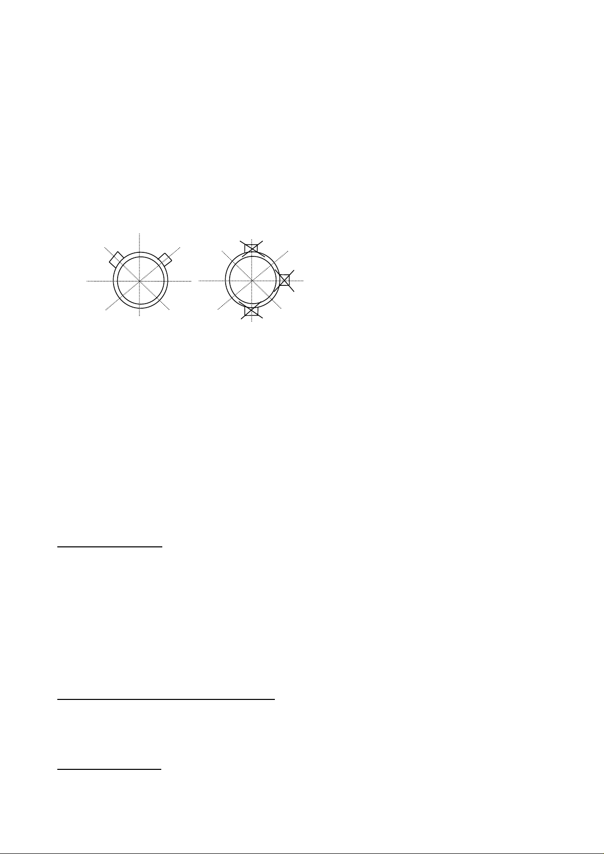
When ultrasound is transmitted from Transducer ‘A’ to Transducer ‘B’ (REFLEX MODE-Figure 6) or Transducer ‘A’
to ‘B’ (DIAGONAL MODE- Figure 7) the speed at which the sound travels through the liquid is accelerated slightly by
the velocity of the liquid. If sound is transmitted in the opposite direction from ‘B’ to ‘A’, it is decelerated against the
flow of the liquid. The differences in time taken to travel the same distance in opposite directions are directly
proportional to the flow velocity of the liquid.
Having measured the flow velocity and knowing the pipe cross-sectional area, the volumetric flow can be easily
calculated. The Microprocessor will determine the correct alignment of each transducer.
To measure flow, it is first necessary to obtain detailed information about each application, which is then programmed
into the processor via the Key Pad. This information must be accurate otherwise flow measurement errors will occur.
Further, having calculated the precise position at which the transducers must be clamped onto the pipe wall, it is equally
important to align and separate the transducers accurately with respect to one another, as failing to do so will again
cause errors in measurement.
Finally, to ensure accurate flow measurement it is imperative that the liquid is flowing uniformly within the pipe and
that the flow profile has not been distorted by any upstream or downstream obstructions.
To obtain the best results from the Portaflow 216 it is absolutely necessary that the following rules for positioning the
transducers and that the condition of the liquid and the pipe wall are suitable to allow transmission of the sound along
its predetermined path.
Reflex mode
‘A’
Diagonal mode
‘A
‘B’
‘B
17
Page 18

TRANSDUCER POSITIONING
As the transducers for the Portaflow 216 are clamped to the outside surface of the pipe, the meter has no way of
determining exactly what is happening to the liquid. The assumption therefore has to be made that the liquid is flowing
uniformly along the pipe either under fully turbulent conditions or under laminar flow conditions. Further it is assumed
that the flow velocity profile is uniform for 360° around the pipe axis.
Figure 8:- A uniform profile as compared to a distorted profile.
“A” “B”
The difference between (a) and (b) is that the Mean Velocity of the flow across the pipe is different and because the
Portaflow 216 expects a uniform flow as in (a), the distorted flow as in (b) will give measurement errors which cannot
be predicted or be compensated.
Flow profile distortions result from upstream disturbances such as bends, tees, valves, pumps and other similar
obstructio ns. To ensure a uniform profile the transducers must be mounted far enough away from any cause of
distortion such that it no longer has an effect.
Figure 9
:- Sensor Mounting
CORRECT
FLOW
INCORRECT
FLOW
> 20
10 20
5
FLOW
The minimum length of upstream straight pipe is 20 Diameters and 10 Diameters downstream that ensures accurate
results will be achieved.
Flow measurements can be made on shorter lengths of straight pipe down to 10 Diameters upstream and 5 Diameters
downstream, but when the transducers are sighted this close to any obstruction errors can be considerable.
It is not possible to predict the amount of error as this depends entirely upon the type of obstruction and the
configuration of the pipe work and flow profile.
The message therefore is clear: Do not expect to obtain accurate results if the transducers are positioned closer than
allowed to any obstruction that distorts the uniformity of the flow profile.
MOUNTING THE TRANSDUCERS
It will be impossible to achieve the accuracy of measurement specified for the Portaflow 216 if the transducers are not
clamped to the pipe correctly and if the data - I.D. O.D., Pipe Material - are not accurate.
Apart from the correct positioning and alignment of the transducers, of equal importance is the condition of the pipe
surface in the area under each of the transducers.
20
FLOW
< 20 D
18
Page 19
An uneven surface that prevents the transducers from sitting flat on the surface of the pipe can cause Signal Level and
Zero Offset problems. The following procedure is offered as a guide to good practice with respect to positioning and
mounting the transducers.
1) Select the site following the rules laid down on page 19 -
2) Inspect the surface of the pipe to ensure it is free from rust or is not uneven for any reason. Transducers can be
mounted directly on painted surfaces as long as the surface is smooth and that the underlying metal surface is free from
rust bubbles. On bitumen or rubber coated pipes the coating must be removed in the area under the transducer as it is
preferable that the transducers are mounted directly on to the base metal.
Transducers can be mounted on both Vertical and Horizontal Pipe Runs.
3)
Transducer Positioning.
Figure 10:- Sensor mounting position
TOP
4)
On Stainless Steel Pipes the amount of couplant applied should never exceed the amount indicated in the Example on
page 3, For large Plastic and Steel Pipes the amount of grease applied is less critical, however do not use more than is
absolutely necessary.
5) Strap the guide rail assembly to the pipe so that it is perfectly parallel to the pipe axis.
6) When screwing the transducers on to the p ipe surface use only enough force to ensure that the Transducer is flat
7) Clamping the transducers in exactly the correct position is extremely important. The Separation distance is
8) Always use the sensor grease provided.
LIQUID CONDITIONS
Transit time ultrasonic meters perform best on liquids that are totally free from entrained air and solids. With sufficient
air in the system the ultrasound beam can be attenuated totally and therefore prevent the instrument from working.
Often it is possible to tell whether there is air in the system or not. If a flow signal cannot be obtained a simple test to
determine whether the flow is aerated involves stopping the flow for a period of 10 - 15 minutes. During this time the
air bubbles will rise to the top of the pipe and the flow signal should return.
If the flow signal does return switch on the flow and if sufficient entrained air is locked in the system it will very
quickly disperse and kill the signal.
BOTTOM
Apply Interface grease to the face of the transducers. The amount of grease used is extremely important particularly
on pipes of less than 89mm bore.
against the pipe surface and then lock in position.
calculated by the Portaflow electronics and the transducers must be positioned and clamped exactly at the
distance specified.
CORREC
T
TOP
BOTTOM
INCORRECT
To correct the Portaflow 216 for operation in the laminar flow region, calculate the Reynolds number adjust the
correction factor
PROPAGATION VELOCITY or SOUND SPEED
To make a flow measurement using the Portaflow 216 on any liquid, it is necessary to know the propagation velocity in
metres/second. There is a short list of fluids that appear on the display when programming (See page 9), showing water
and various other liquids. However if the liquid you wish to measure is not on this list, please revert to the table at the
back of this manual or contact Micronics for advice.
REYNOLDS NUMBER
The Portaflow 216 has been calibrated to operate on Turbulent flows with Reynolds Number of approximately 100,000.
The calibration of the unit will not be valid if the Reynolds No.is below 4000.
as described on Page 15.
19
Page 20

If the Portaflow 216 is to be used on laminar flow applications it will be necessary to calculate the Reynolds No for
y
each application. To calculate the Reynolds No it is necessary to know the Kinematic viscosity in Centistokes; the flow
velocity and the pipe inside diameter. Please follow the table below
To calculate
R
=
e
Where
d
= inside pipe diameter in inches
1
d
= inside pipe diameter in millimetres
v
= velocity in feet/second
1
v
= velocity in metres/second
1
υ
= Kinematic viscosity in centistokes
dv
7730()
1
υ
R
use the following formula: -
e
11
or
dv
R
=
e
()
1
υ
1000
MAXIMUM FLOW
The maximum flow is dependent on the velocity and pipe size.
APPLICATION TEMPERATURE
On any application whose operating temperature is either above or below ambient temperature ensure that the
transducers reach and are maintained at the application temperature before undertaking a measurement.
When applying the transducers to low temperature applications do not allow the pipe surface to ice up between the
transducer and the pipe wall. The ice will force the block away from the pipe wall and consequently you will lose the
signal.
DIAGONAL MODE SETUP
Figure 11: Diagonal Mode parts supplied
Gull-wing
attachment
Sensor
stem
Spring
tensioning
Piezo
electric
cr
stal
As part of your New Portaflow 216 kit you will find
two stainless steel gull wings, two springs and two
lengths of chain.
Take the transducers from the reflex guiderail.
Attach the Gull-wing to each transducer using the
washer & wing nut provided.
Apply grease to the bottom of the transducer (as
shown on page3). Wrap the chain around the pipe
as shown. Expand the spring and carefully slide the
chain into the slot on the Gull Wing. Plug the red
connector into the socket on the upstream sensor.
The sensor with the red cable must be positioned up
stream. The stem of the sensor must point towards
the downstream sensor.
20
Page 21

Figure 12: Attaching the sensor to the pipe
f
p
Program the Electronics with the application data to
Gull wing and
spring
attachment
Peizo
electric
crystal
FLOW
obtain the calculated separation distance.
Measure the circumference of the pipe and mark a
position at the halfway point. (Outside Diameter of the
pipe times 3.142 divided by 2). Apply grease to the
second sensor and plug the blue connector into the top o
the sensor. Follow (figure 13) next diagram to set up the
sep distance.
Figure 13: Marking the Separation distance
Sensor stems to
A
FLOW
B
Seperation
distance in
Millimetres
Using a marker pen or a strip of ticket paper mark
around the pipe from the front edge of the first
sensor “A” till you reach the half way point of the
pipe. From “B” measure the separation distance
calculated by the electronics. Mount the second
transducer as per the first with the stem facing the
other transducer.
Press ENTER to view the flow. The signal strength
should be greater than 50%. Should you have
difficulty getting a signal remove the sensor from
the Gull wing re-apply the grease and try to find a
signal by moving it with your hand.
Figure 14: Positioning of the sensor cables
Red
connector
upstream
Position the Red sensor cable upstream and the Blue
cable Downstream. The Electronics will display a
ositive flow reading with cables in this orientation.
If the unit displays a negative reading the cables
have been connected into the wrong sensors.
FLOW
Blue connector
downstream
21
Page 22

PORTAFLOW™ 216 SPECIFICATION
ENCLOSURE:
Protection Class IP55
Material ABS
Weight < 1.5 Kg
Dimensions 235 x 125 x 42 mm
Display Graphics LCD display
Keypad 16 Key Tactile Membrane
Connections IP65 Lemo Connectors
Temperature Range 0°C to +50°C (operating)
-10° to +60°C (storage)
SUPPLY VOLTAGE:
Power supply/charger Input 100-240 VAC ±10% @50/60 Hz
Max. Power consumption 9 Watts
Output 9VDC Regulated
BATTERY PACK:
5 AA Nickel Metal Hydride 8hrs Operating Time
Rechargeable 15 hrs Charge Time
Low Battery Indication
OUTPUTS:
Display Volumetric Flow m3, litres, gallons (Imperial and US)
Flow Velocity metres/sec, feet/sec
Flow Rate 0.3…12 m/sec to 4 significant figures
Total Flow 12 Digits (Forward and Reverse)
Continuous Battery Level Indication
Continuous Signal Level Indication
ERROR messages
Analogue
Resolution 0.1% of full scale
TRANSDUCERS:
‘B’ 50 mm…400mm pipe 0.3 m/sec… 6 m/sec (12 m/sec)
Standard Temperature range -20°C to +125°C
REPEATABILITY:
±0.5% with unchanged transducer position
ACCURACY:
± 1-3% of reading within velocity range or ± 0.3 m/sec and under ideal flowing conditions and on a 4” plastic
pipe. Micronics cannot guarantee the performance of the Portaflow 216 unless ideal conditions are achieved
Specification assumes turbulent flow profile with Reynolds numbers above 4000.
PIPE MATERIALS
Any sonic conducting medium such as Carbon Steel, Stainless Steel, Copper, UPVC, PVDF, Concrete,
Galvanised Steel, Mild Steel, Glass, Brass. Including Lined Pipes – Epoxy, Rubber, Steel, Plastic.
4 - 20mA into 750 Ω
Frequency Velocity Range Reflex (Diagonal Mode)
Micronics reserve the right to alter any specification without notification.
User Definable Scaling
22
Page 23
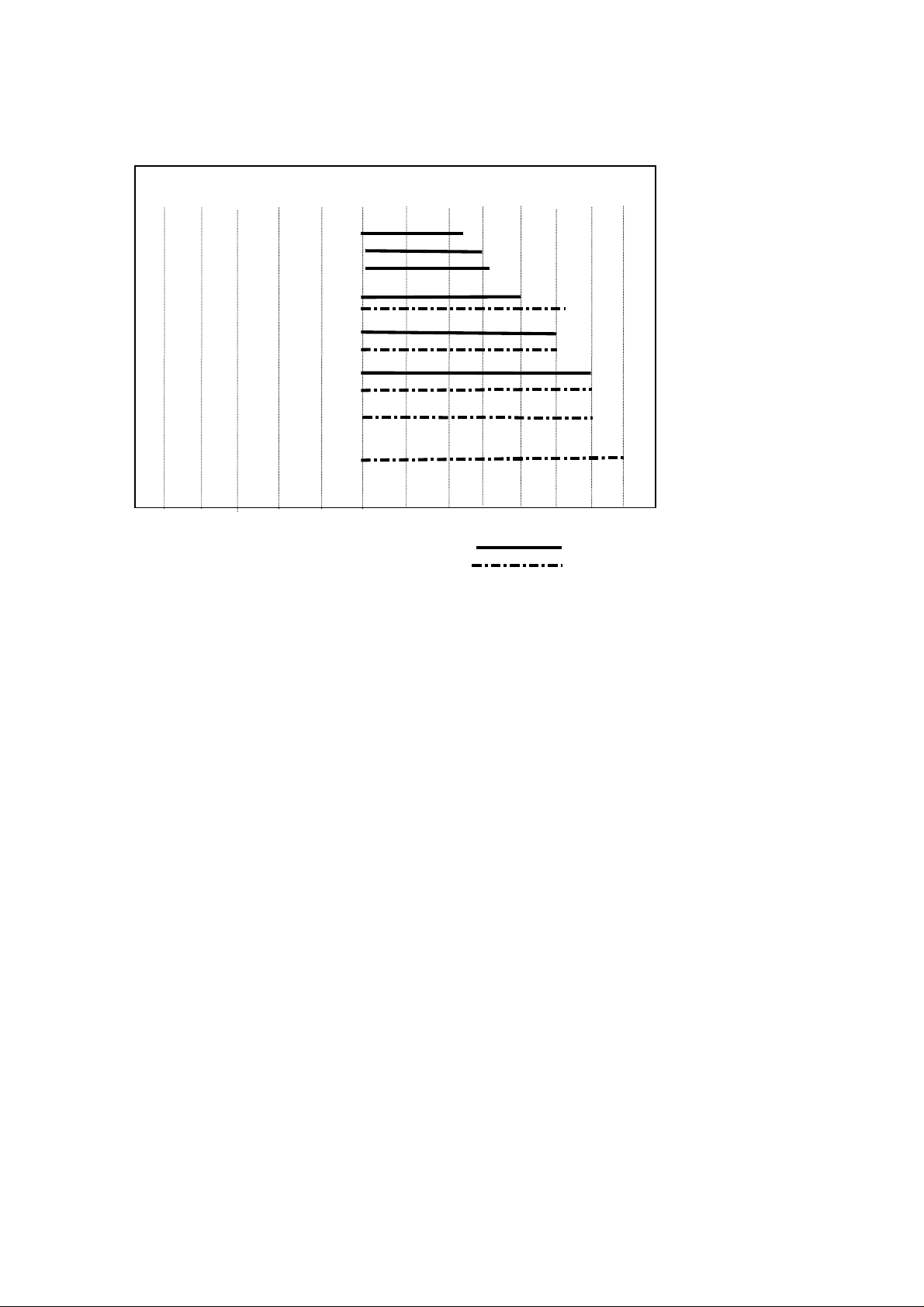
Figure 15
PORTAFLOW 216 Flow Range
:-
200
150
100
75
50
25
13
0.07 0.10 0.13 0.22 0.29 0.32 0.42 5.9 8.2 11.40 14.76 23.94 30.90 fps
0
0.02 0.03 0.04 0.07 0.09 0.10 0.13 1.8 2.5 3.5 4.5 7.3 9.4 mps
PORTAFLOW 216 FLOW RANGE - DIAGONAL MODE
PORTAFLOW 216 FLOW RANGE – REFLEX MODE
WARRANTY
The material and workmanship of the PORTAFLOW 216 is guaranteed by MICRONICS LTD for one year from the
date of purchase provided the equipment has been used for the purpose for which it has been designed, and operated in
accordance with the operating manual supplied.
Misuse by the purchaser, or any other person, will immediately revoke any warranty given or implied.
Repair or replacement will be at MICRONICS discretion and will be made without charge at MICRONICS plant during
the warranty period. MICRONICS LTD reserve the right, without prior notice, to discontinue manufacture, redesign or
modify any of its products. Your statutory rights are not affected by this warranty.
If any problems develop, customers are requested to take the following steps:
Notify MICRONICS LTD or the Distributor/Agent from whom the flowmeter was purchased giving details of the
problem. Be sure to include the Model & Serial Number of the instrument. When returning the product to the factory,
carefully package and ship freight prepaid. Be sure to include a complete description of the application and problem
and identify any hazardous material used with the product. The Warranty of the PORTAFLOW is strictly in
accordance with that stated above, and cannot in any way be extended.
CE MARKING
The PORTAFLOW 216 has been tested and found to conform to EN50081 - 1 Emission Standards and EN50082 - 1
Immunity Standards. The tests were conducted by AQL - EMC Ltd, of 16 Cobham Road, Ferndown Industrial Estate,
Wimborne, U.K. BH21 7PG. The unit was tested with all cables as supplied of a maximum length of 3m. While the
operation of the unit may not be affected by the use of longer cables, MICRONICS can make no statement about
conformance to the above standards when these cables are in use.
The PORTAFLOW 216 is supplied with an external battery charging unit. This unit is manufactured by Frieman &
Wolf, Geratebau GmbH. P.O. Box 1164 D-48342 Ostbevan, Germany who have CE marked the equipment.
MICRONICS have purchased this equi pment on the understanding that the manufacturers have tested the unit to the
relevant standards prior to CE marking the product. MICRONICS have not tested the charger unit and cannot accept
responsibility for any non conformance from the relevant standards.
23
Page 24

LIQUID SOUND SPEEDS
Liquid Sound Speeds
Note: All the following sound speeds a re calculated at 25°C.
The speed of sound in liquids at temperatures other than 25°C are calculated as follows.
Example:
Substance Form Index Specific
Gravity
Sound
Speed
∆∆∆∆
v/ºC -
m/s/ºC
Glycol C2H6O2 1.113 1658 2.1
Water, distilled (49,50) H2O 0.996 1498 -2.4
For every 1°C higher than 25°C take off the value in the Δv/°C- m/s/°C column.
Glycol at 50°C = 1658 - (2.1 x 25) = 1605.5
For every 1°C less than 25°C add on the value in the Δv/°C- m/s/°C column.
Glycol at 5°C = 1658 + (2.1 x 20) = 1700
If the value has a minus sign in front of it then do the opposite of above.
Distilled Water at 50°C = 1498 - (-2.4 x 25) =1558
Distilled Water at 10°C = 1498 + (-2.4 x 15) = 1462
24
Page 25

Substance Form Index Specific Gravity Sound Speed
∆∆∆∆
v/ºC -
m/s/ºC
Acetic anhydride (22)
Acetic acid, anhydride (22)
Acetic acid, nitrile
Acetic acid, ethyl ester (33)
Acetic acid, methyl ester
Acetone
(CH3CO)2O
(CH3CO)2O
C2H3N
C4H8O
C3H6O
C3H6O
2
2
1.082 (20ºC)
1.082 (20ºC)
0.783
0.901
0.934
0.791
1180
1180
1290
1085
1211
1174
2.5
2.5
4.1
4.4
4.5
Acetonitrile C2H3N 0.783 1290 4.1
Acetonylacetone C6H10O2 0.729 1399 3.6
Acetylene dichloride C2H2Cl2 1.26 1015 3.8
Acetylene tetrabromide (47) C2H2Br4 2.966 1027
Acetylene tetrachloride (47) C2H2Cl4 1.595 1147
Alcohol C2H6O 0.789 1207 4.0
Alkazene-13 C15H24 0.86 1317 3.9
Alkazene-25 C10H12Cl2 1.20 1307 3.4
2-Amino-ethanol C2H7NO 1.018 1724 3.4
2-Aminotolidine (46) C7H9N 0.999 (20ºC) 1618
4-Aminotolidine (46) C7H9N 0.966 (45ºC) 1480
Ammonia (35) NH3 0.771 1729 6.68
Amorphous Polyolefin 0.98 962.6
t-Amyl alcohol C5H12O 0.81 1204
Aminobenzene (41) C6H5NO2 1.022 1639 4.0
Aniline (41) C6H5NO2 1.022 1639 4.0
Argon (45) Ar 1.400 (-188ºC) 853
Azine C6H5N 0.982 1415 4.1
Benzene (29,40,41) C6H6 0.879 1306 4.65
Benzol (29,40,41) C6H6 0.879 1306 4.65
Bromine (21) Br2 2.928 889 3.0
Bromo-benzene (46) C6H5Br 1.522 1170
1-Bromo-butane (46) C4H9Br 1.276 (20ºC) 1019
Bromo-ethane (46) C2H5Br 1.460 (20ºC) 900
Bromoform (46,47) CHBr3 2.89 (20ºC) 918 3.1
n-Butane (2) C4H10 0.601 (0ºC) 1085 5.8
2-Butanol C4H10O 0.81 1240 3.3
sec-Butylalcohol C4H10O 0.81 1240 3.3
n-Butyl bromide (46) C4H9Br 1.276 (20ºC) 1019
n-Butyl chloride (22,46) C4H9Cl 0.887 1140 4.57
tert Butyl chloride C4H9Cl 0.84 984 4.2
Butyl oleate C22H42O2 1404 3.0
2,3 Butylene glycol C4H10O2 1.019 1484 1.51
Cadmium (7) Cd 2237.7
Carbinol (40,41) CH4O 0.791 (20ºC) 1076 2.92
Carbitol C6H14O3 0.988 1458
Carbon dioxide (26) CO2 1.101 (-37ºC) 839 7.71
Carbon disulphide CS2 1.261 (22ºC) 1149
Carbon tetrachloride(33,35,47) CCl4 1.595 (20ºC) 926 2.48
Carbon tetrafluoride (14) CF4 1.75 (-150ºC) 875.2 6.61
Cetane (23) C16H34 0.773 (20ºC) 1338 3.71
Chloro-benezene C6H5Cl 1.106 1273 3.6
1-Chloro-butane (22,46) C4H9Cl 0.887 1140 4.57
Chloro-diFluoromethane (3) (Freon 22) CHClF2 1.491 (-69ºC) 893.9 4.79
Chloroform (47) CHCl3 1.489 979 3.4
1-Chloro-propane (47) C3H7Cl 0.892 1058
Chlorotrifluoromethane (5) CClF3 724 5.26
Cinnamaldehyde C9H8O 1.112 1554 3.2
Cinnamic aldehyde C9H8O 1.112 1554 3.2
Colamine C2H7NO 1.018 1724 3.4
o-Cresol (46) C7H8O 1.047 (20ºC) 1541
m-Cresol (46) C7H8O 1.034 (20ºC) 1500
Cyanomethane C2H3N 0.783 1290 4.1
Cyclohexane (15) C6H12 0.779 (20ºC) 1248 5.41
25
Page 26

Cyclohexanol C6H12O 0.962 1454 3.6
Cyclohexanone C6H10O 0.948 1423 4.0
Decane (46) C10H22 0.730 1252
1-Decene (27) C10H20 0.746 1235 4.0
n-Decylene (27 ) C10 H20 0.746 1235 4.0
Diacetyl C4H6O2 0.99 1236 4.6
Diamylamine C10H23N 1256 3.9
1,2 Dibromo-ethane (47) C2H4Br2 2.18 995
trans-1,2-Dibromoethene(47) C2H2Br2 2.231 935
Dibutyl phthalate C8H22O4 1408
Dichloro-t-butyl alcohol C4H8Cl2O 1304 3.8
2,3 Dichlorodioxane C2H6Cl2O2 1391 3.7
Dichlorodifluoromethane (3) (Freon 12) CCl2F2 1.516(-40ºC) 774.1 4.24
1,2 Dichloro ethane (47) C2H4Cl2 1.253 1193
cis 1,2-Dichloro-Ethene(3,47) C2H2Cl2 1.284 1061
trans 1,2-Dichloro-ethene(3,47) C2H2Cl2 1.257 1010
Dichloro-fluoromethane (3) (Freon 21) CHCl2F 1.426 (0ºC) 891 3.97
1-2-Dichlorohexafluoro cyclobutane (47) C4Cl2F6 1.654 669
1-3-Dichloro-isobutane C4H8Cl2 1.14 1220 3.4
Dichloro methane (3) CH2Cl2 1.327 1070 3.94
1,1-Dichloro-1,2,2,2 tetra fluoroethane CClF2-CClF2 1.455 665.3 3.73
Diethyl ether C4H10O 0.713 985 4.87
Diethylene glycol, monoethyl ether C6H14O3 0.988 1458
Diethylenimide oxide C4H9NO 1.00 1442 3.8
1,2-bis(DiFluoramino) butane (43) C4H8(NF2)2 1.216 1000
1,2bis(DiFluoramino)- 2-methylpropane
(43)
1,2bis(DiFluoramino) propane (43) C3H6(NF2)2 1.265 960
2,2bis(DiFluoramino) propane (43) C3H6(NF2)2 1.254 890
2,2-Dihydroxydiethyl ether C4H10O3 1.116 1586 2.4
Dihydroxyethane C2H6O2 1.113 1658 2.1
1,3-Dimethyl-benzene (46) C8H10 0.868 (15ºC) 1343
1,2-Dimethyl-benzene(29,46) C8H10 0.897 (20ºC) 1331.5
1,4-Dimethyl-benzene (46) C8H10 1334
2,2-Dimethyl-butane (29,33) C6H14 0.649 (20ºC) 1079
Dimethyl ketone C3H6O 0.791 1174 4.5
Dimethyl pentane (47) C7H16 0.674 1063
Dimethyl phthalate C8H10O4 1.2 1463
Diiodo-methane CH2I2 3.235 980
Dioxane C4H8O2 1.033 1376
Dodecane (23) C12H26 0.749 1279 3.85
1,2-Ethanediol C2H6O2 1.113 1658 2.1
Ethanenitrile C2H3N 0.783 1290
Ethanoic anhydride (22) (CH3CO)2O 1.082 1180
Ethanol C2H6O 0.789 1207 4.0
Ethanol amide C2H7NO 1.018 1724 3.4
Ethoxyethane C4H10O 0.713 985 4.87
Ethyl acetate (33) C4H8O2 0.901 1085 4.4
Ethyl alcohol C2H6O 0.789 1207 4.0
Ethyl benzene (46) C8H10 0.867(20ºC) 1338
Ethyl bromide (46) C2H5Br 1.461 (20ºC) 900
Ethyliodide (46) C2H5I 1.950 (20ºC) 876
Ether C4H10O 0.713 985 4.87
Ethyl ether C4H10O 0.713 985 4.87
Ethylene bromide (47) C2H4Br2 2.18 995
Ethylene chloride (47) C2H4Cl2 1.253 1193
Ethylene glycol C2H6O2 1.113 1658 2.1
50% Glycol/ 50% H2O 1578
d-Fenochone C10H16O 0.947 1320
d-2-Fenechanone C10H16O 0.947 1320
Fluorine F 0.545 (-143ºC) 403 11.31
C4H9(NF2)2 1.213 900
4.I
26
Page 27

Fluoro-benzene (46) C6H5F 1.024 (20ºC) 1189
Formaldehyde, methyl ester C2H4O2 0.974 1127 4.02
Formamide CH3NO 1.134 (20ºC) 1622 2.2
Formic acid, amide CH3NO 1.134 (20ºC) 1622
Freon R12 774.2
Furfural C5H4O2 1.157 1444
Furfuryl alcohol C5H6O2 1.135 1450 3.4
Fural C5H4O2 1.157 1444 3.7
2-Furaldehyde C5H4O2 1.157 1444 3.7
2-Furancarboxaldehyde C5H4O2 1.157 1444 3.7
2-Furyl-Methanol C5H6O2 1.135 1450 3.4
Gallium Ga 6.095 2870 (30ºC)
Glycerin C3H8O3 1.26 1904 2.2
Glycerol C3H8O3 1.26 1904 2.2
Glycol C2H6O2 1.113 1658 2.1
Helium (45) He4 0.125(-268.8ºC) 183
Heptane (22,23) C7H16 0.684 (20ºC) 1131 4.25
n-Heptane (29,33) C7H16 0.684 (20ºC) 1180 4.0
Hexachloro-Cyclopentadiene(47) C5Cl6 1.7180 1150
Hexadecane (23) C16H34 0.773 (20ºC) 1338 3.71
Hexalin C6H12O 0.962 1454 3.6
Hexane (16,22,23) C6H14 0.659 1112 2.71
n-Hexane (29,33) C6H14 0.649 (20ºC) 1079 4.53
2,5-Hexanedione C6H10O2 0.729 1399 3.6
n-Hexanol C6H14O 0.819 1300 3.8
Hexahydrobenzene (15) C6H12 0.779 1248 5.41
Hexahydrophenol C6H12O 0.962 1454 3.6
Hexamethylene (15) C6H12 0.779 1248 5.41
Hydrogen (45) H2 0.071 (-256ºC) 1187
2-Hydroxy-toluene (46) C7H8O 1.047 (20ºC) 1541
3-Hydroxy-tolune (46) C7H8O 1.034 (20ºC) 1500
Iodo-benzene (46) C6H5I 1.823 1114
Iodo-ethane (46) C2H5I 1.950 (20ºC) 876
Iodo-methane CH3I 2.28 (20ºC) 978
Isobutyl acetate (22) C6H12O 1180 4.85
Isobutanol C4H10O 0.81 (20ºC) 1212
Iso-Butane 1219.8
Isopentane (36) C5H12 0.62 (20ºC) 980 4.8
Isopropanol (46) C3H8O 0.785 (20ºC) 1170
Isopropyl alcohol (46) C3H8O 0.785 (20ºC) 1170
Kerosene 0.81 1324 3.6
Ketohexamethylene C6H10O 0.948 1423 4.0
Lithium fluoride (42) LiF 2485 1.29
Mercury (45) Hg 13.594 1449
Mesityloxide C6H16O 0.85 1310
Methane (25,28,38,39) CH4 0.162 405(-89.15ºC) 17.5
Methanol (40,41) CH4O 0.791 (20ºC) 1076 2.92
Methyl acetate C3H6O2 0.934 1211
o-Methylaniline (46) C7H9N 0.999 (20ºC) 1618
4-Methylaniline (46) C7H9N 0.966 (45ºC) 1480
Methyl alcohol (40,44) CH4O 0.791 (20ºC) 1076 2.92
Methyl benzene (16,52) C7H8 0.867 1328 4.27
2-Methyl-butane (36) C5H12 0.62 (20ºC) 980
Methyl carbinol C2H6O 0.789 1207 4.0
Methyl-chloroform (47) C2H3Cl3 1.33 985
Methyl-cyanide C2H3N 0.783 1290
3-Methyl cyclohexanol C7H14O 0.92 1400
Methylene chloride (3) CH2Cl2 1.327 1070 3.94
Methylene iodide CH2I2 3.235 980
Methyl formate (22) C2H4O2 0.974 (20ºC) 1127 4.02
Methyl iodide CH3I 2.28 (20ºC) 978
1.090 1510 3.7
-Methyl naphthalene
α
C
11H10
27
Page 28

2-Methylphenol (46) C7H8O 1.047 (20ºC) 1541
3-Methylphenol (46) C7H8O 1.034 (20ºC) 1500
Milk, homogenized 1548
Morpholine C4H9NO 1.00 1442 3.8
Naphtha 0.76 1225
Natural Gas (37) 0.316 (-103ºC) 753
Neon (45) Ne 1.207 (-246ºC) 595
Nitrobenzene (46) C6H5NO2 1.204 (20ºC) 1415
Nitrogen (45) N2 0.808 (-199ºC) 962
Nitromethane (43) CH3NO2 1.135 1300 4.0
Nonane (23 ) C9H2O 0.718 (20ºC) 1207 4.04
1-Nonene (27) C9H18 0.736 (20ºC) 1207 4.0
Octane (23) C8H18 0.703 1172 4.14
n-Octane (29) C8H18 0.704 (20ºC) 1212.5 3.50
1-Octene (27) C8H16 0.723 (20ºC) 1175.5 4.10
Oil of Camphor Sassafrassy 1390 3.8
Oil, Car (SAE 20a.30) 1.74 870
Oil, Castor C11H10O10 0.969 1477 3.6
Oil, Diesel 0.80 1250
Oil, Fuel AA gravity 0.99 1485 3.7
Oil (Lubricating X200) 1530 5019.9
Oil (Olive) 0.912 1431 2.75
Oil (Peanut) 0.936 1458
Oil (Sperm) 0.88 1440
Oil, 6 1509
2,2-Oxydiethanol C4H10O3 1.116 1586 2.4
Oxygen (45) O2 1.155 (-186ºC) 952
Pentachloro-ethane (47) C2HCl5 1.687 1082
Pentalin (47) C2HCl5 1.687 1082
Pentane (36) C5H12 0.626 (20ºC) 1020
n-Pentane (47) C5H12 0.557 1006
Perchlorocyclopentadiene(47) C5Cl6 1.718 1150
Perchloro-ethylene (47) C2Cl4 1.632 1036
Perfluoro-1-Hepten (47) C7F14 1.67 583
Perfluoro-n-Hexane (47) C6F14 1.672 508
Phene (29,40,41) C6H6 0.879 1306 4.65
O 1.112 1554 3.2
-Phenyl acrolein
β
C
9H8
Phenylamine (41) C6H5NO2 1.022 1639 4.0
Phenyl bromide (46) C6H5Br 1.522 1170
Phenyl chloride C6H5Cl 1.106 1273 3.6
Phenyl iodide (46) C6H5I 1.823 1114
Phenyl methane (16,52) C7H8 0.867 (20ºC) 1328 4.27
3-Phenyl propenal C9H8O 1.112 1554 3.2
Phthalardione C8H4O3 1125
Phthalic acid, anhydride C8H4O3 1125
Phthalic anhydride C8H4O3 1125
Pimelic ketone C6H10O 0.948 1423 4.0
Plexiglas, Lucite, Acrylic 2651
Polyterpene Resin 0.77 1099.8
Potassium bromide (42) Kbr 1169 0.71
Potassium fluoride (42) KF 1792 1.03
Potassium iodide (42) KI 985 0.64
Potassium nitrate (48) KNO3 1.859 (352ºC) 1740.1 1.1
Propane (2,13)(-45 to -130ºC) C3H8 0.585 (-45ºC) 1003 5.7
1,2,3-Propanetriol C3H8O3 1.26 1904 2.2
1-Propanol (46) C3H8O 0.78 (20ºC) 1222
2-Propanol (46) C3H8O 0.785 (20ºC) 1170
2-Propanone C3H6O 0.791 1174 4.5
Propene (17,18,35) C3H6 0.563 (-13ºC) 963 6.32
n-Propyl acetate (22) C5H10O2 1280 (2ºC) 4.63
n-Propyl alcohol C3H8O 0.78 (20ºC) 1222
Propylchloride (47) C3H7Cl 0.892 1058
28
Page 29

Propylene (17,18,35) C3H6 0.563 (-13ºC) 963 6.32
Pyridine C6H5N 0.982 1415 4.1
Refrigerant 11 (3,4) CCl3F 1.49 828.3 3.56
Refrigerant 12 (3) CCl2F2 1.516 (-40ºC) 774.1 4.24
Refrigerant 14 (14) CF4 1.75 (-150ºC) 875.24 6.61
Refrigerant 21 (3 ) CHCl2F 1.426 (0ºC) 891 3.97
Refrigerant 22 (3) CHClF2 1.491 (-69ºC) 893.9 4.79
Refrigerant 113 (3) CCl2F-CClF2 1.563 783.7 3.44
Refrigerant 114 (3) CClF2-CClF2 1.455 665.3 3.73
Refrigerant 115 (3) C2ClF5 656.4 4.42
Refrigerant C318 (3) C4F8 1.62 (-20ºC) 574 3.88
Selenium (8) Se 1072 0.68
Silicone (30 cp) 0.993 990
Sodium fluoride (42) NaF 0.877 2082 1.32
Sodium nitrate (48) NaNO3 1.884 (336ºC) 1763.3 0.74
Sodium nitrite (48) NaNO2 1.805 (292ºC) 1876.8
Solvesso 3 0.877 1370 3.7
Spirit of wine C2H6O 0.789 1207 4.0
Sulphur (7,8,10) S 1177 -1.13
Sulphuric acid (1) H2SO4 1.841 1257.6 1.43
Tellurium (7) Te 991 0.73
1,1,2,2-Tetrabromo-ethane(47) C2H2Br4 2.966 1027
1,1,2,2-Tetrachloro-ethane(67) C2H2Cl4 1.595 1147
Tetrachloroethane (46) C2H2Cl4 1.553 (20ºC) 1170
Tetrachloro-ethene (47) C2Cl4 1.632 1036
Tetrachloro-methane (33,47) CCl4 1.595 (20ºC) 926
Tetradecane (46) C14H3O 0.763 (20ºC) 1331
Tetraethyle ne glycol C8H18O5 1.123 1586/5203.4 3.0
Tetrafluoro-methane (14) (Freon 14) CF4 1.75 (-150ºC) 875.24 6.61
Tetrahydro-1,4-isoxazine C4H9NO 1442 3.8
Toluene (16,52) C7H8 0.867 (20ºC) 1328 4.27
o-Toluidine (46) C7H9N 0.999 (20ºC) 1618
p-Toluidine (46) C7H9N 0.966 (45ºC) 1480
Toluol C7H8 0.866 1308 4.2
Tribromo-methane (46,47) CHBr3 2.89 (20ºC) 918
1,1,1-Trichloro-ethane (47) C2H3Cl3 1.33 985
Trichloro-ethene (47) C2HCl3 1.464 1028
Trichloro-fluoromethane (3) (Freon 11) CCl3F 1.49 828.3 3.56
Trichloro-methane (47) CHCl3 1.489 979 3.4
1,1,2-Trichloro-1,2,2-Trifluoro-Ethane CCl2F-CClF2 1.563 783.7
Triethyl-amine (33) C6H15N 0.726 1123 4.47
Triethylene glycol C6H14O4 1.123 1608 3.8
1,1,1-Trifluoro-2-Chloro-2-Bromo-Ethane C2HClBrF3 1.869 693
1,2,2-Trifluorotrichloro- ethane (Freon 113) CCl2F-CClF2 1.563 783.7 3.44
d-1,3,3-Trimethylnor- camphor C10H16O 0.947 1320
Trinitrotoluene (43) C7H5(NO2)3 1.64 1610
Turpentine 0.88 1255
Unisis 800 0.87 1346
Water, distilled (49,50) H2O 0.996 1498 -2.4
Water, heavy D²O 1400
Water, sea 1.025 1531 -2.4
Wood Alcohol (40,41) CH4O 0.791 (20ºC) 1076 2.92
Xenon (45) Xe 630
m-Xylene (46) C8H10 0.868 (15ºC) 1343
o-Xylene (29,46) C8H10 0.897 (20ºC) 1331.5 4.1
p-Xylene (46) C8H10 1334
Xylene hexafluori de C8H4F6 1.37 879
Zinc (7) Zn 3298
29
Page 30

PORTAFLOW 216 Battery Charge circuit Operation.
Charging Controller IC:
A Maxim IC MAX712 or MAX713 controls the Ni-Cd and Ni-Mh battery charger. It has two
modes, fast charge and trickle charge; an output indicates the fast-charge status. In both modes it supplies,
via a PNP power transistor, a constant current to the battery, by keeping a constant voltage across a current
sensing resistor. In fast charge mode it is 250mV, in trickle charge mode 31mV, so the trickle charge current
is 1/8 of the fast charge current.
By wiring up input pins on the IC, the number of cells is set to 5, the voltage sampling interval to
168 sec, and the fast-charge time limit to 264 minutes (the maximum). The battery temperature limits are not
used.
The IC starts the fast-charge timer when a battery is connected or when power is applied. It
terminates the fast charge and returns to trickle charge, either after the 264 min (~4.5 hrs) time limit, or when
it senses that the battery voltage remains constant or begins to decrease, meaning that the battery is fully
charged.
Charging Voltage:
The voltage available to charge the 6V battery is restricted by the 9V charger input and the two
diodes in the input. The S2D silicon diodes had a fwd drop of 0.75V, limiting the available charge voltage to
7.5V, which caused the MAX712 to sense that the battery voltage had stopped rising, and therefore
prematurely end the fast charge. With several days of trickle charging the battery could however still reach
its full capacity.
In Dec.2000 the S2D diodes were replaced by SS14 Schottky diodes with a fwd drop of 0.35V, thus
raising the available charge voltage to 8.3V. At the same time the current was increased.
Instrument differences:
The current sensing resistor consists of either 2 or 4 parallel 1.2Ω resistors, giving about 0.4A or
0.8A fast-charge current.
PF-300 and UFM610P:
Battery Capacity 3.5Ah, or 4.0Ah after Oct.2000
Current 0.4A before, 0.8A after Dec.2000
PF-SE and 216:
Battery Capacity 1.2Ah
Current 0.4A
Software:
The fast-charge status output is not used by the present software (ver.3.06); in a future software
update a message will be added, indicating charging status.
30
Page 31

Quicker full charge:
The fastest way to fully charge the battery is to charge for 4.5 hrs, then switch the power supply off
and on again, thus re-starting the fast charge for another 4.5 hr period, followed by trickle charge.
Warning:
If the battery is getting warm, that would indicate that it is full, and the power supply should not be
connected again - overcharging reduces the life of the battery.
Note:
After a recently fully charged battery is connected to the charger, it seems that it takes the MAX712 about 30
min to sense that the battery voltage stops changing, and go to trickle charge.
Examples:
Older PF-300:-
A 15 hour charge consists of 4.5 hrs of fast charge (400mA), followed by 10.5 hrs of
trickle charge (50mA): 4.5*0.4+10.5*0.05=2.325Ah=3.5Ah*0.66, which fills the battery to 66% of capacity
(3.5Ah).
To fill the remaining 34% at 50mA takes 3.5*0.34/0.05=23.8hrs, +15hrs = 39hrs to 100%.
Assuming 20% losses:
(3.5Ah*20%)/50mA=0.7Ah/0.05A=14hrs of
trickle charge to cover losses, +39hrs=53hrs total.
In fact it needs ~9hrs * 0.4A = 3.6Ah to fill the battery from empty to 103% full capacity.
Assuming 20% losses:
(3.5Ah*20%-0.1)/50mA=0.6Ah/0.05A=12hrs of trickle charge to cover losses, +9hrs=21hrs total.
A third session of fast charge would fill the last 17% in 3.5Ah*17%/0.4A=1.5hrs, = 10.5hrs total.
Newer PF-300:-
4.5hrs fast: 0.8A*4.5h=3.6Ah = 90% of 4.0Ah
Slow: 10%= 0.4Ah/0.1A = 4h, total 8.5h to 100%
with 20% losses: 0.8Ah/0.1A = 8h
Total time fast and slow: 16.5hrs to 120%.
Fast only: 4.0Ah/0.8A=5hrs, +20%=6hrs,
that needs 2 sessions: 4.5hrs + 1.5hrs to 120%.
PF-SE & 216:-
1.2Ah/0.4A=3hrs to 100% capacity; with 20% losses 3h+20%=3.6hrs total.
This is well within the first 4.5hrs.
Micronics Ltd
Knaves Beech Business Centre,
Davies Way, Loudwater, High Wycombe,
Bucks. HP10 9QR
U.K.
Telephone: +44 (0) 1628 810456
Fax: +44 (0) 1628 531540
www.micronicsltd.co.uk
e-mail – sales@micronicsltd.co.uk
31
Page 32

Micronics Ltd
Knaves Beech Business Centre,
Davies Way, Loudwater, High Wycombe,
Bucks. HP10 9QR
U.K.
Telephone: +44 (0) 1628 810456
Fax: +44 (0) 1628 531540
www.micronicsltd.co.uk
e-mail – sales@micronicsltd.co.uk
32
 Loading...