

Page 1

PORTAFLOW 204 Plus!
Flowmeter
Operating Manual
Micronics Ltd, Knaves Beech Business Centre, Davies Way,
Loudwater, High Wycombe, Bucks. HP10 9QR
TEL: +44 (0) 1628 810456 FAX: +44 (0) 1628 531540
e-mail
sales@micronicsltd. co.uk
Web site www.micronicsltd.co.uk
Page 2

CONTENTS
Page No
System Component Pack
1
Introduction 1
Transducer Mounting
2
Programming – Main Menu 4
Main Menu – Quick Start 4
Main Menu – View/Edit site data 6
Main Menu – Select sensor set 7
Main Menu – Set up Instrument 7
Keypad Options – Pulse, 4-20mA, RS232, Logger, Options 8
Status/Error/Warning messages 10
Application and Performance 12
Flow Range 12
Specification 13
Warranty 14
CE Marking 14
Liquid Sound Speeds 15
Battery Charge Circuit Operation 19
Product Care and Maintenance 21
1. Portaflow Electronics 855-0016A
2. Sensor Assembly complete 855-0015A
3. Interconnecting Cables 740-0007
4. Ultrasonic Couplant 292-0020
5. Carrying Case 855-0013
6. Operating Manual 855-1000
7. Rechargeable Battery Pack 740-0005
System Component Pack
204 Plus!!
PORTAFLOW 204 Plus!!
INTRODUCTION
The PORTAFLOW 204 Plus!!! non-invasive Ultrasonic portable flow meter has been designed
to help Service, Maintenance and Commissioning Engineers make quick, accurate flow
readings of any liquids in pipes from 13mm internal diameter to 115mm outside Diameter.
These compact, rugged instruments will measure flow rate in litres/second, litres/minute,
gallons/minute, US gallons/minute, m
as litres, gallons, US gallons and m
Simple to set up, the PORTAFLOW is able to accurately measure the flow of clear or cloudy
liquids from 0.3 metres per second up to 8 metres per second, in any pipe material and over a
temperature range of -20°C to +125°C.
Programming is menu driven with the user supplying OD, wall thickness, pipe material and
pipe temperature information when measuring water. Liquid sound speed data is required
when measuring other fluids. It is possible to program the instrument and mount the
transducers in under 2 minutes, with stable flow data becoming available immediately. The
unit is powered by a rechargeable battery pack included in the instrument, which gives an
operating life of 8-10 hours from full charge. For continuous operation the meter can be
operated from the mains, via the battery charger.
3
/hour, metres/second or feet/sec. The total is displayed
3
.
1
Page 3

TRANSDUCER MOUNTING
1. OPERATION COMMENT
1.1 Remove oxidization, bitumen
or rubber from pipe surface
where the transducer
assembly is to be mounted.
Mounting transducer assembly.
1.2 Turn the two knurled lock nuts
on the rail assembly (figure
3a), CLOCKWISE to withdraw
the transducers into the guide
rail and then apply ultrasonic
couplant as shown in figure 2,
page 3.
1.3 Position transducer assembly
Very thick asbestos, concrete, old
porous cast iron tubes and steel
pipes with scaled or badly corroded
internal surfaces can weaken the
signal and prevent the unit from
operating correctly.
Straight pipe lengths either side of
the flow sensors should be 20
diameters UPSTREAM and 10
diameters DOWNSTREAM.
See figures 1a and 1b, page 3.
The guide rail assembly must be in
onto prepared section of pipe
as recommended at 1.1. The
fixed transducer (Blue) should
be DOWNSTREAM from the
floating transducer (Red).
Strap to pipe securely using
the ball chain attached to the
rail.
1.4 Turn the knurled lock nut for
the fixed transducer ANTICLOCKWISE to contact pipe
surface.
1.5 Connect transducer assembly
to the handset with the cables
alignment with the pipe axis and
positioned as shown in figure 3b
when attached to a horizontal pipe.
If the sensor cables are connected
in reverse the instrument will
display a negative flow rate, but this
will not affect the accuracy of the
reading.
Do not over tighten. Do not lock
the floating transducer until the
‘separation distance’ has been
determined after programming the
unit.
The Portaflow is now ready to
program.
provided.
2
Page 4
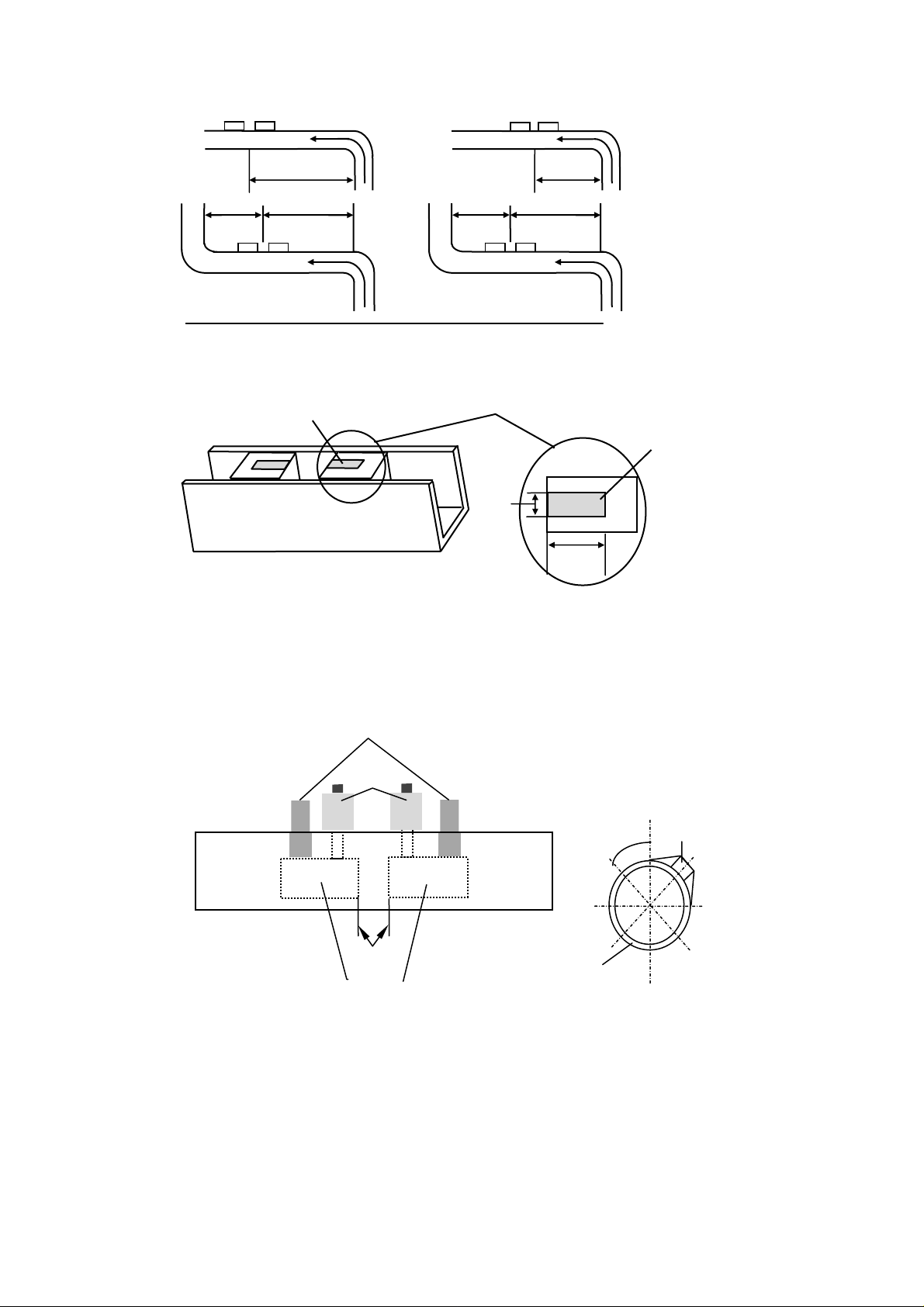
Fig 1a. Fig 1b.
0d
CORRECT INCORRECT
DN
UP
DN
UP
>10d
DN
FLOW
>20d
>20d
UP
FLOW
<10d
FLOW
<20d
<2
UP
DN
FLOW
Fig 2. Inverted Plan View of Transducer Assembly
Ultrasonic
couplant
Ultrasonic
couplant
2mm
20mm
Fig 3a. Guide Rail Assembly
Connectors
Knurled
Knobs
Fig 3b
Mount Transducer
Assembly as shown
45°
Transducer
Assembly
Separation
Distance
Sensor blocks
Pipe
3
Page 5

PROGRAMING-MAIN MENU
Switch 0n…
Micronics Ltd.
PORTAFLOW
204+3 V1.04
Press Enter to start
Main Menu
Press SCROLL up or down to move cursor
to the required option and press ENTER to
select.
MAIN MENU
Quick start
View/Edit Site Data
Sensor set
Data Logger
Set up RS232
Set up Instrument
Read flow
Main Menu - Quick Start
Selecting quick start allows the user to
start entering application information. If the
instrument has been used previously, it
stores the last application data entered. If
the unit is to be used on the same
application the user can scroll immediately
to Read flow on the menu, and press
enter without spending time entering new
data.
If the unit is to be used on a new
application select QUICK START and
proceed with the following routine. Use the
scroll keys to select, and then press
ENTER.
QUICK START
Dimension units?
mm
Inches
The instrument now asks for the Pipe
outside diameter? After entering the
outside diameter in millimetres press
ENTER.
QUICK START
Dimension units mm
Pipe O.D.? 58.0
Pipe wall thickness now appears on the
display. Enter the pipe wall thickness in
millimetres, then press ENTER.
QUICK START
Dimension units MILLIMETRES
Pipe O.D.? 58.0
Wall thick? 4.0
Pipe lining thickness now appears on
the display. If the pipe you are measuring
has a lining, enter the Pipe lining
thickness. If nothing is entered the
instrument automatically assumes there is
no lining. Press ENTER to move on.
QUICK START
Dimension units MILLIMETRES
Pipe outside diameter? 58.0
Wall thick? 4.0
Lining? 0.0
The instrument now displays Select pipe
wall material. Using the scroll keys select
from the options available and press
ENTER.
QUICK START
Select pipe wall material:
Mild Steel
S’ less Steel 316
S’ less Steel 303
Plastic
Cast Iron
Ductile Iron
Copper
Brass
Concrete
Glass
Other (m/s)
Note: The following will only be displayed
if a lining thickness had been entered
previously. Use the scroll keys to select
the required material, and then press
ENTER. If Other is selected, enter the
sound speed of the lining in metres/sec.
QUICK START
Select pipe lining material:
Steel
Rubber
Glass
Epoxy
Concrete
Other (mps)
4
Page 6

Select fluid type now appears on the
display. Use the scroll keys to select the
fluid type and press ENTER.
If the liquid you are measuring is not listed
select Other and enter a liquid sound
speed in metres/second. The sound speed
information can be found in the back of the
manual under Liquid Sound Speeds.
QUICK START
Select fluid type:
Water
Glycol/water 50/50
Lubricating oil
Diesel oil
Freon
Other (m/sec)
The instrument will now display the screen
below and provide the user with details of
the mode of operation and the maximum
flow rate that can be achieved from the
information entered. At this stage use the
keypad to check maximum volumetric
flows. If the display reads double bounce
or treble bounce the unit has calculated a
larger separation distance, but the
transducers should still be set up in reflex
mode.
Attach sensor set
in REFLEX mode
Approx. max. flow:
X.XX m/s
ENTER to continue
SCROLL changes mode
Select ENTER and the display will now
ask you to enter a temperature.
Enter the application temperature and
press ENTER. The display will now
display a sensor separation distance.
Follow the steps below to attach the guide
rail and transducers to the pipe.
1. Take the guide rail and apply
2. Turn thumbscrews on the top of
ENTER to continue
grease to the sensors as shown
on page 3 fig 2.
the guide rail clockwise to retract
the sensors back up into the guide
Set sensor
Separation to
XXX
rail. This will keep the grease
away from the pipe until the guide
rail is attached.
3. Now strap the guide rail to the
pipe.
4. Screw down the fixed transducer
and slide the moveable transducer
to the required separation
distance (front edge of block), and
screw down on to the pipe.
5. Connect the RED and BLUE
sensor cables, between the guide
rail and the electronics.
6. Press ENTER to read flow.
The flow reading now appears on the
display.
Batt CHRG
Sig 48%
(ERROR MESSAGES APPEAR HERE)
m/s
When reading volumetric flow the
instrument will display a positive and
negative total. Selecting OPTIONS from
the keypad can reset these totals (See
page 8).
The instrument will continually display the
battery and signal levels. Signal levels
should be above 30%, to obtain an
accurate reading.
If there is an error with the site data
entered or the application, the instrument
will display an Error or warning message
(See page 10), which will appear above
the flow reading. If there is more than one
message it will continually scroll between
them.
To stop reading flow, press ENTER
ONCE. The display will read the following.
This will stop all
outputs
Press ENTER to EXIT
SCROLL to return
to READ FLOW
Pressing ENTER a second time will stop
outputs and return the instrument to the
MAIN MENU.
Press the scroll key to return the
instrument to READ FLOW.
5
Page 7

Main Menu - View/Edit Site Data
The VIEW/EDIT SITE DATA mode can be
accessed from the main menu. It allows
the user to enter application details for up
to 20 different sites. This facility is useful if
a number of sites are being monitored on
a regular basis. Application data can be
programmed into each site before getting
there! This also allows you to view the last
data entered and edit if required.
When scrolling up/down the menu press
ENTER to select at each prompt.
VIEW/EDIT SITE DATA
List sites
Site number 0
Name QUICK START
Units MM
Pipe O.D. 58.0
Wall thick 4.0
Lining 0.0
Wall MILD STEEL
Lining --------Fluid WATER
Read flow Exit
Note:
• Site Zero is always the QUICK START
data and cannot be changed.
• Changing the data in any site is
automatically saved when leaving this
menu. Data will have to be re-entered
to over ride the old data.
View/Edit Site Data - List Sites
Selecting LIST SITES allows the user to
view the names of up to 20 sites, numbers
1-5 appear first.
Pressing ENTER will display sites from 6-
10. Pressing again will display sites 11-15,
and again to display 15-20.
1 site not named
2 site not named
3 site not named
4 site not named
5 site not named
Press ENTER to continue
View/Edit Site Data - Site Number
Site number allows the user to enter the
number of the site data that you wish to be
displayed. If the site has not been used
then no data would be stored. You can
now enter new application data.
View/Edit Site Data - Site Name
Site name allows the user to edit or enter
a site name. Use the scroll keys to move
the cursor to the letter/figure required and
press ENTER to select. Press zero, to
return the instrument to VIEW/EDIT SITE
DATA. The new site name will appear on
the display.
View/Edit Site Data - Units
Dimension units allow the user to switch
between millimetres and inches. The
software converts all the application data
in a particular site.
View/Edit Site Data - Pipe wall/lining
thickness and Pipe wall/lining material
can now be changed as required. Lining
material is ignored if a lining thickness has
not been entered. A selection of pipe
wall/lining materials will be displayed when
these options are selected.
View/Edit Site Data - Fluid type
Fluid type allows the user to scroll
through a selection of fluid types. Select
OTHER in the menu if a liquid is not
mentioned. When Other (m/s) is selected
the user must enter the liquid sound speed
in m/s. This can be supplied by Micronics
or found in the back of the manual under
Liquid Sound Speeds.
View/Edit Site Data - Read Flow
Selecting Read flow informs the user of
the mode of operation and the
approximate maximum flow rate. Press the
appropriate key can change the units
required.
Pressing ENTER asks the user to enter a
temperature in °C.
Fluid temp? 20.0
(°C)
SCROLL & ENTER
Select for space, 0 to end
abcdefghijklmnopqr
stuvwxyz01234567890
>……...............<
Attach sensor set
in REFLEX mode
Approx. max. flow:
X.XX m/s
ENTER to continue
SCROLL changes mode
6
Page 8

Enter the temperature and press ENTER.
The instrument will display the separation
distance before displaying flow. Follow the
instructions on the screen and the unit will
read flow.
Main Menu – Sensor set
When the application information is
programmed into the instrument it
calculates the optimum separation
distance for the transducers in reflex
mode, double bounce reflex or triple
bounce reflex.
Sensor Mode
All methods displayed are reflex mode, but
on smaller pipes the unit will calculate the
separation distance in Double or Triple
Bounce Reflex. Should the actual flow be
higher than the one specified on the
instrument, another mode of operation can
be selected, but is very unlikely.
Read Flow
Moving the cursor to Read flow and
pressing ENTER informs the user of the
mode of operation and the maximum flow
capable. Selecting EXIT will take you back
to MAIN MENU.
Main Menu – Data Logger
Not available on this model.
Main Menu – Setup RS232
Not available on this model.
Main Menu – Set up instrument
Set up Instrument - Calibrate 4-
20mA
(Note: A meter is required to
measure the output.)
The 4-20mA Output is calibrated before it
leaves the factory and also allows the user
to adjust the calibration to match a specific
display. The DAC value is a number
between 0 and 40,000 and is a number
internal to the Portaflow that will change
when calibrating the 4-20mA.
The first stage is to adjust the output
current to 4mA. When connected to any
device that accepts 4-20mA, it may require
adjustment to exactly 4mA or 20mA and
this is possible by using the scroll keys or
keys 5 and 6. The scroll keys move the
DAC value in larger steps of 25 and keys 5
& 6 move the value one at a time.
The DAC value will be approximately 8000
for 4mA and 40000 for 20mA. By watching
the actual current value displayed on the
meter, it is possible to scroll up and down
or use keys 5 and 6 to calibrate the 420mA to the exact value.
When the 4mA is adjusted press ENTER.
Now adjust the 20mA in the same way.
Press ENTER when complete and the
display will return to the SETUP
Instrument menu. If the 4-20mA is not
connected then the instrument will still
display the DAC number but display Error
instead of OK.
yy-mm-dd hh:mm:ss
Adjust to 4mA
Use UP/DOWN to set,
5/6 to trim
DAC value: 8590
mA OK/ERROR
Press ENTER when done
Set up instrument - Display
backlight
Use the scroll key to select backlight and
press ENTER. This allows the user to
enable or disable the backlight. Enable,
means the backlight will stay on for 15secs
with every key press. It will stay on
permanently with the mains plugged in.
Use the scroll key to select and press
ENTER. The backlight will draw power
from the batteries and reduce the
operating life of the battery cell. (follow
the application note at the back of the
manual)
Set up instrument - Application
Options
Contact Micronics.
Set up instrument - Sensor
Parameters
Micronics use only.
Set up instrument - Factory Settings
Micronics use only.
Set up instrument - Exit
Means EXIT and will take you back to the
Main Menu.
Main Menu - Read Flow
When choosing the Read flow option from
the MAIN MENU the instrument defaults
directly to the data that was last entered.
The instrument will have to be
reprogrammed if it is to be used on a new
application.
7
Page 9

KEYPAD OPTIONS
The output options can only be adjusted
and operated in flow mode.
Pulse Output Key
Use the scroll key to move the cursor up
or down the display. To change the flow
units press the key required. This will also
change the flow units when returning to
the flow mode. Changing the flow units will
also re-scale the litres per pulse.
PULSE OUTPUT
Flow units
Output OFF
Max. pulse rate1 per sec
Litres per pulse XXXXX
Exit
Outputs allow the user to select from the
following.
1. Selecting Off switches the pulse
off and returns to the PULSE
OUTPUT display.
2. Selecting the Forward total
counts the pulses of the forward
flow only.
3. Selecting Net total counts the
pulses of the sum of the forward
total less the reverse total.
OUTPUT
Off
Forward total
Net total
Max. Pulse Rate
This option allows the user to select
between fast/slow pulses or large/small
pulse width. Select 1 per second for slow
pulses and 100 for a fast pulse. The pulse
width for 1 per second is 100ms and 5ms
for 100 per second.
XXXX per pulse
This will change when the flow units are
changed above. When the correct flow
units are selected this allows the user to
scale the pulses to there own
requirements or it can be left in the default
setting.
4 - 20mA Output KEY
The 4-20mA Output can be scaled to the
minimum and maximum flow rate. It is also
possible to enter a negative figure for the
minimum output and would enable a
reverse flow to be monitored. For example
the 4mA would be the maximum reverse
flow (e.g. –100 lpm) and the 20mA would
be maximum positive flow (e.g. +100 lpm).
mA Out
This displays the current output at any
particular time.
yy-mm-dd hh:mm:ss
4-20MA
Units l/m
Flow at max. xxx
Flow at min. xxx
mA for error 22.0
Exit
Output
This option allows the user to select
between three different outputs or
switching the output off. The display will
read as follows. Scroll down the options to
select required output, and press ENTER.
The display will then revert back to the 4-
20mA menu and Flow at max. output.
OUTPUT OFF
4 - 20mA
0 - 20mA
0 - 16mA
The Units
The flow units can be changed at this
stage by selecting them from the keypad.
When selected, scroll down to move onto
the next option.
Flow at Max. Output
This sets the output at the top end of the
scale so that the maximum flow gives
20mA (or 16mA).
The instrument automatically defaults to
the maximum flow rate. The user can
press ENTER and set the output to a level
required. When selected press ENTER to
continue.
If the flow was over the maximum range
set, the instrument will go to a maximum of
24.4 mA and stay there until either the flow
reduces or the output is re-scaled. The
instrument will also display a warning
message- mA out over range-if the
output is greater than 20mA or 16mA.
Flow at Min. Output
This sets the output at the bottom end of
the scale so that the minimum flow gives
4mA or 0mA.
The instrument automatically defaults to
zero, but the user is able to enter any
yy-mm-dd hh:mm:ss
8
Page 10

figure they wish including a minus figure
for reverse flow conditions.
Output mA For Error
This gives an error output to inform the
user of loss of signal. The figure set to
between zero and 24mA, but defaults to
22mA.
Exit
RS232 Key
Not available on this instrument.
Logger Key
Not available on this instrument.
Delete Key
If anything is entered in error, press the
DELETE key and re-enter the information
required.
Options Key
This can only be used in flow mode. Scroll
down the options then press ENTER to
select.
OPTIONS
Cutoff (m/s) 0.05
Set zero
Total RUN
Reset + total
Reset – total
Damping (sec) 5
Cal Factor 1.00
Corr Factor 1.00
Diagnostics
Exit
Options key - Cut Off (m/s)
The instrument has an automatic CUTOFF
which defaults to 0.05 m/s. Micronics
cannot guarantee measuring flows below
this range due to the nature of the
applications, installation, and instabilities
in the measuring system.
Adjusting the cutoff allows the user not to
see or record any flow below that figure.
For example it may be that the user may
not want to measure flows below 50 LPM
in a 50mm pipe which is equivalent to 0.42
m/sec. In this case 0.42 m/sec would be
entered into the instrument and nothing
would be recorded below that level. The
maximum cut off is 1 m/sec.
Options key – Set zero flow
On some applications and in some
conditions it may be possible that although
there is no flow the instrument may show a
small offset due to “noise” or “ringing”. The
offset can be cancelled out and will
increase the accuracy of the instrument.
Selecting this option and pressing ENTER
the display will show the following.
Stop the flow
COMPLETELY and
press ENTER or
SCROLL to cancel
Pressing ENTER before the flow has
stopped will result in a message asking if
you are you sure the flow has stopped.
This occurs when the flow is still above
0.25m/sec.
When this facility has already been
selected, press ENTER to cancel the
previous instruction, it is then possible to
re-set the Zero balance. The option is not
available when error messages E1 and E2
(See 10) are being displayed.
Set up instrument - Total
This option allows the user to disable the
positive and negative totalizers. When you
select either of these options the totaliser
will start or stop functioning. It does not
zero the total, this is a separate function
described below.
Set up instrument - Reset + Total
and - Total
The Portaflow 204 Plus! has a forward and
reverse totaliser that can be reset. Use the
scroll keys to select and press ENTER to
reset. The Total is stored when the unit is
switched off or battery goes flat.
Set up instrument - Damping (sec)
Damping maybe used when the flow
readings are unstable due to turbulence
caused by obstructions or bends etc.
Damping or averaging can be used to
make the readings more stable. It can be
set to up-date the display, anything
between 3 and 100 seconds.
Set up instrument - Calibration
Factor
This allows the user to calibrate the unit
for a specific application. If for example the
flow reading is 4% higher than expected
entering 0.96 will reduce the reading by
4%. If the reading is 4% lower than
expected then entering 1.04 would
increase the reading by 4%.
When the instrument is supplied it will
always default to 1.00 and when this is
changed it will stay in the memory, until
such time as it needs to be changed
again.
9
Page 11

Set up instrument - Correction
Factor
This is a facility that can be used when
errors occur due to lack of straight pipe or
the sensors have been placed too close to
a bend, this could give an incorrect
reading to what is expected. The user can
set this as a % in the same way as the
calibration factor, but it will not be stored in
the memory, when the unit is switched off.
Set up instrument – Diagnostics
The following list allows Micronics to see if
the instrument is functioning correctly, and
if the signals are being sent and received
in the correct way.
Calculated μs
This is a value the instrument predicts will
be the time in μsecs that it should take for
the transmitted signal to go across a
particular pipe size. This value is
ascertained from the data entered by the
user. i.e. Pipe size, material, sensor set
etc.
Up μs, Dn μs
This is the actual transit time measured by
the instrument and will be slightly (5-10μs
depending on the pipe size and signal
condition) less than the calculated value
above.
Measurement μs
A point in the signal transmitted, where the
flow measurement is taken from. It is used
to see if the signal is being taken from the
burst at the correct time to get the
strongest signal. It is normally used on
smaller pipes when the instrument is being
used in double or triple bounce as signals
can sometimes interfere with each other.
This value is normally a few μs below the
Up μs, Dn μs
Phase up/dn μs
Only valid if Calculated μs and Up μs, Dn
μs are correct. If the reading is zero then
there is no signal, which could mean the
pipe is empty, or the liquid is contaminated
with particles or air.
Phase offset
This value will be between 0 and 15. The
exact value is not important and will vary
between applications. It should however,
be stable when the flow condition is good
and velocity is within the range of the
transducers being used. As the flow rate
increases towards and beyond the
maximum, this figure will continuously
change. In flow mode the instrument will
read unstable or high flow.
value.
Flow (m/s)
This displays flow velocity in m/sec to 3
decimal places.
Signal
This is the average value of Signal up/dn
and is a value between 800 and 2400
which
Display’s the signal strength as a
percentage (800=0%, 2400=86%).
Signal up/dn
This value is internal to the electronics and
must be greater than 800. There is an
option in the SET UP INSTRUMENT menu
to allow this value to be taken down to 400
in extreme circumstances and is useful on
some applications when the signal levels
are poor.
Sensor separation
This is a reminder for the user to check for
correct sensor separation and sensor
mode.
STATUS/ERROR/WARNING
MESSAGES
There are three types of message that will
appear, Status, Error and Warning. These
messages appear under the time and date
on the display when in flow mode.
Status Messages
S1: Initialising
Appears when first entering flow mode to
show instrument is starting up.
Error Messages
E1: unstable or high flow
This error message occurs when either the
sensors have been positioned too near to
an obstruction or bend causing turbulence,
or the instrument is being used outside its
normal flow range. When the instrument is
programmed it calculates the maximum
flow rate and if this is exceeded then the
high flow message occurs.
E2: No Flow Signal
This message appears when the two
transducers cannot send or receive
signals, which could happen for various
reasons. Firstly check that all cables are
connected, transducers are on the pipe
correctly with grease between the sensor
face and the pipe.
No flow signal will happen if:
• The pipe is empty or partially filled.
• The liquid is aerated.
• The particulate content of the liquid is
too high.
10
Page 12

• The grease has not been applied to
the transducers
• The condition of the pipe being
measured is poor.
Warning Messages
W1: Check site data
This message occurs when the application
information has been entered incorrectly
or the wrong sensors have been attached
to the wrong pipe size causing the system
timing to be in error. The site data needs
to be checked and the instrument
reprogrammed.
W2: Signal timing poor
Unstable signal timing or differing up/down
stream times, indicate that the liquid is
aerated or pipe surface is of poor quality.
W3: Flow signals poor
This warning appears when there is a
signal lower than 25%. This could be due
to the application, a poor quality pipe,
amongst others.
W4: mA OUT Overange
The mA output is over-range when the
flow is higher than the maximum mA
range. Once the 4-20mA has been set up
and the flow goes above the range set
then this message will appear. It is
possible to re-scale the 4-20mA to be able
to cope with the higher flow.
W5: BATTERY LOW
The battery low warning occurs when
battery indication is on 40%. The
instrument has approximately 30 minute’s
usage before it needs recharging. (See
application note at the back of this
manual)
W6: mA load too high
The 4-20mA Output is designed to work
with a load up to 750Ω. When the load is
too high or not connected, the above
warning message will be displayed.
Other Messages
The messages below appear mainly when
data has been incorrectly entered or the
Portaflow 204 Plus! is trying to be used on
an application that it is not capable of
working on.
Pipe OD out of range
The outside diameter of the pipe has been
entered and is out of range of the
instrument.
Wall thickness out of range
The wall thickness that has been entered
is out of range of the instrument.
Lining thickness out of range
The pipe lining thickness has been
incorrectly entered.
11
Page 13

APPLICATION & PERFORMANCE
WARNING - Users should or note that:
a) The PORTAFLOW is not certified for use in Hazardous areas.
b) The local site safety regulations must be complied with.
c) Work is carried out in accordance with The Health & Safety at Work Act 1974.
The operational temperature of the fluid to be measured is -20°C to +125°C
The velocity of the liquid marginally accelerates the speed at which the ultrasound is
transmitted from transducer ‘A’ to ‘B’. However, when the direction of the transmission is
reversed, i.e. from transducer ‘B’ to ‘A’, a deceleration will occur because the sound is being
transmitted against the liquid flow. Therefore the difference in time taken over the same
distance is directly proportional to the flow velocity - see fig. 4.
A B
FLOW
Fig. 4
As it is not possible to determine from the outside what flow conditions prevail inside the pipe,
it must be assumed that the liquid is flowing uniformly in either a turbulent or laminar flow
condition, and that the flow velocity profile is also uniform for 360 degrees around the pipe
axis. Distortion of the flow velocity profile caused by bends, tees or any other type of
obstruction may create measurement errors.
LIQUID CONDITIONS
Transit time ultrasonic meters perform best on liquids that are totally free from entrained air
and solids. With sufficient air in the system, the ultrasound beam can be attenuated totally
and therefore prevent the instrument from working. Often it is impossible to tell whether there
is air in the system or not.
If a flow signal cannot be obtained, a simple test to determine whether the flow is aerated
involves cutting off the flow for a period of 10-15 minutes.
During this time, the air bubbles will rise to the top of the pipe and the flow signal should
return.
When the flow signal has returned, “switch on” the flow and if entrained air is still present then
signal loss
Pipe NB
PORTAFLOW 204 Plus! OPERATING RANGE
mm
100
75
50
25
13
0.07 0.10 0.13 0.22 0.29 0.32 0.42 5.9 8.2 11 14.76 23.94
0
0.02 0.03 0.04 0.07 0.09 0.10 0.13 1.8 2.5 4.5 7.3
.40
3.5
12
Page 14

PORTAFLOW 204 Plus! SPECIFICATION
Carrying Case
Outside Dimensions
Protection Class
Material
Total Weight Complete
Electronics Housing Assembly
Approximate Dimensions
Material
Protection class
Approx. weight
Operating Temp
Storage Temp
Battery Pack
Data input
Via 16 Key Tactile Membrane Keypad
Display
Graphics LCD Display
Low Batt’ Indication
Signal Level Indication
Output data
Flow Rate Indication
Totaliser (To 12 Digits)
Pulse Output
Analogue
Display Resolution
0.1% of the reading or better
Repeatability
Changed Transducer Position
Response Time
Less than 2 seconds
Transducers
Clamp on with Ball Chain strapping
Guide Rail Length
Operating Range
Cable Length
Pipe range
13mm to 115mm Outside Diameter
Accuracy
115mm
13mm
: +/-1-3% within the velocity range.
Operating Range.
: 0.3 metres/sec to 4 metres/sec
: 0.5 metres/sec to 8 metres/sec
: Maximum velocity dependent on the pipe size
: 210mm x 36mm x 27mm
: -20°C to +125°C
: 2 metres
: 350mmx330mmx170mm
: IP54
: Plastic
: 6 Kilos
: 235mmx125mmx42mm
: Pebble Grey Abs
: IP 54
: 400grms
: 0°C to +45°C
: -20°C to +55°C
: 5 AA Nickel Metal Hydride
: Litres/sec, litres/min, gallons/min, US gallons/min, m3/hr
: Feet/sec, metres/sec
: Gallons, litres, US gallons, m
: 5 Volts. Maximum 1 pulse per second
: 4-20mA in 500 ohms
:+/- 1⋅0%
204 Plus!
3
MICRONICS reserve the right to alter any specification without notification.
13
Page 15

WARRANTY
The material and workmanship of the PORTAFLOW 204 Plus! is guaranteed by MICRONICS
LTD for one year from the date of purchase provided the equipment has been used for the
purpose for which it has been designed, and has been operated in accordance with the
operating manual supplied.
Misuse by the purchaser, or any other person, will immediately revoke any warranty given or
implied.
Repair or replacement will be at MICRONICS LTD discretion and will be made without charge
at MICRONICS LTD plant during the warranty period. MICRONICS LTD reserves the right,
without prior notices, to discontinue manufacture, redesign or modify any of its products. Your
statutory rights are not affected by this warranty.
If any problems develop, customers are requested to take the following steps:
Notify MICRONICS LTD or the Distributor/Agent from whom the flow meter was purchased
giving details of the problem. Be sure to include the Model & Serial Number of the
instrument. When returning a product to the factory, carefully package and ship freight
prepaid. Be sure to include a complete description of the application and problem and identify
any hazardous material used with the product. The Warranty of the PORTAFLOW is strictly
in accordance with that stated above, and cannot in any way be extended.
CE MARKING
The PORTAFLOW 204 Plus! has been tested and found to conform to EN50081 - 1 Emission
Standards and EN50082 - 1 Immunity Standards.
The tests were conducted by AQL - EMC Ltd, of 16 Cobham Road, Fern Down Industrial
Estate, Windborne, U.K. BH21 7PG.
The unit was tested with all cables as supplied of a maximum length of 3m. While the
operation of the unit may not be affected by the use of longer cables, MICRONICS LTD can
make no statement about conformance to the above standards when these cables are in use.
The PORTAFLOW 204 Plus! is supplied with an external battery-charging unit. This unit is
manufactured by Frieman & Wolf, Gerätebau GmbH. P.O. Box 1164 D-48342 Ostbevan,
Germany who have CE marked the equipment. MICRONICS LTD have purchased this
equipment on the understanding that the manufacturers have tested the unit to the relevant
standards prior to CE marking the product. MICRONICS LTD have not tested the charger unit
and cannot accept responsibility for any non-conformance from the relevant standards.
14
Page 16

LIQUID SOUND SPEEDS
Note: All the following sound speeds are calculated at 25°C.
The speed of sound in liquids at temperatures other than 25°C is calculated as follows.
Example:
Glycol C2H6O
Substance Form
Index
2
Specific
Gravity
1.113 1658 2.1
Sound
Speed
Δv/ºC m/s/ºC
Water, distilled (49,50) H2O 0.996 1498 -2.4
For every 1°C higher than 25°C take off the value in the Δv/°C- m/s/°C column.
Glycol at 50°C = 1658 - (2.1 x 25) = 1605.5
For every 1°C less than 25°C add on the value in the Δv/°C- m/s/°C column.
Glycol at 5°C = 1658 + (2.1 x 20) = 1700
If the value has a minus sign in front of it then do the opposite of above.
Distilled Water at 50°C = 1498 - (-2.4 x 25) =1558
Distilled Water at 10°C = 1498 + (-2.4 x 15) = 1462
Acetic anhydride (22) (CH3CO)2O 1.082 (20ºC) 1180 2.5
Acetic acid, anhydride (22) (CH3CO)2O 1.082 (20ºC) 1180 2.5
Acetic acid, nitrile C2H3N 0.783 1290 4.1
Acetic acid, ethyl ester (33) C4H8O
Acetic acid, methyl ester C3H6O
Acetone C3H6O 0.791 1174 4.5
Acetonitrile C2H3N 0.783 1290 4.1
Acetonylacetone C6H10O
Acetylene dichloride C2H2Cl2 1.26 1015 3.8
Acetylene tetrabromide (47) C2H2Br
Acetylene tetrachloride (47) C2H2Cl
Alcohol C2H6O 0.789 1207 4.0
Alkazene-13 C15H
Alkazene-25 C10H12Cl
2-Amino-ethanol C2H7NO 1.018 1724 3.4
2-Aminotolidine (46) C7H9N 0.999 (20ºC) 1618
4-Aminotolidine (46) C7H9N 0.966 (45ºC) 1480
Ammonia (35) NH
Amorphous Polyolefin 0.98 962.6
t-Amyl alcohol C5H12O 0.81 1204
Aminobenzene (41) C6H5NO
Aniline (41) C6H5NO
Argon (45) Ar 1.400 (-188ºC) 853
Azine C6H5N 0.982 1415 4.1
Benzene (29,40,41) C6H
Benzol (29,40,41) C6H
Bromine (21) Br
Bromo-benzene (46) C6H5Br 1.522 1170
1-Bromo-butane (46) C4H9Br 1.276 (20ºC) 1019
Bromo-ethane (46) C2H5Br 1.460 (20ºC) 900
Bromoform (46,47) CHBr
n-Butane (2) C4H
2-Butanol C4H10O 0.81 1240 3.3
sec-Butylalcohol C4H10O 0.81 1240 3.3
n-Butyl bromide (46) C4H9Br 1.276 (20ºC) 1019
n-Butyl chloride (22,46) C4H9Cl 0.887 1140 4.57
tert Butyl chloride C4H9Cl 0.84 984 4.2
Butyl oleate C22H42O
2,3 Butylene glycol C4H10O
Cadmium (7) Cd 2237.7
Carbinol (40,41) CH4O 0.791 (20ºC) 1076 2.92
Carbitol C6H14O
Carbon dioxide (26) CO
Carbon disulphide CS
Carbon tetrachloride(33,35,47) CCl
Carbon tetrafluoride (14) CF
Cetane (23) C16H
Chloro-benezene C6H5Cl 1.106 1273 3.6
1-Chloro-butane (22,46) C4H9Cl 0.887 1140 4.57
Chloro-diFluoromethane (3) (Freon 22) CHClF
Chloroform (47) CHCl
1-Chloro-propane (47) C3H7Cl 0.892 1058
Chlorotrifluoromethane (5) CClF
Substance Form Index Specific Gravity Sound Speed
2
2
2
4
4
24
2
3
2
2
6
6
2
3
10
2
2
3
2
2
4
4
34
2
3
3
0.901 1085 4.4
0.934 1211
0.729 1399 3.6
2.966 1027
1.595 1147
0.86 1317 3.9
1.20 1307 3.4
0.771 1729 6.68
1.022 1639 4.0
1.022 1639 4.0
0.879 1306 4.65
0.879 1306 4.65
2.928 889 3.0
2.89 (20ºC) 918 3.1
0.601 (0ºC) 1085 5.8
1404 3.0
1.019 1484 1.51
0.988 1458
1.101 (-37ºC) 839 7.71
1.261 (22ºC) 1149
1.595 (20ºC) 926 2.48
1.75 (-150ºC) 875.2 6.61
0.773 (20ºC) 1338 3.71
1.491 (-69ºC) 893.9 4.79
1.489 979 3.4
724 5.26
Δv/ºC -m/s/ºC
15
Page 17

Substance Form Index Specific Gravity Sound Speed
Δv/ºC -m/s/ºC
Cinnamaldehyde C9H8O 1.112 1554 3.2
Cinnamic aldehyde C9H8O 1.112 1554 3.2
Colamine C2H7NO 1.018 1724 3.4
o-Cresol (46) C7H8O 1.047 (20ºC) 1541
m-Cresol (46) C7H8O 1.034 (20ºC) 1500
Cyanomethane C2H3N 0.783 1290 4.1
Cyclohexane (15) C6H
Cyclohexanol C6H12O 0.962 1454 3.6
12
0.779 (20ºC) 1248 5.41
Cyclohexanone C6H10O 0.948 1423 4.0
Decane (46) C10H
1-Decene (27) C10H
n-Decylene (27) C10 H
Diacetyl C4H6O
Diamylamine C10H23N 1256 3.9
1,2 Dibromo-ethane (47) C2H4Br
trans-1,2-Dibromoethene(47) C2H2Br
Dibutyl phthalate C8H22O4 1408
22
20
20
2
2
2
0.730 1252
0.746 1235 4.0
0.746 1235 4.0
0.99 1236 4.6
2.18 995
2.231 935
Dichloro-t-butyl alcohol C4H8Cl2O 1304 3.8
2,3 Dichlorodioxane C2H6Cl2O
Dichlorodifluoromethane (3) (Freon 12) CCl2F
1,2 Dichloro ethane (47) C2H4Cl
cis 1,2-Dichloro-Ethene(3,47) C2H2Cl
trans 1,2-Dichloro-ethene(3,47) C2H2Cl
Dichloro-fluoromethane (3) (Freon 21) CHCl2F 1.426 (0ºC) 891 3.97
1-2-Dichlorohexafluoro cyclobutane (47) C4Cl2F
1-3-Dichloro-isobutane C4H8Cl
Dichloro methane (3) CH2Cl
1,1-Dichloro-1,2,2,2 tetra fluoroethane CClF2-CClF
Diethyl ether C4H10O 0.713 985 4.87
Diethylene glycol, monoethyl ether C6H14O
Diethylenimide oxide C4H9NO 1.00 1442 3.8
1,2-bis(DiFluoramino) butane (43) C4H8(NF2)
1,2bis(DiFluoramino)- 2-methylpropane (43) C4H9(NF2)
1,2bis(DiFluoramino) propane (43) C3H6(NF2)
2,2bis(DiFluoramino) propane (43) C3H6(NF2)
2,2-Dihydroxydiethyl ether C4H10O
Dihydroxyethane C2H6O
1,3-Dimethyl-benzene (46) C8H
1,2-Dimethyl-benzene(29,46) C8H
1,4-Dimethyl-benzene (46) C8H
2,2-Dimethyl-butane (29,33) C6H
Dimethyl ketone C3H6O 0.791 1174 4.5
Dimethyl pentane (47) C7H
Dimethyl phthalate C8H10O
Diiodo-methane CH2I
Dioxane C4H8O
Dodecane (23) C12H
1,2-Ethanediol C2H6O
Ethanenitrile C2H3N 0.783 1290
2
2
2
2
2
6
2
2
2
3
2
2
2
2
3
2
10
10
10
14
16
4
2
2
26
2
1391 3.7
1.516(-40ºC) 774.1 4.24
1.253 1193
1.284 1061
1.257 1010
1.654 669
1.14 1220 3.4
1.327 1070 3.94
1.455 665.3 3.73
0.988 1458
1.216 1000
1.213 900
1.265 960
1.254 890
1.116 1586 2.4
1.113 1658 2.1
0.868 (15ºC) 1343
0.897 (20ºC) 1331.5 4.1
1334
0.649 (20ºC) 1079
0.674 1063
1.2 1463
3.235 980
1.033 1376
0.749 1279 3.85
1.113 1658 2.1
Ethanoic anhydride (22) (CH3CO)2O 1.082 1180
Ethanol C2H6O 0.789 1207 4.0
Ethanol amide C2H7NO 1.018 1724 3.4
Ethoxyethane C4H10O 0.713 985 4.87
Ethyl acetate (33) C4H8O
Ethyl alcohol C2H6O 0.789 1207 4.0
Ethyl benzene (46) C8H
Ethyl bromide (46) C2H5Br 1.461 (20ºC) 900
2
10
0.901 1085 4.4
0.867(20ºC) 1338
Ethyliodide (46) C2H5I 1.950 (20ºC) 876
Ether C4H10O 0.713 985 4.87
Ethyl ether C4H10O 0.713 985 4.87
Ethylene bromide (47) C2H4Br
Ethylene chloride (47) C2H4Cl
Ethylene glycol C2H6O
50% Glycol/ 50% H2O 1578
2
2
2
2.18 995
1.253 1193
1.113 1658 2.1
d-Fenochone C10H16O 0.947 1320
d-2-Fenechanone C10H16O 0.947 1320
Fluorine F 0.545 (-143ºC) 403 11.31
Fluoro-benzene (46) C6H5F 1.024 (20ºC) 1189
Formaldehyde, methyl ester C2H4O
Formamide CH3NO 1.134 (20ºC) 1622 2.2
2
0.974 1127 4.02
Formic acid, amide CH3NO 1.134 (20ºC) 1622
Freon R12 774.2
Furfural C5H4O
Furfuryl alcohol C5H6O
Fural C5H4O
2-Furaldehyde C5H4O
2-Furancarboxaldehyde C5H4O
2-Furyl-Methanol C5H6O
Gallium Ga 6.095 2870 (30ºC)
Glycerin C3H8O
Glycerol C3H8O
Glycol C2H6O
Helium (45) He
Heptane (22,23) C7H
n-Heptane (29,33) C7H
Hexachloro-Cyclopentadiene(47) C5Cl
Hexadecane (23) C16H
Hexalin C6H12O 0.962 1454 3.6
Hexane (16,22,23) C6H
n-Hexane (29,33) C6H
2,5-Hexanedione C6H10O
2
2
2
2
2
2
3
3
2
4
16
16
6
34
14
14
2
1.157 1444
1.135 1450 3.4
1.157 1444 3.7
1.157 1444 3.7
1.157 1444 3.7
1.135 1450 3.4
1.26 1904 2.2
1.26 1904 2.2
1.113 1658 2.1
0.125(-268.8ºC) 183
0.684 (20ºC) 1131 4.25
0.684 (20ºC) 1180 4.0
1.7180 1150
0.773 (20ºC) 1338 3.71
0.659 1112 2.71
0.649 (20ºC) 1079 4.53
0.729 1399 3.6
16
Page 18

Substance Form Index Specific Gravity Sound Speed
Δv/ºC -m/s/ºC
n-Hexanol C6H14O 0.819 1300 3.8
Hexahydrobenzene (15) C6H
Hexahydrophenol C6H12O 0.962 1454 3.6
Hexamethylene (15) C6H
Hydrogen (45) H
2-Hydroxy-toluene (46) C7H8O 1.047 (20ºC) 1541
12
12
2
0.779 1248 5.41
0.779 1248 5.41
0.071 (-256ºC) 1187
3-Hydroxy-tolune (46) C7H8O 1.034 (20ºC) 1500
Iodo-benzene (46) C6H5I 1.823 1114
Iodo-ethane (46) C2H5I 1.950 (20ºC) 876
Iodo-methane CH3I 2.28 (20ºC) 978
Isobutyl acetate (22) C6H12O 1180 4.85
Isobutanol C4H10O 0.81 (20ºC) 1212
Iso-Butane 1219.8
Isopentane (36) C5H
Isopropanol (46) C3H8O 0.785 (20ºC) 1170
12
0.62 (20ºC) 980 4.8
Isopropyl alcohol (46) C3H8O 0.785 (20ºC) 1170
Kerosene 0.81 1324 3.6
Ketohexamethylene C6H10O 0.948 1423 4.0
Lithium fluoride (42) LiF 2485 1.29
Mercury (45) Hg 13.594 1449
Mesityloxide C6H16O 0.85 1310
Methane (25,28,38,39) CH
Methanol (40,41) CH4O 0.791 (20ºC) 1076 2.92
Methyl acetate C3H6O
o-Methylaniline (46) C7H9N 0.999 (20ºC) 1618
4
2
0.162 405(-89.15ºC) 17.5
0.934 1211
4-Methylaniline (46) C7H9N 0.966 (45ºC) 1480
Methyl alcohol (40,44) CH4O 0.791 (20ºC) 1076 2.92
Methyl benzene (16,52) C7H
2-Methyl-butane (36) C5H
Methyl carbinol C2H6O 0.789 1207 4.0
Methyl-chloroform (47) C2H3Cl
Methyl-cyanide C2H3N 0.783 1290
8
12
3
0.867 1328 4.27
0.62 (20ºC) 980
1.33 985
3-Methyl cyclohexanol C7H14O 0.92 1400
Methylene chloride (3) CH2Cl
Methylene iodide CH2I
Methyl formate (22) C2H4O
Methyl iodide CH3I 2.28 (20ºC) 978
α-Methyl naphthalene
2-Methylphenol (46) C7H8O 1.047 (20ºC) 1541
C
2
2
2
11H10
1.327 1070 3.94
3.235 980
0.974 (20ºC) 1127 4.02
1.090 1510 3.7
3-Methylphenol (46) C7H8O 1.034 (20ºC) 1500
Milk, homogenized 1548
Morpholine C4H9NO 1.00 1442 3.8
Naphtha 0.76 1225
Natural Gas (37) 0.316 (-103ºC) 753
Neon (45) Ne 1.207 (-246ºC) 595
Nitrobenzene (46) C6H5NO
Nitrogen (45) N
Nitromethane (43) CH3NO2 1.135 1300 4.0
2
2
1.204 (20ºC) 1415
0.808 (-199ºC) 962
Nonane (23) C9H2O 0.718 (20ºC) 1207 4.04
1-Nonene (27) C9H
Octane (23) C8H
n-Octane (29) C8H
1-Octene (27) C8H
Oil of Camphor Sassafrassy 1390 3.8
18
18
18
16
0.736 (20ºC) 1207 4.0
0.703 1172 4.14
0.704 (20ºC) 1212.5 3.50
0.723 (20ºC) 1175.5 4.10
Oil, Car (SAE 20a.30) 1.74 870
Oil, Castor C11H10O
Oil, Diesel 0.80 1250
10
0.969 1477 3.6
Oil, Fuel AA gravity 0.99 1485 3.7
Oil (Lubricating X200) 1530
Oil (Olive) 0.912 1431 2.75
Oil (Peanut) 0.936 1458
Oil (Sperm) 0.88 1440
Oil, 6 1509
2,2-Oxydiethanol C4H10O
Oxygen (45) O
Pentachloro-ethane (47) C2HCl
Pentalin (47) C2HCl
Pentane (36) C5H
n-Pentane (47) C5H
Perchlorocyclopentadiene(47) C5Cl
Perchloro-ethylene (47) C2Cl
Perfluoro-1-Hepten (47) C7F
Perfluoro-n-Hexane (47) C6F
Phene (29,40,41) C6H
β-Phenyl acrolein
Phenylamine (41) C6H5NO
Phenyl bromide (46) C6H5Br 1.522 1170
3
2
5
5
12
12
6
4
14
14
6
C
O 1.112 1554 3.2
9H8
2
1.116 1586 2.4
1.155 (-186ºC) 952
1.687 1082
1.687 1082
0.626 (20ºC) 1020
0.557 1006
1.718 1150
1.632 1036
1.67 583
1.672 508
0.879 1306 4.65
1.022 1639 4.0
Phenyl chloride C6H5Cl 1.106 1273 3.6
Phenyl iodide (46) C6H5I 1.823 1114
Phenyl methane (16,52) C7H
3-Phenyl propenal C9H8O 1.112 1554 3.2
8
0.867 (20ºC) 1328 4.27
Phthalardione C8H4O3 1125
Phthalic acid, anhydride C8H4O
Phthalic anhydride C8H4O
Pimelic ketone C6H10O 0.948 1423 4.0
3
3
1125
1125
Plexiglas, Lucite, Acrylic 2651
Polyterpene Resin 0.77 1099.8
Potassium bromide (42) Kbr 1169 0.71
Potassium fluoride (42) KF 1792 1.03
Potassium iodide (42) KI 985 0.64
Potassium nitrate (48) KNO
3
1.859 (352ºC) 1740.1 1.1
17
Page 19

Propane (2,13)(-45 to -130ºC) C3H
1,2,3-Propanetriol C3H8O
1-Propanol (46) C3H8O 0.78 (20ºC) 1222
2-Propanol (46) C3H8O 0.785 (20ºC) 1170
2-Propanone C3H6O 0.791 1174 4.5
Propene (17,18,35) C3H
n-Propyl acetate (22) C5H10O
n-Propyl alcohol C3H8O 0.78 (20ºC) 1222
Propylchloride (47) C3H7Cl 0.892 1058
Propylene (17,18,35) C3H
Pyridine C6H5N 0.982 1415 4.1
Refrigerant 11 (3,4) CCl3F 1.49 828.3 3.56
Refrigerant 12 (3) CCl2F
Refrigerant 14 (14) CF
Refrigerant 21 (3) CHCl2F 1.426 (0ºC) 891 3.97
Refrigerant 22 (3) CHClF
Refrigerant 113 (3) CCl2F-CClF
Refrigerant 114 (3) CClF2-CClF
Refrigerant 115 (3) C2ClF
Refrigerant C318 (3) C4F
Selenium (8) Se 1072 0.68
Silicone (30 cp) 0.993 990
Sodium fluoride (42) NaF 0.877 2082 1.32
Sodium nitrate (48) NaNO
Sodium nitrite (48) NaNO
Solvesso 3 0.877 1370 3.7
Spirit of wine C2H6O 0.789 1207 4.0
Sulphur (7,8,10) S 1177 -1.13
Sulphuric acid (1) H2SO
Tellurium (7) Te 991 0.73
1,1,2,2-Tetrabromo-ethane(47) C2H2Br4 2.966 1027
1,1,2,2-Tetrachloro-ethane(67) C2H2Cl
Tetrachloroethane (46) C2H2Cl
Tetrachloro-ethene (47) C2Cl
Tetrachloro-methane (33,47) CCl
Tetradecane (46) C14H3O 0.763 (20ºC) 1331
Tetraethylene glycol C8H18O
Tetrafluoro-methane (14) (Freon 14) CF
Tetrahydro-1,4-isoxazine C4H9NO 1442 3.8
Toluene (16,52) C7H
o-Toluidine (46) C7H9N 0.999 (20ºC) 1618
p-Toluidine (46) C7H9N 0.966 (45ºC) 1480
Toluol C7H
Tribromo-methane (46,47) CHBr
1,1,1-Trichloro-ethane (47) C2H3Cl
Trichloro-ethene (47) C2HCl
Trichloro-fluoromethane (3) (Freon 11) CCl3F 1.49 828.3 3.56
Trichloro-methane (47) CHCl
1,1,2-Trichloro-1,2,2-Trifluoro-Ethane CCl2F-CClF
Triethyl-amine (33) C6H15N 0.726 1123 4.47
Triethylene glycol C6H14O
1,1,1-Trifluoro-2-Chloro-2-Bromo-Ethane C2HClBrF
1,2,2-Trifluorotrichloro- ethane (Freon 113) CCl2F-CClF
d-1,3,3-Trimethylnor- camphor C10H16O 0.947 1320
Trinitrotoluene (43) C7H5(NO2)
Turpentine 0.88 1255
Unisis 800 0.87 1346
Water, distilled (49,50) H2O 0.996 1498 -2.4
Water, heavy D²O 1400
Water, sea 1.025 1531 -2.4
Wood Alcohol (40,41) CH4O 0.791 (20ºC) 1076 2.92
Xenon (45) Xe 630
m-Xylene (46) C8H
o-Xylene (29,46) C8H
p-Xylene (46) C8H
Xylene hexafluoride C8H4F
Zinc (7) Zn 3298
Substance Form Index Specific Gravity Sound Speed
8
3
6
2
6
2
4
2
5
8
3
2
4
4
4
4
4
5
4
8
8
3
3
3
3
4
3
10
10
10
6
0.585 (-45ºC) 1003 5.7
1.26 1904 2.2
0.563 (-13ºC) 963 6.32
1280 (2ºC) 4.63
0.563 (-13ºC) 963 6.32
1.516 (-40ºC) 774.1 4.24
1.75 (-150ºC) 875.24 6.61
1.491 (-69ºC) 893.9 4.79
2
2
2
2
3
1.563 783.7 3.44
1.455 665.3 3.73
656.4 4.42
1.62 (-20ºC) 574 3.88
1.884 (336ºC) 1763.3 0.74
1.805 (292ºC) 1876.8
1.841 1257.6 1.43
1.595 1147
1.553 (20ºC) 1170
1.632 1036
1.595 (20ºC) 926
1.123 1586/5203.4 3.0
1.75 (-150ºC) 875.24 6.61
0.867 (20ºC) 1328 4.27
0.866 1308 4.2
2.89 (20ºC) 918
1.33 985
1.464 1028
1.489 979 3.4
1.563 783.7
1.123 1608 3.8
1.869 693
1.563 783.7 3.44
1.64 1610
0.868 (15ºC) 1343
0.897 (20ºC) 1331.5 4.1
1334
1.37 879
Δv/ºC -m/s/ºC
18
Page 20

PORTAFLOW 204 Plus Battery Charge circuit Operation.
Charging Controller IC:
A Maxim IC MAX712 or MAX713 controls the Ni-Cd and Ni-Mh battery charger. It
has two modes, fast charge and trickle charge; an output indicates the fast-charge status. In
both modes it supplies, via a PNP power transistor, a constant current to the battery, by
keeping a constant voltage across a current sensing resistor. In fast charge m ode it is
250mV, in trickle charge mode 31mV, so the trickle charge current is 1/8 of the fast charge
current.
By wiring up input pins on the IC, the number of cells is set to 5, the voltage sampling
interval to 168 sec, and the fast-charge time limit to 264 minutes (the maximum). The battery
temperature limits are not used.
The IC starts the fast-charge timer when a battery is connected or when power is
applied. It terminates the fast charge and returns to trickle charge, either after the 264 min
(~4.5 hrs) time limit, or when it senses that the battery voltage remains constant or begins to
decrease, meaning that the battery is fully charged.
Charging Voltage:
The voltage available to charge the 6V battery is restricted by the 9V charger input
and the two diodes in the input. The S2D silicon diodes had a fwd drop of 0.75V, limiting the
available charge voltage to 7.5V, which caused the MAX712 to sense that the battery voltage
had stopped rising, and therefore prematurely end the fast charge. With several days of trickle
charging the battery could however still reach its full capacity.
In Dec.2000 the S2D diodes were replaced by SS14 Schottky diodes with a fwd drop
of 0.35V, thus raising the available charge voltage to 8.3V. At the same time the current was
increased.
Instrument differences:
The current sensing resistor consists of either 2 or 4 parallel 1.2Ω resisto rs, giving
about 0.4A or 0.8A fast-charge current.
PF-300 and UFM610P:
Battery Capacity 3.5Ah, or 4.0Ah after Oct.2000
Current 0.4A before, 0.8A after Dec.2000
PF 204, PF-SE and 216:
Battery Capacity 1.2Ah
Current 0.4A
Software:
The fast-charge status output is not used by the present software (ver.3.06); in a
future software update a message will be added, indicating charging status.
Quicker full charge:
The fastest way to fully charge the battery is to charge for 4.5 hrs, then switch the
power supply off and on again, thus re-starting the fast charge for another 4.5 hr period,
followed by trickle charge.
19
Page 21

Warning:
If the battery is getting warm, that would indicate that it is full, and the power supply
should not be connected again - overcharging reduces the life of the battery.
Note:
After a recently fully charged battery is connected to the charger, it seems that it takes the
MAX712 about 30 min to sense that the battery voltage stops changing, and go to trickle
charge.
Examples:
Older PF-300:-
10.5 hrs of trickle charge (50mA): 4.5*0.4+10.5*0.05=2.325Ah=3.5Ah*0.66, which fills the
battery to 66% of capacity (3.5Ah).
To fill the remaining 34% at 50mA takes 3.5*0.34/0.05=23.8hrs, +15hrs = 39hrs to 100%.
Assuming 20% losses:
(3.5Ah*20%)/50mA=0.7Ah/0.05A=14hrs of
trickle charge to cover losses, +39hrs=53hrs total.
In fact it needs ~9hrs * 0.4A = 3.6Ah to fill the battery from empty to 103% full capacity.
Assuming 20% losses:
(3.5Ah*20%-0.1)/50mA=0.6Ah/0.05A=12hrs of trickle charge to cover losses, +9hrs=21hrs
total.
A third session of fast charge would fill the last 17% in 3.5Ah*17%/0.4A=1.5hrs, = 10.5hrs
total.
Newer PF-300:-
4.5hrs fast: 0.8A*4.5h=3.6Ah = 90% of 4.0Ah
Slow: 10%= 0.4Ah/0.1A = 4h, total 8.5h to 100%
A 15 hour charge consists of 4.5 hrs of fast charge (400mA), followed by
with 20% losses: 0.8Ah/0.1A = 8h
Total time fast and slow: 16.5hrs to 120%.
Fast only: 4.0Ah/0.8A=5hrs, +20%=6hrs,
that needs 2 sessions: 4.5hrs + 1.5hrs to 120%.
PF204, PF-SE & 216:3h+20%=3.6hrs total.
This is well within the first 4.5hrs.
1.2Ah/0.4A=3hrs to 100% capacity; with 20% losses
20
Page 22

PRODUCT CARE AND MAINTENANCE
WARNING:-USE ONLY BATTERIES, CHARGER, ACCESSORIES, CABLES
APPROVED FOR THIS PARTICULAR MODEL.
THE USE OF ANY OTHER TYPES MAY INVALIDATE ANY APPROVAL OR
WARRANTY APPLYING TO THE INSTRUMENT AND MAY BE DANGEROUS.
IF IN DOUBT CONTACT A MICRONICS SALES OR SERVICE
REPRESENTATIVE.
• Do not disassemble this unit unless advised by Micronics. Return the unit to the place
of purchase for further advice.
• Do not drop.
• Wipe the exterior of the instrument with a clean damp cloth or paper towel-the use of
a solvent may damage the paint surface. Ensure the unit is switched off and
disconnected from the mains.
• Do not place the instrument electronics near to naked flames or sources of intense
heat such as an electric fire or hot pipes in excess 50°C.
• Dispose of any batteries safely and in accordance with any regulations in force in the
country of operation.
• Ensure all connectors are kept clean and free from grease. They may be cleaned with
a general purpose switch cleaner.
• Avoid the use of excessive grease/ultrasonic couplant on the sensors. This may
impair the performance of the equipment. Read the instructions in the manual on how
to apply the couplant. Any excessive grease/couplant can be removed from the
sensors and guide rails using an absorbent paper towel and a gene ral purpose
solvent cleaner.
• Regularly check all cables/parts for damage. Replacement parts are available from
Micronics.
• On fixed instruments, it is recommended the ultrasonic couplant is replaced on the
sensors every 6 months especially on pipes where the application is too hot to touch.
If signal level drops below 30% this is also an indication that the sensors need regreasing.
• Ensure the person who services your instrument is qualified to do so. If in doubt,
return the instrument to Micronics with a detailed report on the nature of the problem.
• Ensure that suitable protective precautions are taken when using any materials to
clean the instrument/sensors.
• Calibration of the instrument and sensors is recommended to be done at least once
every 12 months.
• If the instrument was supplied with dust or dirt caps make sure they are re-fitted when
the instrument is not in use.
• It is the users responsibility to tidy cables so they will not cause harm to other people.
• When returning product to Micronics make sure it is clean. Notify Micronics if the
instrument has been in contact with any hazardous substances.
MICRONICS Ltd
Knaves Beech Business Centre, Davies Way, Loudwater,
High Wycombe, Bucks. HP10 9QR U.K.
TELEPHONE: +44 (0)1628 810456
FAX: +44 (0)1628 531540
e-mail:
Website: www.micronicsltd.co.uk
January 2006
sales@micronicsltd.co.uk
PUBLICATION Dec 2005
MICRONICS LTD
Software Version: v1.04
21
 Loading...