

Page 1
Quick Installation Guide
EtherFast 10/100Mbps Switch
Model No.: SP616R
Website
http://www.micronet.info
Page 2

Introduction
Micronet SP616R provides powerful, high-performance Ethernet
switch, with all ports capable of 10 and 100Mbps auto-negotiation
operation.
Store-and-forward switching mode promises the low latency plus
eliminates all the network errors, including runt and CRC error
packets. To work under full-duplex mode, transmission and
reception of the frames can occur simultaneously without causing
collisions as well as double the network bandwidth.
The switch is plug-n-play without any software to configure and also
fully compliant with all kinds of network protocols. Moreover, the
diagnostic LEDs on the front-panel can provide the operating status
of individual port and whole system.
1
Page 3

Package Contents
Before you start installing the device, verify the following items are in
the package:
y One SP616R Ethernet Switch
y Quick Installation Guide
y One power cord
y Rack-Mount accessories
Features
y Complies with 10Base-T/100Base-TX specifications of the
IEEE802.3/802.3u standard
y Support Auto-Negotiation function to automatically select
optimal speed (10/100Mbps) and mode (Full/Half Duplex)
y 8K MAC address table
y 4 Mbyte memory buffer
y Support auto uplink, no more cross-over cable
y Forward and filter packets at non-blocking, full wire speed
y 19-inch standard rack-mountable design
y 100 - 240V AC, universal internal power supply
2
Page 4
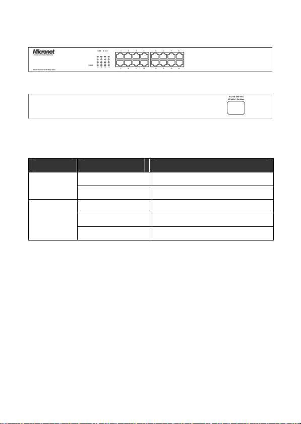
Physical Description
SP616R front view
SP616R rear view
Please refer to the following table for LED definition
LED Status Operation
Power
LINK/ACT
Steady Green Power is on
Off Power is off
Steady Green A valid link is established
Off No link is established
Blinking Green Transmitting or receiving data
3
Page 5
Installation
Micronet SP616R Switches do not require software configuration.
Users can immediately use any of the features of this product simply
by attaching the cables and turning on the power.
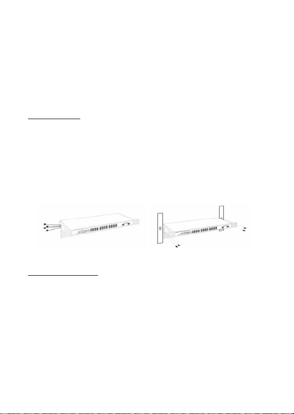
Rack Mounting
The switch can be mounted in an EIA standard 19-inch rack, which
can be placed in a wiring closet with other equipment. Attach the
mounting brackets at the switch’s front panel (one on each side),
and secure them with the provided screws.
Then, use screws provided with the equipment rack to mount each
switch in the rack.
Station Connections
Connect each station to the switch by twisted-pair cable. Plug one
RJ-45 connector into a RJ-45 port of the switch, and plug the other
RJ-45 connector into the station’s network adapter. Power on the
switch and then system is ready.
It supports Auto-Negotiation function to automatically select optimal
4
Page 6

speed (10/100Mbps) and mode (Full/Half Duplex). If the attached
device does not support auto-negotiation or has auto-negotiation
disabled, an auto-sensing process is initiated to select the speed
and set the duplex mode to half-duplex.
Switch-to-switch Connections
In making a switch interconnection, you could use any port to
connect another switch with straight or crossover cable. As all the
ports support auto-uplink (MDI / MDI-X) function, using a
straight cable to make a switch-to-switch connection is
allowed.
Cable Selection
Refer to the following table:
Network Speed Cable Type Max. Length
10Mbps Cat. 3, 4, 5 UTP/STP 100 meters
100Mbps Cat. 5 UTP/STP 100 meters
Note: To prevent costly equipment damage and downtime, please
consider installing a surge suppression device or a UPS
(Un-interrupted Power Supply).
5
Page 7

Network Application
6
Page 8

Specifications
Standard
Interface 16 * RJ-45 ports (10/100Mbps)
Cable Connections
Network Speed
Features Auto-negotiation, Auto Uplink
Switch Fabric 3.2Gbps
Memory 4 MByte
MAC Address Table 8K entries
Forwarding Method Store and Forward
Filtering/Forwarding
Rate
Emission FCC Class A, CE
Operating Temperature 0 o ~ 55 o C (32 o ~ 131
Operating Humidity 10% - 95% (Non-condensing)
Dimension & Weight 441 x 130 x 44 mm, 1.34kg
Power Supply
IEEE802.3, IEEE802.3u
IEEE802.3x : Flow Control
10BASE-T: Category 3, 4, 5 UTP/STP
100BASE-TX: Category 5 UTP/STP
20M(Full duplex)/10M(Half duplex)
200M(Full duplex)/100M(Half duplex)
10Mbps: 14,880pps/14,880pps
100Mbps: 148,800pps/148,800pps
o
F)
100 - 240V AC, 50/60 Hz
Full range internal power supply
7
Page 9

FCC Certifications
This Equipment has been tested and found to comply
with the limits for a Class A digital device, pursuant to
part 15 of the FCC Rules. These limits are designed to provide
reasonable protection against harmful interference when the
equipment is operated in a commercial environment. This
equipment generates, uses, and can radiate radio frequency energy
and, if not installed and used in accordance with the instruction
manual, may cause harmful interference to radio communications.
Operation of this equipment in a residential area is likely to cause
harmful interference in which case the user will be required to
correct the interference at his own expense.
This device complies with Part 15 of the FCC Rules. Operation is
subject to the following two conditions: (1) this device may not cause
harmful interference, and (2) this device must accept any
interference received; including interference that may cause
undesired operation.
8
Page 10

CE Mark Warning
This equipment complies with the requirements
relating to electromagnetic compatibility, EN 55022
class A for ITE, the essential protection requirement of Council
Directive 89/336/EEC on the approximation of the laws of the
Member States relating to electromagnetic compatibility.
Company has an on-going policy of upgrading its products and it
may be possible that information in this document is not up-to-date.
Please check with your local distributors for the latest information.
No part of this document can be copied or reproduced in any form
without written consent from the company.
Trademarks:
All trade names and trademarks are the properties of their
respective companies.
Copyright © 2004, All Rights Reserved
P/N: 2300-0233
9
Page 11

Appendix
A. Fast Ethernet Technology
The growing importance of LANs and the increasing complexity of
desktop computing applications are fueling the need for high
performance networks. A number of high-speed LAN technologies
have been proposed to provide greater bandwidth and improve
client/server response times. Among them, 100BASE-TX (Fast
Ethernet) provides a non-disruptive, smooth evolution from the
current 10BASE-T technology. The non-disruptive and smooth
evolution nature, and the dominating potential market base,
virtually guarantees cost effective and high performance Fast
Ethernet solutions in the years to come.
100Mbps Fast Ethernet is a new standard specified by the IEEE
802.3 LAN committee. It is an extension of the 10Mbps Ethernet
standard with the ability to transmit and receive data at 100Mbps,
while maintaining the CSMA/CD Ethernet protocol. Since the
Switch is compatible with all 10Mbps Ethernet environments, it
provides a straightforward upgrade and takes advantage of the
existing investment in hardware, software, and personnel training.
B. Switching Technology
Another approach to pushing beyond the limits of Ethernet
technology is the development of switching technology. A switch
bridges and transmits Ethernet packets at the MAC address level
of the Ethernet protocol, among connected Ethernet or Fast
Ethernet LAN segments.
10
Page 12

Switching is a cost-effective way of increasing the total network
capacity available to users on a local area network. A switch
increases capacity and decreases network loading by dividing a
local area network into different segments. Each segment has its
own bandwidth and it does not compete with others for network
transmission capacity.
A switch acts as a high-speed selective bridge between the
individual segments. The switch forwards traffic from origin
segment to destination segment, without interfering with any other
segments. By doing this, the total network capacity is multiplied,
while still maintaining the same network cabling and adapter cards.
For Fast Ethernet networks, a switch is an effective way of
eliminating problems of uplinking Fast Ethernet hubs beyond the
“two-repeater limit”. A switch can be used to split parts of the
network into different collision domains, making it possible to
expand your Fast Ethernet network beyond the 205-meter network
diameter limit. The switch supports both traditional 10Mbps
Ethernet and 100Mbps Fast Ethernet, which is also ideal for
bridging between the existing 10Mbps networks and the new
100Mbps networks.
LAN Switching technology is a marked improvement over the
previous generation of network bridges, which were criticized by
their higher latencies. Routers have also been used to segment
local area networks. But, the router expensive, difficult to setup,
and maintenance intensive, these make it relatively impractical for
11
Page 13

the network. Switch, on the other hand, is less expensive, easier to
setup, and practically maintenance free, which make it an ideal
solution to today’s local area network congestion problems.
C. RJ-45 Pin Assignment
According to the EIA/TIA 586B standard, the color sequence of
Cat.5 UTP is as following figure. The Straight-through cable is used
to connect between switch and PC. The Cross-over cable is used
to connect between two switches without auto uplink (auto
MDI/MDI-X).
12
Page 14

Contact Media Direct Interface Signal
1 TX + (transmit)
2 TX - (transmit)
3 Rx + (receive)
4 Not used
5 Not used
6 Rx - (receive)
7 Not used
8 Not used
13
 Loading...