

Page 1

User’s Manual
Internet IP Telephone
Model No.: SP5100
Website: http://www.micronet.info
Version 3.0
Page 2

Table of Contents
1 INTRODUCTION....................................................................................................................................... 3
1.1 PRODUCT DESCRIPTION...................................................................................................................... 3
1.2 APPEARANCE ..................................................................................................................................... 5
1.3 SPECIFICATION OF CONNECTOR........................................................................................................... 8
2 OPERATING PROCEDURE – LCD DISPLAY......................................................................................... 9
2.1 INITIALIZE SP5100 IP PHONE.............................................................................................................. 9
2.2 LCD CONFIGURATION....................................................................................................................... 10
3 WEB CONFIGURATION ........................................................................................................................ 17
3.1 NETWORK CONFIGURE...................................................................................................................... 19
3.2 H323 CONFIGURE ............................................................................................................................ 21
3.3 SYSTEM CONFIGURE ........................................................................................................................ 23
3.4 PPPOE CONFIGURE ......................................................................................................................... 24
3.5 DDNS CONFIGURE........................................................................................................................... 25
3.6 VOICE CONFIGURE (FOR ADVANCED USER) ....................................................................................... 26
3.7 TONE CONFIGURE (FOR ADVANCED USER) ........................................................................................ 27
3.8 BUREAU CONFIGURE ........................................................................................................................ 28
3.9 SUPPORT FUNCTIONS (BOTH SIDE MUST SUPPORT) ............................................................................ 29
3.10 DSCP CONFIGURE........................................................................................................................... 30
3.11 PHONE BOOK (FOR PEER-TO-PEER MODE ONLY) ............................................................................... 31
3.12 PASSWORD ...................................................................................................................................... 32
3.13 FIRMWARE UPGRADE........................................................................................................................ 33
3.14 SYSTEM COMMAND........................................................................................................................... 34
3.15 VERSION INFORMATION..................................................................................................................... 35
4 UPGRADE THE SP5100 IP PHONE...................................................................................................... 36
4.1 LCD PANEL CONTROL ...................................................................................................................... 36
4.2 REMOTE CONTROL: TELNET.............................................................................................................. 37
4.3 WEB MANAGEMENT .......................................................................................................................... 38
5 ADVANCED CONFIGURATIONS VIA TELNET .................................................................................... 39
5.1 [HELP] COMMAND .............................................................................................................................. 39
5.2 [QUIT] COMMAND............................................................................................................................... 40
5.3 [REBOOT] COMMAND ......................................................................................................................... 40
5.4 [FLASH] COMMAND ............................................................................................................................ 40
5.5 [COMMIT] COMMAND.......................................................................................................................... 41
1
Page 3

5.6 [IFADDR] COMMAND........................................................................................................................... 41
5.7 [TIME] COMMAND............................................................................................................................... 42
5.8 [PING] COMMAND .............................................................................................................................. 43
5.9 [PBOOK] COMMAND ........................................................................................................................... 43
5.10 [DDNS] COMMAND ............................................................................................................................. 44
5.11 [PPPOE] COMMAND ........................................................................................................................... 45
5.12 [SYSCONF] COMMAND ....................................................................................................................... 46
5.13 [H323] COMMAND ............................................................................................................................. 47
5.14 [VOICE] COMMAND ............................................................................................................................ 50
5.15 [TOS] COMMAND................................................................................................................................51
5.16 [TONE] COMMAND ............................................................................................................................. 53
5.17 [SUPPORT] COMMAND ....................................................................................................................... 54
5.18 [BUREAU] COMMAND ......................................................................................................................... 54
5.19 [ROM] COMMAND............................................................................................................................... 55
5.20 [PASSWD] COMMAND ......................................................................................................................... 56
5.21 [RBTONE] COMMAND ......................................................................................................................... 57
2
Page 4

1 Introduction
SP5100 IP Phone is a full-featured IP-based telephone system, which provides VoIP
service on LAN or any IP based environment. By using IP environment for voice
communication, company or individual can save lots of expenses and make data and voice
network converged.
SP5100 IP Phone also supports PSTN analog line connection. Therefore, it can perform as
the same as traditional POTS (Plain Old Telephone Service).
1.1 Product Description
Features and Specification
Basic Features:
● ITU-T H.323 v3 compliance
● DTMF detection/generation
● TFTP/FTP software download
● Remote configuration/reset via Telnet
● LED indication for system status:Speaker, Hold ,Mute , Message , PSTN
● Network Interface :
● Switch Hub inside, providing 2 RJ-45 sockets for 10/100Base-T connection
● 1 RJ-11 socket for PSTN connection
● Microsoft Net Meeting v3.0 compatible
● SNTP (Simple Network Time Protocol)
● Call HOLD/TRANSFER/FORWARD/MUTE
● PSTN/IP side access switch
● 10 Direct Line Button for speed dial
● Speaker Mode
● System Configuration from keypads and displayed on LCD
● Ring Tone selection
● Password setting for security
● Function Keys : Speaker , Redial , Mute , Hold , Transfer , Forward , Message ,
PSTN
● Ten sets last Phone Number redial
● Dial plan
● Provide ToS (Type Of Service) function
● Gatekeeper mode or Peer to Peer mode selection
3
Page 5

Caller ID:
● IP side display H323-ID and E.164.
● Display the count of total call received.
● Display un-answered call name, number.
● Show caller’s name, number, calling time.
Volume Adjustment:
● Speaker volume level adjustable.
● Handset Receiver volume level adjustable.
LCD:
● lines, 24 character Dot Matrix display.
● Indicator messages of HOLD, MUTE, PSTN, Directed Line 1~10.
● Display current date and time.
● Display of call duration.
Audio features:
● Codec -- G.711 a/µlaw, G.723.1 (6.3Kbps),G.729, G.729a
● VAD (Voice Activity Detection), CNG (Comfort Noise Generate)
● G.168/165-compliant adaptive echo cancellation
● Dynamic Jitter Buffer
● Bad Frame Interpolation
● Provide H.245 Out-band DTMF message
● Call Transfer (H.450.2)
● Call Forward (H.450.3)
● Call Hold (H.450.4)
● Gain (Voice Volume) Settings
● Provide Call Progress Tone: Dial tone, busy tone, call-holding tone and ring-back
tone
Firmware Upgrade:
● Firmware version displayed on LCD.
● Two ways to upgrade firmware:
- Download by KEYPAD configuration.
- Download by Telnet.
Management Features:
● SP5100 IP Phone KEYPAD
● TELNET
● Web Browser
4
Page 6

1.2 Appearance
1. Front View and Keypad function
● C: Cancel and Clear
● ÍÎ : Move to left /previous and right / next.
● OK: Press OK to confirm the modification.
● Direct Line (DL) Button 1 – 10: User press DL button to do speed dial according
to phone book data 1-10 (please refer to LCD configuration-Phone Address Book
or Advanced Configurations via Telnet-[pbook] command ).
● Number 1 –10, * and #: The function is as the same as the general phone set.
Corresponding list of keypad and symbol:
1 “Space” ; “,” ; “.” ; “!” ; “1”
2 “A” ; “ B” ; “C” ; “2”
3 “D” ; “E” ; “F” ; “3”
4 “G” ; “H” ; “I” ; “4”
5 “J” ; “K” ; “L” ; “5”
6 “M” ; “N” ; “O” ; “6”
7 “P” ; “Q” ; “R” ; “S” ; “7”
8 “T” ; “U” ; “V” ; “8”
5
Page 7

9 “W” ; “X” ; “Y” ; “Z” ; “9”
* “-“ ; “?” ; “*”
0 “0”
# “_” ; “@” ; “#”
● MUTE: Mute the voice of MIC and let others can’t hear from user in communication.
● PSTN: Press PSTN to switch SP5100 IP Phone as PSTN or IP Phone Mode. In
PSTN mode, “PSTN” characters will be displayed on LCD left bottom side, then
users can dial out as if standard telephone set in PSTN; in IP Phone mode, “GK”
characters will be displayed on LCD left bottom side.
Note:
1. When IP Phone is in PSTN mode, only PSTN and SPEAKER function key can work.
2. On LCD will display”….Incoming Call…. ” to notice user when IP Phone has both IP
and PSTN side incoming calls.
3. If in communication with IP side, user can press HOLD to hold IP side, then press
PSTN to pick up PSTN side, after that can press HOLD again to retrieve IP side.
4. If in communication with PSTN side, user must hang up PSTN side before pick up IP
side.
● HOLD: To hold a call with H.450 function.
● SPEED: Press SPEED and number (Phone book index) to do speed dial according
to phone book data (please refer to LCD configuration-Phone Address Book or
Advanced Configurations via Telnet-[pbook] command).
● FORWARD: Forward a incoming call to another IP device by H.450 forward
function.(please refer to LCD configuration-Indicate Forward Type)
● MESSAGE and its indicated LED light: When missing the incoming calls, the
message LED will be flashing. User can know the information of miss call by
pressing the message button.
● TRANSFER:
1. Transfer a call by H.450 transfer function. Press TRANSFER button in
communication and press phone No. which user want to transfer to can transfer this
call.
2. Change characters to be capital or lowercase: when press TRANSFER before
press letters can switch type of letters.
● REDIAL: Redial the last outgoing call.
● + and - : Adjust the voice volume in communication.
● SPEAKER: Speaking without picking up handset.
6
Page 8
Note
:
All fu
nction keys mentioned above (except Number 1 –10, * and # ) are effective only in IP
Pho
ne mode.
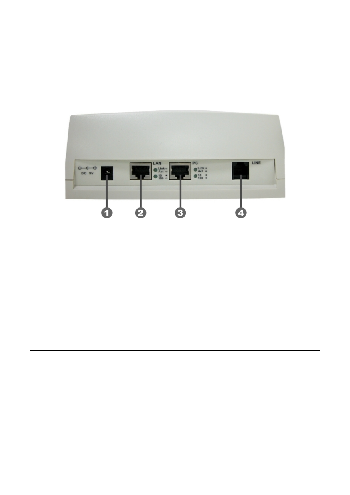
2. Back View
n DC 9V: DC 9V power input outlet
o LAN: RJ-45 connector, connected directly to the Hub through the straight CAT-5
cable.
p PC: RJ-45 connector, connected directly to the PC through the straight CAT-5
cable
q Line: RJ-11 connector, connected directly to the PSTN analog line.
Note:
There are two LED indicated lights: LINK/ACT and 10/100 for LAN port and PC port. When
network status is in normal, LED of LINK/ACT will be flashing; when transmit rate is in 10
mbps/100mbps, LED of 10/100 will light off/on.
7
Page 9
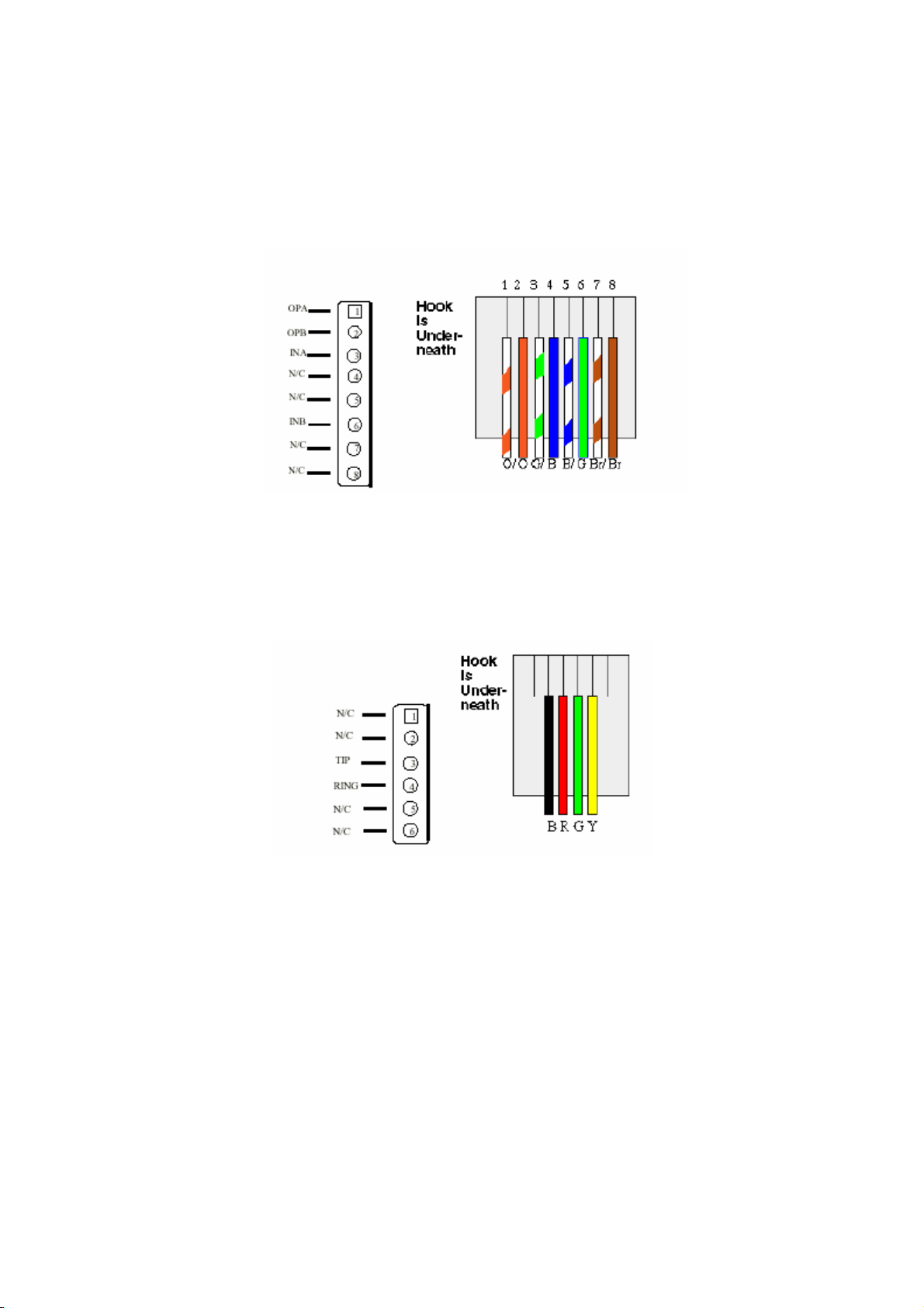
1.3 Specification of connector
1、 Ethernet Port:
Ethernet port is for connecting IP Phone to network, transmit rate supports 10/100
Base-T.
Ethernet connector(LAN)
2、 RJ11connector:
RJ11 connector is for connecting IP Phone with PSTN.
RJ11connector
8
Page 10

2 Operating Procedure – LCD Display
2.1 Initialize SP5100 IP Phone
1. When power on the SP5100 IP Phone, the LCD screen shows as below.
IP
-Phone
Bo
ard Start Booting
2. Wait around one minute until the SP5100 IP Phone finishes boot program
initialization.
3. User can see flashing greeting as below:
Sy
stem Initializing………
4. Then IP Phone get into standby mode:
IP
-Phone
GK
10:10:10 AM
The main LCD screen would be shown as similar as above. The GK word means the
SP5100 IP Phone is in Gatekeeper Mode, and when IP Phone is connected to SNTP
server, on LCD will show current time from SNTP server.
5. fter pressing the PSTN button, the GK word will be replaced by PSTN. Then IP
A
Phone is in PSTN Mode. Please notice that in PSTN mode user must plug PSTN li
in RJ-11 port.
IP-Phone
PSTN 10:10 AM
Press Í or Î to enter configur mode then press OK Bottom to enter certain menu.
There are 6 selections for configuration.
10:
ation
ne
1. System Configuration (mandatory, protected by password)
2. User Line Number (mandatory
3. Ring Configuration
4. Indicate Forward Type
5. Message Box
6. Phone Address Book
)
9
Page 11

Note:
CD Panel of SP5100 IP Phone is operated manually by moving Í or Î on the keypad.
L
Pres enter separate configuration menu. Press C to go back to the main menu.
s OK to
2.2 LCD
User can set the following 10 configurations manually by operating the commands
displayed on LCD.
Note:
Any configurations th
e selection 1→5 “Reboot”.
th
System Configuration (mandatory, protected by password)
z Please Enter Password
Note:
1. Pas
Configuration
at have made for the SP5100 IP Phone, user has to do Reboot in
:
User must key in password to enter this menu, selections under this
command are all important ones, which can on
administrators.
sword to enter System Configuration:
ly be configured by
2. H.323 token password (please refer to item 9), default value is x. (Please press
ANSFER button to switch as lowercase characters first.)
TR
3. If users forget password, please contact us for the specific password generated
according to MAC address of IP Phone.
1
. Connect Configuration
There are ten sub-configurations included in Connect Configuration. It is
necessary for user to set it in order to run the SP5100 IP Phone correctly.
In addition, user has to prep
environment. (Global public IP Address or Virtual IP Address)
(1) IP address
In this configuration mode, user presses the prepared IP Address on th
IP Phone keypad. Please input IP address as format: xxx
(2)
Subnet Mask:
User has to press the subnet mask IP Address on the IP Phone keypad
are one valid IP Address to meet your network
e
.xxx.xxx.xxx.
.
10
Page 12

(3) Gateway
User has to press the default gateway IP which meets IP Address on the
IP Phone keypad.
(4)
Primary DNS
User can set IP add
nd Phone book can enter URL address or IP address. Please refer to 5.9
a
[pbook] and 5
ress of Domain Name Server, then for Gatekeeper
.13 [h323] command.
(5)
Secondary DNS
User can set IP address of secondary
ork normally, IP Phone can refer to secondary DNS.
w
DNS, once primary DNS cannot
(6)
Gatekeeper
User has to offer one available Gatekeeper server IP A
Address on the IP Phone keypad.
IP
ddress and set this
(7)
Second Gatekeeper
IP Phone provide alternative Gatekee
Main Gatekeeper for 10 times, it will try to register to the Second
to
Gatekeeper. When m
ain Gatekeeper can’t work normally, IP Phone can
per feature, if IP Phone can’t register
still keep working with Second Gatekeeper
(8)
SNTP Configuration
SP5100 IP Phone supports that user can as
etwork Time Protocol) Server in your country by setting in IP Phone.
N
User has to offer one
available SNTP server IP Address and set this IP
sign one SNTP (Simple
Address on the IP Phone keypad.
(A) SNTP Mode: User can set different time can set SNTP function too b
on/off/broadcast, which means
IP Phone will capture current time
from SNTP server or not, or broadcast to find a SNTP server and
capture current time.
(B)
SNTP Server: User can specify a SNTP server for IP Phone to
capture current time.
(C) et time zone according to the location IP
Time Zone: User can s
Phone is. For example, in Taiwan the time zone should be set a
e
s
11
Page 13

8,which means GMT+8.(user can press “*” as “-“)
Note:
If user d t time.
idn’t set SNTP server, on LCD won’t display curren
(9) Conn
ection Mode
There are 2 types for SP5100 IP Phone to connect to the other de
They are GK, P2P. The default mode is in GK mode. When user would like
to connect via P2P
mode, the SP5100 IP Phone must change as well.
Move the “~” symbol by press Í or Î on the keypad to select one mode
(10
) DHCP Mode (ON/Off)
User can set IP Phone in DHCP mode, which means IP Phone will get a
ynamic IP automatically.
d
(11
) Token Password
(A) LCD menu password:
User can enter LCD system configuration by
key in this password
(B) H.235 securit
y: To set RRQ/ARQ authentication token password. If
IP Phone wants to register to a Gatekeeper, which implement H.235
vices.
.
security token feature
, IP Phone has to set a RRQ/ARQ
authentication token password, which is provided by Gatekeeper
manager. IP Phone can’t work normally with this Gatekeeper unless
Token Password is set.
(12) GR
Q Option
To set auto discovery function OFF or ON. If this function is enabled and
IP address of Gatekeeper is set as 255.255.255.255, IP Phone will
multicast to s
earch a Gatekeeper on network with configured
Gatekeeper ID (please refer to (13) Gatekeeper ID); if IP address of
Gatekeeper is set, before IP Phone register to the assigned Gatekee
it will send out GRQ (Gatekeeper Request) message with con
figured
per,
Gatekeeper name to Gatekeeper first.
(13)
Gatekeeper ID
To set Gatekeeper name for Gatekeepe
r discovery. When IP Phone
send out Gatekeeper discovery message will search Gatekeeper with
this Gatekeepe
r name
12
Page 14

2. User
Line Name
User has to identify one ID name for the SP5100 IP Phone to register to the
Gatekeeper.
3.
Firmware Update
(1) Downloa
d method
There are two methods to download new rom file, please move the “~”
symbol by press
then press OK to co
(2)
Set File Server IP
User has to offer one TFTP/FTP server IP Address and set this IP Addres
on the IP Phone keypad. The
Phone new applica
(3)
Set FTP user account
Í or Î on the keypad to select TFTP or FTP method,
nfirm it.
s
IP Address is necessary for upgrading IP
tion rom file.
User has to press user name and password for FTP server login .It is
necessary for upgrading IP Phon
e’s new application rom file in FTP
method.
(4)
Indicate file name
User has to press the file name of new application rom file prepared for
upgrading
(5) Start Download
Press OK to start download new application rom file. After download is
finished, IP
(6) Firmware Versio
Phone will automatically reboot.
n
Show versions of all rom files and hardware.
Note
:
1. Download via LC
D command can only upgrade new application
rom file.
IP Phone fails to upgrade via LCD menu, IP Phone will
2. If
automatically reboot.
4. Ha
rdware Test
SP51 elf-test for all functions buttons. Please follow the
00 IP Phone provides s
direction from LCD panel to operate and verify it.
5.
PPPoE Configuration
(1) PPPoE Mode
13
Page 15

Choose ON or OFF to enable or disable PPPoE function.
(2) Username And Pass
To set PPPoE
(3)
Retry When Disconnect
Choose ON or OFF to ena
function, after PPPoE being disconnected, IP Phone w
reboot to re-connect, and
with server, IP Phone will keep trying to connect. On the other hand, if
users disable this function, IP Phone won’t reboot and keep trying to
connect.
6. Reb
2. User Li
User has to 5100 IP Phone to register to the
Gatekeeper. User can set up to 10 different numbers.
oot
It is necessary and important for user to reboot it after any configurations has
been made to the SP5100 IP Phone.
ne Number
identify at least one number for the SP
connection user name and password.
word
ble or disable this function. If users enable this
ill automatically
after reboot, if IP Phone still can’t get contact
3. Ring Co
(1) Line Num
(2) Line Number 2
(3) Line Number 3
(4) Line Number 4
(5) Line Number 5
(6) Line Number 6
(7) Line Number 7
(8) Line Number 8
(9) Line Number 9
(10) Line Number 1
Note:
User can set six zero
number after this one. Ex. Line Number 1-5 are configured, if user set Line 3
as “0000
ber 1
0
“000000” on LCD to disable this number and the
00”, Line number 3-5 will be disabled.
nfiguration
(1) Ring Style Selection
There are three tone styles for SP5100 IP Phone. Move the “~” symbol by
pressing Í or
Î on the keypad to select the tone style preferred. Then press
14
Page 16

OK to confirm it.
(2)
4. Indicate
There are two selections to activate or deactivate forward function. After selection
please press OK
i. Activate: choose under which situation to forward call to another endpoint.
Choose Tone Style:
Low Middle High
Ring Volume Control
User can adjust ring volume by pressing Í or Î on the keypad to decrease
or increase volume.
Forward Type
After selection please press OK, then enter LINE NUMBER of another
endpoint prepared to forward to.
A. Busy
When SP5100 IP Phone is in
directly forwarded to the assigned phone number.
busy status, the incoming call will be
ii. Deac ter
5. Mess
If there n message box . MESSAGE LED
will be flashing until user press MESSAGE to check miss call and re-press
B. No respo
When SP5100 IP Phone is continuing ringing around 10 seconds, th
incoming call will be directly forwarded to the assig
C. Unconditional
It is included the above two types. Whether the IP Phone is in which
status, it will be automatically forwarded to the assigned phone number.
tivate: choose under which situation to deactivate forward function. Af
selec
tion, please press OK, then user can see LINE NUMBER of the
endpoint which is already configured to forward to, now press OK again.
Note: The number that user prepares to forward to is E.164 number
which is registered on the Gatekeeper.
nse
ned phone number.
age Box
is an unanswered IP call, it will be kept i
e
MESSAGE to
• New Call:to see all incoming-call records in message box.
• History:to see all records in message box.
return to main screen.
15
Page 17

6. Phone A
ddress Book
• Display
Display all name and telephone number recorded to the phone address
book.
• Add
Add and save name, telephone number and IP address of the phone
addres
• Edit
Edit name, telephone number, and IP address of Phone book.
•
Delete
Delete
N key in IP address in Pbook table, please do not add 0
ote: When
before IP address (ex.10.1.1.1 please do n
010.001.001.001).
7. PPPoE Inform
s book.
the record in the phone address book.
ot key in
ation
All items below can hen PPPoE connection is established, user can
heck related information here.
c
only be displayed w
• PPPoE Status
• Note Information
• PPPoE IP addres
• Destination Host
s
• DNS Primary
• Subnet Mask
• Authentication
• Protocol
• Device
16
Page 18
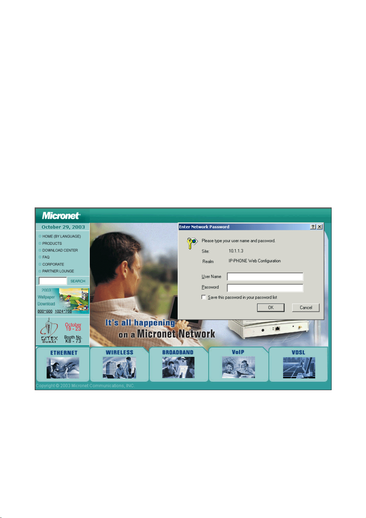
3 Web Configuration
The initial version for HTTPD web management interface provides user to configure easily
rather than command operating method through RS-232 / TELNET.
The configuration function and step is similar with the way through command line. Basically
this version is not the finalized version for web interface. Initially please refer to the manual
for more information. Below provide a simple user guide for user to configure via web
interface. Next version for HTTPD web management will not like the command format, but
friendly interface.
Step1. Browse the IP Address predefined via Keypad or TELNET
Step2. Input the login name and password
● Login name: root / administrator
● Password: None (just press Enter in default value)
17
Page 19

Step 3. The web interface main screen
Step 4. Start configure
Most of all commands displayed in console / telnet are transfer to web interface. The most
important commands are Network Interface, H323 Information, Commit Data and Reboot
System. The method is as the same as command mode.
18
Page 20

3.1 Network Configure
- DHCP: Enable / Disable to DHCP mode
- IP Address: Set IP Address
- Subnet Mask: Set the Subnet Mask
- Default gateway: Set Default routing gateway
- Domain Name Server: Set Domain Name Server IP address
- SNTP: Enable / Disable the Simple Network Time Protocol
- SNTP Server Address: Set SNTP Server Address
- GMT: Set time zone for SNTP Server time
- IP Sharing: Enable it if behind IP Sharing router
- IP Sharing Server Address: Set WAN IP Address of IP Sharing Server router if it is a
fixed one.
- IP Change Feature: enable/disable IP change Function
- Web Configure Server Port: set http port for configuration via web browser
Please be noted:
If the WAN IP Address of IP Sharing Server router is not a fixed one, it is not necessary
19
Page 21

to input any values.
If behind the dynamic WAN IP Address situation please configure as GK mode and
select special Gatekeeper, please refer to your vendor.
20
Page 22

3.2 H323 Configure
- Mode: Select GK mode or Peer-to-Peer mode
- Gatekeeper IP Address: Set Gatekeeper IP Address
nd
- 2
Gatekeeper IP: Set Redundancy Gatekeeper IP Address
- Gatekeeper Id: Set Gatekeeper ID
- Gatekeeper Discovery: Enable/Disable GRQ function
- Registered E.164 Number-01: Set 1
- Registered E.164 Number-02: Set 2
- Registered E.164 Number-03: Set 3
- Registered E.164 Number-04: Set 4
- Registered E.164 Number-05: Set 5
- Registered E.164 Number-06: Set 6
- Registered E.164 Number-07: Set 7
- Registered E.164 Number-08: Set 8
- Registered E.164 Number-09: Set 9
- Registered E.164 Number-10: Set 10
st
phone number
nd
phone number
rd
phone number
th
phone number
th
phone number
th
phone number
th
phone number
th
phone number
th
phone number
th
phone number
- Registered H.323 ID: Set Registered Alias as H323 ID
21
Page 23

- Token Password: Set Token password for H.235 security use
- RTP Port Time to Live (TTL) Gatekeeper finding port RAS Port
Response Timeout Connection Timeout: For Advanced User only
22
Page 24

3.3 System Configure
- Keypad Type: Select different DTMF Keypad Type (For Advanced User)
- Dial Plan: Set DTMF digit limitation (0 is for any digits)
- Call Alive: Enable the function to check connection (Both side must support)
- Inter Digit Time: Set the DTMF inter digit time (second)
- Digit Type of End of Dialing: Select end of dialing type as none, OK, #, or * .
- H.450 Related Features: Enable/Disable H.450 function.
23
Page 25

3.4 PPPoE Configure
- Device: Enable/Disable PPPoE function
- User Name: Set PPPoE Connection User Name
- Password: Set PPPoE Connection password
- Reboot After Remote Host Disconnection: Enable/Disable auto reboot after PPPoE
disconnection
- Other items: After PPPoE connection established, related information will be
displayed
24
Page 26

3.5 DDNS Configure
- Status: to enable/disable DDNS function
- Server: to choose one DDNS server, on which user has already registered. (Now
only one DDNS server is available---www.dyndns.org)
- Localhost Name: to set the registered Domain Name of IP Phone
- User ID: to set login ID of registered account to log in DDNS server
- User Password: set password of registered account to log in DDNS server
- Check Host Current IP Address: to enable/disable check IP function. If IP Phone is
behind IP sharing, when this function is enabled, IP Phone will check its public IP
address by asking IP address check server and send to DDNS server to update
DDNS data. If this function is disabled, when IP Phone is behind IP sharing, it will
send it’s private IP address to DDNS server
- Primary Service Server: to set IP address check server
- Secondary Service Server: to set secondary IP address check server
- Check every minutes hours off: to set the update interval time. IP Phone will
re-update its IP address in this time.
25
Page 27

3.6 Voice Configure (For Advanced User)
- Codec Priority: It got wrong order with “Frame Size”. Select the packet size in
sending process. (For Advanced User)
- Sending Packet Size: Select the Codec Priority. (For Advanced User)
- G.723 Silence Suppression: Enable / Disable (For Advanced User)
- Volume: Adjust the volume in “Voice” (sending out); “Input” (receiving); “ DTMF”
(DTMF sending out) Please Noted the value is limited.
- Echo Cancel: Enable / Disable (suggested always Enable)
- Jitter Buffer: Min. Delay and Max. Delay (For Advanced User)
26
Page 28

3.7 Tone Configure (For Advanced User)
- Busy Tone
- Reorder Tone
- Ring Tone 1
- Ring Tone 2
- Dial Tone
Set the above tone Frequency, Level and On/Off time
27
Page 29

3.8 Bureau Configure
- Hold Tone Generation (using PCM file): Enable/Disable hold tone generation
28
Page 30

3.9 Support Functions (Both side must support)
- Fast Start: Enable to do Fast Start
- H.245 Tunneling: Enable to open H.245 Tunneling
- H.245 Separate Channel: Enable/Disable open H.245 channel after fast start
connection
29
Page 31

3.10 DSCP Configure
Set Signal or RTP Packet DSCP value:
- Assured Forwarding (AF) PHB: Select Delay priority and Drop Precedence
- Expedited Forwarding (EF) PHB: Select ToS value as EF
- Default: Select ToS value as 0
- User Assign Special DSCP Code: User can set other unspecified value here.
30
Page 32

3.11 Phone Book (For Peer-to-Peer mode only)
User can specify 20 sets of phone book via web interface. Input the Name, IP Address
and E.164 No. of the destination device.
31
Page 33

3.12 Password
First select login name as root or administrator, then enter current password , new
password and confirm new password again.
32
Page 34

3.13 Firmware Upgrade
- TFTP Server IP Address: Set TFTP server IP address
- Target File name: Set file name prepared to upgrade
- Method: Select download method as TFTP or FTP
- FTP Server IP Address: Set FTP server IP address
- FTP Login: Set FTP login name and password
- Target File Type: Select which sector of IP Phone to upgrade
33
Page 35

3.14 System Command
Press CLEAN will clean all configurations of IP Phone and reset to factory default value.
Please be noted: Once execute this function, user must re-configure all commands all
over again.
Press reboot will reset IP Phone.
34
Page 36

3.15 Version Information
Display current version list.
35
Page 37

4 Upgrade the SP5100 IP Phone
SP5100 IP Phone supports three methods to upgrade the new version. All methods are
necessary to prepare the TFTP program on the host PC as TFTP server. After installing
TFTP program on one PC and connecting to network, SP5100 IP Phone is ready to be
upgraded.
4.1 LCD Panel Control
1.Choose the 1→3 selection-Firmware Upgrade. Press OK to enter into the
sub-selection as below.
2. Download method
There are two methods to download new rom file, please move the “~” symbol
by press Í or Î on the keypad to select TFTP or FTP method, then press OK
to confirm it.
3. Set File Server IP
User has to offer one TFTP/FTP server IP Address and set this IP Address on
the IP Phone keypad. The IP address is necessary for upgrading IP Phone new
application rom file.
4. Set FTP user account
User has to press user name and password for FTP server login .It is
necessary for upgrading IP Phone new application rom file in FTP method.
5. Indicate file name
User has to press the file name of new application rom file prepared for
upgrading
6. Start Download
Press OK to start download new application rom file .
7. Firmware Version
Show versions of all rom files.
Note:
• Download via LCD command can only upgrade new application
rom file.
• If IP Phone fails to upgrade via LCD menu, IP Phone will
automatically reboot.
36
Page 38

4.2 Remote Control: Telnet
• -print: show versions of all rom files.
• -app,-boot, -dsptest, -dspcore, -dspapp, -rbpcm and -htpcm: upgrade main boot
code, main application code, DSP testing code, DSP kernel code, DSP application
code, Ring Back Tone PCM file and Hold Tone .
• -s: it is necessary to prepare TFTP/FTP server IP address for upgrading rom file.
• -f: the file name prepared for upgrading is necessary as well.
• -server: specify TFTP/FTP server IP address. It is corresponding to LCD
configuration -firmware upgrade-Set file Server IP.
• -method: specify download method to be TFTP or FTP(0 for TFTP.1 for FTP)
• -ftp: specify user name and password for FTP download method
For example: User prepares to upgrade the latest app rom file – lp.505, the TFTP
server is 192.168.1.1.
rom -app -s 192.168.1.1 -f lp.505 (If -server is specified , can just type rom -app -f
lp.505)
37
Page 39

4.3 Web Management
- TFTP Server IP Address: Set TFTP server IP address
- Target File name: Set file name prepared to upgrade
- Method: Select download method as TFTP or FTP
- FTP Server IP Address: Set FTP server IP address
- FTP Login: Set FTP login name and password
- Target File Type: Select which sector of IP Phone to upgrade
38
Page 40

5 Advanced Configurations via Telnet
After initializing the SP5100 IP Phone IP Address setting (please refer to LCD Configuration:
1.Connect Configuration), user can enter into configuration mode via telnet.
Note:
● After user enter IP Phone configuration via telnet, please use login : ”root”,
password : ”press enter” to enter command line.
● Each command user must key-in with lower case, but contents of
configurations such as h.323 alias or user name etc, user can set as capital
case.
● User who changes any configuration needs to do the commit command then
reboot command.
5.1 [help] command
Type help, man or ? to display all the command lists. The following figure is shown all
commands of SP5100 IP Phone.
39
Page 41

5.2 [quit] command
Type quit / exit / close will logout SP5100 IP Phone and Telnet Program.
5.3 [reboot] command
After typing commit command, type reboot to restart the SP5100 IP Phone.
Sometimes after user type reboot, on terminal screen will display:
"Data modified, commit to flash rom?"
which means IP Phone will record call history or not.(ex. REDIAL , outgoing and
incoming call data)
5.4 [flash] command
This command will clean the configuration stored in the flash rom to default value and
reboot the SP5100 IP Phone.
Note: After user upgrade new software version, suggested to execute this command to
make sure new software work well on SP5100 IP Phone.
Note
:
To e d
xecute the command flash -clean, all configuration of SP5100 IP Phone store
on f
lash rom will be cleaned. It is authorized for the user whose login name is
“roo
t” only.
40
Page 42

5.5 [commit] command
Save any changes after configuring the SP5100 IP Phone.
5.6 [ifaddr] command
Configure and display the SP5100 IP Phone IP information.
• -ip, -mask, -gate: Set SP5100 IP Phone IP Address, subnet mask and default
gateway respectively.
• -dhcp: When DHCP function enables (ifaddr -dhcp 1), SP5100 IP Phone will
automatically search DHCP server after execute the commit and reboot
command.
• Note: After IP Phone catch a dynamic IP address form DHCP server, user can see
this IP address on LCD connect configuration.
• -sntp: When sntp server is available, enable SP5100 IP Phone SNTP function
and point to sntp server IP address. (ifaddr -sntp 1 “xxx.xxx.xxx.xxx”)
• -dns:User can set Domain Name Server IP address. Once IP Phone can connect
with DNS server, user can specify URL address instead of IP address for
Gatekeeper and phone book IP address. (Please refer to [h323] command and
[pbook] command)
• -timezone: User can set different time zone according to the location IP Phone is.
For example, in Taiwan the time zone should be set as 8, which means GMT+8.
(GMT-8: ifaddr -timezone -8)
• -ipsharing: If SP5100 IP Phone is behind a IP-sharing , user can enable IP
sharing function and specify public IP address.(ifaddr -ipsharing 0 / 1 “public IP
address of IP sharing” , 0 for disable and 1 for enable)
41
Page 43

• -ipchange: If user uses NAT device which support multiple public IP address, and
IP Phone enable IP change function, IP Phone will register to Gatekeeper with the
public IP that IP Phone uses but not the IP NAT uses.
• -http: set http port. User can configure IP Phone via web browser, default http port
is 80, if port 80 is not available or user has more than 1 IP Phone behind NAT, http
port can be changed to another available port.
5.7 [time] command
When sntp server is established as well as the sntp function of SP5100 IP Phone is
enabled, type time command should show the current time what is retrieved from the
assigned sntp server.
Note: Please refer to the [ifaddr] command to configure sntp server.
42
Page 44

5.8 [ping] command
Command ping can test which the IP address is reachable or not.
Usage: ping “xxx.xxx.xxx.xxx(IP address)”
The message will display packets transmitting condition or no answer from the IP
address.
5.9 [pbook] command
The command is for Peer-to-Peer Mode use only. Therefore, VoIP products such as
SP5100 IP Phone that support Peer-to-Peer Mode are also available to be addressed
on the SP5100 IP Phone phone book.
• -print: display phone book data. User can print all data in phone book by command
(pbook –print). Furthermore, user can also print only a section of data by indicating
parameter 'start_record' and 'end_record' (pbook –print “start prefix” “end prefix”). If
parameter 'end_record' is omitted, only record 'start_record' will be display
(pbook –print “start prefix”).
• -add: add a new record in phone book table by give a name and e164 number for
the Gateway / Terminal IP address .
(pbook –add name “X” ip “xxx.xxx.xxx.xxx” e164 “X”)
User can set IP or URL address (Domain Name Server must be configured. Please
refer to [ifaddr] command)
• -search: search any record such as ip address, name and e164 addressed on the
phone book.
• -delete: delete a record with index listed in phone book table. (pbook –delete “index
43
Page 45

number”)
• -insert: insert an record in specified index of phone book.
• -modify: modify any record that has addressed to index number. The name, IP
address and e164 number should be modified together in one modify command.
(pbook –modify “index” name “X” ip “xxx.xxx.xxx.xxx” e164 “X”)
Note: Please dial “#” after dial e.164 of pbook.
5.10 [ddns] command
This function is for Dynamic Domain Name Server service. Once users register to one
DDNS server, he can specify domain name for the IP Phone. When IP Phone reboot, it
will automatically update its IP address to DDNS server. In this way, even IP Phone is
using dynamic IP address, other endpoint can locate this IP Phone by its domain
name.
• -print: display DDNS overall information and configuration.
• -enable: to enable/disable DDNS function. (ddns –enable 0 / 1, 0 for disable and 1
for enable).
• -server: to set IP address of DDNS login server.
• -hostname: to set the registered Domain Name of IP Phone. (ex.
44
Page 46

ddns –lp001.ddns.org)
• -id: to set login ID of registered account to log in DDNS server.
• -passwd: to set password of registered account to log in DDNS server.
• -checkip: to enable/disable check IP function. If IP Phone is behind IP sharing,
when this function is enabled, IP Phone will check its public IP address by asking IP
address check server and send to DDNS server to update DDNS data. If this
function is disabled, when IP Phone is behind IP sharing, it will send its private IP
address to DDNS server.
• -checkipsrv: to set IP address of IP address check server.
• -delay: to set the update interval time. IP Phone will re-update its IP address in this
time. (ddns –delay 1-59m/1-24h , m means minute, h means hour)
• -force: to force to execute DDNS update. Once users enter this command, IP
Phone will update DDNS data immediately. (ddns –force “IP address of IP
Phone”)
Note:
1. For now we only support DDNS server as www.dyndns.org and www.3322.org.
2. User must register to DDNS server first, and specify user name and password in
ddns -id and ddns –passwd.
3. The default IP address of DDNS login server is member.dyndns.org and
members.3322.org.
4. User has to specify domain name applied for IP Phone in ddns –hostname.
5. The default IP address of check IP server in is checkip.dyndns.org.
5.11 [pppoe] command
• -print: display system overall information and configuration. IF IP Phone has
already connected to PPPoE server, user can see IP address and related
information with this command.
• -dev: to enable or disable PPPoE function. (pppoe –dev 0 / 1)
• -open: to open PPPoE connection (If IP Phone is not in PPPoE connection, user
can try to connect with pppoe -open)
• -close: to close PPPoE connection (If IP Phone is in PPPoE connection, user can
disconnect with pppoe -close)
• -id: to set PPPoE connection user name
• -pwd: to set PPPoE connection password
• -reboot: If user enable this function, after PPPoE being disconnected, IP Phone will
automatically reboot to re-connect, and after reboot, if IP Phone still can’t get
45
Page 47

contact with server, IP Phone will keep trying to connect. After re-connected, IP
Phone will also restart system. On the other hand, if users disable this function, IP
Phone won’t reboot and keep trying to connect. (pppoe –reboot 0 / 1)
Note: Firmware of IP Phone is separated into normal version and PPPoE version.
In Normal version has no ToS command.
5.12 [sysconf] command
This command displays the system information and configuration.
• -print: display system overall information and configuration.
• -plan: It is for setting dial numbering plan. While e164 number is three digits, the
plan should be set as 3 or 0. The plan 0 is for any positive digits use.
Note: Before change to Peer-to-Peer mode from GK mode, please remember to set
dial plan as 0, or it may works not normally in P2P mode.
• -keypad: set DTMF type .User can select DTMF type IP Phone receive and
transmit.(sysconf –keypad 0 / 1 / 2 / 3 , 0 for inband ,1 for H.245 alphanumeric,
2 for H.245 signal type, 3 for Q.931 user info, 4 for RFC2833.)
• -idto: set the duration (in second) of two pressed digits in dial mode as timed out. If
after the duration user hasn’t pressed next number, IP Phone will dial out all number
pressed.
• -eod: select end of dialing key, e.g set end of dial key as OK button , after finished
pressing dialing number then press OK will dial out. (sysconf –eod 0/1/2/3 , 0 for
no end of dial key , 1 for “OK” button , 2 for “#” button , 3 for “*” button )
• -h450: Enable or disable H.450 related features, which include transfer, hold and
forward.
46
Page 48

5.13 [h323] command
• -print: display H.323 stack information and configuration.
• -mode: configure SP5100 IP Phone as Gatekeeper or Peer-to-Peer Mode.
Usage: h323 –mode 0 / 1(0 for Gatekeeper mode,1 for Peer-to-Peer mode)
• -gk: set Main Gatekeeper IP address (h323 –gk “xxx.xxx.xxx.xxx”) or URL
address (Domain Name Server must be configured. Please refer to [ifaddr]
command) . User can set IP as 255.255.255.255 and let IP Phone auto discovery
for Gatekeeper. Please notice in this case, user must enable Gatekeeper discovery
function. Please refer to 5.-gkname and 10.-gkdis.
• -dfgw:to set IP address of default gateway, this function is the same as Microsoft
NetMeeting.
1. To implement this feature both calling and called endpoints must be under
peer-to-peer mode.
2. If the called party is FXO products, such as Micronet SP5050, which Have to
set sysconf –2nddial 0 to make one-stage dialing.
I. Dial remote PSTN number under default gateway, IP Phone will
automatically dial to default gateway, then default gateway will dial this
number to PSTN side.
II. For example, user wants to dial to ext.888 under Micronet SP5050, user
only have to dial 888 from IP Phone.
3. If called party is FXS products such as Micronet SP5004: user can dial line
number of Micronet SP5004 from IP Phone.
For example ,user wants to dial to Micronet SP5004, the configuration of
47
Page 49

SP5004 is h323 –line1 101/201 –line2 102,user can press 101/201 or 102
dialing to line1 or line2 of Micronet SP5004.
• -algk:set IP address or URL address( Domain Name Server must be configured.
Please refer to 6. [ifaddr] command) of alternative Gatekeeper. If IP Phone tries to
register to main Gatekeeper for 10 times but still fail, IP Phone will try to register to
alternative Gatekeeper.
• -gkname: set Gatekeeper name for Gatekeeper discovery. When IP Phone send
out Gatekeeper discovery message will search Gatekeeper with this Gatekeeper
name.(please refer to 10.-gkdis)
• -e164: identify one number for the SP5100 IP Phone to register to the Gatekeeper
(h323 –e164 “X”).
• -e164-x: user can assign other 10 telephone numbers .For example, 10 users
share the same IP Phone, they can assign phone numbers as 100, 200,
300….(h323 –e164 100 –e164-1 200 –e164-2 300….) User can disable one
number and the number after this one. Ex. from set 1-5 is configured, if user set the
third number as “x”, from third to fifth number will be disabled at the mean time. (ex.
h323 –e164-2 x)
• -alias: identify ID for the SP5100 IP Phone to register to the Gatekeeper
(h323 –alias “X”)..The default alias is related to MAC address of IP Phone, so
each IP Phone has different alias.
• -tokenpwd: To set RRQ/ARQ authentication token password.(h323 –tokenpwd
“password” ; h323 –tokenpwd x to disable this function)
(A) LCD menu password: User can enter LCD system configuration by key in
this password and default value is lowercase “x.” (press TRANSFER to switch
lowercase and uppercase).
(B) H.235 security: To set RRQ/ARQ authentication token password. If IP
Phone wants to register to a Gatekeeper, which implement H.235 security
token feature, IP Phone has to set a RRQ/ARQ authentication token password,
which is provided by Gatekeeper manager. IP Phone can’t work normally with
this Gatekeeper unless Token Password is set.
• -gkdis: set auto discovery function on or off. If this function is enabled and IP
48
Page 50

address of Gatekeeper is set as 255.255.255.255, IP Phone will multicast to search
a Gatekeeper on network with configured Gatekeeper name (please refer to
6.-gkname); if IP address of Gatekeeper is set, before IP Phone register to the
assigned Gatekeeper, it will send out GRQ(Gatekeeper Request) message with
configured Gatekeeper name to Gatekeeper first.
• -rtp: assign RTP port number(1024-65535)
• -ttl:set RAS TTL time(0-3600 second)
• -gkfind: assign Gatekeeper finding port number(1024-65535)
• -ras: assign Gatekeeper RAS port(1024-65535)
• -range: assign dynamically allocated port range(1500-65535)
• -respto: set max waiting time for first response to a new call. After dial phone No.
without getting response in max waiting time, user will hear busy tone.(1-200
seconds)
• -connto: set max waiting time for call establishment after receiving first response of
a new call (1-20000 seconds).
• -q931: assign Q.931 port for call signaling.
• -ras: assign RAS port.
Note:
1. Items from 9-20 are for advanced user only.
2. In Peer-to-Peer mode, h323 –print will only display e164, alias, mode, RTP port,
and allocated port range.
3. In P2P mode, please dial “#” after press IP address (ex.10.1.1.1 please dial
10*1*1*1#) or e.164 of Phone book (Please refer to chapter 3.9 Pbook command).
49
Page 51

5.14 [voice] command
The voice command is associated with the voice codec setting information.
• -print: display voice codec information and configuration.
There are five voice codecs included in SP5100 IP Phone:G.723.1, G.711u, G.711A,
G.729a, G.729.
• -send: three voice packet size can be configured as 20 ms, 40 ms or 60 ms.(only
30 and 60 ms for G..723)
• -priority: set codecs priority in order. Please notice that user can set from 1 to 5
codecs as their need, for example, voice –priority g723 or voice –priority g723
711a g711u g729a g729 means IP Phone can support only one codec or five
codecs.
• -volume: There are three types can be adjustable, voice volume, input gain and
DTMF volume.
• -nscng: enable or disable sound compression and comfort noise generation. It is
only for codec G.723.1. (0 for off,1 for on)
• -echo: echo canceller can be made to each specified port. The default value is on
to 6 ports.
• -mindelay: set minimum delay of jitter buffer (0~150)
50
Page 52

• -maxdealy: set maximum delay of jitter buffer (0~150)
Note: It is for advanced administrator use only. Please ask your distributor before
changing any settings of this command.
5.15 [tos] command
ToS/DiffServ (DS) priority function can discriminate the Differentiated Service
Codepoint (DSCP) of the DS field in the IP packet header, and map each Codepoint to
a corresponding egress traffic priority. As per the definition in RFC2474, the DS field is
Type-of-Service (ToS) octet in IPv4. The recommended DiffServ Codepoint is defined
in RFC2597 to classify the traffic into different service classes. The mapping of
Codepoint value of DS-field to egress traffic priority is shown as follows.
High priority with DS-field.
(1)Expected Forwarding (EF) 101110 ====> 46 (Decimal System)
(2)Assured Forwarding (AF) 001010 ====> 10 (Decimal System)
010010 ====> 18 (Decimal System)
51
Page 53

011010 ====> 26 (Decimal System)
100010 ====> 34 (Decimal System)
Low Priority with DS-field:
Assured Forwarding (AF) 001100 ====> 12 (Decimal System)
010100 ====> 20 (Decimal System)
011100 ====> 28 (Decimal System)
100100 ====> 36 (Decimal System)
001110 ====> 14 (Decimal System)
010110 ====> 22 (Decimal System)
011110 ====> 30 (Decimal System)
100110 ====> 38 (Decimal System)
000000 ====> 0 (Decimal System)
For example, to configure ToS via Telnet command.
usr/config$ tos -rtptype 10
usr/config$ tos -sigtype 10
usr/config$ tos -print
IP Packet ToS information:
Signalling Packet:
DSCP Code: 10 <====== Configure control signal DSCP code
Media Packet:
DSCP Code: 10 <====== Configure RTP (voice) DSCP code
usr/config$
Or, the ToS function can be configured via Web Browser selection by entering the
above DSCP Decimal Code.
This command is for setting IP packet ToS values to determine IP Packets priority on
network.
• -print: display current ToS values configurations.
• -sigtype: configure DSCP value of signaling packets from 0 to 63
• -rtptype: configure DSCP value of RTP packets from 0 to 63
52
Page 54

Note:
1. This command won’t be functional until network environment can be
capable with ToS function.
2. tos -rtptype 14 -sigtype 10 is top priority of package.
5.16 [tone] command
SP5100 IP Phone is configurable of busy tone, reorder tone, ring tone and dial tone.
However, only ring tone and dial tone is functional for now, busy tone and reorder tone
are reserved for future feature.
Usage:tone –ringtone1/ringtione2/dialtone “low frequency” “high frequency”
“low frequency level” “high frequency level” “low frequency on time” “low
frequency off time” “high on time” “high frequency off time”; user must key in 8
sets of number to finish this configuration. If it is single-frequency tone, please set high
frequency and related items as 0. Furthermore, unit of on/off time is 1/100 second, and
suggest keeping level as default value (8).User can also increase the value of level to
increase the volume.
53
Page 55

5.17 [support] command
• -print: display current SUPPORT values configurations.
• -fstart: enable or disable fast start (support –fstart 0 / 1, 0 for disable and 1 for
enable.)
Note: When fast start function is enabled, if user wants to send DTMF message after
connection, IP Phone will send out Q.931 message. (Please refer to
sysconf –keypad command, which can only set keypad as q.931 message at this
time)
• -tunnel: enable or disable H.245 tunnel function.(support –tunnel 0 / 1 , 0 for
disable and 1 for enable)
• -h245fs: set if open H.245 separate channel after fast start or not. (support –h245fs
0 / 1 , 0 for open and 1 for not.)
5.18 [bureau] command
Type bureau can display commands below.
• -print: display bureau line information and configuration.
• -hold: set hold tone generation on or off. If other terminals support H.450 hold
function, and execute hold function when connecting with SP5100 IP Phone, user
will hear hold tone from SP5100 IP Phone. (0 for off,1 for on)
54
Page 56

5.19 [rom] command
• -print: show versions of all rom files.
• -app,-boot, -dsptest, -dspcore, -dspapp, -rbpcm and -htpcm: upgrade main
boot code, main application code, DSP testing code, DSP kernel code, DSP
application code, Ring Back Tone PCM file and Hold Tone .
• -boot2m:to upgrade 2mb rom file, which includes all firmware file mentioned in
item 2.
Note:
1. After 2mb file download is finished, all configurations might change to
default value, user has to configure again.
2. MAC address might change to default value also, please MUST use
command setmac:
Usage: key in command setmac
key in MAC address with format: 0001a800xxxx
• -s: it is necessary to prepare TFTP/FTP server IP address for upgrading firmware
rom file.
• -f: the file name prepared for upgrading is necessary as well.
• -server: specify TFTP/FTP server IP address. It is corresponding to LCD
configuration -firmware upgrade-Set file Server IP.
• -method: specify download method to be TFTP or FTP(0 for TFTP.1 for FTP)
• -ftp: specify user name and password for FTP download method
• For example: User prepares to upgrade the latest app rom file – lp.505, the TFTP
server is 192.168.1.1
rom –app –s 192.168.1.1 –f lp.505(If –server is specified , can just type
55
Page 57

rom –app –f lp.505)
Command rom –print can show current version installed in SP5100 IP Phone.
5.20 [passwd] command
For security protection, user has to input the password before entering application
user/config mode. Two configurations of login name/password are supported by the
56
Page 58

system.
• -set: set password of “root” users or “administrator” users. (password –set
root/administrator “password”)
• -clean: clean up password restored before, and user can
login: ”root/adminstrator”, password: ”press enter”.
User who requests authorization to execute all configuration commands needs to login
with “root”. If a user login with “administrator”, two commands are not functional:
1. passwd –set root: set password of login : “root”.
2. passwd –clean: clean up password restored before, and user can
login :”root/adminstrator”, password: ”press enter”.
3. flash –clean: only “root” users can clean all configurations stored in flash.
4. rom –boot :only “root” users can upgrade IP Phone boot rom version.
5. rom –boot2m : only “root” users can upgrade IP Phone 2mb firmware.
5.21 [rbtone] command
• -print: display rbtone information and configuration.
• -mode: set ring back tone generation mode. 0 means LAN Phone will always wait
remote site sending ring back tone, 1 means LAN Phone will automatically detect
if LAN Phone needs to generate ring back tone, 2 means LAN Phone will always
play local ring back tone.
57
 Loading...