

Page 1

User’s Manual
11N ADSL2+ Modem Router
Model No.: SP3367N
http://www.micronet.info
1
Page 2

Table of Contents
Chapter 1 Introduction................................................................................. 2
1.1 Package Contents..........................................................................................2
1.2 Key Features .................................................................................................2
1.3 Safety Information........................................................................................ 3
1.4 Specifications................................................................................................4
Chapter 2 Physical Description .................................................................. 6
2.1 Back Panel.....................................................................................................6
2.2 Front Panel....................................................................................................7
Chapter 3 System and Network Setup....................................................... 8
3.1 Build Network Connection...........................................................................8
3.2 Connecting to Web-Based Management ...................................................... 9
3.2.1 IP Address Configuration.................................................................................9
3.2.2 Router’s IP Address........................................................................................14
3.2.3 Starting Web-Based Management UI..........................................................15
Chapter 4 Web-Based Management UI .................................................... 17
4.1 Quick Start Wizard .....................................................................................17
4.2 Interface Setup ............................................................................................20
4.2.1 Internet..............................................................................................................20
4.2.2 LAN....................................................................................................................24
4.2.3 Wireless............................................................................................................26
4.3 Advanced Setup.......................................................................................... 31
4.3.1 Firewall..............................................................................................................31
4.3.2 Routing..............................................................................................................31
4.3.3 NAT....................................................................................................................33
4.3.4 ADSL.................................................................................................................36
4.4 Access Management ...................................................................................37
4.4.1 ACL....................................................................................................................37
4.4.2 Filter...................................................................................................................38
4.4.3 SNMP................................................................................................................41
2
Page 3

4.4.4 UPnP.................................................................................................................41
4.4.5 DDNS................................................................................................................42
4.5 Maintenance................................................................................................44
4.5.1 Administrator....................................................................................................44
4.5.2 Time Zone ........................................................................................................44
4.5.3 Firmware...........................................................................................................45
4.5.4 System Restart................................................................................................46
4.5.5 Diagnostics.......................................................................................................46
4.6 Status........................................................................................................... 47
4.6.1 Device Info........................................................................................................47
4.6.2 System Log ......................................................................................................47
4.6.3 Statistics............................................................................................................48
Chapter 5 Glossary.................................................................................... 49
3
Page 4

Certifications
FCC
This equipment has been tested and found to comply with Part 15 of the FCC Rules.
Operation is subject to the following two conditions:
(1) This device may not cause harmful interference
(2) This device must accept any interference received. Include interference that may
cause undesired operation.
CE
This equipment is in compliance with the requirements of the following regulations:
EN 55 022: CLASS B.
RoHS
All contents of this package, including products, packing materials and
documentation comply with RoHS.
1
Page 5

Chapter 1 Introduction
Micronet SP3367N, 11N ADSL2+ Modem Router, delivers highly reliable and scalable
network environment. The model has incorporated both modem and router functions into a
single unit with wireless support. It is compliant with IEEE 802.11 Draft-N and backward
compatible with IEEE 802.11b/g. The wireless connection can be optimized up to highspeed data rate of 300Mbps for multimedia applications. The modem router allows multiple
network devices to share the single Internet connection via ADSL. Sustain network
security via router’s in-built firewall and DMZ functions.
1.1 Package Contents
Prior to the installation of the device, please verify the following items are in the
package:
y 1 x SP3367N 11N ADSL2+ Modem Router
y 3 x Detachable Dipole Antenna
y 1 x Quick Installation Guide
y 1 x Product CD
y 1 x RJ-45 & RJ-11 Cables
y 1 x Power Adapter
1.2 Key Features
y ADSL2/2+ Compliance
¾ Support downstream rates of up to 24Mbps and upstream rates of up to
1Mbps.
¾ Compliant to ITU-T G.992.1 (G.dmt), G.992.2 (G.lite), G.992.3 (ADSL2),
G.992.4 (splitterless ADSL2), G.992.5 (ADSL2+) for Annex A, B. (Annex A
and B are supported in different H/W platform)
¾ Supports Multi-Mode standard (ANSI T1.413, Issue 2; G.dmt (G.992.1);
G.994.1 and G.996.1 (for ISDN only); G.991.1;G.lite (G992.2)).
¾ Multiple Protocols over AAL5 (RFC 1483/2684).
2
Page 6

¾ PPP over AAL5 (RFC 2364).
¾ PPP over Ethernet (RFC 2516).
y Support 802.11n Wireless Access Point
¾ Complies with IEEE 802.11n draft 2.0, IEEE 802.11g and IEEE 802.11b
standards.
¾ Farther coverage, less dead spaces and higher throughput with MIMO
technology.
¾ High data rate – up to 300Mbps network speed.
¾ Supports 64-bit/128-bit WEP, WPA-PSK and WPA2-PSK wireless security
functions.
¾ Supports WPS (WiFi Protected Setup) to easy connect wireless network
without configuring the security.
¾ Support Auto Channel Selection.
¾ Supports MAC address filtering.
y Router Advance Functions
¾ NAT (Network Address Translation) IP Sharing
¾ Virtual Server
¾ DMZ
¾ VPN Pass Through (IPSec/PPTP/L2TP)
¾ SPI Anti-DOS Firewall
¾ DHCP Server and Client
¾ ACL (Access Control)
¾ IP/MAC/Application/URL Filter
¾ UPnP (Universal Plug and Play)
¾ SNMP
¾ Dynamic DNS
1.3 Safety Information
In order to keep the safety of users, please follow the following safety instructions:
y This router is designed for indoor use only.
y Do not put this router at or near hot or humid places. Also, do not leave this router
in the car in summer.
y Do not pull any connected cable with force and disconnect it from the router.
3
Page 7

y If users want to place this router at high places, please make sure the router is
firmly secured. Falling from high places would damage the router and its
accessories, and in such cases, the warranty will be void.
y Accessories of this router, like antenna and power supply, are danger to small
children under 3 years old. They may put the small parts in their nose or month
and it could cause serious damage to them.
y The router will become hot when being used for long time (This is normal and is
not a malfunction). Do not put this router on paper, cloth or other flammable
materials.
y There’s no user-serviceable part inside the router. If users found the router is not
working properly, please contact the authorized dealer of purchase. Do not
disassemble the router, otherwise warranty will be void.
y If the router falls into water when it’s powered on, do not use hands to pick it up.
Switch the electrical power off before doing anything, or contact an experienced
technician for help.
y If users smell something strange, or even see some smoke coming out from the
router or power supply, remove the power supply or switch the electrical power off
immediately, and call authorized for help.
1.4 Specifications
Standards z ADSL
¾ ITU-T G.992.1 (G.dmt), G.992.2 (G.lite),
G.992.3 (ADSL2), G.992.4 (splitterless
ADSL2), G.992.5 (ADSL2+) for Annex A,
B.
¾ Multi-Mode standard (ANSI T1.413,
Issue 2; G.dmt (G.992.1); G.994.1 and
G.996.1 (for ISDN only); G.991.1;G.lite
(G992.2))
z Wireless
¾ IEEE802.11n Draft
¾ IEEE802.11b/g
Memory z Flash: 2MB NOR Flash
z RAM: 8MB SDRAM
Interface z 4 x 10/100M UTP Ports
z 1 x ADSL RJ-11 Port
Antenna 3 x RP-SMA Antenna
MIMO Technology 2T3R
Transmit Power z 11n: 15dBm
z 11g: 15dBm
z 11b: 18dBm
DHCP DHCP Server and Client
Advance Features z NAT (Network Address Translation)/ NAPT IP
4
Page 8

Sharing
z Virtual Server
z DMZ
z VPN Pass Through (IPSec/PPTP)
z SPI Anti-DOS Firewall
z ACL (Access Control)
z IP/MAC/Application/URL Filter
z UPnP (Universal Plug and Play)
z Dynamic DNS
Security Features z 64/128-bit WEP
z WPA-PSK
z WPA2-PSK
Management z Web UI
z SNMP
Humidity 10~90% (Non-Condensing)
Temperature 10~40℃
Power 12VDC, 1A Switch Power Adaptor
Certification
FCC, CE
5
Page 9
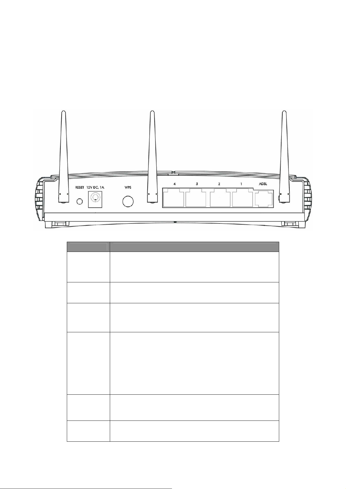
Chapter 2 Physical Description
2.1 Back Panel
Parameter Description
The antenna connector of the router is reverse SMA
Antenna
Connector
Reset
Power
Jack
WPS
connector. It allows you to connecting an external
antenna with reverse SMA connector to the router
easily.
Press and hold <Reset> button for 5 seconds to
clear all settings.
Please plug the power adapter attached with the
ADSL Router to the power jack. The power adapter
is 12VDC, 1A.
Wi-Fi Protected Setup (WPS) is the simplest way to
build connection between wireless network clients
and this ADSL router. Press this button on the router
and enable WPS function of the wireless clients, the
router and clients will automatically configure the
security key and connect directly. Please note that
the router will wait for WPS requests from wireless
clients in 2 minutes after the WPS button is pressed.
The Broadband router’s 4 LAN ports are where
LAN
ADSL
users can connect LAN’s PCs, printer servers, hubs
and switches etc.
Connect the supplied RJ-11 telephone line to this
port and your ADSL/telephone network.
6
Page 10
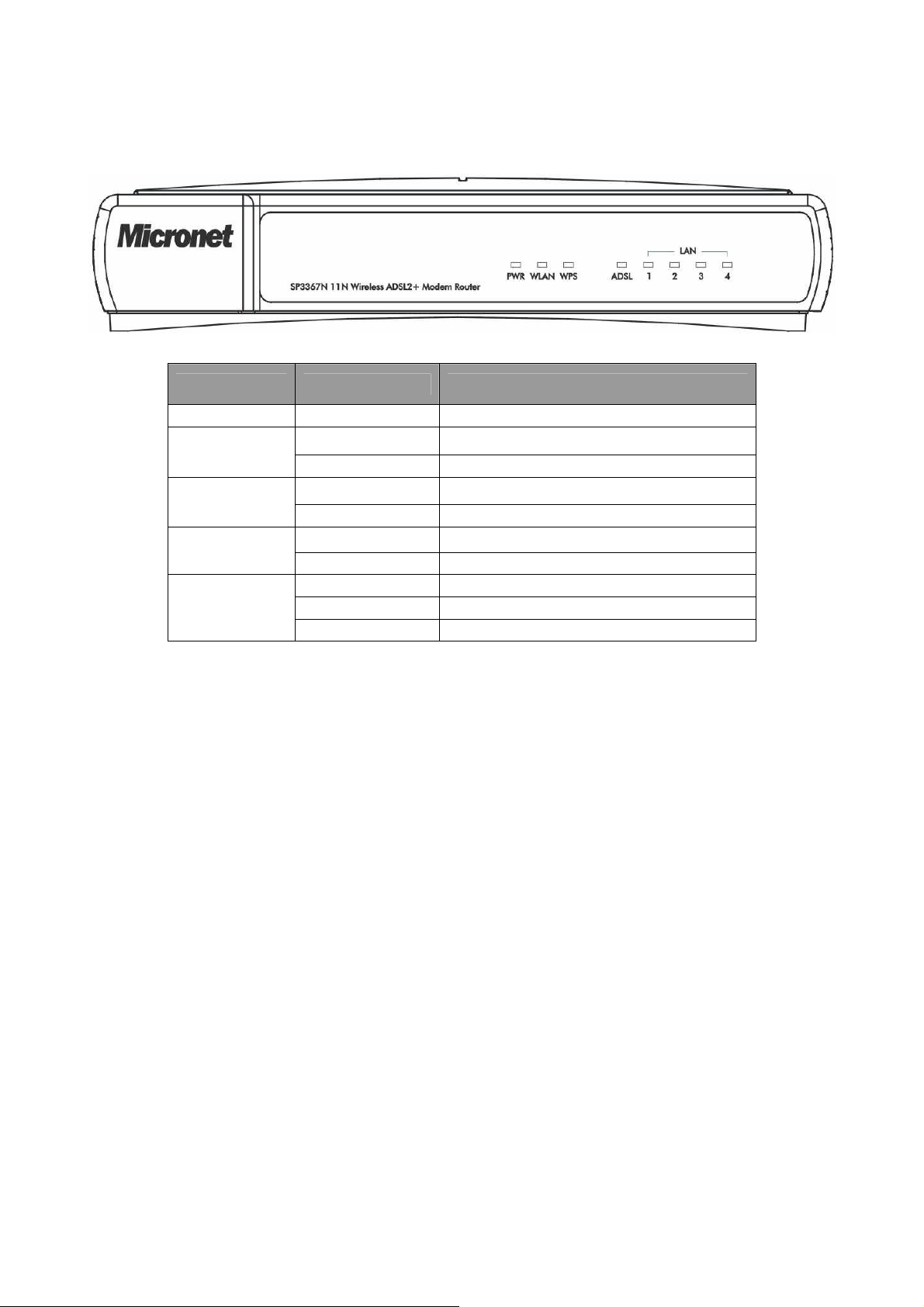
2.2 Front Panel
LED Status Description
PWR
WLAN
WPS
ADSL
LAN
(1-4)
On Device is switched on.
Off Wireless LAN disabled.
Blinking Wireless transmission detected.
Off WPS function is disabled.
Blinking WPS function is enabled.
On Successful connection to DSLAM.
Blinking No connection.
On LAN port is connected.
Off No network connection.
Blinking Data is being sent or received.
7
Page 11
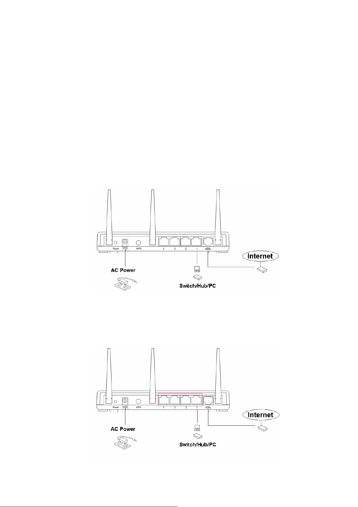
Chapter 3 System and Network Setup
3.1 Build Network Connection
Please follow the following instruction to build the network connection between the new
wireless router and other network computers and devices:
1. Connect the ADSL port of modem router by telephone cable (RJ-11) to an outlet
or splitter.
2. Connect all computers, network devices (network-enabled consumer devices
other than computers, like game console, or switch / hub) to the LAN port of the
router.
8
Page 12
3. Connect the A/C power adapter to the wall socket, and then connect it to the
‘Power’ socket of the router.
4. The ADSL LED will be ON if the router is connected to the ADSL cable and
receives the ADSL signals successfully. If the LED is blinking, please contact with
your ISP (Internet Service Provider) to check the problem.
3.2 Connecting to Web-Based Management
After the network connection is established, the next step is to setup the router with
proper network parameters for the user’s network environment.
Before connecting to the router and start configuration procedures, user’s computer
must be able to get an IP address automatically (use dynamic IP address). If the PC is
set to ‘static IP address’, then follow instructions below to reconfigure it to ‘dynamic IP
address’.
a) Windows 95/98/Me
1. Click the Start button and select <Settings>, then click <Control Panel>. The
Control Panel window will appear.
2. Double-click on <Network> icon. The Network window will appear.
3.2.1 IP Address Configuration
9
Page 13
3. Check the list of Network Components. If TCP/IP is not installed, click the
<Add> button to install it. If TCP/IP is installed, go to step 6.
4. In the Network Component Type dialog box, select <Protocol> and click <Add>
button.
5. In the Select Network Protocol dialog box, select <Microsoft> and <TCP/IP>
then click the <OK> button to start installing the TCP/IP protocol. Windows CD
may be needed to complete the installation.
6. After installing TCP/IP, go back to the Network dialog box. Select <TCP/IP>
from the list of Network Components and then click the <Properties> button.
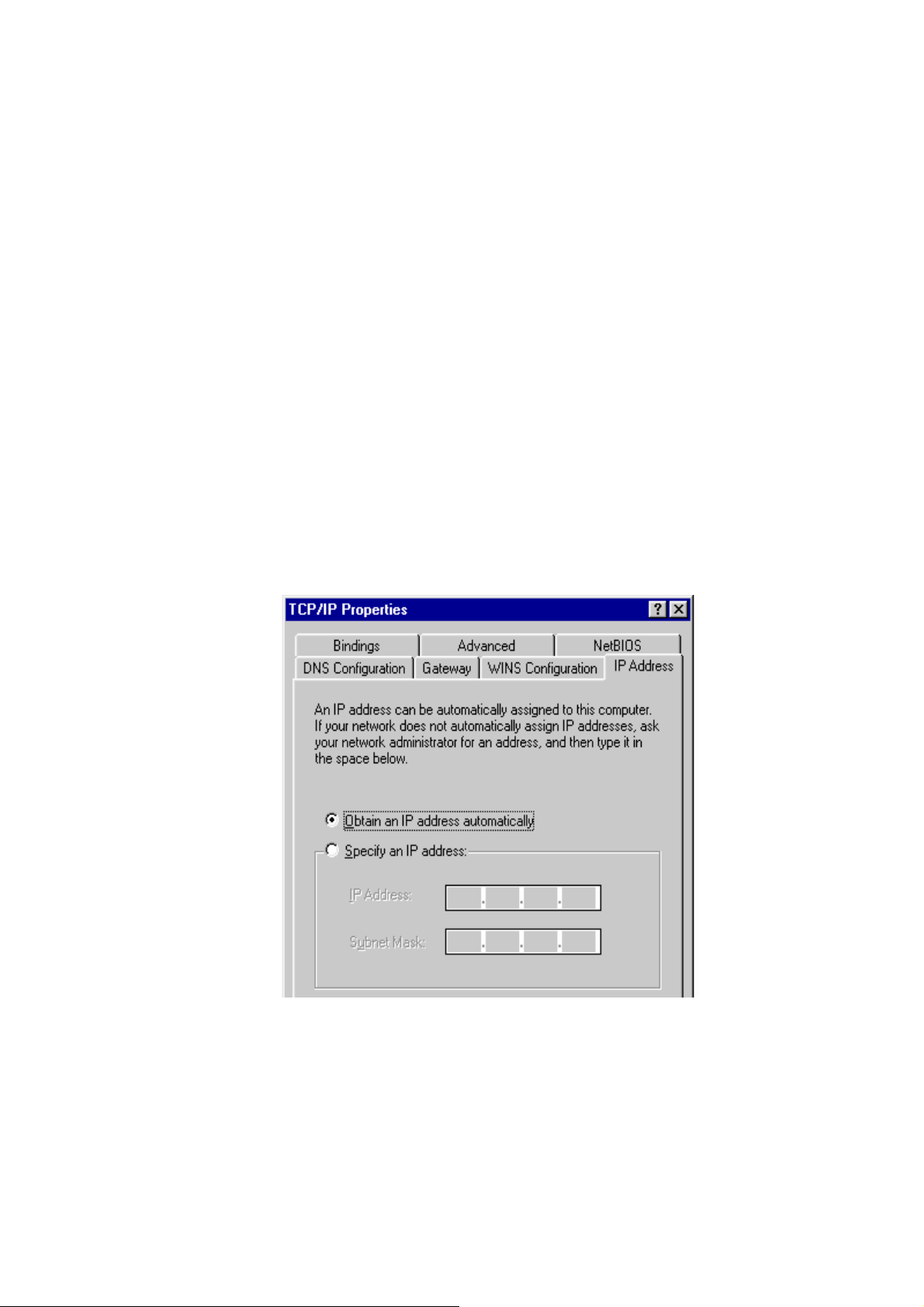
7. Check each of the tabs and verify the following settings:
y Bindings: Check Client for Microsoft Networks and File and printer sharing
for Microsoft Networks.
y Gateway: All fields are blank.
y DNS Configuration: Select Disable DNS.
y WINS Configuration: Select Disable WINS Resolution.
y IP Address: Select Obtain IP address automatically.
8. Reboot the PC. PC will now obtain an IP address automatically from the
Broadband Router’s DHCP server.
9. Please make sure that the Broadband router’s DHCP server is the only DHCP
server available on the LAN network.
10. Proceed to Web-based User Interface once IP address is correctly configured.
10
Page 14
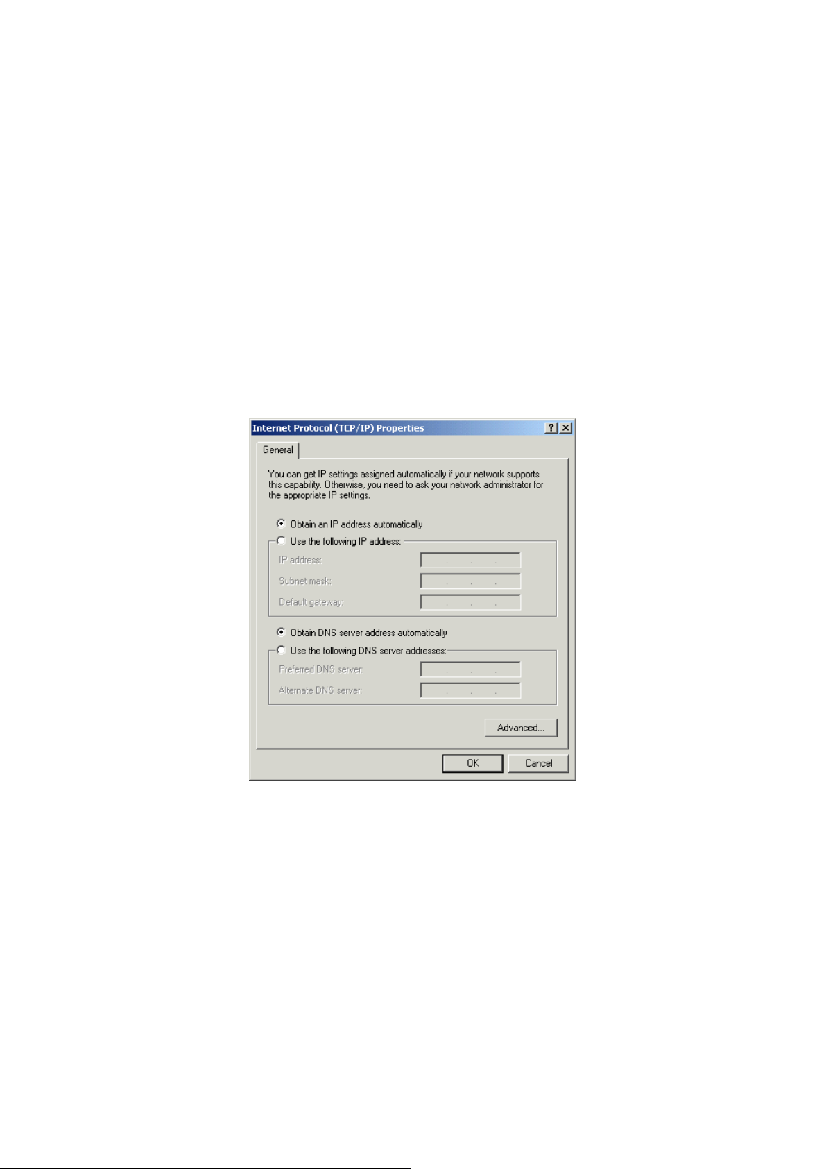
b) Windows 2000
1. Click the <Start> button and select <Settings>, then click <Control Panel>.
The Control Panel window will appear.
2. Double-click <Network and Dial-up Connections> icon. In the Network and
Dial-up Connection window, double-click on <Local Area Connection> icon.
The Local Area Connection window will appear.
3. In the Local Area Connection window, click the <Properties> button.
4. Check the list of Network Components. Users should see Internet Protocol
[TCP/IP] on the list. Select it and click the <Properties> button.
5. In the Internet Protocol (TCP/IP) Properties window, select <Obtain an IP
address automatically> and <Obtain DNS server address automatically> as
shown on the following screen.
6. Click <OK> to confirm the setting. The PC will now obtain an IP address
automatically from the Broadband Router’s DHCP server.
7. Please make sure that the Broadband router’s DHCP server is the only DHCP
server available on the LAN network.
8. Proceed to Web-based User Interface once IP address is correctly configured.
c) Windows XP
1. Click the <Start> button and select <Settings>, then click <Network
Connections>. The Network connections window will appear.
11
Page 15
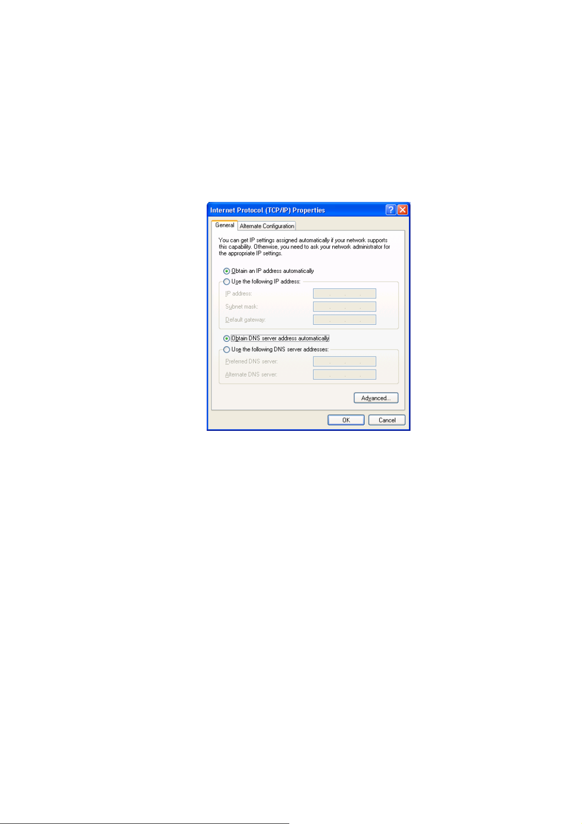
2. Double-click <Local Area Connection> icon. The Local Area Connection
window will appear.
3. Check the list of Network Components. Users should see Internet Protocol
[TCP/IP] on the list. Select it and click the <Properties> button.
4. In the Internet Protocol (TCP/IP) Properties window, select <Obtain an IP
address automatically> and <Obtain DNS server address automatically> as
shown on the following screen.
5. Click <OK> to confirm the setting. PC will now obtain an IP address
automatically from the Broadband Router’s DHCP server.
6. Please make sure that the Broadband router’s DHCP server is the only DHCP
server available on the LAN network.
d) Windows Vista
1. Click <Start> button, then click control panel. Click <View Network Status and
Tasks>, then click <Manage Network Connections>. Right-click <Local Area
Network>, then select <Properties>. Local Area Connection Properties window
will appear, select <Internet Protocol Version 4 (TCP / IPv4)> and click
<Properties>.
12
Page 16
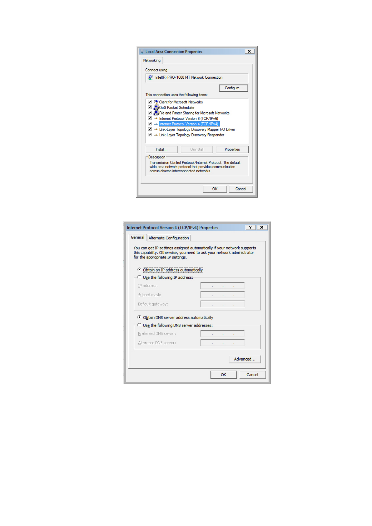
2. Select <Obtain an IP address automaticall y> and <Obtain DNS server
address automatically>, then click <OK>.
13
Page 17
3.2.2 Router’s IP Address
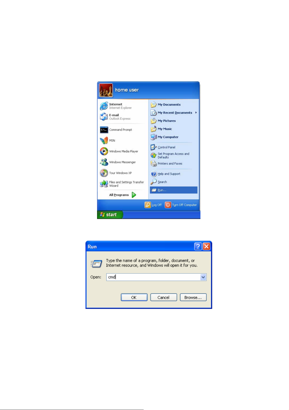
1. After the IP address setup is complete, please click <Start> then <Run> at the
bottom lower corner of the desktop.
2. Enter ‘cmd’ command and click <OK>.
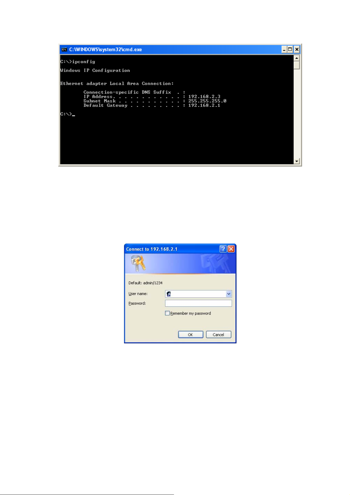
3. Input ‘ipconfig’, then press ‘Enter’ key. Please check the IP address followed by
‘Default Gateway’ (In this example, the IP address of router is 192.168.2.1, please
note that this value may be different).
14
Page 18
3.2.3 Starting Web-Based Management UI
1. After the computer has obtained an IP address from router, please start the web
browser. Input the IP address of router in the address bar and the following
message should appear:
2. Please input username and password in the field respectively. Default username is
‘admin’ and default password is ‘1234’, then press <OK> button. Once the login
details are entered correctly, users can see the web management interface of this
router.
15
Page 19

16
Page 20

Chapter 4 Web-Based Management UI
4.1 Quick Start Wizard
The Quick Start section is designed to get the broadband router running as quickly as
possible. In the Quick Start, users are required to fill in only the information necessary
to access the Internet. Once user clicks on the <Quick Start> and click on <Run
Wizard>, the following screen will appear.
Step1: Set User Password
Please enter the new password and confirm the password again.
17
Page 21

Step 2: Time Zone
The Time Zone allows router to base its time on the settings configured in this section.
Click on <NEXT> to proceed to the next page: Broadband Type.
18
Page 22

Step 3: Broadband Type
In this section users have to select one of four types of connections that it will be using
to connect to broadband router WAN port to the ISP (see screen below). Different ISPs
require different methods of connecting to the Internet, please check with the ISP as to
the type of connection it requires.
Parameter Description
Dynamic IP Address ISP will automatically provide an IP address.
Static IP Address ISP has given users an IP address already.
PPPoE/PPPoA
Bridge Mode
Click on one of the WAN type and then proceed to the manual’s relevant sub-section.
Click on <Back> to return to the previous screen.
PPPoE (PPP over Ethernet) and PPPoA (PPP over ATM) are
common connection methods used for xDSL.
Device will act as modem only equipment to prevent conflict
with other routers.
19
Page 23

Step 4 Enter the Internet account details provided by ISP
Click <Next> to complete the Quick Start Wizard and restart modem router.
4.2 Interface Setup
4.2.1 Internet
Below interface is for entering all parameters in regards to connecting to ISP devices
for Internet. Please consult below tables for detail description of each parameter.
20
Page 24

ATM VC
Parameter Description
Virtual Circuit
VPI
VCI
VPI (Virtual Path Identifier) and VCI (Virtual Channel Identifier
define a virtual circuit.
VPI is a virtual path determines the way an ATM cell should
be routed. The VPI is an 8-bit (in UNI) or 12-bit (in NNI)
number that is included in the header of an ATM cell. The
valid range for the VPI is 0 to 255. Enter the VPI assigned by
the ISP.
VCI is the label given to an ATM VC to identify it and
determine its destination. The VCI is a 16-bit number that is
included in the header of an ATM cell. The valid range for the
VCI is 32 to 65535. Enter the VCI assigned by the ISP.
21
Page 25

CBR (Constant Bit Rate) – This class i s used for em ulating
circuit switching. The cell rate is constant with time. Select
CBR to specify fixed (always on) bandwidth for voice or data
traffic.
UBR (Unspecified Bit Rate) – Select UBR for applications
that are non-time sensitive, such as e-mail.
rtVBR (real time Variable Bit Rate) – This class is similar to
ATM QoS
PCR
SCR
MBS
nrtVBR but is designed for applications that are sensitive to
cell-delay variation. Examples for real-time VBR are voice
with speech activity detection (SAD) and interactive
compressed video.
nrtVBR (non-real time Variable Bit Rate) – This class
allows users to send traffic at a rate that varies with time
depending on the availability of user information. Statistical
multiplexing is provided to make optimum use of network
resources. Multimedia e-mail is an example of nrtVBR.
Divide the DSL line rate (bps) by 424 (the size of an ATM cell)
to find the PCR (Peak Cell Rate). This is the maximum rate at
which the sender can send cells.
SCR (Sustain Cell Rate) is the average rate, as measured
over a long interval, in the order of the connection lifetime.
MBS (Maximum Burst Size) refers to the maximum number of
cells that can be sent at the peak rate. Type the MBS, which
is less than 65535.
Encapsulation
The router can be connected to your service provider in any of the following ways.
Parameter Description
Dynamic IP Address ISP will automatically provide an IP address.
Static IP Address ISP has given users an IP address already.
PPPoE/PPPoA
Bridge Mode
Dynamic IP Address/Static IP Address/PPPoE/PPPoA/Bridge Mode
After you have selected the ISP Type, this web page will be varied depending on the
ISP Type you select. Please refer to the following table for the explanation of each
PPPoE (PPP over Ethernet) and PPPoA (PPP over ATM) are
common connection methods used for xDSL.
Device will act as modem only equipment to prevent conflict
with other routers.
parameter.
22
Page 26

Parameter Description
Service Name Enter the name of your ISP.
User Name Enter the username exactly as your ISP assigned.
Password Enter the password that your ISP has assigned to you.
Please check with your ISP the method of multiplexing. In
Bridge Mode, please select “1483 Bridge IP LLC” or “1483
Encapsulation
Bridge Interface
Connection
TCP MSS Option
Get IP Address
Bridge IP VC-Mux”. In PPPoE/PPPoA mode, please select
“PPPoE LLC”, “PPPoE VC-Mux”, “PPPoA LLC”, or “PPPoA
VC-Mux”.
This router has built-in ADSL modem and is able to connect
to ISP directly. Alternatively, if you want to use the dial up
software to manually connect to the ISP, you have to activate
the”Bridge Interface”.
Always On – The connection will be kept always on. If the
connection is interrupted, the router will re-connect
automatically.
Connect On-Demand – Only connect when you want to surf
the Internet. “Close if idle for xx minutes” is set to stop the
connection when the network traffic is not sending or
receiving after an idle time.
Connect Manually – After you have selected this option,
please go to Status page. You will see the “Connect” button,
click it and the router will connect to the ISP. If you want to
stop the connection, please click “Disconnect” button.
The “TCP MSS Option” enables the configuration of the
maximum segment size (MSS) for transient packets that
traverse a router, specifically TCP segments in the SYN bit
set, when PPPoE is being used in the network. Please specify
the MSS range from 100 to 1452 bytes or 0 byte as the
default value.
Choose Static or Dynamic IP Address. If Static IP is selected,
please set the IP Address, Subnet Mask and Gateway
obtained from your ISP.
Static IP Address Enter the IP Address assigned by your ISP.
IP Subnet Mask Enter the Subnet Mask assigned by your ISP.
Gateway Enter the Gateway assigned by your ISP.
NAT (Network Address Translation), an Internet standard that
enables a
NAT
Default Route
TCP MTU Option
addresses
for external traffic. When NAT is enabled, the router will help
to make all necessary IP address translations for the PC
connected to the router to access the Internet.
When “Default Router” is enabled, all the packets for
destinations not known by the router's
to the default route. By default, it is enabled.
MTU (Maximum Transmission Unit) determine the maximum
size of each packet in any transmission within the network.
Please specify the MTU range from 100 to 1500 bytes or 0
byte as the default value.
local-area network (LAN) to use one set of IP
for internal traffic and a second set of addresses
routing table are sent
23
Page 27

Dynamic routing allows routing tables in routers to change as
the possible routes change. This router supports RIP1, RIP2-
Dynamic Route
Multicast
MAC Spoofing
B and RIP2-M protocols for dynamic routing. After the RIP
protocol is selected, please choose the RIP direction from
“None”, “Both”, “IN Only” or “OUT Only”.
Specify the method of transmitting data simultaneously to
many receivers. Please select “IGMP v1” or “IGMP v2” as the
multicast protocol or select “Disabled” to disable the function.
Once your ISP service requires identifying the MAC address
of the devices. You can enable MAC Spoofing function and
enter the valid MAC address, it allows you to change the MAC
address of the router in order to access to the Internet
service.
4.2.2 LAN
Router Local IP
IP Address
IP Subnet Mask
Parameter Description
Enter the IP Address of the ADSL router for the local user to
access the router’s web page. By default, the IP Address is
192.168.2.1.
Enter the Subnet Mask of the ADSL router. By default, the
Subnet Mask is 255.255.255.0.
24
Page 28

Dynamic Route
Multicast
IGMP Snoop
DHCP
Parameter Description
DHCP
Starting IP Address
IP Pool Count
Lease Time
DNS Relay
Primary DNS Server
Secondary DNS
Server
Dynamic routing allows routing tables in routers to change as
the possible routes change. This router supports RIP1, RIP2B and RIP2-M protocols for dynamic routing. After the RIP
protocol is selected, please choose the RIP direction from
“None”, “Both”, “IN Only” or “OUT Only”.
Specify the method of transmitting data simultaneously to
many receivers. Please select “IGMP v1” or “IGMP v2” as the
multicast protocol or select “Disabled” to disable the function.
When “IGMP Snoop” (Internet Group Management Protocol
Snoop) is enabled, the router can make intelligent multicast
forwarding decisions by examining the contents of each
frame’s IP header. Without the function, the router will
broadcast the multicast packets to each port and may create
excessive traffic on the network and degrade the performance
of the network.
Users can enable or disable the DHCP server. By enabling
the DHCP server the router will automatically give LAN clients
an IP address. If the DHCP is not enabled then you’ll have to
manually set your LAN client’s IP addresses.
If the DHCP Server is enabled, please set the “Starting IP
Address” which will be the first IP Address assigned to the
LAN client. By default, the “Starting IP Address” is
192.168.2.100.
Users can select a particular IP address range for your DHCP
server to issue IP addresses to your LAN Clients.
By default, the “IP Pool Count” is 100. The IP range is starting
from IP 192.168.2.100 to 192.168.2.199.
In the Lease Time setting you can specify the time period that
the DHCP Server lends an IP address to your LAN clients.
The DHCP will change the LAN client’s IP address when this
time threshold period is terminated.
A Domain Name System (DNS) server is like an index of IP
addresses and Web addresses. If users type a Web address
into your browser, such as “www.router.com”, a DNS server
will find that name in its index and the matching IP address.
Please select “Use Auto Discovered DNS Server Onl y ” to
auto set the DNS Server. If there is a DNS server that you
would rather use, please select “Use Discovered DNS Server
Only” and you need to specify the IP address of that DNS
server.
Enter the ISP’s DNS Server IP Address; or user can specify
preferred DNS Server IP Address.
This is optional. Users can enter another DNS Server’s IP
Address as a backup. The secondary DNS will be used if the
Primary DNS fail.
25
Page 29

4.2.3 Wireless
Access Point Settings
Parameter Description
Access Point
Channel
Beacon Interval
RTS/CTS Threshold
Fragmentation
Threshold
Activated or deactivated the wireless function of the router.
When it is activated, the router will be an access point for
other wireless clients to connect wirelessly.
It is the radio channel used by the wireless LAN. All devices in
the same wireless LAN should use the same channel. Please
select the country you are located and designate a channel
that the router will use. For product available in the
USA/Canada market, only channel 1~11 can be operated. For
product in Europe market, only channel 1~13 can be
selected. Selection of other channels is not permitted. If you
want to let the router automatically find an available channel
with the highest signal strength, please select “Auto”. The
auto-selective channel will be shown in the “Current Channel”
field.
The interval of time that this wireless router broadcast a
beacon. Beacon is used to synchronize the wireless network.
The range for the beacon period is between 20 and 1000 with
a typical value of 100 (milliseconds).
When the packet size is smaller than the RTS threshold, the
wireless router will not use the RTS/CTS mechanism to send
this packet. The range is from 1500 to 2347.
Fragment Threshold specifies the maximum size of packet
during the fragmentation of data to be transmitted. If you set
this value too low, it will result in bad performance. Enter a
value from 256 to 2346.
26
Page 30

Determines the interval the Access Point will send its
DTIM
Wireless Mode
broadcast traffic. The range is from 1 to 255 and the default
value is 3 beacons.
802.11b – It only allows 802.11b wireless network client to
connect to this router (maximum transfer rate 11Mbps).
802.11g – It only allows 802.11g wireless network client to
connect to this router (maximum transfer rate 54Mbps).
802.11b+g – It only allows 802.11b and 802.11g wireless
network client to connect to this router (maximum transfer rate
11Mbps for 802.11b clients, and maximum 54Mbps for
802.11g clients).
802.11n – It only allows 802.11n wireless network client to
connect to this router (maximum transfer rate 300Mbps).
802.11g+n – It allows 802.11g, and 802.11n wireless network
client to connect to this router (maximum transfer rate
54Mbps for 802.11g clients, and maximum 300Mbps for
802.11n clients).
802.11b+g+n – It allows 802.11b, 802.11g, and 802.11n
wireless network client to connect to this router (maximum
transfer rate 11Mbps for 802.11b clients, maximum 54Mbps
for 802.11g clients, and maximum 300Mbps for 802.11n
clients).
NOTE: For 802.11b and 802.11g mode, the signals can be
transmitted only by antenna 1 (The antenna in the right side
of the rear panel).
For 802.11n mode, the router is operating in a 2T3R Spatial
Multiplexing MIMO configuration. 2 antennas are for signal
transmitting and 3 antennas are for signal receiving.
11n Settings
Channel Bandwidth
Extension Channel
Guard Interval
MCS
SSID Index
Parameter Description
Set channel width of wireless radio. Do not modify default
value if you don’t know what it is, default setting is ‘20/40
MHz’.
Select the extension channel to above or below the control
channel while 40MHz channel bandwidth is selected. Do not
modify the default value if you don’t know what it is.
It is one of several draft-n features designed to improve
efficiency. Select 400nsec to provide a shorter delay between
transmission frames in 11n network. The throughput in
400nec guard interval is better than 800nsec guard interval.
Select MCS 0-15 to configure the data rate of 11n network.
When MCS 15 is selected, the data rate is up to 300Mbps. It
is recommended to set “Auto” and the router will negotiate
with wireless clients to operate in a proper data rate.
This router can support multiple SSIDs. By default, this
function is disabled.
27
Page 31

Select “Yes” to make the SSID to be visible so wireless clients
Broadcast SSID
WMM
Use WPS
can scan the router within the network. Select “No” if you want
to hide the SSID of the router. Wireless clients have to set the
same SSID of the router in order to access the network.
The short of Wi-Fi Multi Media, it will enhance the data
transfer performance of multimedia contents when they’re
being transferred over wireless network.
Select “Yes” to enable WPS function, Select “No” to disable
WPS.
WPS Settings
Wi-Fi Protected Setup (WPS) is the simplest way to build connection between wireless
network clients and this router. Users do not have to select encryption mode and input
a long encryption passphrase every time, they only have to press a button on wireless
client and this wireless router to allow WPS complete the setup.
This router supports two types of WPS: Push-Button Configuration (PBC), and PIN
code. If users want to use PBC, they have to switch this wireless router to WPS mode
and push a specific button on the wireless client to start WPS mode. Users can push
Reset/WPS button of this router, or select “PBC” and click “Start WPS” button in the
WPS setup page. If users want to use PIN code, they have to know the PIN code of
wireless client and switch it to WPS mode, then set the PIN code of the wireless client
to this router in the WPS setup page and click “Start WPS” button.
Parameter Description
Enter the PIN code of the wireless client here. If you have
Enrollee PIN Code
entered the PIN code of the wireless client and switch to the
WPS mode, the security settings of the wireless client will be
set to the same as the router.
WPS progress Display the progress during WPS communication.
Reset to OOB
SSID
Click this button and all the wireless settings of the router will
be reset to factory defaults.
The SSID (up to 32 printable ASCII characters) is the unique
name identified in a WLAN. The ID prevents the unintentional
merging of two co-located WLANs. The default SSID of the
router is “default”.
28
Page 32

It’s very important to set wireless security settings properly. If
not enabled, hackers and malicious users can reach your
network and valuable data without user’s consent and this will
cause serious security problem.
Authentication Type
This router supports WEP, WPA-PSK and WPA2-PSK
authentication type. If the router has enabled the
authentication, all the wireless clients’ settings have to be
consistent with the router for building the connection.
WEP/WPA-PSK/WPA2-PSK & WPA-PSK/WPA2-PSK
Parameter Description
WEP is less level of security than WPA. WEP supports 64-bit
and 128-bit key lengths to encrypt the wireless data. The
WEP-64Bits
WEP-128Bits
WPA-PSK
WPA2-PSK
WPA-PSK/ WPA2-PSK
longer key length will provide higher security. When “WEP64Bits” is selected, you have to enter exactly 5 ASCII
characters (“a-z” and “0-9”) or 10 hexadecimal digits ("0-9",
"a-f") for each Key (1-4).
When “WEP-128Bits” is selected, you have to enter exactly
13 ASCII characters (“a-z” and “0-9”) or 26 hexadecimal digits
("0-9", "a-f") for each Key (1-4).
WPA-PSK is suitable for home and small business. It uses
TKIP or AES for data encryption. When “WPA-PSK” is
selected, please select the encryption method and enter 8-63
ASCII characters or 64 hexadecimal characters as the “PreShared Key”.
WPA2-PSK is also for home and small business. It uses TKIP
or AES for data encryption. WPA2-PSK offers the highest
level of security available. When “WPA2-PSK” is selected,
please select the encryption method and enter 8-63 ASCII
characters or 64 hexadecimal characters as the “Pre-Shared
Key”.
When “WPA-PSK/WPA2-PSK” is selected, please select the
encryption method (TKIP or AES) and enter 8-63 ASCII
characters or 64 hexadecimal characters as the “Pre-Shared
Key”.
29
Page 33

Wireless MAC Address Filter
Parameter Description
Active
Action
Mac Address #1-8
This router can prevent the wireless clients from accessing
the wireless network by checking the MAC Address of the
clients. If users enable this function, please set the MAC
Address of the wireless clients to be filtered.
Allow Association – Only allow the wireless clients with the
MAC Address specified to access the router.
Deny Association – The wireless clients with the MAC
Address specified will be denied accessing to the router.
Please enter the MAC Address of the wireless clients for the
filtering control.
30
Page 34

4.3 Advanced Setup
4.3.1 Firewall
Parameter Description
Firewall
SPI
When you enable the firewall function, it will protect you from
following attacks of WAN side:
¾ SYN flooding attack
¾ Ping of Death
¾ Teardrop
¾ Land attack
If you enable SPI, all traffics initiated from WAN site will be
blocked including DMZ, Virtual Server, etc.
4.3.2 Routing
31
Page 35

Routing Table List
Users can see the current routing table of the router here. If they want to add another
routing rule, please click “ADD ROUTE”.
Parameter Description
Dest IP Show the IP Address of the destination LAN.
Show the Subnet Mask of the destination LAN. If it shows “8”
Mask
Gateway IP
Metric
Device
that means the Subnet Mask is “255.0.0.0”; “16” means the
Subnet Mask is “255.255.0.0”; “24” means the Subnet Mask is
“255.255.255.0”.
The next stop gateway of the path toward the destination
LAN. This is the IP of the neighbor router that this router
should communicate with on the path to the destination LAN.
The number of hops (routers) to pass through to reach the
destination LAN. It must be between 1 and 15.
Show the interface that go to the next hop (router), such as
LAN port.
Use The counter for access time.
Edit Edit the route, this icon is not shown for system default route.
Drop Drop the route, this icon is not shown for system default route.
Add Route
If users have another router with a LAN-to-LAN connection, they may need to create a
static routing on the router that is the gateway to Internet.
Parameter Description
Destination IP
Address
Enter the IP Address of the destination LAN.
32
Page 36

IP Subnet Mask Enter the Subnet Mask address of the destination LAN.
This is the gateway IP Address where packets are sent. Enter
Gateway IP Address
Metric
Announced in RIP
the gateway IP Address and select the channel (PVC) you
want to configure.
The number of hops (routers) to pass through to reach the
destination LAN. It must be between 1 and 15.
Select “Yes”, this routing path will be propagated to other
hosts through RIP broadcasts. Select “No”, this routing path
will be kept private and it is not included in RIP broadcasts.
4.3.3 NAT
Network Address Translation (NAT) allows multiple users at your local site to access
the Internet through a single Public IP Address or multiple Public IP Addresses. NAT
provides Firewall protection from hacker attacks and has the flexibility to allow you to
map Private IP Addresses to Public IP Addresses for key services such as Websites
and FTP.
Parameter Description
Virtual Circuit Please select the channel (PVC) you want to configure.
NAT Status
Number of IPs
The activated or deactivated status for the NAT function will
be shown here.
Select “Single” if you only have a public IP Address. Select
“Multiple” if you have multiple IP Addresses.
33
Page 37

DMZ
The DMZ Host is a local computer exposed to the Internet. When setting a particular
internal IP Address as the DMZ Host, all incoming packets will be checked by the
firewall and NAT algorithms then passed to the DMZ Host.
For example, if you have a local client PC that cannot run an Internet application (e.g.
Games) properly from behind the NAT firewall, then you can open the client up to
unrestricted two-way Internet access by defining a DMZ Host.
Parameter Description
DMZ setting for Show the DMZ setting is for single or multiple IP Addresses.
DMZ Enable or disable the DMZ function.
DMZ Host IP Address
Enter a static IP Address to the DMZ Host. This IP Address
will be exposed to the Internet.
Virtual Server
Use the Virtual Server function when you want different servers/clients in your LAN to
handle different service/Internet application type (e.g. Email, FTP, Web server etc.)
from the Internet. Computers use numbers called port numbers to recognize a
particular service/Internet application type. The Virtual Server allows you to re-direct a
particular service port number (from the Internet/WAN) to a particular LAN’s private IP
Address and its service port number.
34
Page 38

Parameter Description
Virtual Server for
Show the Virtual Server setting is for single or multiple IP
Addresses.
Rule Index Choose the rule number.
Select the application of the virtual server, for example: FTP
Application
or HTTP Server. When the application is selected, the port
number for the application will be assigned automatically.
Start Port Number Enter the start port number.
End Port Number Enter the end port number.
It is recommended to enter a static IP Address for the server
here. If the server’s IP Address is obtained from DHCP
Server, the IP Address may be changed dynamically and will
Local IP Address
cause problem in the feature. Please assign a static IP
Address to the server and make sure that the IP Address is
not in the range of IP Addresses that the DHCP Server will
assign.
35
Page 39

4.3.4 ADSL
Parameter Description
The default setting is “Auto Sync-Up”. This mode will
ADSL Mode
ADSL Type
automatically detect the ADSL mode including ADSL2+,
ADSL2, G.DMT, T1.413 and G.lite. If you are not sure how to
select the ADSL mode, please contact with your ISP.
Check with your ISP about the ADSL type of the DSLAM
device they use.
36
Page 40

4.4 Access Management
4.4.1 ACL
If users want to restrict users from accessing certain Internet applications/services such
as Internet websites, email, FTP etc., then this is the place to set that configuration.
Access Control allows users to define the traffic type permitted in your LAN or WAN.
Users can control which computer can have access to these services by entering the
IP Address of the computer.
Parameter Description
Activate or deactivate the Access Control function. When you
ACL
have activated the function, please make sure that you have
designated the available applications/services or you will be
denied to access all the services.
ACL Rule Index This is the item number to record the setting rule.
The default 0.0.0.0~0.0.0.0 allows any user to use this service
Secure IP Address
Application
Interface
to remotely manage the router. Type a range of IP Addresses
to authorize access to a number of users with matching IP
Addresses.
Choose the services that you permit to use in your LAN or
WAN interface. These services include Web, FTP, Telnet,
SNMP and Ping.
Select the interface that the user is allowed to use services
through it. It includes LAN, WAN or Both.
37
Page 41

4.4.2 Filter
Users can forbid some users from accessing the router by filtering IP Address or MAC
Address. Users can also restrict some applications or URLs be accessing by users
through the router here. Please select the filter type to start configuring.
IP/ MAC Filter
IP/ MAC Filter Set Editing
38
Page 42

Parameter Description
IP/MAC Filter Set
Index
Interface Select which channel (PVC) to configure.
Direction
IP / MAC Filter Rule Editing
Parameter Description
IP/MAC Filter Rule
Index
Rule Type Select to filter through the IP Address or MAC Address.
Active
Source IP Address
Subnet Mask Enter the Subnet Mask based on the Source IP Address.
Port Number
Destination IP
Address
Subnet Mask Enter the Subnet Mask based on the Destination IP Address.
This is the item number to record the setting.
Select the access to the Internet (Outgoing) or from the
Internet (Incoming), or Both.
This is the item number to record the setting rule.
Select “Yes” to enable the current rule, select “No” to cancel
the current rule.
Enter the start IP Address which will be monitored. If “0.0.0.0”
is set, it means for any IP Address.
LAN users use port number to distinguish one network
application over another such as 21 is for FTP service. The
port number range is from 0 to 65535. It is recommended that
this option be configured by an advanced user.
Enter the start IP Address which will be monitored. If “0.0.0.0”
is set, it means for any IP Address.
Port Number This is the port or port ranges that define the application.
Protocol
Rule Unmatched
Application Filter
It is the packet protocol type used by the application. Please
select “TCP”, “UDP” or “ICMP”. For example, FTP service,
you have to select “TCP”.
Select action for the traffic mismatching current rule.
“Forward” is to leave it pass through. “Next” is to check it by
the next rule.
39
Page 43

Parameter Description
Application Filter Activate or deactivate the application filter.
ICQ/MSN/YMSG/ Real
Audio/Video
If “Allow” is selected, the packets for these applications will be
able to pass through the router. If you want to restrict these
applications, please select “Deny”.
URL Filter
Parameter Description
Active Activate or deactivate the URL filter.
URL Index This is the item number to record the setting.
40
Page 44

A URL can be thought of as the "address" of a web page and
URL
is sometimes referred to informally as a "web address."
Please enter the web address here that you want to restrict to
be connected.
4.4.3 SNMP
Simple Network Management Protocol (SNMP) is a popular protocol for network
management. It is used for collecting information and configuring the network devices.
This router supports SNMP agent function, which allows a manager station to manage
and monitor the router through the network.
Parameter Description
Get Community
Enter the password for the incoming Get- and Get Next
requests from the management station.
Set Community Enter the password for a Set request to configure the router.
4.4.4 UPnP
When the UPnP function is enabled, the router can be detected by UPnP compliant
system such as Windows XP. The router will be displayed in the Neighborhood of
Windows XP, so you can directly double click the router or right click the router and
select “Invoke” to configure the router through web browser.
41
Page 45

Parameter Description
UPnP Activated or deactivated the UPnP function.
Select this check box to allow UPnP-enabled applications to
automatically configure the router so that they can
communicate through the router, for example by using NAT
Auto-configured
traversal, UPnP applications automatically reserve a NAT
forwarding port in order to communicate with another UPnP
enabled device. This eliminates the need to manually
configure port forwarding for the UPnP enabled application.
4.4.5 DDNS
DDNS allows you to map the static domain name to a dynamic IP address. You must
get an account, password and your static domain name from the DDNS service
providers.
42
Page 46

Parameter Description
Dynamic DNS Activated or deactivated the DDNS function.
Service Provider This router supports DynDNS service provider.
My Host Name
Enter the domain name assigned to your router by the service
provider.
E-mail Address Enter the E-mail address assigned by DDNS service provider.
Username Enter your username.
Password Enter the password you set for the DDNS service.
Wildcard Support Enable or disable the wildcard to stand for some characters.
43
Page 47

4.5 Maintenance
4.5.1 Administrator
Parameter Description
Username The username of the router is “admin” by default.
New Password Enter up to 30-digit for the new password.
Confirm Password Enter the new password again to confirm the setting.
4.5.2 Time Zone
The Time Zone allows the router to set its time and this will affect function such as
System Log.
44
Page 48

Parameter Description
Current Date/Time Show the current date/time of the router.
NTP Server Automatically – Set the time automatically with
Synchronize time with
Time Zone
a NTP Server.
PC’s Clock – Set the time synchronize with computer.
Manually – Set the time manually.
Select the time zone of the country you are currently in. The
router will set its time based on your selection.
Daylight Saving Select this option if it is in daylight saving time.
NTP Server Address Enter the IP Address of your time server.
4.5.3 Firmware
If users have new firmware for some features update, please upgrade firmware of the
router in this section.
Parameter Description
Current Firmware
Version
New Firmware
Location
New Romfile Location
Romfile Backup
Upgrade
The current firmware version will be shown here.
Type in the location of the new firmware or click “Browse” to
find it.
To restore the backup settings, please type in the location of
the backup file or click “Browse” to locate.
To save the current settings as a backup file, please click
“ROMFILE SAVE”. Then please change the file name and
select the location you want to save the file.
Click “Upgrade” to begin the upgrade processes or backup file
restoring processes. After the router is restarted, the
processes are completed. It might take several minutes, don't
power off the router during upgrading or restoring.
45
Page 49

4.5.4 System Restart
In this interface, users can restart the router or restore to factory defaults. If users wish
to restart the router using the factory default settings, select “Factory Default Settings”
to reset to factory defaults. Users can also click the “Reset” button in the rear panel of
the router over 5 seconds to reset default settings.
4.5.5 Diagnostics
This page allows user to diagnose the connectivity of the LAN and WAN network.
46
Page 50

4.6 Status
4.6.1 Device Info
In this interface, it will show the device information including firmware, MAC Address,
LAN and WAN settings and also the ADSL line status.
4.6.2 System Log
Display system logs accumulated up to the present time. You can also save the logs
for future reviewing.
47
Page 51

4.6.3 Statistics
Show the statistics of transmitted and received packets on the LAN port, ADSL line or
WLAN port.
48
Page 52

Chapter 5 Glossary
10Base-T
It is an Ethernet standard for Local Area Network (LAN). 10Base-T uses a twisted pair
cable with maximum length of 100 meters.
AAL
ATM Adaptation Layer that defines the rules governing segmentation and reassembly of
data into cells. Different AAL types are suited to different traffic classes.
ADSL
Asymmetric Digital Subscriber Line, as its name showing, is an asymmetrical data
transmission technology with high traffic rate downstream and low traffic rate upstream.
ADSL technology satisfies the bandwidth requirement of applications, which demand
“asymmetric” traffic, such as web surfing, file download and Video-on-demand (VOD).
ATM
Asynchronous Transfer Mode is a layer 2 protocol supporting high-speed asynchronous
data with advanced traffic management and quality of service features.
bps
Bits per second, a standard measurement of digital transmission speeds.
Bridge
Bridge is a device that connects multiple physical networks and forward packets between
them. Bridges can usually be made to filter packets, that is, to forward only certain traffic.
Related devices are: repeaters which simply forward electrical signals from one cable to
the other and full-fledged routers which make routing decisions based on several criteria.
CPE
Customer Premises Equipment, such as ADSL router, USB modem.
49
Page 53

Default Gateway (Router)
Every non-router IP device needs to configure a default gateway’s IP address. When the
device sends out an IP packet, if the destination is not on the same network, the device
has to send the packet to its default gateway, which will then send it out towards the
destination.
DHCP
Dynamic Host Configuration Protocol, this protocol automatically gives every computer on
your home network an IP address.
DNS Server IP Address
DNS stands for Domain Name System, which allows Internet servers to have a domain
name (such as www.Broadbandrouter.com) and one or more IP addresses (such as
192.34.45.8). A DNS server keeps a database of Internet servers and their respective
domain names and IP addresses, so that when a domain name is requested (as in typing
"Broadbandrouter.com" into your Internet browser), the user is sent to the proper IP
address. The DNS server IP address used by the computers on your home network is the
location of the DNS server your ISP has assigned to you.
DSL
Digital Line Subscriber (DSL) technology provides high-speed access over twisted copper
pair for connection to the Internet, LAN interfaces, and to broadband services such as
video-on-demand, distance learning, and video conferencing.
Ethernet
It is a standard for computer networks. Ethernet networks are connected by special cables
and hubs or switches, and move data around at up to 10/100 million bits per second
(Mbps).
FTP
File Transfer Protocol. The Internet protocol (and program) used to transfer files between
hosts.
50
Page 54

Idle Timeout
Idle Timeout is designed so that after there is no traffic to the Internet for a pre-configured
amount of time, the connection will automatically be disconnected.
ISP
Internet Service Provider is a business that provides connectivity to the Internet for
individuals and other businesses or organizations.
ISP Gateway Address
The ISP Gateway Address is an IP address for the Internet router located at the ISP's
office.
LAN
Local Area Network is a group of computers and devices connected together in a relatively
small area (such as a house or an office). Your home network is considered a LAN.
MAC Address
MAC stands for Media Access Control. A MAC address is the hardware address of a
device connected to a network. The MAC address is a unique identifier for a device with
an Ethernet interface. It is comprised of two parts: 3 bytes of data that corresponds to the
Manufacturer ID (unique for each manufacturer), plus 3 bytes that are often used as the
product’s serial number.
NAT
Network Address Translator is defined by RFC 1631. Enable a LAN network to use one
set of IP address for internal traffic. A NAT box located where the LAN meets the Internet
provides the necessary IP address translation. This helps provide a sort of firewall and
allow for a wider address range to be used internally without danger of conflict. Using the
router’s NAT capability, you can access the Internet from any computer on your home
network without having to purchase more IP addresses from your ISP.
Port
Network Clients (LAN PC) uses port numbers to distinguish one network
application/protocol over another. Below is a list of common applications and protocol/port
numbers:
51
Page 55

Application Protocol Port Number
Telnet TCP 23
FTP TCP 21
SMTP TCP 25
POP3 TCP 110
H.323 TCP 1720
SNMP UCP 161
SNMP Trap UDP 162
HTTP TCP 80
PPTP TCP 1723
PC Anywhere TCP 5631
PC Anywhere UDP 5632
PPP
PPP is the Point-to-Point-Protocol. The successor to SLIP, PPP provides router-to-router
and host-to-network connections over both synchronous and asynchronous circuits.
PPPoA (RFC 2364)
The Point-to-Point Protocol (PPP) provides a standard method for transporting multiprotocol data grams over point-to-point links. This document describes the use of ATM
Adaptation Layer 5 (AAL5) for framing PPP encapsulated packets.
PPPoE (RFC 2516)
This document describes how to build PPP sessions and encapsulate PPP packets over
Ethernet. PPP over Ethernet (PPPoE) provides the ability to connect a network of hosts
over a simple bridging access device to a remote Access Concentrator.
Protocol
A protocol is a set of rules for interaction agreed upon between multiple parties so that
when they interface with each other based on such a protocol, the interpretation of their
behavior is well defined and can be made objectively, without confusion or
misunderstanding.
PVC
Permanent Virtual Circuit, connection-oriented permanent leased line circuit between endstations on a network over a separate ATM circuit.
52
Page 56

RFC
Request for Comments. The document (begun in 1969) is for describing the Internet suite
of protocols and related experiments. Not all RFCs describe Internet standards, but all
Internet standards are written up as RFCs.
RFC 1483
Multi-protocol encapsulation over AAL-5. Two encapsulation methods for carrying network
interconnect traffic over ATM AAL-5. The first method allows multiplexing of multiple
protocols over a single ATM virtual circuit. The protocol of a carried PDU is identified by
prefixing the PDU by an IEEE 802.2 Logical Link Control (LLC) header. This method is in
the following called "LLC Encapsulation". The second method does higher-layer protocol
multiplexing implicitly by ATM Virtual Circuits (VCs). It is in the following called "VC Based
Multiplexing".
Router
A system responsible for making decisions about which of several paths network (or
Internet) traffic will follow. To do this, it uses a routing protocol to gain information about
the network and algorithms to choose the best route based on several criteria known as
"routing metrics.
Subnet Mask
A subnet mask, which may be a part of the TCP/IP information provided by your ISP, is a
set of four numbers (e.g. 255.255.255.0) configured like an IP address. It is used to create
IP address numbers used only within a particular network (as opposed to valid IP address
numbers recognized by the Internet, which must be assigned by InterNIC).
TCP/IP, UDP
Transmission Control Protocol/Internet Protocol (TCP/IP) and Unreliable Datagram
Protocol (UDP). TCP/IP is the standard protocol for data transmission over the Internet.
Both TCP and UDP are transport layer protocol. TCP performs proper error detection and
error recovery, and thus is reliable. UDP on the other hand is not reliable. They both run
on top of the IP (Internet Protocol), a network layer protocol.
TELNET
53
Page 57

It is the virtual terminal protocol in the Internet suite of protocols. Allows users of one host
to log into a remote host and act as normal terminal users of that host.
VCI
Virtual Circuit Identifier is part of the ATM cell header. A VCI is a tag indicating the channel
over which a cell will travel. The VCI of a cell can be changed as it moves between
switches via Signaling.
VPI
Virtual Path Identifier is part of the ATM cell header. A VPI is a pipe for a number of Virtual
Circuits.
WAN
Wide Area Network is a network that connects computers located in geographically
separate areas (e.g. different buildings, cities, countries). The Internet is a wide area
network.
Web-based management Graphical User Interface (GUI)
Many devices support a graphical user interface that is based on the web browser. This
means the user can use the familiar Netscape or Microsoft Internet Explorer to
Control/configure or monitor the device being managed.
54
 Loading...